US6118237A - Vehicular hybrid drive system with battery arctic management - Google Patents
Vehicular hybrid drive system with battery arctic management Download PDFInfo
- Publication number
- US6118237A US6118237A US09/346,532 US34653299A US6118237A US 6118237 A US6118237 A US 6118237A US 34653299 A US34653299 A US 34653299A US 6118237 A US6118237 A US 6118237A
- Authority
- US
- United States
- Prior art keywords
- battery
- state
- engine
- soc
- electric motor
- Prior art date
- Legal status (The legal status is an assumption and is not a legal conclusion. Google has not performed a legal analysis and makes no representation as to the accuracy of the status listed.)
- Expired - Lifetime
Links
Images


Classifications
-
- B—PERFORMING OPERATIONS; TRANSPORTING
- B60—VEHICLES IN GENERAL
- B60K—ARRANGEMENT OR MOUNTING OF PROPULSION UNITS OR OF TRANSMISSIONS IN VEHICLES; ARRANGEMENT OR MOUNTING OF PLURAL DIVERSE PRIME-MOVERS IN VEHICLES; AUXILIARY DRIVES FOR VEHICLES; INSTRUMENTATION OR DASHBOARDS FOR VEHICLES; ARRANGEMENTS IN CONNECTION WITH COOLING, AIR INTAKE, GAS EXHAUST OR FUEL SUPPLY OF PROPULSION UNITS IN VEHICLES
- B60K6/00—Arrangement or mounting of plural diverse prime-movers for mutual or common propulsion, e.g. hybrid propulsion systems comprising electric motors and internal combustion engines ; Control systems therefor, i.e. systems controlling two or more prime movers, or controlling one of these prime movers and any of the transmission, drive or drive units Informative references: mechanical gearings with secondary electric drive F16H3/72; arrangements for handling mechanical energy structurally associated with the dynamo-electric machine H02K7/00; machines comprising structurally interrelated motor and generator parts H02K51/00; dynamo-electric machines not otherwise provided for in H02K see H02K99/00
- B60K6/20—Arrangement or mounting of plural diverse prime-movers for mutual or common propulsion, e.g. hybrid propulsion systems comprising electric motors and internal combustion engines ; Control systems therefor, i.e. systems controlling two or more prime movers, or controlling one of these prime movers and any of the transmission, drive or drive units Informative references: mechanical gearings with secondary electric drive F16H3/72; arrangements for handling mechanical energy structurally associated with the dynamo-electric machine H02K7/00; machines comprising structurally interrelated motor and generator parts H02K51/00; dynamo-electric machines not otherwise provided for in H02K see H02K99/00 the prime-movers consisting of electric motors and internal combustion engines, e.g. HEVs
- B60K6/50—Architecture of the driveline characterised by arrangement or kind of transmission units
- B60K6/54—Transmission for changing ratio
- B60K6/543—Transmission for changing ratio the transmission being a continuously variable transmission
-
- B—PERFORMING OPERATIONS; TRANSPORTING
- B60—VEHICLES IN GENERAL
- B60L—PROPULSION OF ELECTRICALLY-PROPELLED VEHICLES; SUPPLYING ELECTRIC POWER FOR AUXILIARY EQUIPMENT OF ELECTRICALLY-PROPELLED VEHICLES; ELECTRODYNAMIC BRAKE SYSTEMS FOR VEHICLES IN GENERAL; MAGNETIC SUSPENSION OR LEVITATION FOR VEHICLES; MONITORING OPERATING VARIABLES OF ELECTRICALLY-PROPELLED VEHICLES; ELECTRIC SAFETY DEVICES FOR ELECTRICALLY-PROPELLED VEHICLES
- B60L50/00—Electric propulsion with power supplied within the vehicle
- B60L50/10—Electric propulsion with power supplied within the vehicle using propulsion power supplied by engine-driven generators, e.g. generators driven by combustion engines
- B60L50/15—Electric propulsion with power supplied within the vehicle using propulsion power supplied by engine-driven generators, e.g. generators driven by combustion engines with additional electric power supply
-
- B—PERFORMING OPERATIONS; TRANSPORTING
- B60—VEHICLES IN GENERAL
- B60L—PROPULSION OF ELECTRICALLY-PROPELLED VEHICLES; SUPPLYING ELECTRIC POWER FOR AUXILIARY EQUIPMENT OF ELECTRICALLY-PROPELLED VEHICLES; ELECTRODYNAMIC BRAKE SYSTEMS FOR VEHICLES IN GENERAL; MAGNETIC SUSPENSION OR LEVITATION FOR VEHICLES; MONITORING OPERATING VARIABLES OF ELECTRICALLY-PROPELLED VEHICLES; ELECTRIC SAFETY DEVICES FOR ELECTRICALLY-PROPELLED VEHICLES
- B60L58/00—Methods or circuit arrangements for monitoring or controlling batteries or fuel cells, specially adapted for electric vehicles
- B60L58/10—Methods or circuit arrangements for monitoring or controlling batteries or fuel cells, specially adapted for electric vehicles for monitoring or controlling batteries
-
- H—ELECTRICITY
- H02—GENERATION; CONVERSION OR DISTRIBUTION OF ELECTRIC POWER
- H02J—CIRCUIT ARRANGEMENTS OR SYSTEMS FOR SUPPLYING OR DISTRIBUTING ELECTRIC POWER; SYSTEMS FOR STORING ELECTRIC ENERGY
- H02J7/00—Circuit arrangements for charging or depolarising batteries or for supplying loads from batteries
- H02J7/0063—Circuit arrangements for charging or depolarising batteries or for supplying loads from batteries with circuits adapted for supplying loads from the battery
-
- H—ELECTRICITY
- H02—GENERATION; CONVERSION OR DISTRIBUTION OF ELECTRIC POWER
- H02J—CIRCUIT ARRANGEMENTS OR SYSTEMS FOR SUPPLYING OR DISTRIBUTING ELECTRIC POWER; SYSTEMS FOR STORING ELECTRIC ENERGY
- H02J7/00—Circuit arrangements for charging or depolarising batteries or for supplying loads from batteries
- H02J7/007—Regulation of charging or discharging current or voltage
- H02J7/00712—Regulation of charging or discharging current or voltage the cycle being controlled or terminated in response to electric parameters
- H02J7/007182—Regulation of charging or discharging current or voltage the cycle being controlled or terminated in response to electric parameters in response to battery voltage
-
- H—ELECTRICITY
- H02—GENERATION; CONVERSION OR DISTRIBUTION OF ELECTRIC POWER
- H02J—CIRCUIT ARRANGEMENTS OR SYSTEMS FOR SUPPLYING OR DISTRIBUTING ELECTRIC POWER; SYSTEMS FOR STORING ELECTRIC ENERGY
- H02J7/00—Circuit arrangements for charging or depolarising batteries or for supplying loads from batteries
- H02J7/007—Regulation of charging or discharging current or voltage
- H02J7/007188—Regulation of charging or discharging current or voltage the charge cycle being controlled or terminated in response to non-electric parameters
- H02J7/007192—Regulation of charging or discharging current or voltage the charge cycle being controlled or terminated in response to non-electric parameters in response to temperature
- H02J7/007194—Regulation of charging or discharging current or voltage the charge cycle being controlled or terminated in response to non-electric parameters in response to temperature of the battery
-
- H—ELECTRICITY
- H02—GENERATION; CONVERSION OR DISTRIBUTION OF ELECTRIC POWER
- H02J—CIRCUIT ARRANGEMENTS OR SYSTEMS FOR SUPPLYING OR DISTRIBUTING ELECTRIC POWER; SYSTEMS FOR STORING ELECTRIC ENERGY
- H02J7/00—Circuit arrangements for charging or depolarising batteries or for supplying loads from batteries
- H02J7/14—Circuit arrangements for charging or depolarising batteries or for supplying loads from batteries for charging batteries from dynamo-electric generators driven at varying speed, e.g. on vehicle
- H02J7/1415—Circuit arrangements for charging or depolarising batteries or for supplying loads from batteries for charging batteries from dynamo-electric generators driven at varying speed, e.g. on vehicle with a generator driven by a prime mover other than the motor of a vehicle
-
- Y—GENERAL TAGGING OF NEW TECHNOLOGICAL DEVELOPMENTS; GENERAL TAGGING OF CROSS-SECTIONAL TECHNOLOGIES SPANNING OVER SEVERAL SECTIONS OF THE IPC; TECHNICAL SUBJECTS COVERED BY FORMER USPC CROSS-REFERENCE ART COLLECTIONS [XRACs] AND DIGESTS
- Y02—TECHNOLOGIES OR APPLICATIONS FOR MITIGATION OR ADAPTATION AGAINST CLIMATE CHANGE
- Y02T—CLIMATE CHANGE MITIGATION TECHNOLOGIES RELATED TO TRANSPORTATION
- Y02T10/00—Road transport of goods or passengers
- Y02T10/60—Other road transportation technologies with climate change mitigation effect
- Y02T10/70—Energy storage systems for electromobility, e.g. batteries
-
- Y—GENERAL TAGGING OF NEW TECHNOLOGICAL DEVELOPMENTS; GENERAL TAGGING OF CROSS-SECTIONAL TECHNOLOGIES SPANNING OVER SEVERAL SECTIONS OF THE IPC; TECHNICAL SUBJECTS COVERED BY FORMER USPC CROSS-REFERENCE ART COLLECTIONS [XRACs] AND DIGESTS
- Y02—TECHNOLOGIES OR APPLICATIONS FOR MITIGATION OR ADAPTATION AGAINST CLIMATE CHANGE
- Y02T—CLIMATE CHANGE MITIGATION TECHNOLOGIES RELATED TO TRANSPORTATION
- Y02T10/00—Road transport of goods or passengers
- Y02T10/60—Other road transportation technologies with climate change mitigation effect
- Y02T10/7072—Electromobility specific charging systems or methods for batteries, ultracapacitors, supercapacitors or double-layer capacitors
-
- Y—GENERAL TAGGING OF NEW TECHNOLOGICAL DEVELOPMENTS; GENERAL TAGGING OF CROSS-SECTIONAL TECHNOLOGIES SPANNING OVER SEVERAL SECTIONS OF THE IPC; TECHNICAL SUBJECTS COVERED BY FORMER USPC CROSS-REFERENCE ART COLLECTIONS [XRACs] AND DIGESTS
- Y10—TECHNICAL SUBJECTS COVERED BY FORMER USPC
- Y10S—TECHNICAL SUBJECTS COVERED BY FORMER USPC CROSS-REFERENCE ART COLLECTIONS [XRACs] AND DIGESTS
- Y10S903/00—Hybrid electric vehicles, HEVS
- Y10S903/902—Prime movers comprising electrical and internal combustion motors
- Y10S903/903—Prime movers comprising electrical and internal combustion motors having energy storing means, e.g. battery, capacitor
- Y10S903/904—Component specially adapted for hev
- Y10S903/905—Combustion engine
-
- Y—GENERAL TAGGING OF NEW TECHNOLOGICAL DEVELOPMENTS; GENERAL TAGGING OF CROSS-SECTIONAL TECHNOLOGIES SPANNING OVER SEVERAL SECTIONS OF THE IPC; TECHNICAL SUBJECTS COVERED BY FORMER USPC CROSS-REFERENCE ART COLLECTIONS [XRACs] AND DIGESTS
- Y10—TECHNICAL SUBJECTS COVERED BY FORMER USPC
- Y10S—TECHNICAL SUBJECTS COVERED BY FORMER USPC CROSS-REFERENCE ART COLLECTIONS [XRACs] AND DIGESTS
- Y10S903/00—Hybrid electric vehicles, HEVS
- Y10S903/902—Prime movers comprising electrical and internal combustion motors
- Y10S903/903—Prime movers comprising electrical and internal combustion motors having energy storing means, e.g. battery, capacitor
- Y10S903/904—Component specially adapted for hev
- Y10S903/907—Electricity storage, e.g. battery, capacitor
-
- Y—GENERAL TAGGING OF NEW TECHNOLOGICAL DEVELOPMENTS; GENERAL TAGGING OF CROSS-SECTIONAL TECHNOLOGIES SPANNING OVER SEVERAL SECTIONS OF THE IPC; TECHNICAL SUBJECTS COVERED BY FORMER USPC CROSS-REFERENCE ART COLLECTIONS [XRACs] AND DIGESTS
- Y10—TECHNICAL SUBJECTS COVERED BY FORMER USPC
- Y10S—TECHNICAL SUBJECTS COVERED BY FORMER USPC CROSS-REFERENCE ART COLLECTIONS [XRACs] AND DIGESTS
- Y10S903/00—Hybrid electric vehicles, HEVS
- Y10S903/902—Prime movers comprising electrical and internal combustion motors
- Y10S903/903—Prime movers comprising electrical and internal combustion motors having energy storing means, e.g. battery, capacitor
- Y10S903/904—Component specially adapted for hev
- Y10S903/909—Gearing
-
- Y—GENERAL TAGGING OF NEW TECHNOLOGICAL DEVELOPMENTS; GENERAL TAGGING OF CROSS-SECTIONAL TECHNOLOGIES SPANNING OVER SEVERAL SECTIONS OF THE IPC; TECHNICAL SUBJECTS COVERED BY FORMER USPC CROSS-REFERENCE ART COLLECTIONS [XRACs] AND DIGESTS
- Y10—TECHNICAL SUBJECTS COVERED BY FORMER USPC
- Y10S—TECHNICAL SUBJECTS COVERED BY FORMER USPC CROSS-REFERENCE ART COLLECTIONS [XRACs] AND DIGESTS
- Y10S903/00—Hybrid electric vehicles, HEVS
- Y10S903/902—Prime movers comprising electrical and internal combustion motors
- Y10S903/903—Prime movers comprising electrical and internal combustion motors having energy storing means, e.g. battery, capacitor
- Y10S903/904—Component specially adapted for hev
- Y10S903/915—Specific drive or transmission adapted for hev
- Y10S903/917—Specific drive or transmission adapted for hev with transmission for changing gear ratio
- Y10S903/918—Continuously variable
Definitions
- the present invention relates to a hybrid drive system for a vehicle, and more particularly to a battery management in arctic environments.
- a hybrid drive system for a vehicle comprises a fuel powered heat engine and a battery powered electric motor, at least one of which is used to drive the vehicle.
- a battery provides electric power to the motor.
- the output of the battery must be maintained at sufficiently high level under varying environment conditions to meet power request demand on the motor. If the battery temperature drops, the internal resistance within the battery increases. This causes a drop in the level of the output of the battery. Accordingly, there exists a need to maintain the output of the battery at a sufficiently high level under varying temperature conditions.
- An object of the present invention is to provide a battery management, which recovers the level of input and output to and from a battery of a hybrid drive system if the battery temperature tends to drop.
- a hybrid drive system for a vehicle comprising:
- SOC state of charge
- said controller being operative to establish, in response to a demand for recovery of said battery, supply of electric energy from said battery to said electric motor when the state of charge (SOC) of said battery is greater than or equal to a predetermined value.
- SOC state of charge
- a hybrid drive system for a vehicle comprising:
- a controller to input information of battery temperature of said battery and information of state of charge (SOC) of said battery from said sensed parameters indicative of the state of said battery,
- said controller being operative to conduct a forced discharge from said battery by establishing supply of electric energy from said battery to said electric motor when the battery temperature is less than or equal to a predetermined temperature value and the state of charge (SOC) of said battery is greater than or equal to a predetermined SOC value,
- said controller being operative to conduct a forced charge to said battery by establishing supply of electric energy to said battery from said electric motor when the battery temperature is less than or equal to said predetermined temperature value and the state of charge (SOC) of said battery is less than said predetermined SOC value.
- a hybrid drive system for a vehicle comprising:
- SOC state of charge
- said controller being operative to determine based on said sensed parameters indicative of said engine whether or not said engine is being powered by fuel
- said controller being operative to conduct a forced discharge from said battery, in response to a demand for recovery of said battery, by establishing supply of electric energy from said battery to said electric motor when the state of charge (SOC) of said battery is greater than or equal to a predetermined value, thereby to cause said electric motor to start up said engine unless said engine is being powered by fuel and to operate in power mode after starting up said engine.
- SOC state of charge
- a method for the management of a battery to power an electric motor of a hybrid drive system for a vehicle comprising:
- FIG. 1 is a generalized block diagram of a hybrid drive system for a vehicle.
- FIG. 2 illustrates major components positioned in the vehicle.
- FIG. 3 is a flow chart illustrating a portion of a control routine.
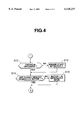
- FIG. 4 is a flow chart illustrating the remaining portion of the control routine.
- FIG. 1 A hybrid drive system incorporating the preferred implementation of the present invention is shown in FIG. 1. For simplicity in showing, the various elements are not shown in their physical relationships.
- the implementation of this invention can be used to power an automobile, truck, etc.
- First, second and third electric motors 4, 1 and 10 are electrically connected to inverters 12, 11 and 13, respectively, which are connected to a controller 16.
- the first, second and third electric motors 4, 1 and 10 are three phase AC motors, however, it should be appreciated that other types of electric motors may be used, for example multi-pole DC permanent magnet motors. In the latter case, DC/DC converters are used instead of inverters.
- the inverters 12, 11 and 13 are electrically connected by DC link 14 to a main battery pack 15 for charging the battery pack during generator mode and powering the motors 4, 1 and 10 during motor mode.
- the inverters 12, 11 and 13 are electrically interconnected by DC link 14 for allowing direct supply of current generated by one motor in generator mode to power another motor in motor mode bypassing the battery pack 15.
- the battery 15 is a lithium ion battery, however, it will be noted that other types of battery may be used, for example nickel hydrogen battery or copper battery.
- the first motor 4 has a rotor 4a in driving relationship with at least one driven wheel 8 of a vehicle.
- the first motor 4 is coupled via a continuously variable transmission (CVT) 5 to the vehicle drive transmission that includes a reduction gear 6 and a differential 7.
- the CVT 5 can change ratio continuously.
- the CVT 5 includes an input pulley, an output pulley, an input shaft, an output shaft, a V-belt, and a hydraulic control unit 9.
- the input pulley is mounted to the input shaft and the output pulley is mounted to the output shaft.
- the V-belt interconnects the input and output pulleys.
- the rotor 4a of the first motor 4 is drivingly connected to the input shaft of the CVT 5.
- the output shaft of the CVT 5 is drivingly connected to the reduction gear 6.
- the third motor 10 is used to drive an oil pump within the hydraulic control unit 9.
- a fuel powered heat engine 2 has a drive shaft 2a.
- the second motor 1 has a second rotor la in driving connection to the engine drive shaft 2a.
- a chain or belt provides the driving connection between the second rotor la of the second motor 1 and the engine drive shaft 2a.
- the engine drive shaft 2a is connected to a clutch 3 to engage and disengage the engine 2 to and from the driven wheel 8.
- the clutch 3 is positioned between the engine drive shaft 2a and the first rotor 4a of the first motor 4.
- the clutch 3 is an electromagnetic powder clutch. Torque transmitted by the electromagnetic powder clutch 3 is proportional to flow of current to energize the clutch 3.
- the controller 16 includes a microcomputer with peripheral equipment and various kinds of actuators.
- the controller 16 can perform speed control and torque control of the engine 2, control of torque transmission by the clutch 3, speed control and torque control of the first, second and third motors 4, 1 and 10, and ratio control of the CVT 5.
- the controller 16 is connected to a key switch 20.
- the key switch 20 is closed or turned on when the vehicle key is place to "ON" position or "START" position.
- the controller 16 inputs information of the battery temperature Tb, battery voltage Vb and battery current Ib.
- a battery voltage temperature sensor 21 senses temperature Tb [° C.] of the battery 15 and feeds its sensor output to the controller 16.
- a battery voltage sensor 22 senses voltage Vb [V] at terminals of the battery 15 and feeds its sensor output to the controller 16.
- a battery current sensor 23 senses the flow of electric current Ib [A] during charge and discharge to and from the battery 15 and feeds its sensor output to the controller 16.
- the controller 16 may input information of internal resistance Rb within the battery 15 instead of the battery temperature Tb.
- the internal resistance Rb is the resistance to the flow of electric current within the battery 15 and may be determined by interpolation based on measures of voltage Vb and the floe of electric current Ib.
- SOC state of charge
- An external sensor may sense the SOC.
- the SOC may be determined based on the battery voltage Vb and the battery temperature Tb as discussed in co-pending U.S. patent application Ser. No. 09/061,061, entitled “HYBRID ELECTRIC VEHICLE WITH BATTERY MANAGEMENT", filed Apr. 16, 1998 and commonly assigned herewith.
- This co-pending U.S. patent application Ser. No. 09/061,061 is hereby incorporated by reference in its entirety.
- a box 24 indicates detection of SOC for illustration purpose only.
- the controller 16 inputs information of the engine speed Ne [rpm] and the engine coolant temperature Te.
- the controller 16 uses the engine speed Ne and the coolant temperature Te to determine whether or not the engine 2 is being powered by fuel. In other words, these parameters are used to determine whether or not cranking operation of the engine 2 by the motor 1 would interfere with current operation the hybrid drive system.
- An engine speed sensor 25 senses a parameter indicative of speed of rotation of the engine drive shaft 2a and sends its output signal to the controller 16.
- An engine coolant temperature sensor 26 senses temperature of the engine oil and sends its output to the controller 16.
- the controller 16 To monitor an oil pump of the hydraulic control unit 9 for the CVT 5, the controller 16 input information of transmission oil temperature Tc and speed of rotation Nc of the motor 10. These parameters are used to determine whether or not high-speed rotation of oil pump by the motor 10 would interfere with current operation of the hydraulic control unit 9.
- an auxiliary battery 33 is provided to power the controller 16.
- FIGS. 3 and 4 illustrates the preferred implementation according to the present invention.
- step S1 the controller 16 determines whether or not the temperature Tb indicates that the main battery 15 is in the optimum state for use in powering the motors 1, 4 and 10 to keep the vehicle in operation.
- the battery temperature Tb has a great influence on charge and discharge performance of the battery 15. If the temperature Tb is lower than the lower limit of a predetermined optimum range, the charge and discharge performance drops, making it difficult for the battery 15 to meet the performance request as a source of energy of the vehicle. If the temperature Tb is higher than the upper limit of the predetermined optimum range, the performance deteriorates at a quick rate, shortening its operating life.
- the battery temperature Tb may be estimated from internal resistance Rb of the battery 15. There exists a predetermined relationship between them.
- the internal resistance Rb becomes large as the temperature Tb drops.
- the internal resistance Rb becomes small as the temperature Tb rises.
- the internal resistance Rb at a battery temperature is defined as a gradient of a V-I characteristic of the battery 15 at the temperature.
- V-I characteristic may be given by plotting measures of battery voltage Vb against measures of battery current Ib.
- step S1 it is intended to keep the battery 15 ready for charge and discharge at sufficiently high rate.
- the temperature Tb is less than or equal to a predetermined value Tb1 (Tb ⁇ Tb1) or the internal resistance Rb is greater than or equal to a predetermined value Rb1 (Rb ⁇ Rb1)
- the battery 15 will be forced to operate in charge or discharge mode. Operating the battery 15 in charge or discharge mode will increase the temperature Tb.
- step S determines that the battery 15 is not in the optimum state for use in powering the motors 1, 4 and 10 to keep the vehicle in operation. In this case, the routine goes from step S1 to step S3. If the interrogation in step S1 results in negative, the controller 16 determines that battery 15 is in the optimum state for use in powering the motors 1, 4 and 10 to keep the vehicle in operation. Then, the routine goes to step 52 for allowing normal charge and discharge operation of the battery 15.
- step S3 the controller 16 inputs state of charge (SOC) of the battery 15 and determines whether or not the SOC is greater than or equal to a predetermined value SOC1. If this is the case, the routine goes to step S4. If this is not the case, SOC ⁇ SOC1, the routine goes to step S12 as shown in FIG. 12. In step S4, the controller 16 determines whether or not engine coolant temperature Te is less than or equal to a predetermined value Te1 If this is the case, the routine goes to step S5. If this is not the case, Te>Te1, the routine goes to step S9.
- SOC state of charge
- step S5 the controller 16 determines whether or not the engine 2 is being powered by fuel. If this is not the case, the routine goes to step S6.
- step S6 the controller 16 conducts supply of current from the battery 15 to the motor 1, causing the motor 1 to start the engine 2.
- step S7 the controller 16 determines whether or not there is any power request demand on the motor 1 for the purpose of driving the vehicle. If there is no such power request command, the routine goes to step S8.
- step S8 the controller 16 conducts supply of current from the battery 15 to the motor 1.
- the motor 1 operates in power mode to assist the engine 2 in turning the drive shaft 2a.
- Such forced discharge from the battery 15 causes an increase in temperature Tb. Subsequently, if the temperature Tb exceeds Tb1 or the internal resistance Rb drops below Rb1, the controller 16 determines that the battery 15 has recovered and terminates the forced discharge from the battery 15.
- the routine goes from step S7 or S8 to step S9.
- step S9 the controller 16 determines whether or not the transmission oil temperature Tc is less than or equal to a predetermined value Tc1. If this is the case, the routine goes to step S10.
- step S10 the controller 16 determines whether or not motor speed Nc of the motor 10 for driving the oil pump is less than or equal to a predetermined value Nc1. If this is the case, the routine goes to step S11.
- step S11 the controller 16 conducts supply of current to the motor 10, causing the motor 10 to rotate at high speed. In this manner, the controller 16 conducts forced discharge from the battery 15 to both of the motors 1 and 10 to quickly increase the battery temperature Tb, thus shortening time required to recover the battery 15.
- step S12 of FIG. 4 the controller 16 determines whether or not the engine 2 is in operation or not. If this is not the case, the routine proceeds to S13. In step S13, the controller 16 conducts supply of current from the battery 15 to the motor 1, causing the motor 1 to start the engine 2. After step 513 or step S12, the routine goes to step S14. In step S14, the controller 16 determines whether or not there is any power request demand on the motor 1 for the purpose of driving the vehicle. If this is not the case, the routine goes to step S15. In step S15, the controller 16 operates the motor 1 in generator mode, charging the battery 15. After step S15, the routine goes to step S1 in FIG. 3. If, in step S14, there is power request demand on the motor 1 for the purpose of driving the vehicle, the routine goes from step S14 to step S1.
- the forced charge to the battery 15 causes an increase in the battery temperature Tb. Subsequently, if the temperature Tb exceeds Tb1 or the internal resistance Rb drops below Rb1, the controller 16 determines that the battery 15 has recovered and terminates the forced charge to the battery 15.
- the present invention is described as being operational with the vehicle hybrid drive system as shown in FIGS. 1 and 2.
- the hybrid drive system is not limited to this example.
- the present invention is operational with any type of vehicle hybrid drive systems as long as an engine and/or an electric motor are in driving relationship with driven wheel of a vehicle. In the example illustrated in FIG. 1, two electric motors 1 and 4 share engine start-up, generation and vehicle driving operations.
- the present invention is operational with a vehicle hybrid drive system where a single electric motor performs all of the operations.
Abstract
A battery management for a hybrid drive system for a vehicle recovers input and output performance of a battery if the battery temperature is low. If the battery temperature is less than or equal to a predetermined value (or if the battery internal resistance is greater than or equal to a predetermined value), the battery needs to recover its input and output performance. Under this condition, the state of charge (SOC) of the battery is determined and compared with a predetermined value. The comparison result is used to determine whether the battery is capable of discharging or the battery needs charging. If SOC is greater than or equal to the predetermined value, a controller conducts forced discharge from the battery to operate an electric motor of the hybrid drive system in power mode. This forced discharge causes an increase ion the battery temperature, thus causing the battery to recover its input and output performance.
Description
The present invention relates to a hybrid drive system for a vehicle, and more particularly to a battery management in arctic environments.
A hybrid drive system for a vehicle comprises a fuel powered heat engine and a battery powered electric motor, at least one of which is used to drive the vehicle. In the hybrid drive system, a battery provides electric power to the motor. The output of the battery must be maintained at sufficiently high level under varying environment conditions to meet power request demand on the motor. If the battery temperature drops, the internal resistance within the battery increases. This causes a drop in the level of the output of the battery. Accordingly, there exists a need to maintain the output of the battery at a sufficiently high level under varying temperature conditions.
An object of the present invention is to provide a battery management, which recovers the level of input and output to and from a battery of a hybrid drive system if the battery temperature tends to drop.
According to one aspect of the present invention, there is provided a hybrid drive system for a vehicle, comprising:
a battery;
a battery powered electric motor by said battery;
sensors to sense parameters indicative of the state of said battery; and
a controller to input information of state of charge (SOC) of said battery from said sensed parameters indicative of the state of said battery,
said controller being operative to establish, in response to a demand for recovery of said battery, supply of electric energy from said battery to said electric motor when the state of charge (SOC) of said battery is greater than or equal to a predetermined value.
According to a specific aspect of the present invention, there is provided a hybrid drive system for a vehicle, comprising:
a battery;
a battery powered electric motor by said battery;
sensors to sense parameters indicative of the state of said battery; and
a controller to input information of battery temperature of said battery and information of state of charge (SOC) of said battery from said sensed parameters indicative of the state of said battery,
said controller being operative to conduct a forced discharge from said battery by establishing supply of electric energy from said battery to said electric motor when the battery temperature is less than or equal to a predetermined temperature value and the state of charge (SOC) of said battery is greater than or equal to a predetermined SOC value,
said controller being operative to conduct a forced charge to said battery by establishing supply of electric energy to said battery from said electric motor when the battery temperature is less than or equal to said predetermined temperature value and the state of charge (SOC) of said battery is less than said predetermined SOC value.
According to a further aspect of the present invention, there is provided a hybrid drive system for a vehicle, comprising:
a fuel powered engine;
a battery;
a battery powered electric motor by said battery, said electric motor being in driving relationship with said engine;
sensors to sense parameters indicative of the state of said battery;
sensors to sense parameters indicative of the state of said engine;
a controller to input information of state of charge (SOC) of said battery from said sensed parameters indicative of the state of said battery,
said controller being operative to determine based on said sensed parameters indicative of said engine whether or not said engine is being powered by fuel,
said controller being operative to conduct a forced discharge from said battery, in response to a demand for recovery of said battery, by establishing supply of electric energy from said battery to said electric motor when the state of charge (SOC) of said battery is greater than or equal to a predetermined value, thereby to cause said electric motor to start up said engine unless said engine is being powered by fuel and to operate in power mode after starting up said engine.
According to another aspect of the present invention, there is provided a method for the management of a battery to power an electric motor of a hybrid drive system for a vehicle, comprising:
sensing parameters indicative of the state of the battery;
deriving information of the state of charge (SOC) of the battery from said sensed parameters indicative of the state of the battery; and
establishing, in response to a demand for recovery of the battery, supply of electric energy from the battery to the electric motor when the state of charge (SOC) of the battery is greater than or equal to a predetermined value.
FIG. 1 is a generalized block diagram of a hybrid drive system for a vehicle.
FIG. 2 illustrates major components positioned in the vehicle.
FIG. 3 is a flow chart illustrating a portion of a control routine.
FIG. 4 is a flow chart illustrating the remaining portion of the control routine.
A hybrid drive system incorporating the preferred implementation of the present invention is shown in FIG. 1. For simplicity in showing, the various elements are not shown in their physical relationships. The implementation of this invention can be used to power an automobile, truck, etc.
First, second and third electric motors 4, 1 and 10 are electrically connected to inverters 12, 11 and 13, respectively, which are connected to a controller 16. In the preferred embodiment, the first, second and third electric motors 4, 1 and 10 are three phase AC motors, however, it should be appreciated that other types of electric motors may be used, for example multi-pole DC permanent magnet motors. In the latter case, DC/DC converters are used instead of inverters. The inverters 12, 11 and 13 are electrically connected by DC link 14 to a main battery pack 15 for charging the battery pack during generator mode and powering the motors 4, 1 and 10 during motor mode. The inverters 12, 11 and 13 are electrically interconnected by DC link 14 for allowing direct supply of current generated by one motor in generator mode to power another motor in motor mode bypassing the battery pack 15. In the preferred embodiment, the battery 15 is a lithium ion battery, however, it will be noted that other types of battery may be used, for example nickel hydrogen battery or copper battery.
The first motor 4 has a rotor 4a in driving relationship with at least one driven wheel 8 of a vehicle. In particular, the first motor 4 is coupled via a continuously variable transmission (CVT) 5 to the vehicle drive transmission that includes a reduction gear 6 and a differential 7. The CVT 5 can change ratio continuously. In the preferred embodiment, the CVT 5 includes an input pulley, an output pulley, an input shaft, an output shaft, a V-belt, and a hydraulic control unit 9. The input pulley is mounted to the input shaft and the output pulley is mounted to the output shaft. The V-belt interconnects the input and output pulleys. The rotor 4a of the first motor 4 is drivingly connected to the input shaft of the CVT 5. The output shaft of the CVT 5 is drivingly connected to the reduction gear 6. It should be appreciated that other type of CVT may be used, for example hydrostatic and friction CVTs. The third motor 10 is used to drive an oil pump within the hydraulic control unit 9.
A fuel powered heat engine 2 has a drive shaft 2a. The second motor 1 has a second rotor la in driving connection to the engine drive shaft 2a. In the preferred embodiment, a chain or belt provides the driving connection between the second rotor la of the second motor 1 and the engine drive shaft 2a. The engine drive shaft 2a is connected to a clutch 3 to engage and disengage the engine 2 to and from the driven wheel 8. The clutch 3 is positioned between the engine drive shaft 2a and the first rotor 4a of the first motor 4. The clutch 3 is an electromagnetic powder clutch. Torque transmitted by the electromagnetic powder clutch 3 is proportional to flow of current to energize the clutch 3.
The controller 16 includes a microcomputer with peripheral equipment and various kinds of actuators. The controller 16 can perform speed control and torque control of the engine 2, control of torque transmission by the clutch 3, speed control and torque control of the first, second and third motors 4, 1 and 10, and ratio control of the CVT 5.
Referring to FIG. 2, the controller 16 is connected to a key switch 20. The key switch 20 is closed or turned on when the vehicle key is place to "ON" position or "START" position.
To monitor the main battery pack 15, the controller 16 inputs information of the battery temperature Tb, battery voltage Vb and battery current Ib. In this example, a battery voltage temperature sensor 21 senses temperature Tb [° C.] of the battery 15 and feeds its sensor output to the controller 16. A battery voltage sensor 22 senses voltage Vb [V] at terminals of the battery 15 and feeds its sensor output to the controller 16. A battery current sensor 23 senses the flow of electric current Ib [A] during charge and discharge to and from the battery 15 and feeds its sensor output to the controller 16. The controller 16 may input information of internal resistance Rb within the battery 15 instead of the battery temperature Tb. As is well known, the internal resistance Rb is the resistance to the flow of electric current within the battery 15 and may be determined by interpolation based on measures of voltage Vb and the floe of electric current Ib. As an important parameter indicative of the state of the battery 15, the state of charge (SOC) [%] of the battery 15 is well known. An external sensor may sense the SOC. Alternatively, the SOC may be determined based on the battery voltage Vb and the battery temperature Tb as discussed in co-pending U.S. patent application Ser. No. 09/061,061, entitled "HYBRID ELECTRIC VEHICLE WITH BATTERY MANAGEMENT", filed Apr. 16, 1998 and commonly assigned herewith. This co-pending U.S. patent application Ser. No. 09/061,061 is hereby incorporated by reference in its entirety. In FIG. 2, a box 24 indicates detection of SOC for illustration purpose only.
To monitor the engine 2, the controller 16 inputs information of the engine speed Ne [rpm] and the engine coolant temperature Te. The controller 16 uses the engine speed Ne and the coolant temperature Te to determine whether or not the engine 2 is being powered by fuel. In other words, these parameters are used to determine whether or not cranking operation of the engine 2 by the motor 1 would interfere with current operation the hybrid drive system. An engine speed sensor 25 senses a parameter indicative of speed of rotation of the engine drive shaft 2a and sends its output signal to the controller 16. An engine coolant temperature sensor 26 senses temperature of the engine oil and sends its output to the controller 16.
To monitor an oil pump of the hydraulic control unit 9 for the CVT 5, the controller 16 input information of transmission oil temperature Tc and speed of rotation Nc of the motor 10. These parameters are used to determine whether or not high-speed rotation of oil pump by the motor 10 would interfere with current operation of the hydraulic control unit 9.
Also illustrated in FIG. 2 are actuators to adjust fuel injection 30, ignition timing 31 and valve timing 32 of the engine 2. To power the controller 16, an auxiliary battery 33 is provided.
The flow chart of FIGS. 3 and 4 illustrates the preferred implementation according to the present invention.
The controller 16 repeats execution of this control routine while the key switch 20 is being turned on. In step S1, the controller 16 determines whether or not the temperature Tb indicates that the main battery 15 is in the optimum state for use in powering the motors 1, 4 and 10 to keep the vehicle in operation.
Describing on the relationship between the state of the battery 15 and its temperature Tb, the battery temperature Tb has a great influence on charge and discharge performance of the battery 15. If the temperature Tb is lower than the lower limit of a predetermined optimum range, the charge and discharge performance drops, making it difficult for the battery 15 to meet the performance request as a source of energy of the vehicle. If the temperature Tb is higher than the upper limit of the predetermined optimum range, the performance deteriorates at a quick rate, shortening its operating life.
The battery temperature Tb may be estimated from internal resistance Rb of the battery 15. There exists a predetermined relationship between them. The internal resistance Rb becomes large as the temperature Tb drops. The internal resistance Rb becomes small as the temperature Tb rises.
The internal resistance Rb at a battery temperature is defined as a gradient of a V-I characteristic of the battery 15 at the temperature. Such V-I characteristic may be given by plotting measures of battery voltage Vb against measures of battery current Ib.
In the preferred implementation of the present invention, it is intended to keep the battery 15 ready for charge and discharge at sufficiently high rate. Thus, if, in step S1, the temperature Tb is less than or equal to a predetermined value Tb1 (Tb≦Tb1) or the internal resistance Rb is greater than or equal to a predetermined value Rb1 (Rb≧Rb1), the battery 15 will be forced to operate in charge or discharge mode. Operating the battery 15 in charge or discharge mode will increase the temperature Tb.
If the interrogation in step S results in affirmative, the controller 16 determines that the battery 15 is not in the optimum state for use in powering the motors 1, 4 and 10 to keep the vehicle in operation. In this case, the routine goes from step S1 to step S3. If the interrogation in step S1 results in negative, the controller 16 determines that battery 15 is in the optimum state for use in powering the motors 1, 4 and 10 to keep the vehicle in operation. Then, the routine goes to step 52 for allowing normal charge and discharge operation of the battery 15.
In step S3, the controller 16 inputs state of charge (SOC) of the battery 15 and determines whether or not the SOC is greater than or equal to a predetermined value SOC1. If this is the case, the routine goes to step S4. If this is not the case, SOC<SOC1, the routine goes to step S12 as shown in FIG. 12. In step S4, the controller 16 determines whether or not engine coolant temperature Te is less than or equal to a predetermined value Te1 If this is the case, the routine goes to step S5. If this is not the case, Te>Te1, the routine goes to step S9.
In the case where SOC is greater than or equal to SOC1 and Te is less than or equal to Te1, the controller 16 conducts forced discharge from the battery 15 to cause an increase in battery temperature Tb. In step S5, the controller 16 determines whether or not the engine 2 is being powered by fuel. If this is not the case, the routine goes to step S6. In step S6, the controller 16 conducts supply of current from the battery 15 to the motor 1, causing the motor 1 to start the engine 2. The routine goes to step S7 after the engine 2 has been started. In step S7, the controller 16 determines whether or not there is any power request demand on the motor 1 for the purpose of driving the vehicle. If there is no such power request command, the routine goes to step S8. In step S8, the controller 16 conducts supply of current from the battery 15 to the motor 1. The motor 1 operates in power mode to assist the engine 2 in turning the drive shaft 2a.
Such forced discharge from the battery 15 causes an increase in temperature Tb. Subsequently, if the temperature Tb exceeds Tb1 or the internal resistance Rb drops below Rb1, the controller 16 determines that the battery 15 has recovered and terminates the forced discharge from the battery 15.
In the preferred implementation, the routine goes from step S7 or S8 to step S9. In step S9, the controller 16 determines whether or not the transmission oil temperature Tc is less than or equal to a predetermined value Tc1. If this is the case, the routine goes to step S10. In step S10, the controller 16 determines whether or not motor speed Nc of the motor 10 for driving the oil pump is less than or equal to a predetermined value Nc1. If this is the case, the routine goes to step S11. In step S11, the controller 16 conducts supply of current to the motor 10, causing the motor 10 to rotate at high speed. In this manner, the controller 16 conducts forced discharge from the battery 15 to both of the motors 1 and 10 to quickly increase the battery temperature Tb, thus shortening time required to recover the battery 15.
If SOC of the battery 15 is less than SOC1, the controller 16 conducts forced charge to the battery 15. In step S12 of FIG. 4, the controller 16 determines whether or not the engine 2 is in operation or not. If this is not the case, the routine proceeds to S13. In step S13, the controller 16 conducts supply of current from the battery 15 to the motor 1, causing the motor 1 to start the engine 2. After step 513 or step S12, the routine goes to step S14. In step S14, the controller 16 determines whether or not there is any power request demand on the motor 1 for the purpose of driving the vehicle. If this is not the case, the routine goes to step S15. In step S15, the controller 16 operates the motor 1 in generator mode, charging the battery 15. After step S15, the routine goes to step S1 in FIG. 3. If, in step S14, there is power request demand on the motor 1 for the purpose of driving the vehicle, the routine goes from step S14 to step S1.
The forced charge to the battery 15 causes an increase in the battery temperature Tb. Subsequently, if the temperature Tb exceeds Tb1 or the internal resistance Rb drops below Rb1, the controller 16 determines that the battery 15 has recovered and terminates the forced charge to the battery 15.
In the preferred implementation, the present invention is described as being operational with the vehicle hybrid drive system as shown in FIGS. 1 and 2. The hybrid drive system is not limited to this example. The present invention is operational with any type of vehicle hybrid drive systems as long as an engine and/or an electric motor are in driving relationship with driven wheel of a vehicle. In the example illustrated in FIG. 1, two electric motors 1 and 4 share engine start-up, generation and vehicle driving operations. The present invention is operational with a vehicle hybrid drive system where a single electric motor performs all of the operations.
The content of disclosure of Japanese Patent Application No. 10-189397 (filed Jul. 3, 1998) is hereby incorporated by reference in its entirety.
The above-described implementation of the present invention is an example implementation. Moreover various modifications to the present invention may occur to those skilled in the art and will fall within the scope of the present invention as set forth below.
Claims (8)
1. A hybrid drive system for a vehicle, comprising;
a battery;
an electric motor powered by said battery;
sensors to sense parameters indicative of a state of said battery; and
a controller to input information of battery temperature of said battery and information of a state of charge (SOC) of said battery from said sensed parameters indicative of the state of said battery,
said controller being operative to conduct a forced discharge from said battery by establishing supply of electric energy from said battery to said electric motor when the battery temperature is less than or equal to a predetermined temperature value and the state of charge (SOC) of said battery is greater than or equal to a predetermined SOC value,
said controller being operative to conduct a forced charge to said battery from said electric motor by establishing supply of electric energy to said battery from said electric motor when the battery temperature is less than or equal to said predetermined temperature value and the state of charge (SOC) of said battery is less than said predetermined SOC value.
2. A hybrid drive system for a vehicle, comprising:
a fuel powered engine;
a battery;
an electric motor powered by said battery, said electric motor being in driving relationship with said engine;
sensors to sense parameters indicative of a state of said battery;
sensors to sense parameters indicative of a state of said engine;
a controller to input information of a state of charge (SOC) of said battery from said sensed parameters indicative of the state of said battery,
said controller being operative to determine based on said sensed parameters indicative of the state of said engine whether or not said engine is being powered by fuel,
said controller being operative to conduct a forced discharge from said battery, by establishing supply of electric energy from said battery to said electric motor when the state of charge (SOC) of said battery is greater than or equal to a predetermined value, thereby to cause said electric motor to start up said engine unless said engine is being powered by fuel and to operate in power mode after starting up said engine.
3. The hybrid drive system as claimed in claim 2, further comprising:
a continuously variable transmission (CVT) having an oil pump in driving association with said engine;
an electric motor for driving said oil pump; and
a sensor to sense oil temperature of oil within said oil pump;
wherein said controller is operative to conduct said forced discharge from said battery by establishing supply of electric energy from said battery to said electric motor for driving said oil pump when the sensed oil temperature is less than or equal to a predetermined temperature value.
4. The hybrid drive system as claimed in claim 2, wherein said controller is operative to conduct said forced charge operation when the state of charge (SOC) of said battery is less than said predetermined SOC value by establishing supply of electric energy from said battery to said electric motor to start up said engine and then establishing supply of electric energy to said battery from said motor by operating said electric motor in generator mode.
5. The hybrid drive system as claimed in claim 2, wherein said sensors to sense parameters indicative of the state of said battery includes a battery temperature sensor to sense battery temperature of said battery, a battery voltage sensor to sense voltage at terminals of said battery and a battery current sensor to sense flow of electric current during discharge and charge from and to said battery.
6. The hybrid drive system as claimed in claim 2, wherein said sensors to sense parameters indicative of the state of said engine includes an engine speed sensor to sense a parameter indicative of speed of rotation of said engine and an engine coolant temperature sensor to sense temperature of the engine coolant.
7. A method for the management of an electric motor for powering an electric motor of a vehicular hybrid drive system including a fuel powered engine, comprising:
sensing parameters indicative of a state of a battery;
sensing parameters indicative of a state of the engine;
deriving information of a state of charge (SOC) of the battery from said sensed parameters indicative of the state of the battery;
determining based on said sensed parameters indicative of the state of the engine whether or not the engine is being powered by fuel; and
conducting a forced discharge from the battery, by establishing supply of electric energy from the battery to the electric motor when the state of charge (SOC) of the battery is greater than or equal to a predetermined value, thereby to cause the electric motor to start up the engine unless the engine is being powered by fuel and to operate in power mode after starting up the engine.
8. A method for the management of a battery to power an electric motor of a hybrid drive system for a vehicle, comprising:
sensing parameters indicative of the state of the battery;
deriving information of the state of charge (SOC) of the battery from said sensed parameters indicative of the state of the battery; and
deriving information of battery temperature of the battery and information of the state of charge (SOC) of the battery from said sensed parameters indicative of the state of the battery,
conducting a forced discharge from the battery by establishing supply of electric energy from the battery to the electric motor when the battery temperature is less than or equal to a predetermined temperature value and the state of charge (SOC) of the battery is greater than or equal to a predetermined SOC value,
conducting a forced charge to the battery by establishing supply of electric energy to the battery from the electric motor when the battery temperature is less than or equal to said predetermined temperature value and the state of charge (SOC) of said battery is less than said predetermined SOC value.
Applications Claiming Priority (2)
| Application Number | Priority Date | Filing Date | Title |
|---|---|---|---|
| JP18939798A JP3449226B2 (en) | 1998-07-03 | 1998-07-03 | Battery control device for hybrid vehicle |
| JP10-189397 | 1998-07-03 |
Publications (1)
| Publication Number | Publication Date |
|---|---|
| US6118237A true US6118237A (en) | 2000-09-12 |
Family
ID=16240620
Family Applications (1)
| Application Number | Title | Priority Date | Filing Date |
|---|---|---|---|
| US09/346,532 Expired - Lifetime US6118237A (en) | 1998-07-03 | 1999-07-02 | Vehicular hybrid drive system with battery arctic management |
Country Status (3)
| Country | Link |
|---|---|
| US (1) | US6118237A (en) |
| JP (1) | JP3449226B2 (en) |
| DE (1) | DE19929594A1 (en) |
Cited By (58)
| Publication number | Priority date | Publication date | Assignee | Title |
|---|---|---|---|---|
| US6301529B1 (en) * | 1999-07-21 | 2001-10-09 | Nissan Motor Co., Ltd | Driving apparatus and method for hybrid vehicle |
| WO2002025794A1 (en) * | 2000-09-20 | 2002-03-28 | Daimlerchrysler Ag | Method for regulating the generator voltage in a motor vehicle |
| US6366838B1 (en) * | 2000-01-20 | 2002-04-02 | Nissan Motor Co., Ltd. | Vehicle control device |
| EP1193108A2 (en) * | 2000-09-15 | 2002-04-03 | Transportation Techniques, LLC | Method and apparatus for adaptive energy management of a hybrid electric vehicle |
| FR2818201A1 (en) * | 2000-12-15 | 2002-06-21 | Renault | Hybrid automobile drive with battery temperature regulation, has supervisor that monitors and controls battery to recharge battery when it exceeds a predetermined high level to bring temperature down to a predetermined low level |
| US6441574B1 (en) * | 2000-10-27 | 2002-08-27 | Ford Motor Company | Energy control strategy for a hybrid electric vehicle |
| US6450275B1 (en) * | 2000-11-02 | 2002-09-17 | Ford Motor Company | Power electronics cooling for a hybrid electric vehicle |
| US20030033060A1 (en) * | 2001-08-01 | 2003-02-13 | Aisin Aw Co., Ltd. | Hybrid type vehicle drive control apparatus, hybrid type vehicle drive control method, and program thereof |
| US6533054B1 (en) * | 1999-01-29 | 2003-03-18 | Sram Deutschland Gmbh | Drive unit for an electrically operated vehicle |
| US6583592B2 (en) * | 2000-08-04 | 2003-06-24 | Suzuki Motor Corporation | Control apparatus for hybrid vehicle |
| US20030169001A1 (en) * | 2001-09-10 | 2003-09-11 | Hiroshi Murakami | Vehicle driving apparatus |
| US20030231005A1 (en) * | 2002-03-18 | 2003-12-18 | Hirofumi Kohama | Battery control apparatus |
| US6750632B2 (en) | 2002-06-04 | 2004-06-15 | Caterpillar Inc | Starting system for an internal combustion system and method of operating same |
| US20040227348A1 (en) * | 2003-05-16 | 2004-11-18 | Honda Motor Co., Ltd. | Hybrid type driving apparatus |
| US20040249525A1 (en) * | 2003-06-05 | 2004-12-09 | Aisin Aw Co., Ltd. | Hybrid type vehicle driving controller, hybrid type vehicle driving control method and its program |
| US20050196662A1 (en) * | 2003-09-19 | 2005-09-08 | Ford Global Technologies, Llc | Method for heating a battery in a hybrid electric vehicle |
| EP1903670A1 (en) * | 2005-07-12 | 2008-03-26 | Toyota Jidosha Kabushiki Kaisha | Secondary battery control device and control method |
| US20080142282A1 (en) * | 2006-12-19 | 2008-06-19 | Bradley Wayne Bartilson | Short-Cycling Serial Hybrid Drivetrain with High Power Density Storage |
| US20080223632A1 (en) * | 2006-12-19 | 2008-09-18 | Bradley Wayne Bartilson | Hybrid drivetrain with waste heat energy conversion into electricity |
| US20080223637A1 (en) * | 2006-12-19 | 2008-09-18 | Bradley Wayne Bartilson | Safe, Super-efficient, Four-wheeled Vehicle Employing Large Diameter Wheels with Continuous-Radius Tires, with Leaning Option |
| CN100422895C (en) * | 2006-02-16 | 2008-10-01 | 北京航空航天大学 | BCM controller assembly for light mixed power automobile |
| US7468562B1 (en) * | 2006-12-25 | 2008-12-23 | Mato Barbic | Intermittant electrical charging AC/DC driving system |
| CN100452530C (en) * | 2005-05-16 | 2009-01-14 | 比亚迪股份有限公司 | Temperature control system and method for power battery pack of electric vehicle |
| US7541756B1 (en) * | 2005-01-25 | 2009-06-02 | Cooper Technologies Company | Temperature compensated test for a power distribution switching device |
| US20090184692A1 (en) * | 2008-01-22 | 2009-07-23 | Honda Motors Co., Ltd. | Acg output voltage control |
| US20090184693A1 (en) * | 2008-01-22 | 2009-07-23 | Richard Owens | Acg output voltage control |
| CN101616829A (en) * | 2007-02-21 | 2009-12-30 | 丰田自动车株式会社 | Vehicle and control method thereof |
| ITMO20080266A1 (en) * | 2008-10-15 | 2010-04-16 | Galileo S R L | ELECTROGEN DEVICE FOR AN ELECTRIC WHEELCHAIR. |
| US20100156333A1 (en) * | 2008-12-24 | 2010-06-24 | Aisin Aw Co., Ltd. | Motor control device and drive device for hybrid vehicle |
| US20100181125A1 (en) * | 2006-12-25 | 2010-07-22 | Byd Co., Ltd. | Hybrid power output system |
| US20100250039A1 (en) * | 2009-03-24 | 2010-09-30 | Ford Global Technologies, Llc | Method And System For Initiating Starting Of An Engine In A Hybrid Electric Vehicle |
| US20110120788A1 (en) * | 2006-12-25 | 2011-05-26 | Byd Company Limited | Hybrid power output system |
| US20110129323A1 (en) * | 2005-03-18 | 2011-06-02 | Matthias Ehrat | Device for Moving and Positioning an Object in Space |
| WO2012076928A1 (en) | 2010-12-09 | 2012-06-14 | Renault Trucks | Method for controlling a hybrid automotive vehicle and hybrid vehicle adapted to such a method |
| US20120158228A1 (en) * | 2010-12-21 | 2012-06-21 | GM Global Technology Operations LLC | Method and System for Conditioning an Energy Storage System (ESS) for a Vehicle |
| US20120255384A1 (en) * | 2011-04-11 | 2012-10-11 | Zf Friedrichshafen Ag | Device with a transmission to support at least one auxiliary device of a vehicle with drive energy |
| US20120323427A1 (en) * | 2010-03-30 | 2012-12-20 | Toyota Jidosha Kabushiki Kaisha | Vehicle control apparatus and vehicle control method |
| CN103228517A (en) * | 2010-11-30 | 2013-07-31 | 戴姆勒股份公司 | Equipment warm-up battery for hybrid electric automobile |
| US20130211642A1 (en) * | 2010-05-29 | 2013-08-15 | Audi Ag | Method for operating an electric battery of a motor vehicle, and motor vehicle verfahren zum betreiben einer elektrischen batterie eines kraftfahrzeugs sowie kraftfahrzeug |
| US8808136B2 (en) | 2009-05-07 | 2014-08-19 | Volvo Construction Equipment Ab | Working machine and a method for operating a working machine |
| US8823325B2 (en) | 2010-11-25 | 2014-09-02 | Industrial Technology Research Institute | Method for checking and modulating battery capacity and power based on discharging/charging characteristics |
| US9008858B1 (en) | 2014-03-31 | 2015-04-14 | Toyota Motor Engineering & Manufacturing North America, Inc. | System and method for providing adaptive vehicle settings based on a known route |
| US20150166041A1 (en) * | 2013-12-13 | 2015-06-18 | Toyota Jidosha Kabushiki Kaisha | Hybrid vehicle |
| CN105102252A (en) * | 2013-05-31 | 2015-11-25 | 爱信艾达株式会社 | Vehicle drive device |
| CN105182264A (en) * | 2014-06-05 | 2015-12-23 | 西门子公司 | Generating A Parameter Map In Magnetic Resonance Technology |
| US9266443B2 (en) | 2014-03-31 | 2016-02-23 | Toyota Motor Engineering & Manufacturing North America, Inc. | System and method for adaptive battery charge and discharge rates and limits on known routes |
| US9290108B2 (en) | 2014-03-31 | 2016-03-22 | Toyota Motor Engineering & Manufacturing North America, Inc. | System and method for adaptive battery temperature control of a vehicle over a known route |
| US9446657B2 (en) | 2013-05-31 | 2016-09-20 | Aisin Aw Co., Ltd. | Vehicle driving device |
| US9539890B2 (en) | 2013-05-31 | 2017-01-10 | Aisin Aw Co., Ltd. | Vehicle drive device |
| US9695760B2 (en) | 2014-03-31 | 2017-07-04 | Toyota Motor Engineering & Manufacturing North America, Inc. | System and method for improving energy efficiency of a vehicle based on known route segments |
| US20170366112A1 (en) | 2012-12-03 | 2017-12-21 | General Electric Company | Electric Drive System and Energy Management Method |
| CN108116241A (en) * | 2016-11-28 | 2018-06-05 | 上海汽车集团股份有限公司 | Adjusting method, device and the automobile of hybrid electric vehicle electric quantity equalization point |
| US10008904B2 (en) | 2013-05-31 | 2018-06-26 | Aisin Aw Co., Ltd. | Vehicle drive device |
| CN109596986A (en) * | 2018-12-29 | 2019-04-09 | 蜂巢能源科技有限公司 | Power battery pack internal resistance estimation on line method and battery management system |
| CN110015200A (en) * | 2017-07-19 | 2019-07-16 | 现代自动车株式会社 | Vehicle and its method with the controller for managing battery |
| US10367345B2 (en) | 2016-04-06 | 2019-07-30 | Toyota Jidosha Kabushiki Kaisha | Temperature detection device |
| US11208105B2 (en) | 2016-07-12 | 2021-12-28 | Denso Corporation | Vehicle control device |
| US11661165B1 (en) * | 2017-01-11 | 2023-05-30 | Brunswick Corporation | PCM controlled charging system |
Families Citing this family (17)
| Publication number | Priority date | Publication date | Assignee | Title |
|---|---|---|---|---|
| JP3926514B2 (en) * | 1999-08-17 | 2007-06-06 | 本田技研工業株式会社 | Control device for hybrid vehicle |
| JP4106864B2 (en) * | 2000-12-04 | 2008-06-25 | トヨタ自動車株式会社 | Vehicle control device |
| DE10312591B4 (en) * | 2003-03-21 | 2014-07-31 | Volkswagen Ag | Charging procedure for a rechargeable battery |
| DE10318882A1 (en) * | 2003-04-17 | 2004-11-04 | Volkswagen Ag | Device and method for energy management in a motor vehicle |
| JP4807058B2 (en) | 2005-11-10 | 2011-11-02 | パナソニック株式会社 | Vehicle power supply |
| JP4706493B2 (en) * | 2006-02-08 | 2011-06-22 | トヨタ自動車株式会社 | Control device for secondary battery mounted on vehicle |
| DE102006006327B4 (en) | 2006-02-11 | 2018-03-22 | FEV Europe GmbH | hybrid drive |
| JP2008042980A (en) * | 2006-08-02 | 2008-02-21 | Hitachi Ltd | Drive controller of rail vehicle |
| JP4172524B1 (en) * | 2007-04-24 | 2008-10-29 | トヨタ自動車株式会社 | Vehicle and control method thereof |
| DE102008040916A1 (en) * | 2008-08-01 | 2010-02-04 | Zf Friedrichshafen Ag | Electrical energy storage heating method for vehicle, involves charging electrical energy storage until predetermined minimum temperature of energy storage is obtained, and determining calculated current collective |
| JP5482280B2 (en) * | 2010-02-18 | 2014-05-07 | ソニー株式会社 | Information processing apparatus, electric vehicle, and discharge management method |
| DE102011015539A1 (en) * | 2011-03-30 | 2012-10-04 | GM Global Technology Operations LLC (n. d. Gesetzen des Staates Delaware) | Method for operating powertrain of motor home that is utilized in camping site, involves switching-on operation mode, where engine is switched-on, and battery is charged in operation mode if charging state lies above threshold value |
| DE102011113079A1 (en) * | 2011-09-09 | 2013-03-14 | Volkswagen Aktiengesellschaft | Method for operating vehicle, particularly hybrid vehicle by control device, involves operating electric machine in secondary operating mode with kinetic energy, and storing electric energy generated from electric machine |
| DE102013202999A1 (en) * | 2013-02-25 | 2014-08-28 | Zf Friedrichshafen Ag | Method for heating traction battery in propulsion system of city bus on given operating temperature, involves delivering mechanical power by energy receiving unit of vehicle, and driving electric machine by combustion engine in load mode |
| JP6070444B2 (en) * | 2013-06-28 | 2017-02-01 | アイシン・エィ・ダブリュ株式会社 | Vehicle drive device |
| JP6545435B2 (en) * | 2014-03-07 | 2019-07-17 | 三菱重工業株式会社 | Vehicle control device, vehicle, and control method of vehicle |
| JP7426332B2 (en) | 2020-11-20 | 2024-02-01 | プライムプラネットエナジー&ソリューションズ株式会社 | Charging control device |
Citations (7)
| Publication number | Priority date | Publication date | Assignee | Title |
|---|---|---|---|---|
| US4407132A (en) * | 1980-02-20 | 1983-10-04 | Daihatsu Motor Co., Ltd. | Control apparatus and method for engine/electric hybrid vehicle |
| US4709202A (en) * | 1982-06-07 | 1987-11-24 | Norand Corporation | Battery powered system |
| US5363031A (en) * | 1989-12-05 | 1994-11-08 | Norand Corporation | Fast battery charger |
| US5823280A (en) * | 1995-01-12 | 1998-10-20 | Nevcor, Inc. | Hybrid parallel electric vehicle |
| US5873426A (en) * | 1996-04-04 | 1999-02-23 | Toyota Jidosha Kabushiki Kaisha | Hybrid vehicle drive system having means for using at least engine as drive power source in special vehicle operating state, to assure sufficient drive force |
| US5939861A (en) * | 1996-05-24 | 1999-08-17 | Hino Jidosha Kogyo Kabushiki Kaisha | Control system for on-vehicle battery |
| US6007443A (en) * | 1996-02-16 | 1999-12-28 | Nippon Soken, Inc. | Hybrid vehicle |
-
1998
- 1998-07-03 JP JP18939798A patent/JP3449226B2/en not_active Expired - Fee Related
-
1999
- 1999-06-28 DE DE19929594A patent/DE19929594A1/en not_active Withdrawn
- 1999-07-02 US US09/346,532 patent/US6118237A/en not_active Expired - Lifetime
Patent Citations (7)
| Publication number | Priority date | Publication date | Assignee | Title |
|---|---|---|---|---|
| US4407132A (en) * | 1980-02-20 | 1983-10-04 | Daihatsu Motor Co., Ltd. | Control apparatus and method for engine/electric hybrid vehicle |
| US4709202A (en) * | 1982-06-07 | 1987-11-24 | Norand Corporation | Battery powered system |
| US5363031A (en) * | 1989-12-05 | 1994-11-08 | Norand Corporation | Fast battery charger |
| US5823280A (en) * | 1995-01-12 | 1998-10-20 | Nevcor, Inc. | Hybrid parallel electric vehicle |
| US6007443A (en) * | 1996-02-16 | 1999-12-28 | Nippon Soken, Inc. | Hybrid vehicle |
| US5873426A (en) * | 1996-04-04 | 1999-02-23 | Toyota Jidosha Kabushiki Kaisha | Hybrid vehicle drive system having means for using at least engine as drive power source in special vehicle operating state, to assure sufficient drive force |
| US5939861A (en) * | 1996-05-24 | 1999-08-17 | Hino Jidosha Kogyo Kabushiki Kaisha | Control system for on-vehicle battery |
Cited By (99)
| Publication number | Priority date | Publication date | Assignee | Title |
|---|---|---|---|---|
| US6533054B1 (en) * | 1999-01-29 | 2003-03-18 | Sram Deutschland Gmbh | Drive unit for an electrically operated vehicle |
| US6301529B1 (en) * | 1999-07-21 | 2001-10-09 | Nissan Motor Co., Ltd | Driving apparatus and method for hybrid vehicle |
| US6366838B1 (en) * | 2000-01-20 | 2002-04-02 | Nissan Motor Co., Ltd. | Vehicle control device |
| US6583592B2 (en) * | 2000-08-04 | 2003-06-24 | Suzuki Motor Corporation | Control apparatus for hybrid vehicle |
| EP1193108A2 (en) * | 2000-09-15 | 2002-04-03 | Transportation Techniques, LLC | Method and apparatus for adaptive energy management of a hybrid electric vehicle |
| EP1193108A3 (en) * | 2000-09-15 | 2005-02-16 | Transportation Techniques, LLC | Method and apparatus for adaptive energy management of a hybrid electric vehicle |
| US20040021448A1 (en) * | 2000-09-20 | 2004-02-05 | Roland Bluemel | Method for regulating the generator voltage in a motor vehicle |
| WO2002025794A1 (en) * | 2000-09-20 | 2002-03-28 | Daimlerchrysler Ag | Method for regulating the generator voltage in a motor vehicle |
| US7091626B2 (en) | 2000-09-20 | 2006-08-15 | Daimlerchrysler Ag | Method for regulating the generator voltage in a motor vehicle |
| US6441574B1 (en) * | 2000-10-27 | 2002-08-27 | Ford Motor Company | Energy control strategy for a hybrid electric vehicle |
| US6450275B1 (en) * | 2000-11-02 | 2002-09-17 | Ford Motor Company | Power electronics cooling for a hybrid electric vehicle |
| FR2818201A1 (en) * | 2000-12-15 | 2002-06-21 | Renault | Hybrid automobile drive with battery temperature regulation, has supervisor that monitors and controls battery to recharge battery when it exceeds a predetermined high level to bring temperature down to a predetermined low level |
| US6757598B2 (en) * | 2001-08-01 | 2004-06-29 | Aisin Aw Co., Ltd. | Hybrid type vehicle drive control apparatus, hybrid type vehicle drive control method, and program thereof |
| US20030033060A1 (en) * | 2001-08-01 | 2003-02-13 | Aisin Aw Co., Ltd. | Hybrid type vehicle drive control apparatus, hybrid type vehicle drive control method, and program thereof |
| US6870336B2 (en) * | 2001-09-10 | 2005-03-22 | Honda Giken Kogyo Kabushiki Kaisha | Vehicle driving apparatus |
| US20030169001A1 (en) * | 2001-09-10 | 2003-09-11 | Hiroshi Murakami | Vehicle driving apparatus |
| US7015676B2 (en) * | 2002-03-18 | 2006-03-21 | Mitsubishi Jidosha Kogyo Kabushiki Kaisha | Battery control apparatus |
| US20030231005A1 (en) * | 2002-03-18 | 2003-12-18 | Hirofumi Kohama | Battery control apparatus |
| US6750632B2 (en) | 2002-06-04 | 2004-06-15 | Caterpillar Inc | Starting system for an internal combustion system and method of operating same |
| US6958549B2 (en) * | 2003-05-16 | 2005-10-25 | Honda Motor Co., Ltd. | Hybrid type driving apparatus |
| US20040227348A1 (en) * | 2003-05-16 | 2004-11-18 | Honda Motor Co., Ltd. | Hybrid type driving apparatus |
| US20040249525A1 (en) * | 2003-06-05 | 2004-12-09 | Aisin Aw Co., Ltd. | Hybrid type vehicle driving controller, hybrid type vehicle driving control method and its program |
| US7340330B2 (en) * | 2003-06-05 | 2008-03-04 | Aisin Aw Co., Ltd. | Hybrid type vehicle driving controller, hybrid type vehicle driving control method and its program |
| US7234552B2 (en) | 2003-09-19 | 2007-06-26 | Ford Global Technologies, Llc | Method for heating a battery in a hybrid electric vehicle |
| US20050196662A1 (en) * | 2003-09-19 | 2005-09-08 | Ford Global Technologies, Llc | Method for heating a battery in a hybrid electric vehicle |
| CN100435407C (en) * | 2003-09-19 | 2008-11-19 | 福特环球技术公司 | A method for controlling the heating of a battery in a hybrid electric vehicle |
| US7541756B1 (en) * | 2005-01-25 | 2009-06-02 | Cooper Technologies Company | Temperature compensated test for a power distribution switching device |
| US20110129323A1 (en) * | 2005-03-18 | 2011-06-02 | Matthias Ehrat | Device for Moving and Positioning an Object in Space |
| CN100452530C (en) * | 2005-05-16 | 2009-01-14 | 比亚迪股份有限公司 | Temperature control system and method for power battery pack of electric vehicle |
| EP1903670A1 (en) * | 2005-07-12 | 2008-03-26 | Toyota Jidosha Kabushiki Kaisha | Secondary battery control device and control method |
| EP1903670A4 (en) * | 2005-07-12 | 2014-02-19 | Toyota Motor Co Ltd | Secondary battery control device and control method |
| CN100422895C (en) * | 2006-02-16 | 2008-10-01 | 北京航空航天大学 | BCM controller assembly for light mixed power automobile |
| US8556009B2 (en) | 2006-12-19 | 2013-10-15 | Bradley Wayne Bartilson | Safe, super-efficient, four-wheeled vehicle employing large diameter wheels with continuous-radius tires, with leaning option |
| US20080223637A1 (en) * | 2006-12-19 | 2008-09-18 | Bradley Wayne Bartilson | Safe, Super-efficient, Four-wheeled Vehicle Employing Large Diameter Wheels with Continuous-Radius Tires, with Leaning Option |
| US20080142282A1 (en) * | 2006-12-19 | 2008-06-19 | Bradley Wayne Bartilson | Short-Cycling Serial Hybrid Drivetrain with High Power Density Storage |
| US8100216B2 (en) | 2006-12-19 | 2012-01-24 | Bradley Wayne Bartilson | Hybrid drivetrain with waste heat energy conversion into electricity |
| US20080223632A1 (en) * | 2006-12-19 | 2008-09-18 | Bradley Wayne Bartilson | Hybrid drivetrain with waste heat energy conversion into electricity |
| US7808214B2 (en) * | 2006-12-19 | 2010-10-05 | Bradley Wayne Bartilson | Short-cycling serial hybrid drivetrain with high power density storage |
| US20100181125A1 (en) * | 2006-12-25 | 2010-07-22 | Byd Co., Ltd. | Hybrid power output system |
| US8307924B2 (en) * | 2006-12-25 | 2012-11-13 | Byd Co. Ltd. | Hybrid power output system |
| US8474556B2 (en) * | 2006-12-25 | 2013-07-02 | Byd Co. Ltd. | Hybrid power output system |
| US20110120788A1 (en) * | 2006-12-25 | 2011-05-26 | Byd Company Limited | Hybrid power output system |
| US7468562B1 (en) * | 2006-12-25 | 2008-12-23 | Mato Barbic | Intermittant electrical charging AC/DC driving system |
| US20100065357A1 (en) * | 2007-02-21 | 2010-03-18 | Toyota Jidosha Kabushiki Kaisha | Vehicle and control method of vehicle |
| CN101616829A (en) * | 2007-02-21 | 2009-12-30 | 丰田自动车株式会社 | Vehicle and control method thereof |
| US8424624B2 (en) * | 2007-02-21 | 2013-04-23 | Toyota Jidosha Kabushiki Kaisha | Vehicle and control method of vehicle |
| US20090184693A1 (en) * | 2008-01-22 | 2009-07-23 | Richard Owens | Acg output voltage control |
| US20090184692A1 (en) * | 2008-01-22 | 2009-07-23 | Honda Motors Co., Ltd. | Acg output voltage control |
| US8217631B2 (en) | 2008-01-22 | 2012-07-10 | Honda Motor Co., Ltd. | ACG output voltage control |
| US8334679B2 (en) * | 2008-01-22 | 2012-12-18 | Honda Motor Co., Ltd. | ACG output voltage control |
| ITMO20080266A1 (en) * | 2008-10-15 | 2010-04-16 | Galileo S R L | ELECTROGEN DEVICE FOR AN ELECTRIC WHEELCHAIR. |
| US8188695B2 (en) * | 2008-12-24 | 2012-05-29 | Aisin Aw Co., Ltd. | Motor control device and drive device for hybrid vehicle |
| US20100156333A1 (en) * | 2008-12-24 | 2010-06-24 | Aisin Aw Co., Ltd. | Motor control device and drive device for hybrid vehicle |
| US8346421B2 (en) * | 2009-03-24 | 2013-01-01 | Ford Global Technologies, Llc | Method and system for initiating starting of an engine in a hybrid electric vehicle |
| US20100250039A1 (en) * | 2009-03-24 | 2010-09-30 | Ford Global Technologies, Llc | Method And System For Initiating Starting Of An Engine In A Hybrid Electric Vehicle |
| US8808136B2 (en) | 2009-05-07 | 2014-08-19 | Volvo Construction Equipment Ab | Working machine and a method for operating a working machine |
| US20120323427A1 (en) * | 2010-03-30 | 2012-12-20 | Toyota Jidosha Kabushiki Kaisha | Vehicle control apparatus and vehicle control method |
| US20130211642A1 (en) * | 2010-05-29 | 2013-08-15 | Audi Ag | Method for operating an electric battery of a motor vehicle, and motor vehicle verfahren zum betreiben einer elektrischen batterie eines kraftfahrzeugs sowie kraftfahrzeug |
| US8823325B2 (en) | 2010-11-25 | 2014-09-02 | Industrial Technology Research Institute | Method for checking and modulating battery capacity and power based on discharging/charging characteristics |
| US9120480B2 (en) * | 2010-11-30 | 2015-09-01 | Daimler Ag | Battery warm-up apparatus of hybrid electric vehicle |
| CN103228517B (en) * | 2010-11-30 | 2018-03-09 | 戴姆勒股份公司 | The battery warming apparatus of hybrid electric vehicle |
| CN103228517A (en) * | 2010-11-30 | 2013-07-31 | 戴姆勒股份公司 | Equipment warm-up battery for hybrid electric automobile |
| US20130253748A1 (en) * | 2010-11-30 | 2013-09-26 | Daimler Ag | Battery Warm-up Apparatus of Hybrid Electric Vehicle |
| WO2012076928A1 (en) | 2010-12-09 | 2012-06-14 | Renault Trucks | Method for controlling a hybrid automotive vehicle and hybrid vehicle adapted to such a method |
| US20130245874A1 (en) * | 2010-12-09 | 2013-09-19 | Renault Trucks | Method for controlling a hybrid automotive vehicle and hybrid vehicle adapted to such a method |
| CN103249623A (en) * | 2010-12-09 | 2013-08-14 | 雷诺卡车公司 | Method for controlling hybrid automotive vehicle and hybrid vehicle adapted to such method |
| CN103249623B (en) * | 2010-12-09 | 2016-02-10 | 沃尔沃卡车集团 | For controlling the method for hybrid vehicle and being suitable for the hybrid vehicle of the method |
| US9403527B2 (en) * | 2010-12-09 | 2016-08-02 | Volvo Truck Corporation | Method for controlling a hybrid automotive vehicle and hybrid vehicle adapted to such a method |
| US8914173B2 (en) * | 2010-12-21 | 2014-12-16 | GM Global Technology Operations LLC | Method and system for conditioning an energy storage system (ESS) for a vehicle |
| US20120158228A1 (en) * | 2010-12-21 | 2012-06-21 | GM Global Technology Operations LLC | Method and System for Conditioning an Energy Storage System (ESS) for a Vehicle |
| US20120255384A1 (en) * | 2011-04-11 | 2012-10-11 | Zf Friedrichshafen Ag | Device with a transmission to support at least one auxiliary device of a vehicle with drive energy |
| US11374508B2 (en) | 2012-12-03 | 2022-06-28 | General Electric Company | Electric drive system and energy management method |
| US20170366112A1 (en) | 2012-12-03 | 2017-12-21 | General Electric Company | Electric Drive System and Energy Management Method |
| US10673358B2 (en) | 2012-12-03 | 2020-06-02 | General Electric Company | Electric drive system and energy management method |
| US10374529B2 (en) | 2012-12-03 | 2019-08-06 | General Electric Company | Electric drive system and energy management method |
| US10291158B2 (en) | 2012-12-03 | 2019-05-14 | General Electric Company | Electric drive system and energy management method |
| USRE48173E1 (en) | 2013-05-31 | 2020-08-25 | Aisin Aw Co., Ltd. | Vehicle driving device |
| US9539890B2 (en) | 2013-05-31 | 2017-01-10 | Aisin Aw Co., Ltd. | Vehicle drive device |
| US10008904B2 (en) | 2013-05-31 | 2018-06-26 | Aisin Aw Co., Ltd. | Vehicle drive device |
| CN105102252B (en) * | 2013-05-31 | 2017-07-28 | 爱信艾达株式会社 | Vehicle driving apparatus |
| US9446657B2 (en) | 2013-05-31 | 2016-09-20 | Aisin Aw Co., Ltd. | Vehicle driving device |
| CN105102252A (en) * | 2013-05-31 | 2015-11-25 | 爱信艾达株式会社 | Vehicle drive device |
| US9849791B2 (en) | 2013-05-31 | 2017-12-26 | Aisin Aw Co., Ltd. | Vehicle drive device |
| US9783184B2 (en) * | 2013-12-13 | 2017-10-10 | Toyota Jidosha Kabushiki Kaisha | Hybrid vehicle which supplies electric power from an external power source to a rotary electric machine |
| US20150166041A1 (en) * | 2013-12-13 | 2015-06-18 | Toyota Jidosha Kabushiki Kaisha | Hybrid vehicle |
| US9290108B2 (en) | 2014-03-31 | 2016-03-22 | Toyota Motor Engineering & Manufacturing North America, Inc. | System and method for adaptive battery temperature control of a vehicle over a known route |
| US9695760B2 (en) | 2014-03-31 | 2017-07-04 | Toyota Motor Engineering & Manufacturing North America, Inc. | System and method for improving energy efficiency of a vehicle based on known route segments |
| US9008858B1 (en) | 2014-03-31 | 2015-04-14 | Toyota Motor Engineering & Manufacturing North America, Inc. | System and method for providing adaptive vehicle settings based on a known route |
| US9266443B2 (en) | 2014-03-31 | 2016-02-23 | Toyota Motor Engineering & Manufacturing North America, Inc. | System and method for adaptive battery charge and discharge rates and limits on known routes |
| CN105182264A (en) * | 2014-06-05 | 2015-12-23 | 西门子公司 | Generating A Parameter Map In Magnetic Resonance Technology |
| US10145929B2 (en) | 2014-06-05 | 2018-12-04 | Siemens Aktiengesellschaft | Method and magnetic resonance apparatus for generating a parameter map to compensate local inhomogeneities in the basic magnetic field |
| CN105182264B (en) * | 2014-06-05 | 2018-11-16 | 西门子公司 | The generation of Parameter Map in mr techniques |
| US10367345B2 (en) | 2016-04-06 | 2019-07-30 | Toyota Jidosha Kabushiki Kaisha | Temperature detection device |
| US11208105B2 (en) | 2016-07-12 | 2021-12-28 | Denso Corporation | Vehicle control device |
| CN108116241A (en) * | 2016-11-28 | 2018-06-05 | 上海汽车集团股份有限公司 | Adjusting method, device and the automobile of hybrid electric vehicle electric quantity equalization point |
| CN108116241B (en) * | 2016-11-28 | 2020-09-29 | 上海汽车集团股份有限公司 | Method and device for adjusting electric quantity balance point of hybrid electric vehicle and vehicle |
| US11661165B1 (en) * | 2017-01-11 | 2023-05-30 | Brunswick Corporation | PCM controlled charging system |
| CN110015200A (en) * | 2017-07-19 | 2019-07-16 | 现代自动车株式会社 | Vehicle and its method with the controller for managing battery |
| CN109596986A (en) * | 2018-12-29 | 2019-04-09 | 蜂巢能源科技有限公司 | Power battery pack internal resistance estimation on line method and battery management system |
Also Published As
| Publication number | Publication date |
|---|---|
| JP2000023307A (en) | 2000-01-21 |
| JP3449226B2 (en) | 2003-09-22 |
| DE19929594A1 (en) | 2000-01-05 |
Similar Documents
| Publication | Publication Date | Title |
|---|---|---|
| US6118237A (en) | Vehicular hybrid drive system with battery arctic management | |
| US6083139A (en) | Hybrid drive system for vehicle with clutch control | |
| JP3857146B2 (en) | Control device for hybrid vehicle | |
| EP0909675B1 (en) | Secondary battery charge and discharge control device | |
| EP1151892B1 (en) | Vehicle with a high voltage power source system and method of controlling the start of such vehicle | |
| US7143596B2 (en) | Air conditioning device for vehicle | |
| CN101279602B (en) | Vehicular system capable of suitably controlling engine speed and gear ratio according to battery charge state | |
| EP1689604B1 (en) | An engine start control device and method for a hybrid vehicle | |
| US7982435B2 (en) | Battery charging and discharging control apparatus | |
| US6053842A (en) | Drive system for hybrid drive vehicle | |
| JP3568840B2 (en) | Hybrid vehicle control device | |
| US5697466A (en) | Hybrid vehicle | |
| JP3716618B2 (en) | Battery control device | |
| US6962135B2 (en) | Use of integrated starter alternator to prevent engine stall | |
| JP3864560B2 (en) | Battery control device | |
| EP0908737B1 (en) | Battery charge level detecting device | |
| JP2004015924A (en) | Battery pack controller and control system | |
| JP3173436B2 (en) | Hybrid electric vehicle | |
| EP3922522B1 (en) | Control device for vehicle drive device | |
| JP4035805B2 (en) | Drive device for hybrid vehicle | |
| JP2004282999A (en) | Controlling equipment and control method of hybrid vehicle | |
| EP4242496A1 (en) | Control device of vehicle | |
| EP3988411B1 (en) | Control device of hybrid vehicle | |
| JP7417208B1 (en) | Transaxle oil temperature sensor failure determination device | |
| EP4353555A1 (en) | Vehicle control device |
Legal Events
| Date | Code | Title | Description |
|---|---|---|---|
| AS | Assignment |
Owner name: NISSAN MOTOR CO., LTD., JAPAN Free format text: ASSIGNMENT OF ASSIGNORS INTEREST;ASSIGNORS:KIKUCHI, TOSHIO;KITADA, SHINICHIRO;OWADA, YU;AND OTHERS;REEL/FRAME:010221/0023;SIGNING DATES FROM 19990818 TO 19990823 |
|
| STCF | Information on status: patent grant |
Free format text: PATENTED CASE |
|
| FEPP | Fee payment procedure |
Free format text: PAYOR NUMBER ASSIGNED (ORIGINAL EVENT CODE: ASPN); ENTITY STATUS OF PATENT OWNER: LARGE ENTITY |
|
| FPAY | Fee payment |
Year of fee payment: 4 |
|
| FPAY | Fee payment |
Year of fee payment: 8 |
|
| FPAY | Fee payment |
Year of fee payment: 12 |