US6109783A - Optic pyrometer for gas turbines - Google Patents
Optic pyrometer for gas turbines Download PDFInfo
- Publication number
- US6109783A US6109783A US09/137,681 US13768198A US6109783A US 6109783 A US6109783 A US 6109783A US 13768198 A US13768198 A US 13768198A US 6109783 A US6109783 A US 6109783A
- Authority
- US
- United States
- Prior art keywords
- gas turbine
- pyrometer
- fiber
- sensor head
- high temperature
- Prior art date
- Legal status (The legal status is an assumption and is not a legal conclusion. Google has not performed a legal analysis and makes no representation as to the accuracy of the status listed.)
- Expired - Lifetime
Links
- 239000000835 fiber Substances 0.000 claims abstract description 65
- 239000000523 sample Substances 0.000 claims abstract description 46
- 230000005855 radiation Effects 0.000 claims abstract description 37
- 229910052594 sapphire Inorganic materials 0.000 claims abstract description 28
- 239000010980 sapphire Substances 0.000 claims abstract description 28
- 230000001681 protective effect Effects 0.000 claims abstract description 19
- 238000009529 body temperature measurement Methods 0.000 claims abstract description 16
- VYPSYNLAJGMNEJ-UHFFFAOYSA-N silicon dioxide Inorganic materials O=[Si]=O VYPSYNLAJGMNEJ-UHFFFAOYSA-N 0.000 claims abstract description 13
- 238000000034 method Methods 0.000 claims abstract description 11
- 238000012544 monitoring process Methods 0.000 claims abstract description 11
- PCHJSUWPFVWCPO-UHFFFAOYSA-N gold Chemical compound [Au] PCHJSUWPFVWCPO-UHFFFAOYSA-N 0.000 claims abstract description 7
- 229910052737 gold Inorganic materials 0.000 claims abstract description 7
- 239000010931 gold Substances 0.000 claims abstract description 7
- 238000001816 cooling Methods 0.000 claims description 21
- 239000011248 coating agent Substances 0.000 claims description 11
- 238000000576 coating method Methods 0.000 claims description 11
- 125000006850 spacer group Chemical group 0.000 claims description 5
- 229910052782 aluminium Inorganic materials 0.000 claims description 4
- XAGFODPZIPBFFR-UHFFFAOYSA-N aluminium Chemical compound [Al] XAGFODPZIPBFFR-UHFFFAOYSA-N 0.000 claims description 4
- 239000013078 crystal Substances 0.000 claims description 4
- 238000004891 communication Methods 0.000 claims description 3
- 229910001026 inconel Inorganic materials 0.000 claims description 3
- 229910052751 metal Inorganic materials 0.000 claims description 3
- 239000002184 metal Substances 0.000 claims description 3
- 239000000463 material Substances 0.000 claims description 2
- 239000010453 quartz Substances 0.000 abstract description 8
- 238000011161 development Methods 0.000 abstract description 3
- 239000007789 gas Substances 0.000 description 59
- 230000008901 benefit Effects 0.000 description 10
- 238000009434 installation Methods 0.000 description 10
- 238000005259 measurement Methods 0.000 description 10
- 229910000679 solder Inorganic materials 0.000 description 6
- 230000002000 scavenging effect Effects 0.000 description 5
- 230000005540 biological transmission Effects 0.000 description 4
- 238000002844 melting Methods 0.000 description 4
- 230000008018 melting Effects 0.000 description 4
- 230000003595 spectral effect Effects 0.000 description 4
- 238000004616 Pyrometry Methods 0.000 description 3
- 230000007797 corrosion Effects 0.000 description 3
- 238000005260 corrosion Methods 0.000 description 3
- 238000013461 design Methods 0.000 description 3
- 238000009826 distribution Methods 0.000 description 3
- 238000011156 evaluation Methods 0.000 description 3
- 238000001228 spectrum Methods 0.000 description 3
- 238000010521 absorption reaction Methods 0.000 description 2
- 238000005253 cladding Methods 0.000 description 2
- 230000018109 developmental process Effects 0.000 description 2
- 239000003365 glass fiber Substances 0.000 description 2
- 238000010438 heat treatment Methods 0.000 description 2
- 230000007774 longterm Effects 0.000 description 2
- 238000000691 measurement method Methods 0.000 description 2
- 238000005498 polishing Methods 0.000 description 2
- 230000009467 reduction Effects 0.000 description 2
- 230000002829 reductive effect Effects 0.000 description 2
- 230000003313 weakening effect Effects 0.000 description 2
- 229910000530 Gallium indium arsenide Inorganic materials 0.000 description 1
- 238000001069 Raman spectroscopy Methods 0.000 description 1
- 230000005678 Seebeck effect Effects 0.000 description 1
- 230000009471 action Effects 0.000 description 1
- 239000000853 adhesive Substances 0.000 description 1
- 230000001070 adhesive effect Effects 0.000 description 1
- 230000003679 aging effect Effects 0.000 description 1
- 229910045601 alloy Inorganic materials 0.000 description 1
- 239000000956 alloy Substances 0.000 description 1
- 230000009286 beneficial effect Effects 0.000 description 1
- 230000015572 biosynthetic process Effects 0.000 description 1
- 239000000919 ceramic Substances 0.000 description 1
- 238000006243 chemical reaction Methods 0.000 description 1
- 230000001427 coherent effect Effects 0.000 description 1
- 238000002485 combustion reaction Methods 0.000 description 1
- 230000006835 compression Effects 0.000 description 1
- 238000007906 compression Methods 0.000 description 1
- 238000011109 contamination Methods 0.000 description 1
- 238000002788 crimping Methods 0.000 description 1
- 230000006378 damage Effects 0.000 description 1
- 230000007547 defect Effects 0.000 description 1
- 238000009792 diffusion process Methods 0.000 description 1
- 238000010891 electric arc Methods 0.000 description 1
- 230000002349 favourable effect Effects 0.000 description 1
- -1 for example Inorganic materials 0.000 description 1
- 239000000446 fuel Substances 0.000 description 1
- 230000004927 fusion Effects 0.000 description 1
- 239000003779 heat-resistant material Substances 0.000 description 1
- 238000003384 imaging method Methods 0.000 description 1
- 230000001771 impaired effect Effects 0.000 description 1
- 230000002452 interceptive effect Effects 0.000 description 1
- 238000011835 investigation Methods 0.000 description 1
- 230000000670 limiting effect Effects 0.000 description 1
- 238000012423 maintenance Methods 0.000 description 1
- 238000004519 manufacturing process Methods 0.000 description 1
- 238000012986 modification Methods 0.000 description 1
- 230000004048 modification Effects 0.000 description 1
- 238000013021 overheating Methods 0.000 description 1
- 239000002245 particle Substances 0.000 description 1
- 238000000053 physical method Methods 0.000 description 1
- 238000002310 reflectometry Methods 0.000 description 1
- 239000005368 silicate glass Substances 0.000 description 1
- HBMJWWWQQXIZIP-UHFFFAOYSA-N silicon carbide Chemical compound [Si+]#[C-] HBMJWWWQQXIZIP-UHFFFAOYSA-N 0.000 description 1
- 239000007787 solid Substances 0.000 description 1
- 238000000638 solvent extraction Methods 0.000 description 1
- 239000004071 soot Substances 0.000 description 1
- 230000035882 stress Effects 0.000 description 1
- 239000000126 substance Substances 0.000 description 1
- 238000012360 testing method Methods 0.000 description 1
- 238000012546 transfer Methods 0.000 description 1
- XLYOFNOQVPJJNP-UHFFFAOYSA-N water Substances O XLYOFNOQVPJJNP-UHFFFAOYSA-N 0.000 description 1
Images


Classifications
-
- G—PHYSICS
- G01—MEASURING; TESTING
- G01J—MEASUREMENT OF INTENSITY, VELOCITY, SPECTRAL CONTENT, POLARISATION, PHASE OR PULSE CHARACTERISTICS OF INFRARED, VISIBLE OR ULTRAVIOLET LIGHT; COLORIMETRY; RADIATION PYROMETRY
- G01J5/00—Radiation pyrometry, e.g. infrared or optical thermometry
- G01J5/0022—Radiation pyrometry, e.g. infrared or optical thermometry for sensing the radiation of moving bodies
Definitions
- the invention relates to the field of high temperature pyrometry. It proceeds from a high temperature pyrometer for temperature measurement in gas turbines, from a gas turbine with a high temperature pyrometer, and from a method for monitoring a gas turbine with the aid of a high temperature pyrometer.
- thermosensors for gas turbines have to withstand extreme loads in respect of temperature, pressure and vibration.
- Conventional thermocouples age very quickly under these conditions of use.
- rotating parts are also to be measured, this being possible only by means of complicated telemetry.
- Active laser measurement methods such as, for example, Rayleigh scattering or CARS (Coherent Antistokes Raman Scattering), although being contactless, are complicated and difficult to implement.
- the Patent Application WO 86/00131 discloses an optic pyrometer with a viewing channel from outside the turbine as far as the first row of moving blades.
- the measuring apparatus is distinguished in that the pyrometer and all the optic components, including detectors, are separated from the high temperature and high pressure environment of the gas turbine by a viewing window.
- Viewing channels are considered to be all those connecting paths which extend in the flow duct essentially in a straight line from the first row of moving blades through a spacing between two guide blades toward the turbine casing on the combustion chamber side and which do not touch any turbine parts carrying hot gas.
- the viewing channel is designed to be wide enough to maintain free viewing communication, even in a thermally deformed machine, and, moreover, for different zones of the moving blades to be imaged by adjustment of the beam path within the channel.
- the viewing channel and viewing window are scavenged by compressed air.
- the temperatures of guide blades, of the hot gas duct, of the burner walls or of the gas can also be measured.
- the main disadvantage of this pyrometer is the inherent limitation of measuring accuracy due to the enormous measuring distance of up to several meters. This is because, as a result, the area and position of the heat image to be detected can only be inadequately checked.
- a related high temperature pyrometer with a viewing channel and a pressuretight viewing window is provided by Land Instruments International, Inc. under the name TBTMS (Turbine Blade Temperature Measurement System).
- TBTMS Triple Blade Temperature Measurement System
- the viewing channel 2 terminates, outside the turbine casing 10, with a viewing window 3.
- the heat radiation is fed by optics 4 into a fiber 5 and is led by this out of the soundproofing hood (enclosure) 11.
- the optic signal is converted into an electric signal which is supplied to measuring electronics 8 via a signal line 7.
- the infeed optics 4 and the connecting fiber 5 are exposed to ambient temperatures of at most 400° C.
- the increased risk of contamination of the optics 4 in the vicinity of the gas turbine interior has to be countered by vigorous air scavenging 9.
- the viewing channel 2 inside the turbine may have a protective tube of a length of up to 1.2 m, which consists, for example, of silicon carbide (SiC) and which withstands temperatures of up to 1550° C. and keeps away soot particles, etc.
- SiC silicon carbide
- a great disadvantage of the Land pyrometer 1 is the complexity of the optic sensor head to be mounted on the turbine casing 10. This is because said sensor head comprises an adjusting head for the optics 4 for imaging the radiation object, the pressure and temperature partitioning, including the viewing window 3, complicated air or water cooling means and the protective or viewing tube together with the scavenging system.
- the total weight of a sensor head of this type may greatly exceed 50 kg.
- the viewing tube diameter of approximately 15 mm-60 mm greatly restricts the possible installation locations in gas turbines and may cause undesirable mechanical weakening of turbine parts.
- the fact that the viewing channel 2 is linear means that this restriction leads to very flat observation angles at which the moving blades can be imaged, said angles falsifying the temperature measurement.
- the measuring distance is once again very large.
- the measuring spot therefore covers too large a zone of the moving blades and, under some circumstances, also part of the rotor, with the result that further measuring errors occur.
- Evidence of temperature errors of more than 50° C. has been found in tests with the Land pyrometer.
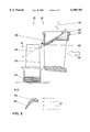
- FIG. 2 shows a version from the Luxtron Corporation, Accufiber Division.
- a black cavity emitter 13 on the tip of the sapphire rod 14 serves as a measuring probe, which is held in the hot gas stream and is heated there.
- the heat radiation is fed outside the hot gas zone, that is to say outside the turbine casing, via an optic coupler 15, into a low temperature fiber 16, is led out from the soundproofing hood and is supplied to a detector 17 having an optic filter 18 and photodiode 19.
- the sapphire tip may also be polished flat and bent, in order to absorb the heat radiation from the desired observation object contactlessly.
- the sapphire rods typically have lengths of up to 0.4 m and diameters of more than 1 mm. They become extremely hot toward the tip. Measurement values are falsified mainly due to characteristic radiation, individual absorption, radiation losses to the cooler environment and the lateral infeed of heat radiation along the freestanding sapphire rod. In the case of the closed embodiment with a cavity 13, measuring errors due to heat conduction in the sapphire rod additionally occur. In unfavorable instances, the measured temperature no longer has much in common with the hot gas or object temperature. Furthermore, in both embodiments, the flow deformation of the rods 14 above 1300° C. presents problems, and because of this flow deformation the sapphire length which can be exposed to the gas flow is limited to less than 10 mm.
- Known pyrometric signal evaluation methods such as are specified, for example, in the manual "Temperaturstrahlung” [Thermal radiation] by W. Pepperhoff, Verlag von Dr. D. Steinkopff, Darmstadt 1956, are used to calculate the temperature from the heat radiation.
- the spectrum of heat radiation for determining temperatures may be evaluated in a monochromatic, bichromatic or wideband manner. Bichromatic pyrometry is useful, above all, for eliminating the influence of variable emissivity of the radiation object.
- the pyrometric sensors mentioned may, in principle, be employed to determine a mean temperature of a row of moving blades or individual temperatures of the individual moving blades.
- the mean temperature is a useful parameter for protecting the gas turbine, for example for limiting the thermal load on the gas turbine by automatic load reduction.
- the individual temperatures are suitable as an early warning of overheating of the moving blades, for example on account of blocked or damaged cooling ducts.
- one object of the invention is to provide a novel high temperature pyrometer which is distinguished by improved high temperature capability, geometric flexibility and measuring accuracy and is particularly suitable for temperature measurements in a gas turbine, a second object is to provide an improved gas turbine with a pyrometer of this type, and a third object is to provide a method for monitoring a gas turbine with the aid of a pyrometer of this type.
- the essence of the invention is a lightguiding measuring probe which comprises a microoptic sensor head for detecting heat radiation and an optic fiber for transmitting the heat radiation to a detector, the sensor head and the fiber having high temperature capability and possessing a pliable sheathing resistant to high temperatures.
- a first exemplary embodiment shows a measuring probe which comprises a microlens and a fiber composed of quartz glass or sapphire crystal, the microlens and fiber being provided with a high temperature coating composed of gold and/or being accommodated in a thin pliable protective capillary composed of Inconel.
- a second and third exemplary embodiment represent a preferred installation of the lightguiding measuring probe in a low pressure guide blade and a high pressure guide blade.
- a fourth exemplary embodiment shows an installation of the measuring probe in a guide blade, in which installation a bore with a blind hole is provided in the blade wall for receiving a sapphire fiber or quartz fiber and the blind hole acts as a microcavity or black cavity emitter.
- One advantage of the pyrometer according to the invention is that, because of its high temperature capability and geometric flexibility, it is particularly suitable for installation in a gas turbine at hot locations where access is difficult.
- the pyrometer can be mounted in the gas turbine at a short distance from the measurement object and at a favorable viewing angle, with the result that measuring accuracy is appreciably improved.
- the moving blade temperatures can be checked and the gas turbine can thereby be improved in terms of temperature distribution over the circumference at the turbine inlet, operating safety, efficiency, maintenance intervals and, overall, reliability and availability.
- FIG. 1 shows a high temperature pyrometer with a viewing channel from Land Instruments International, Inc. (prior art);
- FIG. 2 shows a high temperature pyrometer with a sapphire rod from Luxtron Corporation, Accufiber Division (prior art);
- FIG. 3 shows a high temperature pyrometer according to the invention with a flexible measuring probe which is resistant to high temperatures and has a microoptic sensor head;
- FIG. 4 shows an installation of a pyrometer according to FIG. 3 in a low pressure moving blade
- FIG. 5 shows an installation of a pyrometer according to FIG. 3 in a high pressure moving blade
- FIG. 6 shows an installation of a pyrometer according to FIG. 3 with a microcavity in a guide blade.
- FIG. 3 shows a first exemplary embodiment of a high temperature pyrometer 20 according to the invention.
- the pyrometric or lightguiding measuring probe 21 comprises an optic fiber 24 which has high temperature capability and a microoptic sensor head 22 having high temperature capability, said fiber and said sensor head having a pliable sheathing 25, 26, 27, 28 resistant to high temperatures.
- the microoptic sensor head 22 and the fiber 24 are directly connected optically to one another, that is to say there is no need for any infeed optics in order to transmit light from the sensor head 22 into the fiber 24.
- Heat radiation from a measurement object is detected by the sensor head 22, fed into the fiber 24, transmitted to a detector 32 and converted into at least one electric signal. From the latter, a temperature signal characteristic of the temperature of the measurement object is calculated in measuring electronics 33 with the aid-of known pyrometric signal evaluation methods.
- the microoptic sensor head 22 comprises of one end of the fiber 24, which end may, for example, be polished flat.
- the sensor head 22 is a cone (taper) 22.
- the cone 22 is a microlens 22 with a convex, for example spherical, front face.
- the cone 22 should taper to the fiber diameter. It is also conceivable to lengthen the sensor head 22 toward the fiber 24 by means of a short rodlike light guide, as long as the flexibility and installability of the measuring probe 21 as a whole are not impaired thereby.
- the microlens 22 restricts the numeric aperture or the optic aperture angle of the measuring probe 21, and, due to this constriction of the viewing field, less interfering radiation is received. Moreover, because of the refractive power of the microlens 22, the total heat radiation coming from a measurement object and impinging on the reception area can be fed efficiently into the fiber 24. In particular, for a desired size of the measuring spot and a predetermined object distance range, the focal length of the microlens 22 and the cone length L can be optimized, for example by means of a ray tracing program. Finally, it is important for the sensor head 22 and the fiber 24 to be designed in one piece or to be optically connected to one another in a manner resistant to high temperatures.
- the fiber 24 and the sensor head 22 must consist of a heat resistant material which is transparent for the desired spectral range.
- a suitable choice is silicate glass or quartz glass with a use temperature of up to 1100° C. and with a typical transmission range of 0.3 ⁇ m-2 ⁇ m.
- a standard all-silica glass fiber with a core and envelope (cladding) composed of quartz glass is suitable as a high temperature fiber 24.
- the glass fiber 24 is selected to be multimodal with a stepped index profile and with a core diameter of less than 400 ⁇ m.
- a onepiece version of the cone 22 and fiber 24 can be produced in a known way, for example, from a fiber end by heating and compression or heating and drop formation or, in the case of the production of the fiber 24, by using the cone 22 as a nucleus or by varying the melting speed (feed rate) and drawing speed (pull rate).
- the convex front face may be produced by polishing the cone 22, by laser melting and resolidification of the front face under the action of surface tension or the like.
- the cone 22 or the microlens 22 may be prefabricated, in particular polished, from quartz glass and connected to the fiber 24 via a splice 23, that is to say by electric arc fusion.
- a laser melting method, glass solder or the like may also be used as an alternative optic connecting technique resistant to high temperatures.
- Another advantageous choice of material for the sensor head 22 and the fiber 24 is sapphire crystal with a use temperature of up to approximately 1900° C. and with a typical transmission range of 0.2 ⁇ m-5 ⁇ m. Moreover, due to its chemical inertia, sapphire is distinguished by outstanding longterm resistance, even at high temperatures and in a corrosive environment. It is nowadays possible to obtain pliable monocrystalline sapphire fibers with a diameter of, for example, 300 ⁇ m and a length of up to a few meters.
- the high temperature fiber 24 may be completely or partially such a sapphire fiber.
- a onepiece version of the cone 22 or microlens 22 and the sapphire fiber 24 is obtained, in principle, by means of the methods known from quartz.
- the cone 22 or the microlens 22 may also be bred directly from sapphire crystal and machined by polishing, laser melting, etc. and optically connected to a sapphire fiber 24, for example via glass solder, in a manner resistant to high temperatures.
- Sapphire may also be optically connected to quartz, in particular a sapphire sensor head 22 to a quartz fiber 24, by means of glass solder.
- a measuring probe 21 designed in this way should be protected from corrosion, moisture, mechanical damage, etc.
- a quartz fiber 24 and/or a quartz sensor head 22 is exposed to pronounced corrosion at high temperatures and in a chemically aggressive environment and requires a chemically inert high temperature coating 25, 26 of good adhesion, which may consist of a metal.
- Gold is particularly advantageous up to 750° C. and aluminum up to 550° C. Inward diffusion is too great above these temperatures.
- the sensor head 22 is sheathed with solder 25, a gold or aluminum primer being sputtered on for better adhesion of the solder 25.
- the mechanical protective action of the high temperature coating 25, 26 is somewhat slight. According to the invention, much improved mechanical protection is achieved by means of a protective capillary 27, 28 which preferably consists of a metal, in particular of a heat resistant and corrosion resistant alloy, such as, for example, Inconel.
- the protective capillary 27, 28 is in the form of a small thin tube which, for better pliability, may have a stepped taper toward the sensor head 22.
- the sensor head 22 itself may likewise be surrounded by the protective capillary 27, 28, in particular by a head part 27.
- the head part 27 is fastened to the sensor head 22 via the solder 25, by means of a ceramic high temperature adhesive, by crimping or the like.
- a high temperature coating 25, 26 is likewise possible, particularly since gold and aluminum have high reflectivity in the infrared spectral range.
- sapphire fibers with cladding are also to be expected in future.
- a protective capillary 27, 28 is provided instead of, or in addition to, the high temperature coating 25, 26.
- the possibility of using the measuring probe 21 in difficult measuring environments is markedly improved by the sheathing 25, 26, 27, 28 according to the invention, in particular the high temperature coating 25, 26 and/or the protective capillary 27, 28. It is essential here for the high temperature coating 25, 26 and the protective capillary 27, 28 to be mechanically flexible, in order to preserve the benefits of the pliability of the measuring probe 21. Furthermore, for long fibers 24, a compensating loop 29 is provided in order to compensate the different coefficients of thermal expansion of the fiber 24 and capillary 28.
- the distance to the detector 32 may be bridged by a conventional lengthening fiber 31 and provided with optic connectors 30.
- the high temperature pyrometer according to the invention has significant advantages, as compared with the known prior art.
- the lightguiding measuring probe 21 makes a rigid straight viewing channel 2 or sapphire rod 14 according to FIG. 1 or FIG. 2 superfluous.
- the infeed optics 4, 15 for the low temperature fiber 5, 16 as well as the pressuretight viewing window 3, together with the complicated cooling means and air scavenging system 9 and the heavy mounting flanges, are likewise dispense with at the interface between the high temperature and low temperature regions of the gas turbine.
- the lightguiding measuring probe 21 is distinguished by compactness, high temperature resistance of the components and design, and simple protectability against mechanical and corrosive influences, fiberoptic flexibility being maintained at the same time.
- the measuring probe 21 is also pliable within narrow radii of up to a few cm and can therefore be installed in machines at many locations, even ones where access is difficult. Even extremely hot measurement objects can be observed by means of the microoptic sensor 22 from close proximity and with high local resolution.
- the versatility of the measuring probe 21 according to the invention is also evident from the fact that the detector 32 and the measuring electronics 33 can also supply a spectrometric evaluation of the heat radiation. Falsifications of the spectrum due to nonuniform spectral transmission from the pyrometer 20 can be gauged and corrected.
- the spectrum can, for example, give information on the nature of the surface of the measurement object.
- the optic high temperature pyrometer 20 is particularly suitable for determining radiation temperatures in a gas turbine.
- the measuring probe 21 is arranged in the interior of the gas turbine in order to detect the heat radiation from structural parts subjected to high thermal load, a fiber 24, 31 for transmitting the heat radiation to a detector 32 is provided, preferably outside the gas turbine, and the detector 32 is connected to the measuring electronics 33.
- a particularly useful development or use of the pyrometer 20 concerns accurate interference-insensitive temperature measurement on rotating or stationary turbine blades.
- the measuring probe 21 is seated in a bore 41 in a guide blade 34, 48 preferably of the first or second row.
- the fiber 24, 31, in particular, in the hot gas zone, the high temperature fiber 24, lies at least partially in a cooling duct of the gas turbine.
- a guide tube 43 for receiving the fiber 24, 31 and/or the measuring probe 21 is provided.
- Three preferred embodiments of a pyrometer 20 of this type are illustrated in detail in FIGS. 4 to 6.
- FIG. 4 shows a guide blade 34 and a moving blade 35 preferably of the first or second row of a low pressure gas turbine in a side view and in profile along the section A--A.
- the guide blade 34 is fixed between the blade foot 36 and blade platform 37 and guides the hot gas flow 46 onto the moving blade 35, which is fastened to the rotor 44.
- blade cooling ducts 39 which are supplied with cooling air 40 from the gas turbine cooling ducts (not illustrated), extend between the blade foot 36 and trailing edge 38.
- a bore 41 is made, in particular cast or eroded, in the guide blade 34, said bore having an orifice 42 on a trailing edge 38 of the guide blade 34.
- the sensor head 22 is arranged in the orifice 42 with the viewing direction toward a moving blade 35, in particular toward a leading edge 45 of a moving blade 35.
- the bore 41 preferably runs along the blade cooling ducts 39 and has a guide tube 43 for receiving the measuring probe 21.
- the guide tube 43 has, at the end, a stop which ensures that the sensor head 22 is positioned correctly in the guide blade 34, cooling air 40 flowing through said guide tube.
- holes for the cooling air 40 may be provided in the guide tube 43 for even more efficient cooling of the measuring probe 21 and, at the same time, scavenging of the sensor head 22.
- Different gas turbine walls or gas turbine plenums having different pressure levels can be penetrated in a simple way by the guide tube 43 or its extension (not illustrated) for receiving the fiber 24, 31 and by pressuretight leadthroughs.
- a seal between the guide tube 43 and the protective capillary 28 is provided at the end of the guide tube 43.
- the measuring probe 21 can easily, due to its flexibility and stability, be pushed even into bent guide tubes 43 by distances of up to approximately 6 m.
- the diameter of the measuring probe 21, even with the protective capillary 27, 28, is less than 2 mm and, with the guide tube 43, is 2.5 mm, in contrast to up to 60 mm for a viewing channel 47, indicated by broken lines, for a conventional pyrometer 1.
- Only in this way is it possible to install the high temperature pyrometer 20 according to the invention in a guide blade 34 without any harmful mechanical weakening and to lay the measuring probe 21 in the cooling system of the gas turbine as far as the high temperature zone. Cooling thus takes place without any additional outlay and appreciably increases the life of the pyrometer 20.
- the pyrometer 20 can be exchanged in a simple way, even while the gas turbine is in operation.
- the advantages in terms of measuring accuracy are also significant.
- the measuring probe 21 By installing the measuring probe 21 in a cooled guide blade 34 of a temperature of approximately 600° C., with the surface temperature of the moving blade 35 to be measured being approximately 700° C.-1000° C., the problems due to characteristic radiation and individual absorption of the sensor head 22 and of the high temperature coating 25, 26 composed of gold or the like are largely forced into the background.
- the small area of the microlens 22 and its positioning between the blade cooling ducts 39 ensure highly efficient scavenging and keeping clean by the cooling air 40.
- the measuring spot and the distance to the measurement object are very small or even minimal.
- the viewing direction from the guide blade trailing edge 38 to the moving blade leading edge 45 is essentially perpendicular to the heat-radiating surface observed. This is because, for real nondiffusely scattering surfaces, the angular distribution of the emitted radiation may diverge sharply from Lambert's cosine law and, in particular, fall sharply in a critical angle range above 30°. This behavior is evident, for example, from the manual by R. Siegel and John R. Howell entitled “Thermal Radiation Heat Transfer", Hemisphere Publishing Corporation, Washington (see, for example, page 178). The critical angle range often occurs, in practice, between 60° and 80° and falsifies the temperature measurement due to the variability or indeterminacy of emissivity.
- the pyrometer 20 By means of the pyrometer 20 according to the invention, however, measurement can be carried out as long as the viewing direction is within a cone having an aperture angle of approximately 30° from the perpendicular to the surface of the observed zone of the moving blade 35. In contrast to this, with a conventional viewing channel 47, the viewing angle amounts to 60° and above, which may result in considerable measuring errors.
- FIG. 5 shows a guide blade 48 and a moving blade 49 preferably of the first or second row of a high pressure gas turbine in a side view and shows a moving blade 49 in profile along the section B--B.
- a high temperature pyrometer 20 according to the invention can be integrated in the blade foot 37.
- a bore 41 is provided in a guide blade 48, said bore having an orifice 42 on a rear wall 50 of the blade foot 36 of the guide blade 48.
- the sensor head 22 is arranged in the orifice 42 with the viewing direction toward the moving blade 49.
- the angle of inclination of the bore 41 relative to the hot gas flow direction 46 is still small at approximately 30°, so that the viewing direction 51 of the measuring probe 21 forms small angles to the perpendicular to the surface of the moving blade 49.
- the measuring probe 21 sweeps over a large part of the moving blade 49, in particular the leading edge 45 and the pressure side 52 in the region of the trailing edge.
- the high pressure moving blade 49 can thereby be monitored very accurately with regard to hot zones.
- FIG. 6 shows an embodiment of a high temperature pyrometer 20 for measuring the surface temperature of a guide blade 34, 48.
- the bore 41 is located in a wall of the guide blade 34, 38 as near as possible to the surface where it is made, in particular eroded in, and has a blind hole 53 with a spacer for the sensor head 22.
- the sensor head 22 forms, with the blind hole 53 of the bore 41, a microcavity 54, which acts as a black cavity emitter.
- the measuring probe 21 and the sensor head 22 are, once again, designed as described with regard to FIG. 3.
- the measuring probe 21 preferably comprises a thin monocrystalline sapphire fiber 24 with a very thin protective capillary 28.
- a guide tube 43 is provided only outside the bore 41.
- the spacer may be, for example, a steplike shoulder, a taper of the bore 41, a sleeve or the like. It ensures that a fixed distance of approximately 4-6 mm is maintained between the sensor head 22 and the end of the bore 41.
- the dimensions and design of the microcavity 54 may well differ from the information given.
- the walls of the microcavity 54 are at the temperature to be measured, that is to say, in this case, at least approximately at the surface temperature of a guide blade 34, 48, and that the size and therefore the emissivity of the microcavity 54 are kept constant.
- This pyrometer setup provides an almost ideal black cavity emitter for a near-surface temperature of the guide blade 34, 48.
- a pyrometer 20 designed in this way is distinguished by the advantages mentioned earlier. Furthermore, it is superior to the currently employed high temperature thermocouples in terms of lifetime, signal strength and measuring accuracy. For example, aging effects are low, even at high wall temperatures of approximately 950° C., the signal strength or light energy of the heat radiation increases sharply with the temperature and, by virtue of the contactless measurement method, measuring errors due to heat conduction in the sensor and to very high temperature gradients in the blade wall of up to 300° C./mm are eliminated.
- the pyrometer 20 according to the invention is also suitable for measuring temperatures of other structural parts of a gas turbine, such as, for example, the rotor 44 or the casing surroundings, or for measuring gas temperatures and for measuring temperatures in a gas turbine drive unit.
- the embodiments and installation variants disclosed here can be adapted accordingly for these uses.
- a plurality of pyrometers 20 may also be installed and their heat radiation signals evaluated by common measuring electronics 33. Spectrometric recording of the surface nature is also possible in each case, in addition to or instead of pyrometric temperature determination.
- the subject of the invention is, furthermore, a gas turbine which is suitable, in particular, for generating electric energy and which has a high temperature pyrometer 20 according to the invention, by which the measuring probe 21 for detecting heat radiation from structural parts subjected to high thermal load is arranged in the interior of the gas turbine, of which the fiber 24, 31 is provided for transmitting the heat radiation to a detector 32 and the detector 32 of which is connected to measuring electronics 33.
- the detector 32 is preferably arranged outside the gas turbine.
- An advantageous embodiment relates to a gas turbine with a guide blade 34, 38 having a bore 41 for receiving the measuring probe 21, with a cooling duct which serves for at least partially receiving the fiber 24, 31, and with a guide tube 43 for receiving the fiber 24, 31 and/or the measuring probe 21.
- the bore 41 has an orifice 42 on a trailing edge 38 of the guide blade 34 or on a rear wall 50 of a blade foot 36 of the guide blade 48, and the sensor head 22 is arranged in the orifice 42 with the viewing direction toward a moving blade 35, 49.
- the bore 41 may be located in a wall of the guide blade 34, 48 as near as possible to the surface and may have a blind hole 53, in which a spacer for the sensor head 22 is arranged in such a way that the sensor head 22 forms, with the blind hole 53, a microcavity 54.
- the invention also relates to a method for monitoring a gas turbine with the aid of a high temperature pyrometer 20 according to the invention.
- a precondition is that, as before, the measuring probe 21 is arranged in the interior of the gas turbine in order to detect the heat radiation from structural parts subject to high thermal load, a fiber 24, 31 for transmitting the heat radiation to a detector 32 is provided preferably outside the gas turbine, and the detector 32 is connected to measuring electronics 33.
- a characteristic temperature signal is of at least one structural part subjected to high thermal load is then calculated in the measuring electronics 33 and the temperature signal is used as a protective signal for monitoring the gas turbine.
- Monitoring involves a check of thermal overstressing of the structural part, if required load reduction by throttling the fuel supply, or recording the thermal load history of the structural part in order to estimate its presumed lifetime.
- the monitoring of the temperatures of the moving blades 35, 49 and guide blades 34, 48 particularly of the first and second row is especially important.
- the blades 34, 35, 48, 49 are subjected to such high thermal load that their life may be markedly reduced even by relatively moderate excess temperatures of a few 10° C.
- the risk of such excess temperatures is considerable, however, due to the large temperature difference of a few hundred ° C. between the hot gas and the cooled blades 34, 35, 48, 49.
- individual blades 34, 35, 48, 49 may be overheated because of defects.
- the pyrometer 20 according to the invention by virtue of its improved measuring accuracy, is highly suitable for protecting against this.
- the pyrometer 20 is first calibrated by a comparison measurement by means of a perfect black emitter.
- Absolute temperature measurements at 1000° C, with a measuring accuracy better than ⁇ 10° C., can then be achieved. This means that excess temperatures of blades 34, 35, 48, 49 can be measured with sufficient accuracy and reliability for the first time.
- a mean temperature signal and/or individual temperature signals from moving blades 35, 49 or guide blades 34, 48, in particular a row of moving blades 35, 49 or guide blades 34, 48, is/are preferably used as characteristic temperature signal.
- the pyrometer 20 is also a valuable aid in bringing the blade temperatures nearer to the load limit in a controlled manner during operation and thereby increasing the efficiency of the gas turbine.
- the invention discloses a compact, flexible high temperature pyrometer 20 which is resistant to high temperatures and is intended for installation in hot environments where access is difficult, said pyrometer being particularly useful, on account of its high measuring accuracy, for the protection and increase in output of turbines.
Abstract
Description
Claims (14)
Applications Claiming Priority (2)
| Application Number | Priority Date | Filing Date | Title |
|---|---|---|---|
| DE19736276 | 1997-08-21 | ||
| DE19736276A DE19736276B4 (en) | 1997-08-21 | 1997-08-21 | Optical pyrometer for gas turbines |
Publications (1)
| Publication Number | Publication Date |
|---|---|
| US6109783A true US6109783A (en) | 2000-08-29 |
Family
ID=7839643
Family Applications (1)
| Application Number | Title | Priority Date | Filing Date |
|---|---|---|---|
| US09/137,681 Expired - Lifetime US6109783A (en) | 1997-08-21 | 1998-08-21 | Optic pyrometer for gas turbines |
Country Status (5)
| Country | Link |
|---|---|
| US (1) | US6109783A (en) |
| EP (1) | EP0898158B1 (en) |
| JP (1) | JP4077080B2 (en) |
| CN (1) | CN1145786C (en) |
| DE (2) | DE19736276B4 (en) |
Cited By (54)
| Publication number | Priority date | Publication date | Assignee | Title |
|---|---|---|---|---|
| EP1227222A2 (en) * | 2000-12-28 | 2002-07-31 | General Electric Company | Utilization of pyrometer data to detect oxidation |
| US6513971B2 (en) * | 2000-11-30 | 2003-02-04 | Rolls-Royce Plc | Heatable member and temperature monitor therefor |
| US20040086024A1 (en) * | 2002-11-06 | 2004-05-06 | Sukhwan Choi | Turbine blade (bucket) health monitoring and prognosis using neural network based diagnostic techniques in conjunction with pyrometer signals |
| US20040089810A1 (en) * | 1999-02-08 | 2004-05-13 | General Electric Compamy | System and method for optical monitoring of a combustion flame |
| US20040093147A1 (en) * | 2002-11-12 | 2004-05-13 | Aditya Kumar | Method and system for temperature estimation of gas turbine combustion cans |
| US20040101023A1 (en) * | 2002-11-21 | 2004-05-27 | Sukhwan Choi | Turbine blade (bucket) health monitoring and prognosis using infrared camera |
| US20040179575A1 (en) * | 2003-01-23 | 2004-09-16 | Markham James R. | Instrument for temperature and condition monitoring of advanced turbine blades |
| US20040208470A1 (en) * | 2003-04-17 | 2004-10-21 | Janney Mark A. | Cladding for high temperature optical component and method of making same |
| US20050198967A1 (en) * | 2002-09-23 | 2005-09-15 | Siemens Westinghouse Power Corp. | Smart component for use in an operating environment |
| US20050287386A1 (en) * | 2002-09-23 | 2005-12-29 | Siemens Westinghouse Power Corporation | Method of instrumenting a component |
| US20060056960A1 (en) * | 2002-09-23 | 2006-03-16 | Siemens Westinghouse Power Corporation | Apparatus and method of detecting wear in an abradable coating system |
| US20060056959A1 (en) * | 2002-09-23 | 2006-03-16 | Siemens Westinghouse Power Corporation | Apparatus and method of monitoring operating parameters of a gas turbine |
| US7014359B2 (en) * | 2001-03-13 | 2006-03-21 | Yokogawa Denshikiki Co., Ltd. | Temperature measuring device |
| US7033070B2 (en) | 2000-06-26 | 2006-04-25 | Nec Corporation | Method and apparatus for measuring temperature |
| EP1835150A1 (en) * | 2006-03-17 | 2007-09-19 | Siemens Aktiengesellschaft | Method for inspecting a turbine plant and device therefor |
| US20070258807A1 (en) * | 2006-05-04 | 2007-11-08 | Siemens Power Generation, Inc. | Infrared-based method and apparatus for online detection of cracks in steam turbine components |
| EP1854961A2 (en) * | 2006-05-11 | 2007-11-14 | Rolls-Royce Plc | Clearance control apparatus |
| US20070290131A1 (en) * | 2006-05-22 | 2007-12-20 | General Electric Company | Multiwavelength pyrometry systems |
| US20080054645A1 (en) * | 2006-09-06 | 2008-03-06 | Siemens Power Generation, Inc. | Electrical assembly for monitoring conditions in a combustion turbine operating environment |
| US20080245980A1 (en) * | 2007-04-05 | 2008-10-09 | Siemens Power Generation, Inc. | Monitoring system for turbine engine |
| WO2009138399A1 (en) * | 2008-05-14 | 2009-11-19 | Centre de Recherches Métallurgiques asbl - Centrum voor Research in de Metallurgie vzw | Libs measurement head optimized for the analysis of liquid compounds and/or compounds at high temperatures |
| US20090297336A1 (en) * | 2007-08-21 | 2009-12-03 | General Electric Company | Online systems and methods for thermal inspection of parts |
| US20090312956A1 (en) * | 1999-12-22 | 2009-12-17 | Zombo Paul J | Method and apparatus for measuring on-line failure of turbine thermal barrier coatings |
| US20100047058A1 (en) * | 2008-08-25 | 2010-02-25 | General Electric Company, A New York Corporation | System and method for temperature sensing in turbines |
| US20100117859A1 (en) * | 2004-06-21 | 2010-05-13 | Mitchell David J | Apparatus and Method of Monitoring Operating Parameters of a Gas Turbine |
| US20100226757A1 (en) * | 2006-09-14 | 2010-09-09 | Siemens Power Generation, Inc. | Instrumented component for combustion turbine engine |
| US20100226756A1 (en) * | 2004-06-21 | 2010-09-09 | Siemens Power Generation, Inc. | Instrumented component for use in an operating environment |
| US20110128989A1 (en) * | 2009-11-30 | 2011-06-02 | General Electric Company | Multiwavelength thermometer |
| US20110133949A1 (en) * | 2007-11-08 | 2011-06-09 | Ramesh Subramanian | Instrumented component for wireless telemetry |
| US20110133950A1 (en) * | 2007-11-08 | 2011-06-09 | Ramesh Subramanian | Instrumented component for wireless telemetry |
| US20110231110A1 (en) * | 2010-03-16 | 2011-09-22 | Johnston Robert T | Fiber Optic Sensor System for Detecting Surface Wear |
| US8151623B2 (en) | 2002-09-23 | 2012-04-10 | Siemens Energy, Inc. | Sensor for quantifying widening reduction wear on a surface |
| US20120098940A1 (en) * | 2010-10-21 | 2012-04-26 | Zombo Paul J | Method for monitoring a high-temperature region of interest in a turbine engine |
| US20120096961A1 (en) * | 2010-10-21 | 2012-04-26 | General Electric Company | Probe holder for turbine engine sensor |
| US20120096946A1 (en) * | 2010-10-21 | 2012-04-26 | General Electric Company | Sensor packaging for turbine engine |
| US20120128468A1 (en) * | 2010-11-22 | 2012-05-24 | Kurt Kramer Schleif | Sensor assembly for use with a turbomachine and methods of assembling same |
| US8292501B1 (en) * | 2008-05-13 | 2012-10-23 | Florida Turbine Technologies, Inc. | Turbopump with cavitation detection |
| US8413493B1 (en) | 2011-12-12 | 2013-04-09 | Florida Turbine Technologies, Inc. | Method for detecting a defect on an operating turbine rotor blade |
| US20130122594A1 (en) * | 2011-11-10 | 2013-05-16 | Rolls-Royce Plc | Determination of component temperature |
| US8519866B2 (en) | 2007-11-08 | 2013-08-27 | Siemens Energy, Inc. | Wireless telemetry for instrumented component |
| US20140133994A1 (en) * | 2011-06-21 | 2014-05-15 | Siemens Aktiengesellschaft | Gas turbine with pyrometer |
| RU2521217C1 (en) * | 2012-12-26 | 2014-06-27 | Федеральное бюджетное учреждение "12 Центральный научно-исследовательский институт Министерства обороны Российской Федерации" | Method of measuring temperature profile in structural materials |
| US20140376589A1 (en) * | 2013-06-24 | 2014-12-25 | General Electric Company | Optical monitoring system for a gas turbine engine |
| US20150003965A1 (en) * | 2011-08-29 | 2015-01-01 | Siemens Aktiengesellschaft | Turbomachine for generating power having a temperature measurement device in a region of the rotor |
| US20150110154A1 (en) * | 2013-10-22 | 2015-04-23 | Rosemount Aerospace Inc. | Temperature sensors |
| US9325388B2 (en) | 2012-06-21 | 2016-04-26 | Siemens Energy, Inc. | Wireless telemetry system including an induction power system |
| US9420356B2 (en) | 2013-08-27 | 2016-08-16 | Siemens Energy, Inc. | Wireless power-receiving assembly for a telemetry system in a high-temperature environment of a combustion turbine engine |
| EP3363996A1 (en) | 2017-02-16 | 2018-08-22 | Ansaldo Energia Switzerland AG | Blade assembly for gas turbine engines and gas turbine engine incorporating said blade assembly |
| US10508954B2 (en) | 2016-08-08 | 2019-12-17 | Ansaldo Energia Switzerland AG | Temperature detecting device for a gas turbine power plant and gas turbine power plant comprising said temperature detecting device |
| US10520371B2 (en) | 2015-10-22 | 2019-12-31 | Applied Materials, Inc. | Optical fiber temperature sensors, temperature monitoring apparatus, and manufacturing methods |
| US10871403B1 (en) | 2019-09-23 | 2020-12-22 | Kidde Technologies, Inc. | Aircraft temperature sensor |
| US11466979B2 (en) * | 2020-02-17 | 2022-10-11 | University Of Electronic Science And Technology Of China | Method of measuring longitude deformation of blades by differential radiation between blades and casing |
| EP4116545A1 (en) * | 2021-07-05 | 2023-01-11 | Siemens Energy Global GmbH & Co. KG | Continuous flow engine measurement arrangement |
| CN115979345A (en) * | 2022-12-30 | 2023-04-18 | 共青科技职业学院 | Artificial intelligence prediction system and prediction method for residual life of marine gas turbine blade |
Families Citing this family (26)
| Publication number | Priority date | Publication date | Assignee | Title |
|---|---|---|---|---|
| WO2001046660A1 (en) * | 1999-12-22 | 2001-06-28 | Siemens Westinghouse Power Corporation | Method and apparatus for measuring on line failure of turbine thermal barrier coatings |
| JP4616456B2 (en) * | 2000-10-31 | 2011-01-19 | 株式会社ヘリオス | Immersion type optical fiber radiation thermometer for measuring molten metal temperature and method for measuring temperature of molten metal |
| DE50112904D1 (en) | 2000-12-16 | 2007-10-04 | Alstom Technology Ltd | Method for operating a premix burner |
| DE10148035B4 (en) * | 2001-09-28 | 2004-12-09 | Karakas, Erdogan, Dr.-Ing. | Device for resistance welding workpieces |
| US6980708B2 (en) | 2002-05-13 | 2005-12-27 | Bartec Gmbh | Device for fibre optic temperature measurement with an optical fibre |
| EP1696102B1 (en) * | 2005-02-28 | 2015-07-29 | Siemens Aktiengesellschaft | Gas turbine and method of monitoring the operation of such a gasturbine |
| DE102005047739B3 (en) | 2005-09-29 | 2007-02-08 | Siemens Ag | Substrate with matrix layer for turbine systems and production process has multilayer of and or encapsulated nanoparticles that release a colored material above a threshold temperature |
| DE602006012386D1 (en) * | 2006-11-29 | 2010-04-01 | Abb Research Ltd | DEVICE AND METHOD FOR PROCESSING AND / OR ANALYZING RADIATION REPRESENTING PICTURE INFORMATION |
| DE102008022571A1 (en) * | 2008-05-07 | 2010-02-25 | Siemens Aktiengesellschaft | Temperature measurement on parts of a turbomachine |
| EP2385233A1 (en) * | 2010-05-07 | 2011-11-09 | Alstom Technology Ltd | Method for the operation of a gas turbine unit based on the combustor wall temperature |
| US8650883B2 (en) * | 2010-08-11 | 2014-02-18 | General Electric Company | System and method for operating a gas turbine |
| US8678644B2 (en) * | 2011-08-16 | 2014-03-25 | General Electric Company | Hot gas path measurement |
| US8998569B2 (en) * | 2011-08-17 | 2015-04-07 | United Technologies Corporation | Gas turbine engine internal compartment structure having egress feature |
| EP2568583B1 (en) | 2011-09-12 | 2016-07-27 | ALSTOM Renewable Technologies | Temperature monitoring device for electric motor |
| AT514454B1 (en) | 2013-07-11 | 2015-03-15 | Engel Austria Gmbh | heater |
| KR101450651B1 (en) * | 2013-11-27 | 2014-10-15 | 우진 일렉트로나이트(주) | Continuous Temperature Sensor and RH apparatus including it |
| CN106483266B (en) * | 2015-08-26 | 2019-02-12 | 深圳市燃气集团股份有限公司 | A kind of underground electronic tag survey meter of detectable fuel gas |
| EP3336497A1 (en) * | 2016-12-13 | 2018-06-20 | Siemens Aktiengesellschaft | Gas turbine blade with integrated pyrometer probe |
| US10451484B2 (en) | 2017-01-12 | 2019-10-22 | General Electric Company | Temperature sensor system and method |
| CN107701514A (en) * | 2017-09-30 | 2018-02-16 | 中国航发沈阳发动机研究所 | Stator blade structure is measured between compressor stage |
| CN108387248A (en) * | 2018-05-11 | 2018-08-10 | 南京工程学院 | A kind of fibre optical sensor with gaseous film control |
| US11639872B1 (en) * | 2019-04-30 | 2023-05-02 | Ge Inspection Technologies, Lp | Combustion monitoring system |
| CN112326172A (en) * | 2020-11-23 | 2021-02-05 | 华能国际电力股份有限公司 | Cooling device of gas turbine moving blade non-contact vibration measurement sensor |
| AT524986A1 (en) * | 2021-04-23 | 2022-11-15 | Avl List Gmbh | MEASUREMENT ARRANGEMENT |
| CN113916170A (en) * | 2021-09-03 | 2022-01-11 | 中国航发哈尔滨东安发动机有限公司 | Curved probe for measuring long and narrow inner cavity |
| DE102022124934A1 (en) | 2022-09-28 | 2024-03-28 | Voith Patent Gmbh | Gearbox device with temperature measurement |
Citations (6)
| Publication number | Priority date | Publication date | Assignee | Title |
|---|---|---|---|---|
| US3584509A (en) * | 1968-10-01 | 1971-06-15 | Int Harvester Co | Temperature measuring apparatus and methods |
| WO1986000131A1 (en) * | 1984-06-08 | 1986-01-03 | The Dow Chemical Company | Optical pyrometer sight tube assembly for controlling a gas turbine |
| JPS61200437A (en) * | 1985-03-01 | 1986-09-05 | Hitachi Ltd | Apparatus for measuring temperature of turbine rotor |
| US5366290A (en) * | 1990-10-17 | 1994-11-22 | Ametek, Inc. | High temperature optical probe |
| US5507576A (en) * | 1993-04-01 | 1996-04-16 | European Gas Turbines Sa | Bichromatic pyrometer |
| US5652653A (en) * | 1994-05-27 | 1997-07-29 | Eastman Chemical Company | On-line quantitative analysis of chemical compositions by Raman spectrometry |
Family Cites Families (10)
| Publication number | Priority date | Publication date | Assignee | Title |
|---|---|---|---|---|
| US4533243A (en) * | 1980-07-31 | 1985-08-06 | Institut Problem Litiya Akademii Nauk Ukrainskoi Ssr | Light guide for transmitting thermal radiation from melt to pyrometer and method of measuring temperature of molten metal in metallurgical vessel with the aid of said light guide |
| DE3050539C2 (en) * | 1980-08-22 | 1986-10-18 | Institut problem lit'ja Akademii Nauk Ukrainskoj SSR, Kiev | Optical fiber arrangement for transferring the heat radiation from a melt to a pyrometer |
| DE3321028A1 (en) * | 1982-06-17 | 1983-12-22 | Smiths Industries Public Ltd. Co., London | OPTICAL COMPONENT |
| GB8330813D0 (en) * | 1983-11-18 | 1983-12-29 | Smiths Industries Plc | Fibre-optic cable assemblies |
| AT389389B (en) * | 1985-09-18 | 1989-11-27 | Tiroler Roehren & Metallwerk | DEVICE FOR PHOTOELECTRIC TEMPERATURE MEASUREMENT OF A MEASURED OBJECT |
| GB8629492D0 (en) * | 1986-12-10 | 1987-01-21 | Smiths Industries Plc | Optical radiation sensor apparatus |
| GB9020219D0 (en) * | 1990-09-15 | 1990-10-24 | Smiths Industries Plc | Optical temperature sensors |
| US5164999A (en) * | 1991-05-20 | 1992-11-17 | Johnson Matthey, Inc. | Blackbody fired on silica fiber |
| US5364186A (en) * | 1992-04-28 | 1994-11-15 | Luxtron Corporation | Apparatus and method for monitoring a temperature using a thermally fused composite ceramic blackbody temperature probe |
| DE19549214C2 (en) * | 1995-12-30 | 1999-11-04 | Ego Elektro Geraetebau Gmbh | Temperature sensor unit |
-
1997
- 1997-08-21 DE DE19736276A patent/DE19736276B4/en not_active Revoked
-
1998
- 1998-07-31 DE DE59813274T patent/DE59813274D1/en not_active Expired - Lifetime
- 1998-07-31 EP EP98810744A patent/EP0898158B1/en not_active Expired - Lifetime
- 1998-08-21 CN CNB981186203A patent/CN1145786C/en not_active Expired - Lifetime
- 1998-08-21 US US09/137,681 patent/US6109783A/en not_active Expired - Lifetime
- 1998-08-21 JP JP23557298A patent/JP4077080B2/en not_active Expired - Fee Related
Patent Citations (6)
| Publication number | Priority date | Publication date | Assignee | Title |
|---|---|---|---|---|
| US3584509A (en) * | 1968-10-01 | 1971-06-15 | Int Harvester Co | Temperature measuring apparatus and methods |
| WO1986000131A1 (en) * | 1984-06-08 | 1986-01-03 | The Dow Chemical Company | Optical pyrometer sight tube assembly for controlling a gas turbine |
| JPS61200437A (en) * | 1985-03-01 | 1986-09-05 | Hitachi Ltd | Apparatus for measuring temperature of turbine rotor |
| US5366290A (en) * | 1990-10-17 | 1994-11-22 | Ametek, Inc. | High temperature optical probe |
| US5507576A (en) * | 1993-04-01 | 1996-04-16 | European Gas Turbines Sa | Bichromatic pyrometer |
| US5652653A (en) * | 1994-05-27 | 1997-07-29 | Eastman Chemical Company | On-line quantitative analysis of chemical compositions by Raman spectrometry |
Non-Patent Citations (6)
| Title |
|---|
| "Temperaturstrahlung," by W. Pepperhoff, Verlag Dr. D. Steinkopff, Darmstadt (1956) (title page only). |
| Land Application Dedicated Product: "Turbine Blade Temperature Measurement system," Land Instruments International. |
| Land Application Dedicated Product: Turbine Blade Temperature Measurement system, Land Instruments International. * |
| Technical Specification, "Accufiber Thermometer, Model 10 High Temperature Measurement and Control System and Accessories," Luxtron Corp., copyright 1987-1991. |
| Technical Specification, Accufiber Thermometer, Model 10 High Temperature Measurement and Control System and Accessories, Luxtron Corp., copyright 1987 1991. * |
| Temperaturstrahlung, by W. Pepperhoff, Verlag Dr. D. Steinkopff, Darmstadt (1956) (title page only). * |
Cited By (89)
| Publication number | Priority date | Publication date | Assignee | Title |
|---|---|---|---|---|
| US7112796B2 (en) | 1999-02-08 | 2006-09-26 | General Electric Company | System and method for optical monitoring of a combustion flame |
| US20040089810A1 (en) * | 1999-02-08 | 2004-05-13 | General Electric Compamy | System and method for optical monitoring of a combustion flame |
| US7690840B2 (en) | 1999-12-22 | 2010-04-06 | Siemens Energy, Inc. | Method and apparatus for measuring on-line failure of turbine thermal barrier coatings |
| US20090312956A1 (en) * | 1999-12-22 | 2009-12-17 | Zombo Paul J | Method and apparatus for measuring on-line failure of turbine thermal barrier coatings |
| US7033070B2 (en) | 2000-06-26 | 2006-04-25 | Nec Corporation | Method and apparatus for measuring temperature |
| US6513971B2 (en) * | 2000-11-30 | 2003-02-04 | Rolls-Royce Plc | Heatable member and temperature monitor therefor |
| EP1227222A2 (en) * | 2000-12-28 | 2002-07-31 | General Electric Company | Utilization of pyrometer data to detect oxidation |
| EP1227222A3 (en) * | 2000-12-28 | 2004-01-02 | General Electric Company | Utilization of pyrometer data to detect oxidation |
| US6579005B2 (en) * | 2000-12-28 | 2003-06-17 | General Electric Company | Utilization of pyrometer data to detect oxidation |
| US7014359B2 (en) * | 2001-03-13 | 2006-03-21 | Yokogawa Denshikiki Co., Ltd. | Temperature measuring device |
| US20050198967A1 (en) * | 2002-09-23 | 2005-09-15 | Siemens Westinghouse Power Corp. | Smart component for use in an operating environment |
| US7618712B2 (en) | 2002-09-23 | 2009-11-17 | Siemens Energy, Inc. | Apparatus and method of detecting wear in an abradable coating system |
| US7572524B2 (en) | 2002-09-23 | 2009-08-11 | Siemens Energy, Inc. | Method of instrumenting a component |
| US8151623B2 (en) | 2002-09-23 | 2012-04-10 | Siemens Energy, Inc. | Sensor for quantifying widening reduction wear on a surface |
| US20050287386A1 (en) * | 2002-09-23 | 2005-12-29 | Siemens Westinghouse Power Corporation | Method of instrumenting a component |
| US20060056960A1 (en) * | 2002-09-23 | 2006-03-16 | Siemens Westinghouse Power Corporation | Apparatus and method of detecting wear in an abradable coating system |
| US20060056959A1 (en) * | 2002-09-23 | 2006-03-16 | Siemens Westinghouse Power Corporation | Apparatus and method of monitoring operating parameters of a gas turbine |
| US7582359B2 (en) | 2002-09-23 | 2009-09-01 | Siemens Energy, Inc. | Apparatus and method of monitoring operating parameters of a gas turbine |
| US20040086024A1 (en) * | 2002-11-06 | 2004-05-06 | Sukhwan Choi | Turbine blade (bucket) health monitoring and prognosis using neural network based diagnostic techniques in conjunction with pyrometer signals |
| US6786635B2 (en) * | 2002-11-06 | 2004-09-07 | General Electric Company | Turbine blade (bucket) health monitoring and prognosis using neural network based diagnostic techniques in conjunction with pyrometer signals |
| US20040093147A1 (en) * | 2002-11-12 | 2004-05-13 | Aditya Kumar | Method and system for temperature estimation of gas turbine combustion cans |
| US20040101023A1 (en) * | 2002-11-21 | 2004-05-27 | Sukhwan Choi | Turbine blade (bucket) health monitoring and prognosis using infrared camera |
| US6796709B2 (en) * | 2002-11-21 | 2004-09-28 | General Electric Company | Turbine blade (bucket) health monitoring and prognosis using infrared camera |
| US20040179575A1 (en) * | 2003-01-23 | 2004-09-16 | Markham James R. | Instrument for temperature and condition monitoring of advanced turbine blades |
| US20040208470A1 (en) * | 2003-04-17 | 2004-10-21 | Janney Mark A. | Cladding for high temperature optical component and method of making same |
| US6968114B2 (en) | 2003-04-17 | 2005-11-22 | Ut-Battelle, Llc | Cladding for high temperature optical component and method of making same |
| US8742944B2 (en) * | 2004-06-21 | 2014-06-03 | Siemens Energy, Inc. | Apparatus and method of monitoring operating parameters of a gas turbine |
| US8004423B2 (en) | 2004-06-21 | 2011-08-23 | Siemens Energy, Inc. | Instrumented component for use in an operating environment |
| US20100117859A1 (en) * | 2004-06-21 | 2010-05-13 | Mitchell David J | Apparatus and Method of Monitoring Operating Parameters of a Gas Turbine |
| US20100226756A1 (en) * | 2004-06-21 | 2010-09-09 | Siemens Power Generation, Inc. | Instrumented component for use in an operating environment |
| WO2007107395A1 (en) * | 2006-03-17 | 2007-09-27 | Siemens Aktiengesellschaft | Method for inspecting a turbine installation and corresponding device |
| US8322202B2 (en) | 2006-03-17 | 2012-12-04 | Siemens Aktiengesellschaft | Method for inspecting a turbine installation and corresponding device |
| EP1835150A1 (en) * | 2006-03-17 | 2007-09-19 | Siemens Aktiengesellschaft | Method for inspecting a turbine plant and device therefor |
| US20090293596A1 (en) * | 2006-03-17 | 2009-12-03 | Ulrich Ehehalt | Method for Inspecting a Turbine Installation and Corresponding Device |
| US7432505B2 (en) | 2006-05-04 | 2008-10-07 | Siemens Power Generation, Inc. | Infrared-based method and apparatus for online detection of cracks in steam turbine components |
| US20070258807A1 (en) * | 2006-05-04 | 2007-11-08 | Siemens Power Generation, Inc. | Infrared-based method and apparatus for online detection of cracks in steam turbine components |
| US7819623B2 (en) * | 2006-05-11 | 2010-10-26 | Rolls-Royce Plc | Clearance control apparatus |
| EP1854961A3 (en) * | 2006-05-11 | 2012-10-17 | Rolls-Royce Plc | Clearance control apparatus |
| EP1854961A2 (en) * | 2006-05-11 | 2007-11-14 | Rolls-Royce Plc | Clearance control apparatus |
| US20080063509A1 (en) * | 2006-05-11 | 2008-03-13 | Sutherland Roger A | Clearance control apparatus |
| US20070290131A1 (en) * | 2006-05-22 | 2007-12-20 | General Electric Company | Multiwavelength pyrometry systems |
| US7633066B2 (en) | 2006-05-22 | 2009-12-15 | General Electric Company | Multiwavelength pyrometry systems |
| US20080054645A1 (en) * | 2006-09-06 | 2008-03-06 | Siemens Power Generation, Inc. | Electrical assembly for monitoring conditions in a combustion turbine operating environment |
| US7368827B2 (en) | 2006-09-06 | 2008-05-06 | Siemens Power Generation, Inc. | Electrical assembly for monitoring conditions in a combustion turbine operating environment |
| US7969323B2 (en) | 2006-09-14 | 2011-06-28 | Siemens Energy, Inc. | Instrumented component for combustion turbine engine |
| US20100226757A1 (en) * | 2006-09-14 | 2010-09-09 | Siemens Power Generation, Inc. | Instrumented component for combustion turbine engine |
| US7486864B2 (en) * | 2007-04-05 | 2009-02-03 | Siemens Energy, Inc. | Monitoring system for turbine engine |
| US20080245980A1 (en) * | 2007-04-05 | 2008-10-09 | Siemens Power Generation, Inc. | Monitoring system for turbine engine |
| US20090297336A1 (en) * | 2007-08-21 | 2009-12-03 | General Electric Company | Online systems and methods for thermal inspection of parts |
| US8797179B2 (en) | 2007-11-08 | 2014-08-05 | Siemens Aktiengesellschaft | Instrumented component for wireless telemetry |
| US9071888B2 (en) | 2007-11-08 | 2015-06-30 | Siemens Aktiengesellschaft | Instrumented component for wireless telemetry |
| US8519866B2 (en) | 2007-11-08 | 2013-08-27 | Siemens Energy, Inc. | Wireless telemetry for instrumented component |
| US20110133949A1 (en) * | 2007-11-08 | 2011-06-09 | Ramesh Subramanian | Instrumented component for wireless telemetry |
| US20110133950A1 (en) * | 2007-11-08 | 2011-06-09 | Ramesh Subramanian | Instrumented component for wireless telemetry |
| US8292501B1 (en) * | 2008-05-13 | 2012-10-23 | Florida Turbine Technologies, Inc. | Turbopump with cavitation detection |
| BE1018123A3 (en) * | 2008-05-14 | 2010-05-04 | Ct Rech Metallurgiques Asbl | LIBS-TYPE MEASURING HEAD OPTIMIZED FOR THE ANALYSIS OF LIQUID AND / OR HIGH TEMPERATURE COMPOUNDS. |
| WO2009138399A1 (en) * | 2008-05-14 | 2009-11-19 | Centre de Recherches Métallurgiques asbl - Centrum voor Research in de Metallurgie vzw | Libs measurement head optimized for the analysis of liquid compounds and/or compounds at high temperatures |
| US20100047058A1 (en) * | 2008-08-25 | 2010-02-25 | General Electric Company, A New York Corporation | System and method for temperature sensing in turbines |
| US20110128989A1 (en) * | 2009-11-30 | 2011-06-02 | General Electric Company | Multiwavelength thermometer |
| US8790006B2 (en) | 2009-11-30 | 2014-07-29 | General Electric Company | Multiwavelength thermometer |
| US8571813B2 (en) | 2010-03-16 | 2013-10-29 | Siemens Energy, Inc. | Fiber optic sensor system for detecting surface wear |
| US20110231110A1 (en) * | 2010-03-16 | 2011-09-22 | Johnston Robert T | Fiber Optic Sensor System for Detecting Surface Wear |
| US20120096961A1 (en) * | 2010-10-21 | 2012-04-26 | General Electric Company | Probe holder for turbine engine sensor |
| US9015002B2 (en) | 2010-10-21 | 2015-04-21 | Siemens Energy, Inc. | System for monitoring a high-temperature region of interest in a turbine engine |
| US20120096946A1 (en) * | 2010-10-21 | 2012-04-26 | General Electric Company | Sensor packaging for turbine engine |
| US10704958B2 (en) * | 2010-10-21 | 2020-07-07 | Siemens Energy, Inc. | Method for monitoring a high-temperature region of interest in a turbine engine |
| US20120098940A1 (en) * | 2010-10-21 | 2012-04-26 | Zombo Paul J | Method for monitoring a high-temperature region of interest in a turbine engine |
| KR20130118885A (en) * | 2010-10-21 | 2013-10-30 | 지멘스 에너지, 인코포레이티드 | Method for monitoring a high-temperature region of interest in a turbine engine |
| US8998568B2 (en) * | 2010-10-21 | 2015-04-07 | General Electric Company | Sensor packaging for turbine engine |
| US20120128468A1 (en) * | 2010-11-22 | 2012-05-24 | Kurt Kramer Schleif | Sensor assembly for use with a turbomachine and methods of assembling same |
| US20140133994A1 (en) * | 2011-06-21 | 2014-05-15 | Siemens Aktiengesellschaft | Gas turbine with pyrometer |
| US20150003965A1 (en) * | 2011-08-29 | 2015-01-01 | Siemens Aktiengesellschaft | Turbomachine for generating power having a temperature measurement device in a region of the rotor |
| US20130122594A1 (en) * | 2011-11-10 | 2013-05-16 | Rolls-Royce Plc | Determination of component temperature |
| US8413493B1 (en) | 2011-12-12 | 2013-04-09 | Florida Turbine Technologies, Inc. | Method for detecting a defect on an operating turbine rotor blade |
| US9325388B2 (en) | 2012-06-21 | 2016-04-26 | Siemens Energy, Inc. | Wireless telemetry system including an induction power system |
| RU2521217C1 (en) * | 2012-12-26 | 2014-06-27 | Федеральное бюджетное учреждение "12 Центральный научно-исследовательский институт Министерства обороны Российской Федерации" | Method of measuring temperature profile in structural materials |
| US20140376589A1 (en) * | 2013-06-24 | 2014-12-25 | General Electric Company | Optical monitoring system for a gas turbine engine |
| US9482596B2 (en) * | 2013-06-24 | 2016-11-01 | General Electric Company | Optical monitoring system for a gas turbine engine |
| US9420356B2 (en) | 2013-08-27 | 2016-08-16 | Siemens Energy, Inc. | Wireless power-receiving assembly for a telemetry system in a high-temperature environment of a combustion turbine engine |
| US9689755B2 (en) * | 2013-10-22 | 2017-06-27 | Rosemount Aerospace Inc. | Temperature sensors |
| US20150110154A1 (en) * | 2013-10-22 | 2015-04-23 | Rosemount Aerospace Inc. | Temperature sensors |
| US10520371B2 (en) | 2015-10-22 | 2019-12-31 | Applied Materials, Inc. | Optical fiber temperature sensors, temperature monitoring apparatus, and manufacturing methods |
| US10508954B2 (en) | 2016-08-08 | 2019-12-17 | Ansaldo Energia Switzerland AG | Temperature detecting device for a gas turbine power plant and gas turbine power plant comprising said temperature detecting device |
| EP3363996A1 (en) | 2017-02-16 | 2018-08-22 | Ansaldo Energia Switzerland AG | Blade assembly for gas turbine engines and gas turbine engine incorporating said blade assembly |
| US10871403B1 (en) | 2019-09-23 | 2020-12-22 | Kidde Technologies, Inc. | Aircraft temperature sensor |
| US11466979B2 (en) * | 2020-02-17 | 2022-10-11 | University Of Electronic Science And Technology Of China | Method of measuring longitude deformation of blades by differential radiation between blades and casing |
| EP4116545A1 (en) * | 2021-07-05 | 2023-01-11 | Siemens Energy Global GmbH & Co. KG | Continuous flow engine measurement arrangement |
| CN115979345A (en) * | 2022-12-30 | 2023-04-18 | 共青科技职业学院 | Artificial intelligence prediction system and prediction method for residual life of marine gas turbine blade |
| CN115979345B (en) * | 2022-12-30 | 2023-09-22 | 共青科技职业学院 | Artificial intelligence marine gas turbine blade residual life prediction system and prediction method |
Also Published As
| Publication number | Publication date |
|---|---|
| EP0898158A3 (en) | 2000-04-05 |
| DE19736276A1 (en) | 1999-02-25 |
| CN1145786C (en) | 2004-04-14 |
| EP0898158A2 (en) | 1999-02-24 |
| CN1210256A (en) | 1999-03-10 |
| JP4077080B2 (en) | 2008-04-16 |
| DE19736276B4 (en) | 2006-07-27 |
| DE59813274D1 (en) | 2006-01-19 |
| EP0898158B1 (en) | 2005-12-14 |
| JPH11142247A (en) | 1999-05-28 |
Similar Documents
| Publication | Publication Date | Title |
|---|---|---|
| US6109783A (en) | Optic pyrometer for gas turbines | |
| US4576486A (en) | Optical fiber thermometer | |
| AU564325B2 (en) | Optical pyrometer sight tube assembly for controlling a gas turbine | |
| CN101886955B (en) | Fiber Bragg grating sensing package and system for gas turbine temperature measurement | |
| US4408827A (en) | Imaging system for hostile environment optical probe | |
| US5201227A (en) | Device for measuring vibrations on rotating blade | |
| US9518894B2 (en) | Device for measuring vibration amplitudes of the blade tips in a turbomachine | |
| US5180227A (en) | Optical temperature sensors | |
| JP4429705B2 (en) | Distance measuring method and distance measuring device | |
| JPH03206927A (en) | High temperature sensor | |
| US5211478A (en) | Housing for temperature measuring apparatus | |
| US6513971B2 (en) | Heatable member and temperature monitor therefor | |
| US4955979A (en) | Optical pyrometer with at least one fibre | |
| CA2156204A1 (en) | High resolution temperature sensing device | |
| Claggett et al. | Radiation and infrared pyrometers | |
| CN105698940B (en) | A kind of temperature-measuring gun and temp measuring system for high temperature fluent metal | |
| Cielo et al. | Conical-cavity fiber optic sensor for temperature measurement in a steel furnace | |
| JPH04120429A (en) | Vibration measuring apparatus for rotor blade | |
| Miller et al. | Optical sensors for turbine engine applications | |
| Rooth et al. | Dual wavelength temperature monitoring of TBC coated Alstom 13E2 turbine blades | |
| CA1319832C (en) | Infrared radiation probe for measuring the temperature of low-emissivity materials in a production line | |
| CN113758599A (en) | Optical fiber method-amber total temperature probe for dynamic total temperature measurement and manufacturing method thereof | |
| JPH0816628B2 (en) | High temperature gas thermometer | |
| KR101016452B1 (en) | Up-down moving pyrometer system for reheating furnace | |
| Campbell | Use of fiber optics in industrial infrared thermometry |
Legal Events
| Date | Code | Title | Description |
|---|---|---|---|
| AS | Assignment |
Owner name: ABB RESEARCH LTD., SWITZERLAND Free format text: ASSIGNMENT OF ASSIGNORS INTEREST;ASSIGNORS:DOBLER, THOMAS;EVERS, WOLFGANG;HAFFNER, KEN;REEL/FRAME:010833/0660 Effective date: 19980817 |
|
| STCF | Information on status: patent grant |
Free format text: PATENTED CASE |
|
| FEPP | Fee payment procedure |
Free format text: PAYOR NUMBER ASSIGNED (ORIGINAL EVENT CODE: ASPN); ENTITY STATUS OF PATENT OWNER: LARGE ENTITY |
|
| FPAY | Fee payment |
Year of fee payment: 4 |
|
| AS | Assignment |
Owner name: ALSTOM TECHNOLOGY LTD, SWITZERLAND Free format text: ASSIGNMENT OF ASSIGNORS INTEREST;ASSIGNOR:ABB RESEARCH LTD;REEL/FRAME:015487/0597 Effective date: 20040503 |
|
| FPAY | Fee payment |
Year of fee payment: 8 |
|
| FPAY | Fee payment |
Year of fee payment: 12 |
|
| AS | Assignment |
Owner name: GENERAL ELECTRIC TECHNOLOGY GMBH, SWITZERLAND Free format text: CHANGE OF NAME;ASSIGNOR:ALSTOM TECHNOLOGY LTD;REEL/FRAME:038216/0193 Effective date: 20151102 |
|
| AS | Assignment |
Owner name: ANSALDO ENERGIA IP UK LIMITED, GREAT BRITAIN Free format text: ASSIGNMENT OF ASSIGNORS INTEREST;ASSIGNOR:GENERAL ELECTRIC TECHNOLOGY GMBH;REEL/FRAME:041731/0626 Effective date: 20170109 |