US6105695A - Multifunction automated crawling system - Google Patents

Multifunction automated crawling system Download PDF

Info

Publication number
US6105695A
US6105695A US09/220,493 US22049398A US6105695A US 6105695 A US6105695 A US 6105695A US 22049398 A US22049398 A US 22049398A US 6105695 A US6105695 A US 6105695A
Authority
US
United States
Prior art keywords
platform
leg assembly
set forth
leg
ball screw
Prior art date
Legal status (The legal status is an assumption and is not a legal conclusion. Google has not performed a legal analysis and makes no representation as to the accuracy of the status listed.)
Expired - Lifetime
Application number
US09/220,493
Inventor
Yoseph Bar-Cohen
Benjamin Joffe
Paul Gregory Backes
Current Assignee (The listed assignees may be inaccurate. Google has not performed a legal analysis and makes no representation or warranty as to the accuracy of the list.)
California Institute of Technology CalTech
Original Assignee
California Institute of Technology CalTech
Priority date (The priority date is an assumption and is not a legal conclusion. Google has not performed a legal analysis and makes no representation as to the accuracy of the date listed.)
Filing date
Publication date
Application filed by California Institute of Technology CalTech filed Critical California Institute of Technology CalTech
Priority to US09/220,493 priority Critical patent/US6105695A/en
Assigned to CALIFORNIA INSTITUTE OF TECHNOLOGY reassignment CALIFORNIA INSTITUTE OF TECHNOLOGY ASSIGNMENT OF ASSIGNORS INTEREST (SEE DOCUMENT FOR DETAILS). Assignors: BACKES, PAUL, BAR-COHEN, YOSEPH, JOFFE, BENJAMIN
Application granted granted Critical
Publication of US6105695A publication Critical patent/US6105695A/en
Assigned to NATIONAL AERONAUTICS AND SPACE ADMINISTRATION reassignment NATIONAL AERONAUTICS AND SPACE ADMINISTRATION CONFIRMATORY LICENSE (SEE DOCUMENT FOR DETAILS). Assignors: CALIFORNIA INSTITUTE OF TECHNOLOGY
Anticipated expiration legal-status Critical
Expired - Lifetime legal-status Critical Current

Links

Images

Classifications

    • BPERFORMING OPERATIONS; TRANSPORTING
    • B62LAND VEHICLES FOR TRAVELLING OTHERWISE THAN ON RAILS
    • B62DMOTOR VEHICLES; TRAILERS
    • B62D57/00Vehicles characterised by having other propulsion or other ground- engaging means than wheels or endless track, alone or in addition to wheels or endless track
    • B62D57/02Vehicles characterised by having other propulsion or other ground- engaging means than wheels or endless track, alone or in addition to wheels or endless track with ground-engaging propulsion means, e.g. walking members
    • B62D57/024Vehicles characterised by having other propulsion or other ground- engaging means than wheels or endless track, alone or in addition to wheels or endless track with ground-engaging propulsion means, e.g. walking members specially adapted for moving on inclined or vertical surfaces
    • BPERFORMING OPERATIONS; TRANSPORTING
    • B62LAND VEHICLES FOR TRAVELLING OTHERWISE THAN ON RAILS
    • B62DMOTOR VEHICLES; TRAILERS
    • B62D57/00Vehicles characterised by having other propulsion or other ground- engaging means than wheels or endless track, alone or in addition to wheels or endless track
    • B62D57/02Vehicles characterised by having other propulsion or other ground- engaging means than wheels or endless track, alone or in addition to wheels or endless track with ground-engaging propulsion means, e.g. walking members
    • YGENERAL TAGGING OF NEW TECHNOLOGICAL DEVELOPMENTS; GENERAL TAGGING OF CROSS-SECTIONAL TECHNOLOGIES SPANNING OVER SEVERAL SECTIONS OF THE IPC; TECHNICAL SUBJECTS COVERED BY FORMER USPC CROSS-REFERENCE ART COLLECTIONS [XRACs] AND DIGESTS
    • Y10TECHNICAL SUBJECTS COVERED BY FORMER USPC
    • Y10STECHNICAL SUBJECTS COVERED BY FORMER USPC CROSS-REFERENCE ART COLLECTIONS [XRACs] AND DIGESTS
    • Y10S180/00Motor vehicles
    • Y10S180/901Devices for traversing vertical surfaces

Definitions

  • the present invention relates to automated robot systems, and in particular to an automated crawling robot with multifunctional purposes, such as performing labor intensive tasks and/or dangerous field tasks.
  • Automated robotic crawling systems are needed to perform labor intensive and dangerous field tasks in the areas of structures inspection/repair.
  • Typical tasks for crawling systems include inspection of repairs of aircraft, detection of cracks, dents, corrosion, impact damage, delaminations, fire damage, porosity, and other flaws in structures.
  • crawling systems are needed for the performance of specific tasks, such as hazardous material handling, including toxic materials and bombs.
  • the tank crawler has a body with a continuous belt having a vacuum pad with numerous suckers.
  • Each sucker is connected to an air duct inside the continuous belt and has a mechanical valve. For each sucker, the valve opens mechanically when the sucker touches the surface of a particular object to thereby allow the sucker to cling to the surface.
  • a motor, timing belt, and timing pulley are located within the body and operate to turn the continuous belt to provide the tank crawler with secure movement over a surface of an object.
  • the cruciform crawler comprises a horizontal spine and vertical bridges. Both the horizontal spine and the bridges have plural suction cups for secure coupling to a particular object.
  • the vertical bridges are moved forward while the suction cups of the horizontal spine are secured to an object.
  • the spine is moved forward while the suction cups of the vertical bridges are secured to complete one cycle. Each cycle produces linear movement of the cruciform crawler across an object.
  • the tank crawler has proven useful for certain tasks, the tank crawler is cumbersome, is large and bulky, and has limited movement. For example, the tank crawler cannot perform difficult maneuvers and does not provide a full range of motion. Thus, the limited motion of the tank crawler, as well as the cumbersome, bulky, and large size of the tank crawler, prohibits it from performing certain important tasks. In addition, steering the tank causes wear to the suckers which are attached to the belt.
  • the movement of the cruciform crawler is limited to mainly linear movement and not sharp angular maneuvers. Consequently, does not allow a full 360 degree range of motion over a point. Thus, the limited motion of the cruciform crawler prohibits it from performing certain important tasks.
  • the suckers are subject to wear during maneuver.
  • crawling systems are heavy, are complex to operate and maneuver, have high power requirements involved with preparation time between steps and have low payload/crawler weight ratio. Moreover, since these current crawling systems are designed for specific tasks, they have limited uses and cannot be utilized for a variety of tasks. Further, existing crawling systems do not have carrying areas for carrying observation cameras, sensors and sensor manipulation devices, and data gathering equipment such as computer processors, for transporting hazardous materials, for retrieving items and objects, etc.
  • a portable, user friendly automated robotic crawling system that can move rapidly over large areas with a full range of motion, perform a wide variety of tasks in all types of environments, including hostile environments, and access difficult to reach areas.
  • a crawling system that has a carrying area for carrying observation cameras, sensors and sensor manipulation devices, and data gathering equipment such as computer processors, for transporting hazardous materials, and for retrieving items and objects.
  • the present invention is an automated crawling robot system with multifunctional purposes.
  • the automated crawling system includes a platform, a first leg assembly, a second leg assembly, first and second guiding rails attached to the platform, and an onboard electronic computer controller.
  • the onboard computer can control the movement of the robot and can have preprogrammed instructions or can accept remote commands.
  • the first and second leg assemblies have intermittent coupling devices for intermittently coupling the respective first and second leg assemblies to a particular object.
  • the first leg assembly is slidably coupled to the first rail and is slidably driven by a first motor to thereby effectuate linear movement of the first leg assembly relative to the platform.
  • the second leg assembly is slidably coupled to the second rail and is slidably driven by a second motor to thereby effectuate linear movement of the second leg assembly relative to the platform.
  • the first leg assembly is rotatably coupled to the platform and is rotary driven by a rotary motor to thereby provide rotary motion to the first leg assembly relative to the platform.
  • the intermittent coupling devices of the first and second leg assemblies alternately couple the respective first and second leg assemblies to an object.
  • the crawler of the present invention effectuates movement with repetitive cyclic actions. For each cycle, first the intermittent coupling device of the first leg assembly is initially coupled to a particular object while the intermittent coupling device of the second leg assembly remains uncoupled to the object. Next, the second assembly is linearly traversed by the second motor.
  • first leg assembly can be linearly traversed by the first motor or rotatably traversed by the rotary motor either separately or simultaneously. This arrangement allows the crawler of the present invention to traverse an object in a range of motion covering 360 degrees.
  • Another feature of the present invention is the carrying area for carrying observation cameras, sensors and sensor manipulation devices, and data gathering equipment such as computer processors, for transporting hazardous materials, and for retrieving items and objects.
  • Another feature of the present invention is its intermittent coupling devices which allow the automated crawling system to traverse an object rapidly.
  • Yet another feature is simultaneous preparation of a subsequent step while a previous step is being completed.
  • An advantage of the automated crawling system of the present invention is the ability to perform multifunctional operations. Another advantage of the automated crawling system of the present invention is that it is portable, can obtain rapid movements over large areas, and can perform a wide variety of tasks in all types of environments, including hostile environments and environments with difficult to reach areas. Yet another advantage of the present invention is that it has low power requirements and has a high payload/crawler weight ratio. Yet another advantage is speedy traversal due to efficient time management.
  • FIG. 1 is a perspective view of the automated crawling system of the present invention
  • FIG. 2 is a bottom view of the automated crawling system of the present invention
  • FIG. 3 is a cross sectional side view of the automated crawling system of the present invention.
  • FIG. 4 is a bottom view of the first leg of the automated crawling system at its front-most extreme position and the second leg at its rear-most extreme position;
  • FIG. 5 is a bottom view of the first leg of the automated crawling system at its rear-most extreme position and the second leg at its front-most extreme position;
  • FIGS. 6-12 illustrate sequential movement of the automated crawling system from point A to point B;
  • FIG. 13 is an alternative embodiment of the present invention.
  • FIGS. 14-15 illustrate sequential movement of the automated crawling system of FIG. 13.
  • FIG. 1 is a perspective view of the automated crawling system of the present invention.
  • FIG. 2 is a bottom view of the automated crawling system of the present invention.
  • the present invention is an automated crawling system 10 including a platform 12, such as a flat platform, a first leg assembly 14, a second leg assembly 16, a rail assembly 18, and an onboard electronic computer controller 21.
  • the carrying area 19 can carry observation cameras, sensors and sensor manipulation devices, and data gathering equipment such as computer processors, and can transport hazardous materials, and can retrieve items and objects.
  • the onboard computer controller 21 can control the movement of the robot with preprogrammed instructions or can accept remote commands.
  • the rail assembly 18 comprises a first rail 20, a second rail 22, and rail supports 24 located at an end 26, 28 of each rail 20, 22, respectively.
  • the first and second rails 20, 22 are attached or mounted to the platform 12 and extend along opposite longsides 30, 32 of the platform 12 of the crawler 10.
  • the first leg assembly 14 comprises a mounting disc 34, such as a circular flat disc, a first bracket 36, and an intermittent coupling device 38, such as a plurality of vacuum cups 40.
  • the intermittent coupling device 38 can comprise any mechanism suitable for intermittent coupling to a particular object (described in detail in the Operation section below).
  • an intermittent coupling device with a vacuum cup arrangement 40 as shown in FIG. 1, is suitable for intermittent coupling to a surface of a particular object and will be described hereafter as a working example.
  • a magnetic device having intermittent activated solenoids can be utilized as the intermittent coupling device.
  • the mounting disc 34 is attached to the first bracket 36.
  • the first bracket 36 preferably has two strips 46, 48 extending outwardly from the platform 12.
  • a plurality of sliders 50 are preferably attached to each outside portion of the strips 46, 48 of the first bracket 36.
  • Each slider 50 is also slidably coupled to one of the rails 20, 22 of the rail assembly 18. The sliders 50 provide the first bracket 36 with freedom of linear movement relative to the platform 12.
  • the second leg assembly 16 comprises a second bracket 52 and an intermittent coupling device 54 similar to the intermittent coupling device 38 of FIG. 1, which is preferably a plurality of vacuum cups 76 (similar to vacuum cups 40 of FIG. 2).
  • the second bracket 52 is preferably a "U" shaped bracket with a topside surface and opposite inside surfaces.
  • the second bracket 52 has a plurality of sliders 56 (similar to sliders 50 of FIG. 2) preferably attached to each inside surface of the second bracket 52. Each slider 56 is also slidably coupled to one of the rails 20, 22 of the rail assembly 18.
  • a first motor 58 which can be a conventional electric motor, is rigidly attached to the platform 12.
  • the first motor 58 has a ball screw shaft 62 coupled to a first receiver 64 which can be attached to or integral with the first bracket 36.
  • the first motor 58 can have encoders (not shown) to determine the position of traversal of the first bracket 36. Since the first bracket 36 is slidably coupled to the platform 12 and the first receiver 64 is rigidly attached the first bracket 36, the first motor 58 and the ball screw shaft 62 provide the first bracket 36 with linear motion, relative to the platform 12, in either a forward or reverse direction (described in detail in the Operation section below).
  • a second motor 66 is rigidly attached to the platform 12.
  • the second motor 66 has a ball screw shaft 67 coupled to a second receiver 68 which can be attached to or integral with the second bracket 52.
  • the second motor 66 can have encoders (not shown) to determine the position of traversal of the second bracket 52. Since the second bracket 52 is slidably coupled to the platform 12 and the second receiver 68 is rigidly attached the second bracket 52, the second motor 66 and the ball screw shaft 67 provide the second bracket 52 with linear motion, relative to the platform 12, in either a forward or reverse direction (described in detail in the Operation section below).
  • FIG. 3 is a cross sectional side view of the automated crawling system of the present invention of FIG. 2.
  • a rotary motor 70 which can be an ultrasonic motor, such as a low mass compact ultrasonic motor, or other type of rotary motor, is preferably attached to the first bracket 36 and is coupled to the mounting disc 34 via a shaft 71.
  • the rotary motor 70 provides the mounting disc 34 with rotary motion in either a clockwise or counter clockwise direction.
  • the vacuum cups 40 of the first leg assembly 14 are preferably attached to the mounting disc 34 so that they protrude from the mounting disc 34 as shown in FIG. 3.
  • Each vacuum cup 40 has a separate vacuum pump 72 and a separate air cylinder 74 coupled to it and attached to the mounting disc 34.
  • Each vacuum pump 72 provides such vacuum cup with a vacuum source independent of the other vacuum cups; such as a venturi vacuum pump.
  • the vacuum pumps 72 and the air cylinders 74 are also coupled to a standard air compressor (not shown) for providing each vacuum pump 72 and air cylinder 74 with air pressures preferably ranging from 70-120 psi.
  • Flexible tubing 75 such as polyethylene tubing, PVC tubing, or the like, provides a means for transferring the air pressure from the air compressor to each vacuum pump 72 and each air cylinder 74.
  • the vacuum cups 76 of the second leg assembly 16 are preferably attached to the second bracket 52 so that they protrude from the topside surface of the second bracket 54. Similar to the vacuum cups 40 of the first leg assembly 14, each vacuum cup 76 of the second leg assembly 16 has a separate vacuum pump 84 coupled to it and attached to the second bracket 52. Also, each vacuum cup 76 of the second leg assembly 16 has a separate air cylinder 86 coupled to it and mounted behind each vacuum cup 76.
  • each vacuum pump 84 of the second assembly 16 is preferably a venturi vacuum pump.
  • the air cylinders 86 and the vacuum pumps 84 of the second assembly 16 are coupled to the same air compressor (not shown) as the vacuum pumps 52 and air cylinders 54 of the first leg assembly 14.
  • Flexible tubing 88 similar to flexible tubing 75 is used with the second leg assembly 16.
  • the intermittent coupling devices 38, 54 can be any device suitable for coupling to an object is not limited to being a vacuum pump device.
  • FIG. 4 is a bottom view of the first leg assembly and the second leg assembly of the automated crawling system of the present invention at their front-most extreme positions, respectively.
  • FIG. 5 is a bottom view of the first leg assembly and the second leg assembly of the automated crawling system of the present invention at their rear-most extreme positions, respectively.
  • the rotary motor 70 allows movement of the first leg assembly 14 rotationally along the shaft 71, in the direction indicated by arrow 94 as shown in FIG. 3. A detailed description of the operation and the interaction of the components of the crawler 10 will be discussed in the Operation section below.
  • FIGS. 6-12 illustrate sequential movement of the automated crawling system from point A to point B to point C along x and y axes and around a z axis.
  • the onboard computer controller 21 can control the movement of the robot with preprogrammed instructions or can accept remote commands.
  • the crawler of the present invention effectuates movement with repetitive cyclic actions.
  • FIGS. 6-9 illustrate one cycle of linear movement and FIGS. 10-12 illustrate rotational movement.
  • the intermittent coupling device 54 of the second leg assembly 16 is initially coupled (as indicated by shading of the intermittent coupling device 54 of FIG. 6) to a particular object 100.
  • the intermittent coupling device 38 of the first leg assembly 14 remains uncoupled (as indicated by non-shading of the intermittent coupling device 38 of FIG. 6) to the object 100.
  • the second leg assembly 16 is linearly traversed by the second motor 66.
  • Linear movement of the platform 12 relative to the object 100 is accomplished by operating the second motor 66.
  • the ball screw shaft 67 traverses along the second receiver 68.
  • the second leg assembly 16 is uncoupled from the object 100.
  • the intermittent coupling device 38 of the first leg assembly 14 is coupled (as indicated by shading of the intermittent coupling device 38 of FIG. 7) to the object 100 while the intermittent coupling device 54 of the second leg assembly 16 remains uncoupled (as indicated by non-shading of the intermittent coupling device 54 of FIG. 7) to the object 100.
  • the crawler 10 prepares a subsequent step for movement by operating the first motor 58.
  • One of the leg assemblies 14 or 16, move relative to the object 100.
  • linear movement of the platform 12 relative to the object 100 is accomplished by operating the first motor 58.
  • the ball screw shaft 62 traverses along the first receiver 64. Since the first receiver 64 is rigidly attached to the second bracket 52, the first motor 58 is rigidly attached to the platform 12, and the platform 12 is slidably attached to the second bracket 52 via the rails 20, 22, linear movement (forward or reverse) of the second bracket 52 along the rails 20, 22 relative to the platform 12 is accomplished.
  • the crawler of the present invention can rotationally change direction of movement with a 360 degree range of motion.
  • the intermittent coupling device 38 of the first leg assembly 14 is coupled (indicated by shading of the intermittent coupling device 38 of FIG. 10) to the object 100.
  • the intermittent coupling device 54 of the second leg assembly 16 is uncoupled (indicated by non-shading of the intermittent coupling device 54 of FIG. 7) to the object 100.
  • the rotary motor 70 is then operated for providing the mounting disc 34 with rotary motion in either a clockwise, as indicated by arrow 106 to reach point C, or counter clockwise direction. Since the rotary motor 70 provides relative rotational motion between the mounting disc 34 and the first bracket 36, and the first bracket 36 is attached to the platform 12, the platform 12 rotates during operation of the rotary motor 70, with a range of motion of 360 degrees.
  • the crawler can be linearly traversed by repeating cycles of movement as discussed above.
  • the intermittent coupling device 54 of the second leg assembly 16 is again coupled (as indicated by shading of the intermittent coupling device 54 of FIG. 11) to the object 100.
  • the intermittent coupling device 38 of the first leg assembly 14 is uncoupled (as indicated by non-shading of the intermittent coupling device 38 of FIG. 11) to the object 100.
  • the second leg assembly 16 is linearly traversed, as indicated by arrow 108, by the second motor 66 in accordance with the above discussion.
  • FIG. 13 is an alternative embodiment of the present invention.
  • a more compact crawler is disclosed with a second leg assembly 110 having a compact bracket 112 slidably coupled to a platform 114.
  • the crawler also includes a motor 116.
  • the second leg assembly has a second ball screw 118 and a second receiver 120 operated by the motor 116 and physically located on one side of the platform 114.
  • the crawler further includes a first leg assembly 122 having a compact bracket 124 slidably coupled to the platform 114 and a first ball screw 126 and a first receiver 128 operated by the motor 116 and physically located opposite the second ball screw 118.
  • the first ball screw 126 of the first leg assembly 122 has an opposite pitch from the second ball screw 118 (i.e., right versus left hand threads) and is attached to the second ball screw 118 so that the motor 116 drives both ball screws 118, 126.
  • Linear movement of the platform 114 of FIG. 13 via the leg assemblies 110, 124 is similar to the linear movement of the platform 12 of FIGS. 6-12 with the exception of using only one motor for linear motion. Specifically, the one motor 116 turns both the first ball screw 126 and the second ball screw 118. Thus, the crawler is more compact and has fewer motors.
  • the first leg assembly 14 is coupled (as indicated by shading of the first leg assembly 122 of FIG. 14) to an object 130 while the second leg assembly 110 remains uncoupled (as indicated by non-shading of the second leg assembly 110 of FIG. 14) to the object 130.
  • linear movement of the crawler as indicated by arrow 132 is accomplished by operating the motor 116.

Abstract

The present invention is an automated crawling robot system including a platform, a first leg assembly, a second leg assembly, first and second rails attached to the platform, and an onboard electronic computer controller. The first leg assembly has an intermittent coupling device and the second leg assembly has an intermittent coupling device for intermittently coupling the respective first and second leg assemblies to a particular object. The first and second leg assemblies are slidably coupled to the rail assembly and are slidably driven by motors to thereby allow linear movement. In addition, the first leg assembly is rotary driven by a rotary motor to thereby provide rotary motion relative to the platform. To effectuate motion, the intermittent coupling devices of the first and second leg assemblies alternately couple the respective first and second leg assemblies to an object. This motion is done while simultaneously moving one of the leg assemblies linearly in the desired direction and preparing the next step. This arrangement allows the crawler of the present invention to traverse an object in a range of motion covering 360 degrees.

Description

This is a divisional of application Ser. No. 08/691,202, filed Aug. 1, 1996 Ser. No. 5,890,553.
BACKGROUND OF THE INVENTION
1. Origin of the Invention
The invention described herein was made in the performance of work under a NASA contract, and is subject to the provisions of Public Law 96-517 (35 USC 202) in which the contractor has elected to retain title.
2. Field of the Invention
The present invention relates to automated robot systems, and in particular to an automated crawling robot with multifunctional purposes, such as performing labor intensive tasks and/or dangerous field tasks.
3. Related Art
Automated robotic crawling systems are needed to perform labor intensive and dangerous field tasks in the areas of structures inspection/repair. Typical tasks for crawling systems include inspection of repairs of aircraft, detection of cracks, dents, corrosion, impact damage, delaminations, fire damage, porosity, and other flaws in structures. Also, crawling systems are needed for the performance of specific tasks, such as hazardous material handling, including toxic materials and bombs.
Current crawling systems include, for instance, a tank crawler and a cruciform crawler. The tank crawler has a body with a continuous belt having a vacuum pad with numerous suckers. Each sucker is connected to an air duct inside the continuous belt and has a mechanical valve. For each sucker, the valve opens mechanically when the sucker touches the surface of a particular object to thereby allow the sucker to cling to the surface. A motor, timing belt, and timing pulley are located within the body and operate to turn the continuous belt to provide the tank crawler with secure movement over a surface of an object.
The cruciform crawler comprises a horizontal spine and vertical bridges. Both the horizontal spine and the bridges have plural suction cups for secure coupling to a particular object. In order to effectuate movement of the cruciform crawler, the vertical bridges are moved forward while the suction cups of the horizontal spine are secured to an object. Next, the spine is moved forward while the suction cups of the vertical bridges are secured to complete one cycle. Each cycle produces linear movement of the cruciform crawler across an object.
Although the tank crawler has proven useful for certain tasks, the tank crawler is cumbersome, is large and bulky, and has limited movement. For example, the tank crawler cannot perform difficult maneuvers and does not provide a full range of motion. Thus, the limited motion of the tank crawler, as well as the cumbersome, bulky, and large size of the tank crawler, prohibits it from performing certain important tasks. In addition, steering the tank causes wear to the suckers which are attached to the belt.
With regard to the cruciform crawler, the movement of the cruciform crawler is limited to mainly linear movement and not sharp angular maneuvers. Consequently, does not allow a full 360 degree range of motion over a point. Thus, the limited motion of the cruciform crawler prohibits it from performing certain important tasks. In addition, similar to the suckers of the tank crawler, the suckers are subject to wear during maneuver.
Many current crawling systems are heavy, are complex to operate and maneuver, have high power requirements involved with preparation time between steps and have low payload/crawler weight ratio. Moreover, since these current crawling systems are designed for specific tasks, they have limited uses and cannot be utilized for a variety of tasks. Further, existing crawling systems do not have carrying areas for carrying observation cameras, sensors and sensor manipulation devices, and data gathering equipment such as computer processors, for transporting hazardous materials, for retrieving items and objects, etc.
Therefore, what is needed is a portable, user friendly automated robotic crawling system that can move rapidly over large areas with a full range of motion, perform a wide variety of tasks in all types of environments, including hostile environments, and access difficult to reach areas. What is further needed is a crawling system that has a carrying area for carrying observation cameras, sensors and sensor manipulation devices, and data gathering equipment such as computer processors, for transporting hazardous materials, and for retrieving items and objects.
Whatever the merits of the above mentioned systems and methods, they do not achieve the benefits of the present invention.
SUMMARY OF THE INVENTION
To overcome the limitations in the prior art described above, and to overcome other limitations that will become apparent upon reading and understanding the present specification, the present invention is an automated crawling robot system with multifunctional purposes.
The automated crawling system includes a platform, a first leg assembly, a second leg assembly, first and second guiding rails attached to the platform, and an onboard electronic computer controller. The onboard computer can control the movement of the robot and can have preprogrammed instructions or can accept remote commands. The first and second leg assemblies have intermittent coupling devices for intermittently coupling the respective first and second leg assemblies to a particular object.
The first leg assembly is slidably coupled to the first rail and is slidably driven by a first motor to thereby effectuate linear movement of the first leg assembly relative to the platform. Similarly, the second leg assembly is slidably coupled to the second rail and is slidably driven by a second motor to thereby effectuate linear movement of the second leg assembly relative to the platform. In addition, the first leg assembly is rotatably coupled to the platform and is rotary driven by a rotary motor to thereby provide rotary motion to the first leg assembly relative to the platform.
The intermittent coupling devices of the first and second leg assemblies alternately couple the respective first and second leg assemblies to an object. Specifically, the crawler of the present invention effectuates movement with repetitive cyclic actions. For each cycle, first the intermittent coupling device of the first leg assembly is initially coupled to a particular object while the intermittent coupling device of the second leg assembly remains uncoupled to the object. Next, the second assembly is linearly traversed by the second motor.
Also, it should be noted that the first leg assembly can be linearly traversed by the first motor or rotatably traversed by the rotary motor either separately or simultaneously. This arrangement allows the crawler of the present invention to traverse an object in a range of motion covering 360 degrees.
Another feature of the present invention is the carrying area for carrying observation cameras, sensors and sensor manipulation devices, and data gathering equipment such as computer processors, for transporting hazardous materials, and for retrieving items and objects. Another feature of the present invention is its intermittent coupling devices which allow the automated crawling system to traverse an object rapidly. Yet another feature is simultaneous preparation of a subsequent step while a previous step is being completed.
An advantage of the automated crawling system of the present invention is the ability to perform multifunctional operations. Another advantage of the automated crawling system of the present invention is that it is portable, can obtain rapid movements over large areas, and can perform a wide variety of tasks in all types of environments, including hostile environments and environments with difficult to reach areas. Yet another advantage of the present invention is that it has low power requirements and has a high payload/crawler weight ratio. Yet another advantage is speedy traversal due to efficient time management.
The foregoing and still further features and advantages of the present invention as well as a more complete understanding thereof will be made apparent from a study of the following detailed description of the invention in connection with the accompanying drawings and appended claims.
BRIEF DESCRIPTION OF THE DRAWINGS
Referring now to the drawings in which like reference numbers represent corresponding parts throughout:
FIG. 1 is a perspective view of the automated crawling system of the present invention;
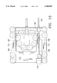
FIG. 2 is a bottom view of the automated crawling system of the present invention;
FIG. 3 is a cross sectional side view of the automated crawling system of the present invention;
FIG. 4 is a bottom view of the first leg of the automated crawling system at its front-most extreme position and the second leg at its rear-most extreme position;
FIG. 5 is a bottom view of the first leg of the automated crawling system at its rear-most extreme position and the second leg at its front-most extreme position;
FIGS. 6-12 illustrate sequential movement of the automated crawling system from point A to point B;
FIG. 13 is an alternative embodiment of the present invention; and
FIGS. 14-15 illustrate sequential movement of the automated crawling system of FIG. 13.
DETAILED DESCRIPTION OF THE PREFERRED EMBODIMENT
In the following description of the preferred embodiment, reference is made to the accompanying drawings which form a part hereof, and in which is shown by way of illustration a specific embodiment in which the invention may be practiced. It is to be understood that other embodiments may be utilized and structural changes may be made without departing from the scope of the present invention.
FIG. 1 is a perspective view of the automated crawling system of the present invention. FIG. 2 is a bottom view of the automated crawling system of the present invention.
Structural Components
The present invention is an automated crawling system 10 including a platform 12, such as a flat platform, a first leg assembly 14, a second leg assembly 16, a rail assembly 18, and an onboard electronic computer controller 21. The carrying area 19 can carry observation cameras, sensors and sensor manipulation devices, and data gathering equipment such as computer processors, and can transport hazardous materials, and can retrieve items and objects. The onboard computer controller 21 can control the movement of the robot with preprogrammed instructions or can accept remote commands.
The rail assembly 18 comprises a first rail 20, a second rail 22, and rail supports 24 located at an end 26, 28 of each rail 20, 22, respectively. The first and second rails 20, 22 are attached or mounted to the platform 12 and extend along opposite longsides 30, 32 of the platform 12 of the crawler 10.
The first leg assembly 14 comprises a mounting disc 34, such as a circular flat disc, a first bracket 36, and an intermittent coupling device 38, such as a plurality of vacuum cups 40. The intermittent coupling device 38 can comprise any mechanism suitable for intermittent coupling to a particular object (described in detail in the Operation section below). For example, an intermittent coupling device with a vacuum cup arrangement 40, as shown in FIG. 1, is suitable for intermittent coupling to a surface of a particular object and will be described hereafter as a working example. However, for ferromagnetic objects or objects with ferromagnetic surfaces, a magnetic device having intermittent activated solenoids can be utilized as the intermittent coupling device.
The mounting disc 34 is attached to the first bracket 36. The first bracket 36 preferably has two strips 46, 48 extending outwardly from the platform 12. A plurality of sliders 50 are preferably attached to each outside portion of the strips 46, 48 of the first bracket 36. Each slider 50 is also slidably coupled to one of the rails 20, 22 of the rail assembly 18. The sliders 50 provide the first bracket 36 with freedom of linear movement relative to the platform 12.
The second leg assembly 16 comprises a second bracket 52 and an intermittent coupling device 54 similar to the intermittent coupling device 38 of FIG. 1, which is preferably a plurality of vacuum cups 76 (similar to vacuum cups 40 of FIG. 2). The second bracket 52 is preferably a "U" shaped bracket with a topside surface and opposite inside surfaces. The second bracket 52 has a plurality of sliders 56 (similar to sliders 50 of FIG. 2) preferably attached to each inside surface of the second bracket 52. Each slider 56 is also slidably coupled to one of the rails 20, 22 of the rail assembly 18.
A first motor 58, which can be a conventional electric motor, is rigidly attached to the platform 12. The first motor 58 has a ball screw shaft 62 coupled to a first receiver 64 which can be attached to or integral with the first bracket 36. Also, the first motor 58 can have encoders (not shown) to determine the position of traversal of the first bracket 36. Since the first bracket 36 is slidably coupled to the platform 12 and the first receiver 64 is rigidly attached the first bracket 36, the first motor 58 and the ball screw shaft 62 provide the first bracket 36 with linear motion, relative to the platform 12, in either a forward or reverse direction (described in detail in the Operation section below).
Similar to the first motor 58 configuration, a second motor 66 is rigidly attached to the platform 12. The second motor 66 has a ball screw shaft 67 coupled to a second receiver 68 which can be attached to or integral with the second bracket 52. Also, the second motor 66 can have encoders (not shown) to determine the position of traversal of the second bracket 52. Since the second bracket 52 is slidably coupled to the platform 12 and the second receiver 68 is rigidly attached the second bracket 52, the second motor 66 and the ball screw shaft 67 provide the second bracket 52 with linear motion, relative to the platform 12, in either a forward or reverse direction (described in detail in the Operation section below).
FIG. 3 is a cross sectional side view of the automated crawling system of the present invention of FIG. 2. A rotary motor 70, which can be an ultrasonic motor, such as a low mass compact ultrasonic motor, or other type of rotary motor, is preferably attached to the first bracket 36 and is coupled to the mounting disc 34 via a shaft 71. The rotary motor 70 provides the mounting disc 34 with rotary motion in either a clockwise or counter clockwise direction.
Referring to FIG. 3 along with FIGS. 1 and 2, the vacuum cups 40 of the first leg assembly 14 are preferably attached to the mounting disc 34 so that they protrude from the mounting disc 34 as shown in FIG. 3. Each vacuum cup 40 has a separate vacuum pump 72 and a separate air cylinder 74 coupled to it and attached to the mounting disc 34. Each vacuum pump 72 provides such vacuum cup with a vacuum source independent of the other vacuum cups; such as a venturi vacuum pump.
The vacuum pumps 72 and the air cylinders 74 are also coupled to a standard air compressor (not shown) for providing each vacuum pump 72 and air cylinder 74 with air pressures preferably ranging from 70-120 psi. Flexible tubing 75, such as polyethylene tubing, PVC tubing, or the like, provides a means for transferring the air pressure from the air compressor to each vacuum pump 72 and each air cylinder 74.
The vacuum cups 76 of the second leg assembly 16 are preferably attached to the second bracket 52 so that they protrude from the topside surface of the second bracket 54. Similar to the vacuum cups 40 of the first leg assembly 14, each vacuum cup 76 of the second leg assembly 16 has a separate vacuum pump 84 coupled to it and attached to the second bracket 52. Also, each vacuum cup 76 of the second leg assembly 16 has a separate air cylinder 86 coupled to it and mounted behind each vacuum cup 76.
In addition, similar to the vacuum pumps 72 of the first leg assembly 14, each vacuum pump 84 of the second assembly 16 is preferably a venturi vacuum pump. Moreover, the air cylinders 86 and the vacuum pumps 84 of the second assembly 16 are coupled to the same air compressor (not shown) as the vacuum pumps 52 and air cylinders 54 of the first leg assembly 14. Flexible tubing 88 similar to flexible tubing 75 is used with the second leg assembly 16. As stated above, it should be noted that the intermittent coupling devices 38, 54 can be any device suitable for coupling to an object is not limited to being a vacuum pump device.
FIG. 4 is a bottom view of the first leg assembly and the second leg assembly of the automated crawling system of the present invention at their front-most extreme positions, respectively. FIG. 5 is a bottom view of the first leg assembly and the second leg assembly of the automated crawling system of the present invention at their rear-most extreme positions, respectively.
In addition, the rotary motor 70 allows movement of the first leg assembly 14 rotationally along the shaft 71, in the direction indicated by arrow 94 as shown in FIG. 3. A detailed description of the operation and the interaction of the components of the crawler 10 will be discussed in the Operation section below.
Operation
FIGS. 6-12 illustrate sequential movement of the automated crawling system from point A to point B to point C along x and y axes and around a z axis. The onboard computer controller 21 can control the movement of the robot with preprogrammed instructions or can accept remote commands. The crawler of the present invention effectuates movement with repetitive cyclic actions.
FIGS. 6-9 illustrate one cycle of linear movement and FIGS. 10-12 illustrate rotational movement. For each cycle, first referring to FIG. 6, the intermittent coupling device 54 of the second leg assembly 16 is initially coupled (as indicated by shading of the intermittent coupling device 54 of FIG. 6) to a particular object 100. During this, the intermittent coupling device 38 of the first leg assembly 14 remains uncoupled (as indicated by non-shading of the intermittent coupling device 38 of FIG. 6) to the object 100.
Next, as shown in FIG. 7, the second leg assembly 16 is linearly traversed by the second motor 66. Linear movement of the platform 12 relative to the object 100, as indicated by arrow 102, is accomplished by operating the second motor 66. As the second motor 66 operates, the ball screw shaft 67 traverses along the second receiver 68. After traversal, the second leg assembly 16 is uncoupled from the object 100.
Third, as shown in FIG. 8, the intermittent coupling device 38 of the first leg assembly 14 is coupled (as indicated by shading of the intermittent coupling device 38 of FIG. 7) to the object 100 while the intermittent coupling device 54 of the second leg assembly 16 remains uncoupled (as indicated by non-shading of the intermittent coupling device 54 of FIG. 7) to the object 100. It should be noted that while the previous step is being completed, the crawler 10 prepares a subsequent step for movement by operating the first motor 58. One of the leg assemblies 14 or 16, move relative to the object 100.
Fourth, as shown in FIG. 9 and similar to the movement of the second leg assembly 16, linear movement of the platform 12 relative to the object 100, as indicated by arrow 104, is accomplished by operating the first motor 58. As the first motor 58 operates, the ball screw shaft 62 traverses along the first receiver 64. Since the first receiver 64 is rigidly attached to the second bracket 52, the first motor 58 is rigidly attached to the platform 12, and the platform 12 is slidably attached to the second bracket 52 via the rails 20, 22, linear movement (forward or reverse) of the second bracket 52 along the rails 20, 22 relative to the platform 12 is accomplished.
Further, as shown in FIG. 10, the crawler of the present invention can rotationally change direction of movement with a 360 degree range of motion. For example, first the intermittent coupling device 38 of the first leg assembly 14 is coupled (indicated by shading of the intermittent coupling device 38 of FIG. 10) to the object 100. Next, the intermittent coupling device 54 of the second leg assembly 16 is uncoupled (indicated by non-shading of the intermittent coupling device 54 of FIG. 7) to the object 100.
The rotary motor 70 is then operated for providing the mounting disc 34 with rotary motion in either a clockwise, as indicated by arrow 106 to reach point C, or counter clockwise direction. Since the rotary motor 70 provides relative rotational motion between the mounting disc 34 and the first bracket 36, and the first bracket 36 is attached to the platform 12, the platform 12 rotates during operation of the rotary motor 70, with a range of motion of 360 degrees.
After the desired rotation of the crawler is achieved, the crawler can be linearly traversed by repeating cycles of movement as discussed above. As shown in FIG. 11, the intermittent coupling device 54 of the second leg assembly 16 is again coupled (as indicated by shading of the intermittent coupling device 54 of FIG. 11) to the object 100. During this, the intermittent coupling device 38 of the first leg assembly 14 is uncoupled (as indicated by non-shading of the intermittent coupling device 38 of FIG. 11) to the object 100. Next, as shown in FIG. 12, the second leg assembly 16 is linearly traversed, as indicated by arrow 108, by the second motor 66 in accordance with the above discussion.
FIG. 13 is an alternative embodiment of the present invention. Alternatively, a more compact crawler is disclosed with a second leg assembly 110 having a compact bracket 112 slidably coupled to a platform 114. The crawler also includes a motor 116. The second leg assembly has a second ball screw 118 and a second receiver 120 operated by the motor 116 and physically located on one side of the platform 114. The crawler further includes a first leg assembly 122 having a compact bracket 124 slidably coupled to the platform 114 and a first ball screw 126 and a first receiver 128 operated by the motor 116 and physically located opposite the second ball screw 118. The first ball screw 126 of the first leg assembly 122 has an opposite pitch from the second ball screw 118 (i.e., right versus left hand threads) and is attached to the second ball screw 118 so that the motor 116 drives both ball screws 118, 126.
Linear movement of the platform 114 of FIG. 13 via the leg assemblies 110, 124 is similar to the linear movement of the platform 12 of FIGS. 6-12 with the exception of using only one motor for linear motion. Specifically, the one motor 116 turns both the first ball screw 126 and the second ball screw 118. Thus, the crawler is more compact and has fewer motors.
For instance, as shown in FIG. 14, the first leg assembly 14 is coupled (as indicated by shading of the first leg assembly 122 of FIG. 14) to an object 130 while the second leg assembly 110 remains uncoupled (as indicated by non-shading of the second leg assembly 110 of FIG. 14) to the object 130. Next, as shown in FIG. 15, linear movement of the crawler as indicated by arrow 132, is accomplished by operating the motor 116.
The foregoing description of the preferred embodiment of the invention has been presented for the purposes of illustration and description. It is not intended to be exhaustive or to limit the invention to the precise form disclosed. Many modifications and variations are possible in light of the above teaching. It is intended that the scope of the invention be limited not by this detailed description, but rather by the claims appended hereto.

Claims (11)

What is claimed is:
1. An automated crawling robot system for traversing about an object with a range of motion of 360 degrees, comprising:
a platform;
a first leg assembly slidably coupled to the platform and rotatably coupled to the platform and having an intermittent coupling device for intermittently coupling the first leg assembly to the object and a first ball screw and receiver system;
a second leg assembly slidably coupled to the platform and having an intermittent coupling device for intermittently coupling the second leg assembly to the object and a second ball screw and receiver system;
a motor for driving the first and second ball screw and receiver systems;
wherein said first ball screw is located opposite the second ball screw, has an opposite pitch from the second ball screw, and is attached to the second ball screw so that the motor can drive both ball screws; and
a rotary motor for rotatably traversing the second leg assembly relative to the platform.
2. The invention as set forth in claim 1, further comprising an onboard computer controller for controlling the movement of the robot with preprogrammed instructions and with remote commands.
3. The invention as set forth in claim 1, further comprising a carrying area for carrying data gathering equipment and for transporting materials.
4. The invention as set forth in claim 1, wherein said platform further comprises a rail system, wherein said first and second leg assemblies slidably traverse about said rail system.
5. The invention as set forth in claim 1, wherein said rotary motor is a low mass compact ultrasonic motor.
6. The invention as set forth in claim 1, wherein said intermittent coupling device is a magnetic device having intermittently activated solenoids.
7. The invention as set forth in claim 1, wherein said intermittent coupling device is a plurality of suction cups.
8. The invention as set forth in claim 7, wherein said plurality of suction cups are a plurality of vacuum cups, each having a separate vacuum pump and a separate air cylinder coupled to it, wherein each vacuum pump provides each vacuum cup with a vacuum source independent of the other vacuum cups.
9. The invention as set forth in claim 8, wherein said vacuum pumps are venturi vacuum pumps.
10. The invention as set forth in claim 8, wherein said vacuum pumps and said air cylinders are coupled to a standard air compressor for providing each vacuum pump and each air cylinder with air pressures.
11. The invention as set forth in claim 10, further comprising flexible tubing for providing a means for transferring the air pressure from the air compressor to each vacuum pump and each air cylinder.
US09/220,493 1996-08-01 1998-12-22 Multifunction automated crawling system Expired - Lifetime US6105695A (en)

Priority Applications (1)

Application Number Priority Date Filing Date Title
US09/220,493 US6105695A (en) 1996-08-01 1998-12-22 Multifunction automated crawling system

Applications Claiming Priority (2)

Application Number Priority Date Filing Date Title
US08/691,202 US5890553A (en) 1996-08-01 1996-08-01 Multifunction automated crawling system
US09/220,493 US6105695A (en) 1996-08-01 1998-12-22 Multifunction automated crawling system

Related Parent Applications (1)

Application Number Title Priority Date Filing Date
US08/691,202 Division US5890553A (en) 1996-08-01 1996-08-01 Multifunction automated crawling system

Publications (1)

Publication Number Publication Date
US6105695A true US6105695A (en) 2000-08-22

Family

ID=24775562

Family Applications (2)

Application Number Title Priority Date Filing Date
US08/691,202 Expired - Lifetime US5890553A (en) 1996-08-01 1996-08-01 Multifunction automated crawling system
US09/220,493 Expired - Lifetime US6105695A (en) 1996-08-01 1998-12-22 Multifunction automated crawling system

Family Applications Before (1)

Application Number Title Priority Date Filing Date
US08/691,202 Expired - Lifetime US5890553A (en) 1996-08-01 1996-08-01 Multifunction automated crawling system

Country Status (1)

Country Link
US (2) US5890553A (en)

Cited By (28)

* Cited by examiner, † Cited by third party
Publication number Priority date Publication date Assignee Title
US6512345B2 (en) 2001-03-30 2003-01-28 The Regents Of The University Of Michigan Apparatus for obstacle traversion
US20030048081A1 (en) * 2001-09-09 2003-03-13 Advanced Robotic Vehicles, Inc. Surface adhering tool carrying robot
US20040073411A1 (en) * 2002-10-15 2004-04-15 The Boeing Company System, method and computer program product for maintaining a structure
US20040131462A1 (en) * 2002-07-22 2004-07-08 Hawkins Phillip J. Miniature manipulator for servicing the interior of nuclear steam generator tubes
US20040140786A1 (en) * 2001-03-30 2004-07-22 Johann Borenstein Apparatus for obstacle traversion
WO2004098984A1 (en) * 2003-05-07 2004-11-18 Unique Cleaning Systems Gmbh Automatic climbing mechanism for facades, especially glass facades
US20040247396A1 (en) * 2001-05-09 2004-12-09 Kazuo Okutsu Gallery monitoring method and monitorting system
US20040251920A1 (en) * 2003-06-11 2004-12-16 Engelbart Roger W. Apparatus and methods for non-destructive inspection using microwave sensing
US20050007055A1 (en) * 2001-03-30 2005-01-13 Johann Borenstein Integrated, proportionally controlled, and naturally compliant universal joint actuator with controllable stiffness
US20050072612A1 (en) * 2003-10-07 2005-04-07 Maggio Samuel J. Surface traversing apparatus and method
US6907799B2 (en) * 2001-11-13 2005-06-21 Bae Systems Advanced Technologies, Inc. Apparatus and method for non-destructive inspection of large structures
US7156189B1 (en) 2004-12-01 2007-01-02 The United States Of America As Represented By The Administrator Of The National Aeronautics And Space Administration Self mountable and extractable ultrasonic/sonic anchor
US20070193757A1 (en) * 2006-02-03 2007-08-23 California Institute Of Technology Ultrasonic/sonic jackhammer
US7266421B1 (en) * 1998-11-10 2007-09-04 Commissariat A L'energie Atomique System for controlling lifting and remote handling units located in a confined enclosure
EP1884453A2 (en) 2006-07-31 2008-02-06 Airbus Espaa, S.L. Crawler robot equipped with a work unit, and control system for such crawler robots
US20090188730A1 (en) * 2005-07-08 2009-07-30 Limbacher Jr H Phillip Ambulatory vehicle
US7604075B1 (en) 2005-07-08 2009-10-20 Limbacher Jr H Phillip Ambulatory vehicle
DE102009047992B3 (en) * 2009-10-01 2011-03-17 Niederberger Patent Ag Climbing robot for driving on adhesive surfaces
DE102009047991B3 (en) * 2009-10-01 2011-03-31 Niederberger Patent Ag Climbing robot for driving on adhesive surfaces
US8159357B1 (en) 2009-03-30 2012-04-17 Philip Onni Jarvinen Means to prospect for water ice on heavenly bodies
US20130061696A1 (en) * 2011-09-12 2013-03-14 Honeywell International Inc. System for the automated inspection of structures at height
CZ303697B6 (en) * 2011-07-19 2013-03-20 Technická univerzita v Liberci Mobile platform for movement on vertical wall
US20140033837A1 (en) * 2009-01-19 2014-02-06 Babcock & Wilcox Nuclear Energy, Inc. Apparatus for Automated Positioning of Eddy Current Test Probe
US20160052573A1 (en) * 2014-08-20 2016-02-25 Carl Flynt Higginbotham, III Load transporting apparatus and methods of using same
CN107157411A (en) * 2017-07-12 2017-09-15 烟台海特林自动化科技有限公司 Adsorb the cleaning robot of climbing mechanism and absorption glass curtain wall
US20180154960A1 (en) * 2015-12-04 2018-06-07 James Walter Beard, III Climbing Vehicle using Suction with Variable Adaptive Suspension Seal
US10919589B1 (en) 2020-04-21 2021-02-16 International Climbing Machines, Inc. Hybrid surface-traversing apparatus and method
US11021259B1 (en) 2021-01-07 2021-06-01 Philip Onni Jarvinen Aircraft exhaust mitigation system and process

Families Citing this family (37)

* Cited by examiner, † Cited by third party
Publication number Priority date Publication date Assignee Title
FR2742209B1 (en) * 1995-12-08 1998-02-20 Leteurtre Patrick SINGLE-AXIS OR THREE-AXIS POSITIONING JACKS AND SERVO-BASED METHODS USING THE SAME
KR20010001976A (en) * 1999-06-10 2001-01-05 김형벽 Multifunctional robot hand
US6793026B1 (en) * 2000-08-22 2004-09-21 I Robot Corporation Wall-climbing robot
WO2005089346A2 (en) * 2004-03-15 2005-09-29 The University Of Vermont And State Agricultural College Systems comprising a mechanically actuated magnetic on-off attachment device
ES2279693B1 (en) * 2005-07-20 2008-05-16 M.Torres Diseños Industriales, S.A.U. FLEXIBLE ASSEMBLY FOR WORK ON LARGE SURFACES.
WO2007103914A2 (en) * 2006-03-06 2007-09-13 Brooks Ronald J Process and apparatus for soft tissue manipulation
US7784570B2 (en) 2006-10-06 2010-08-31 Irobot Corporation Robotic vehicle
US8413752B2 (en) * 2006-10-06 2013-04-09 Irobot Corporation Robotic vehicle
US7654348B2 (en) 2006-10-06 2010-02-02 Irobot Corporation Maneuvering robotic vehicles having a positionable sensor head
AU2007347733B2 (en) 2006-10-06 2012-05-03 Irobot Corporation Robotic vehicle
US7891446B2 (en) * 2006-10-06 2011-02-22 Irobot Corporation Robotic vehicle deck adjustment
US8644991B2 (en) 2006-10-06 2014-02-04 Irobot Corporation Maneuvering robotic vehicles
US20090095096A1 (en) * 2007-10-10 2009-04-16 Charles Edwin Dean Hazardous materials sensing robot
WO2009144627A1 (en) * 2008-05-30 2009-12-03 Koninklijke Philips Electronics N.V. Moving system and method of moving a platform
WO2010142044A1 (en) * 2009-06-10 2010-12-16 Robotinc.Ch Ag Wall climbing apparatus
JP2012224326A (en) * 2011-04-04 2012-11-15 Kenji Hayashi Wall climbing robot
US8738226B2 (en) * 2011-07-18 2014-05-27 The Boeing Company Holonomic motion vehicle for travel on non-level surfaces
NZ595509A (en) * 2011-09-30 2014-06-27 Xiaoqi Chen Robotic climbing platform
ITPD20120258A1 (en) * 2012-09-07 2014-03-08 Nello Nalesso MOVEMENT SYSTEM FOR ROBOTS THAT MOVES ON SURFACES EVEN IN THE PRESENCE OF OBSTACLES
US10065280B2 (en) 2012-10-30 2018-09-04 The Boeing Company Multifunction legs for autonomous crawling assembly equipment
US9475527B2 (en) * 2012-10-30 2016-10-25 The Boeing Company Autonomous crawling assembly system
US9327376B2 (en) 2012-10-30 2016-05-03 The Boeing Company Dual function movement component for automated assembly systems
US10001245B2 (en) 2014-12-08 2018-06-19 The Boeing Company Apparatus and method for coupling an end effector to a structure
CN104670356A (en) * 2015-02-10 2015-06-03 徐州工业职业技术学院 Guide post type sucking disc wall-climbing robot
CH711196A2 (en) * 2015-06-05 2016-12-15 Logistics Wash Holding Ag Chassis with linear and pivoting movements with detachable feet detachable with respect to the travel surface.
EP4219096A1 (en) 2015-08-26 2023-08-02 Berkshire Grey Operating Company, Inc. Systems and methods for providing vacuum valve assemblies for end effectors
CN105416429B (en) * 2015-12-10 2019-05-14 华南理工大学 A kind of climbing robot walking mechanism
TWI581844B (en) * 2016-01-27 2017-05-11 Genius Toy Taiwan Co Ltd Climbing wall toys
CN106080824A (en) * 2016-06-30 2016-11-09 山东聚天工工业自动化有限公司 Pan Bi robot and robot movement control method and robot obstacle-overpass control method
US10226944B2 (en) 2016-08-30 2019-03-12 The Boeing Company Adaptable surface treatment repair system
CN107364503A (en) * 2017-07-17 2017-11-21 上海伟匠机器人科技有限公司 Climb wall device and its method of creeping, sweeping robot, spray robot
US11548634B2 (en) * 2017-10-28 2023-01-10 Avestec Technologies Inc. Method and apparatus for surface attachment of modular unmanned aerial vehicle for inspection
FR3083469B1 (en) * 2018-07-09 2020-10-16 Inst De Rech Tech Jules Verne WELDING ROBOT
CN109178131A (en) * 2018-09-18 2019-01-11 罗洋 Multilayer leg formula climbing robot and climb wall loading system
AU2018446093A1 (en) * 2018-10-16 2021-05-20 Michael Traut Lifting device for the translational progressive movement of a motor vehicle
CN110104084B (en) * 2019-05-21 2021-04-20 上海海洋大学 Wall-climbing robot with mechanical pneumatic sucker
CA3150291A1 (en) 2019-08-08 2021-02-11 Berkshire Grey, Inc. Systems and methods for providing, in programmable motion devices, compliant end effectors with noise mitigation

Citations (8)

* Cited by examiner, † Cited by third party
Publication number Priority date Publication date Assignee Title
US4321976A (en) * 1979-02-15 1982-03-30 Fried. Krupp Gesellschaft Mit Beschrankter Haftung Machine stepper
US4674949A (en) * 1982-01-11 1987-06-23 International Robotic Engineering, Inc. Robot with climbing feet
US4790400A (en) * 1986-07-24 1988-12-13 Eric Sheeter Stepping vehicle
US4940382A (en) * 1987-12-31 1990-07-10 Aerospatiale Societe Nationale Industrielle Autonomous moving body for transporting a tool at a constant speed
US5161631A (en) * 1989-11-27 1992-11-10 Uragami Fukashi Suction device capable of moving along a surface
US5351773A (en) * 1992-12-01 1994-10-04 Ken Yanagisawa Walking robot
US5429009A (en) * 1993-05-20 1995-07-04 Carnegie Mellon University Robot with cruciform geometry
US5839532A (en) * 1995-03-22 1998-11-24 Honda Giken Kogyo Kabushiki Kaisha Vacuum wall walking apparatus

Family Cites Families (9)

* Cited by examiner, † Cited by third party
Publication number Priority date Publication date Assignee Title
US2230759A (en) * 1936-06-08 1941-02-04 Page Engineering Company Self-propelled apparatus
US2660253A (en) * 1951-12-31 1953-11-24 Bucyrus Eric Company Supporting propulsion means for draglines and the like
SU397612A1 (en) * 1972-04-24 1973-09-17 TRAVELING EQUIPMENT HEAVY DUTY CARS
US3913452A (en) * 1973-08-01 1975-10-21 Combustion Eng Remotely movable platform
JPS6167679A (en) * 1984-09-11 1986-04-07 Toshiba Corp Shifter on magnetic body
US5040626A (en) * 1986-02-12 1991-08-20 Nathaniel A. Hardin Walking robots having double acting fluid driven twistor pairs as combined joints and motors and method of locomotion
KR900008369Y1 (en) * 1987-11-24 1990-09-15 박흥종 Automatic direction changing apparatus for vehicle
JPH05131382A (en) * 1991-11-11 1993-05-28 Takeshi Yanagisawa Walking robot
US5551525A (en) * 1994-08-19 1996-09-03 Vanderbilt University Climber robot

Patent Citations (8)

* Cited by examiner, † Cited by third party
Publication number Priority date Publication date Assignee Title
US4321976A (en) * 1979-02-15 1982-03-30 Fried. Krupp Gesellschaft Mit Beschrankter Haftung Machine stepper
US4674949A (en) * 1982-01-11 1987-06-23 International Robotic Engineering, Inc. Robot with climbing feet
US4790400A (en) * 1986-07-24 1988-12-13 Eric Sheeter Stepping vehicle
US4940382A (en) * 1987-12-31 1990-07-10 Aerospatiale Societe Nationale Industrielle Autonomous moving body for transporting a tool at a constant speed
US5161631A (en) * 1989-11-27 1992-11-10 Uragami Fukashi Suction device capable of moving along a surface
US5351773A (en) * 1992-12-01 1994-10-04 Ken Yanagisawa Walking robot
US5429009A (en) * 1993-05-20 1995-07-04 Carnegie Mellon University Robot with cruciform geometry
US5839532A (en) * 1995-03-22 1998-11-24 Honda Giken Kogyo Kabushiki Kaisha Vacuum wall walking apparatus

Cited By (55)

* Cited by examiner, † Cited by third party
Publication number Priority date Publication date Assignee Title
US7266421B1 (en) * 1998-11-10 2007-09-04 Commissariat A L'energie Atomique System for controlling lifting and remote handling units located in a confined enclosure
US20050007055A1 (en) * 2001-03-30 2005-01-13 Johann Borenstein Integrated, proportionally controlled, and naturally compliant universal joint actuator with controllable stiffness
US6870343B2 (en) 2001-03-30 2005-03-22 The University Of Michigan Integrated, proportionally controlled, and naturally compliant universal joint actuator with controllable stiffness
US20040140786A1 (en) * 2001-03-30 2004-07-22 Johann Borenstein Apparatus for obstacle traversion
US6774597B1 (en) 2001-03-30 2004-08-10 The Regents Of The University Of Michigan Apparatus for obstacle traversion
US6512345B2 (en) 2001-03-30 2003-01-28 The Regents Of The University Of Michigan Apparatus for obstacle traversion
US7287934B2 (en) * 2001-05-09 2007-10-30 Kajima Corporation Stratum disposal monitoring system
US20040247396A1 (en) * 2001-05-09 2004-12-09 Kazuo Okutsu Gallery monitoring method and monitorting system
US20050113975A1 (en) * 2001-09-09 2005-05-26 Advanced Robotic Vehicles, Inc. Method for inspection of objects using surface adhering robot
US7155307B2 (en) 2001-09-09 2006-12-26 Seemann Henry R Surface adhering tool carrying robot
US20050119789A1 (en) * 2001-09-09 2005-06-02 Advanced Robotic Vehicles, Inc. Method for fabricating sliding vacuum cups
US7280890B2 (en) 2001-09-09 2007-10-09 Advanced Robotics Vehicles, Inc. Method for fabricating sliding vacuum cups
US20030048081A1 (en) * 2001-09-09 2003-03-13 Advanced Robotic Vehicles, Inc. Surface adhering tool carrying robot
US7076335B2 (en) 2001-09-09 2006-07-11 Advanced Robotic Vehicles, Inc. Method for inspection of objects using surface adhering robot
US6907799B2 (en) * 2001-11-13 2005-06-21 Bae Systems Advanced Technologies, Inc. Apparatus and method for non-destructive inspection of large structures
US7314343B2 (en) * 2002-07-22 2008-01-01 Westinghouse Electric Co. Llc Miniature manipulator for servicing the interior of nuclear steam generator tubes
US20040131462A1 (en) * 2002-07-22 2004-07-08 Hawkins Phillip J. Miniature manipulator for servicing the interior of nuclear steam generator tubes
US20040073411A1 (en) * 2002-10-15 2004-04-15 The Boeing Company System, method and computer program product for maintaining a structure
KR100804308B1 (en) 2003-05-07 2008-02-18 유닉 클리닝 시스템스 게엠베하 Automatic climbing mechanism for facades, especially glass facades
WO2004098984A1 (en) * 2003-05-07 2004-11-18 Unique Cleaning Systems Gmbh Automatic climbing mechanism for facades, especially glass facades
US6940295B2 (en) * 2003-06-11 2005-09-06 The Boeing Company Apparatus and methods for non-destructive inspection using microwave sensing
US20040251920A1 (en) * 2003-06-11 2004-12-16 Engelbart Roger W. Apparatus and methods for non-destructive inspection using microwave sensing
US6964312B2 (en) 2003-10-07 2005-11-15 International Climbing Machines, Inc. Surface traversing apparatus and method
US20060278454A1 (en) * 2003-10-07 2006-12-14 International Climbing Machines Surface traversing apparatus and method
US20050072612A1 (en) * 2003-10-07 2005-04-07 Maggio Samuel J. Surface traversing apparatus and method
US7775312B2 (en) 2003-10-07 2010-08-17 International Climbing Machines, Inc. Surface traversing apparatus and method
US7156189B1 (en) 2004-12-01 2007-01-02 The United States Of America As Represented By The Administrator Of The National Aeronautics And Space Administration Self mountable and extractable ultrasonic/sonic anchor
US7878276B2 (en) 2005-07-08 2011-02-01 H. Phillip Limbacher, Jr. Ambulatory vehicle
US20090188730A1 (en) * 2005-07-08 2009-07-30 Limbacher Jr H Phillip Ambulatory vehicle
US7604075B1 (en) 2005-07-08 2009-10-20 Limbacher Jr H Phillip Ambulatory vehicle
US8910727B2 (en) 2006-02-03 2014-12-16 California Institute Of Technology Ultrasonic/sonic jackhammer
US20070193757A1 (en) * 2006-02-03 2007-08-23 California Institute Of Technology Ultrasonic/sonic jackhammer
US20080077276A1 (en) * 2006-07-31 2008-03-27 Pedro Montero Sanjuan Crawler robot equipped with a work unit, and governing equipment for such crawler robots
EP1884453A3 (en) * 2006-07-31 2010-12-22 Airbus Operations S.L. Crawler robot equipped with a work unit, and control system for such crawler robots
EP1884453A2 (en) 2006-07-31 2008-02-06 Airbus Espaa, S.L. Crawler robot equipped with a work unit, and control system for such crawler robots
US8019472B2 (en) * 2006-07-31 2011-09-13 Airbus Operations, S.L. Crawler robot equipped with a work unit, and governing equipment for such crawler robots
US9273985B2 (en) * 2009-01-19 2016-03-01 Bwxt Nuclear Energy, Inc. Apparatus for automated positioning of eddy current test probe
US20140033837A1 (en) * 2009-01-19 2014-02-06 Babcock & Wilcox Nuclear Energy, Inc. Apparatus for Automated Positioning of Eddy Current Test Probe
US8159357B1 (en) 2009-03-30 2012-04-17 Philip Onni Jarvinen Means to prospect for water ice on heavenly bodies
DE102009047992B3 (en) * 2009-10-01 2011-03-17 Niederberger Patent Ag Climbing robot for driving on adhesive surfaces
WO2011038870A1 (en) 2009-10-01 2011-04-07 Niederberger Patent Ag Climbing robot for travelling over adhesive surfaces
DE102009047991B3 (en) * 2009-10-01 2011-03-31 Niederberger Patent Ag Climbing robot for driving on adhesive surfaces
WO2011038871A1 (en) 2009-10-01 2011-04-07 Niederberger Patent Ag Climbing robot for travelling over adhesive surfaces
CZ303697B6 (en) * 2011-07-19 2013-03-20 Technická univerzita v Liberci Mobile platform for movement on vertical wall
US20130061696A1 (en) * 2011-09-12 2013-03-14 Honeywell International Inc. System for the automated inspection of structures at height
US8640558B2 (en) * 2011-09-12 2014-02-04 Honeywell International Inc. System for the automated inspection of structures at height
US20160052573A1 (en) * 2014-08-20 2016-02-25 Carl Flynt Higginbotham, III Load transporting apparatus and methods of using same
US10988191B2 (en) * 2014-08-20 2021-04-27 Hydraulic Systems, Llc Load transporting apparatus and methods of using same
US20180154960A1 (en) * 2015-12-04 2018-06-07 James Walter Beard, III Climbing Vehicle using Suction with Variable Adaptive Suspension Seal
US10518830B2 (en) * 2015-12-04 2019-12-31 James Walter Beard, III Climbing vehicle using suction with variable adaptive suspension seal
CN107157411A (en) * 2017-07-12 2017-09-15 烟台海特林自动化科技有限公司 Adsorb the cleaning robot of climbing mechanism and absorption glass curtain wall
US10919589B1 (en) 2020-04-21 2021-02-16 International Climbing Machines, Inc. Hybrid surface-traversing apparatus and method
WO2021216141A1 (en) 2020-04-21 2021-10-28 International Climbing Machines, Inc. Hybrid surface-traversing apparatus and method
US11597455B2 (en) 2020-04-21 2023-03-07 International Climbing Machines, Inc. Hybrid surface-traversing apparatus and method
US11021259B1 (en) 2021-01-07 2021-06-01 Philip Onni Jarvinen Aircraft exhaust mitigation system and process

Also Published As

Publication number Publication date
US5890553A (en) 1999-04-06

Similar Documents

Publication Publication Date Title
US6105695A (en) Multifunction automated crawling system
JP7232581B2 (en) Stabilization of the tool holding end of the extended reach arm of automated equipment
Todd Fundamentals of robot technology: An introduction to industrial robots, teleoperators and robot vehicles
KR101909766B1 (en) Holonomic motion vehicle for travel on non-level surfaces
Shen et al. Proposed wall climbing robot with permanent magnetic tracks for inspecting oil tanks
Lee et al. Series of Multilinked Caterpillar Track‐type Climbing Robots
Kwon et al. A flat pipeline inspection robot with two wheel chains
US10053165B2 (en) Automated maintenance of surface skins using transporter system
US5451134A (en) Material handling devices and controllers
Zhang et al. A series of pneumatic glass‐wall cleaning robots for high‐rise buildings
KR20180132964A (en) Spring type worm handler for robot devices
CN108326839B (en) Seven-degree-of-freedom robot
US9010684B2 (en) Automated inspection of soft-tooled hollow structure
CN104925159A (en) Reconnaissance type obstacle-surmounting machine snake
CN109792888B (en) Double-arm apple picking trapezoid grading collection robot and picking grading operation method thereof
CN108453697A (en) A kind of glass multidimensional mounting robot
Kang et al. ROBHAZ-DT2: Design and integration of passive double tracked mobile manipulator system for explosive ordnance disposal
CN109795879B (en) Posture adjusting butt joint device, system and method based on six-degree-of-freedom parallel mechanism
US20190381655A1 (en) Grounded SEA Actuator
CN107416062A (en) The climbing robot and its detection method of a kind of restructural
Miyake et al. Development of small-size window cleaning robot by wall climbing mechanism
US11124977B2 (en) System and method for constructing a brick structure with a cable-driven robot
EP3808510A1 (en) Tele-commanded robot
Bar-Cohen et al. Multifunction automated crawling system
KR102456979B1 (en) A pipe inspection robot and operating method of the same

Legal Events

Date Code Title Description
AS Assignment

Owner name: CALIFORNIA INSTITUTE OF TECHNOLOGY, CALIFORNIA

Free format text: ASSIGNMENT OF ASSIGNORS INTEREST;ASSIGNORS:BAR-COHEN, YOSEPH;JOFFE, BENJAMIN;BACKES, PAUL;REEL/FRAME:009675/0734

Effective date: 19960725

STCF Information on status: patent grant

Free format text: PATENTED CASE

AS Assignment

Owner name: NATIONAL AERONAUTICS AND SPACE ADMINISTRATION, DIS

Free format text: CONFIRMATORY LICENSE;ASSIGNOR:CALIFORNIA INSTITUTE OF TECHNOLOGY;REEL/FRAME:011469/0283

Effective date: 20001216

FPAY Fee payment

Year of fee payment: 4

FPAY Fee payment

Year of fee payment: 8

FPAY Fee payment

Year of fee payment: 12