US6101273A - Image reproducing method and apparatus - Google Patents
Image reproducing method and apparatus Download PDFInfo
- Publication number
- US6101273A US6101273A US08/741,722 US74172296A US6101273A US 6101273 A US6101273 A US 6101273A US 74172296 A US74172296 A US 74172296A US 6101273 A US6101273 A US 6101273A
- Authority
- US
- United States
- Prior art keywords
- dynamic range
- image signal
- image
- signal
- rate
- Prior art date
- Legal status (The legal status is an assumption and is not a legal conclusion. Google has not performed a legal analysis and makes no representation as to the accuracy of the status listed.)
- Expired - Lifetime
Links
Images


Classifications
-
- H—ELECTRICITY
- H04—ELECTRIC COMMUNICATION TECHNIQUE
- H04N—PICTORIAL COMMUNICATION, e.g. TELEVISION
- H04N1/00—Scanning, transmission or reproduction of documents or the like, e.g. facsimile transmission; Details thereof
- H04N1/40—Picture signal circuits
- H04N1/407—Control or modification of tonal gradation or of extreme levels, e.g. background level
- H04N1/4072—Control or modification of tonal gradation or of extreme levels, e.g. background level dependent on the contents of the original
- H04N1/4074—Control or modification of tonal gradation or of extreme levels, e.g. background level dependent on the contents of the original using histograms
Definitions
- This invention relates to an image reproducing method and apparatus for reproducing a visible image from an image signal, which is obtained from a color image carried on a reflection type of image storage sheet, such as a photograph or printed matter, or a transmission type of image storage sheet, such as negative film or reversal film.
- an image having been recorded on photographic film (hereinbelow referred to as the film), such as negative film or reversal film, or on printed matter is photoelectrically read out, and an image signal having thus been obtained is converted into a digital signal.
- the digital signal is then subjected to various kinds of image processing, and a processed image signal is thereby obtained.
- recording light is modulated with the processed image signal, and a photosensitive material, such as photographic paper, is scanned with and exposed to the modulated recording light. In this manner, a visible image is printed on the photosensitive material.
- the digital photo printers are constituted of a read-out means for reading out an image having been recorded on an image storage sheet, such as film, and an image reproducing means.
- the image reproducing means carries out image processing on the image signal having thus been detected by the read-out means, and adjusts exposure conditions.
- the image reproducing means carries out a scanning exposure operation on a photosensitive material under the adjusted exposure conditions and carries out development processing on the exposed photosensitive material.
- the image reproducing means can reproduce a visible image from the image signal having been obtained from the image processing and can display the visible image on a monitor.
- a read-out apparatus for reading out an image having been recorded on film, or the like wherein slit scanning is carried out
- reading light having a slit-like shape extending in a one-dimensional direction is irradiated to the film, and the film is moved in a direction, which is approximately normal to the one-dimensional direction.
- the reading light and a photoelectric converting device are moved in the direction, which is approximately normal to the one-dimensional direction.
- the film is scanned in two-dimensional directions.
- An image of the light, which has passed through the film and carries the film image information, is formed on a light receiving face of the photoelectric converting device, such as a CCD line sensor, and is thus photoelectrically converted into a light amount signal.
- the thus detected light amount signal is amplified and is then converted into a digital signal by an analog-to-digital converter. Thereafter, the digital signal is subjected to various kinds of image processing, such as compensation for a fluctuation in the characteristics among the CCD elements of the CCD line sensor, image density conversion, and conversion of magnification, and a processed signal obtained from the image processing is transferred to a reproducing means.
- image processing such as compensation for a fluctuation in the characteristics among the CCD elements of the CCD line sensor, image density conversion, and conversion of magnification, and a processed signal obtained from the image processing is transferred to a reproducing means.
- a visible image is reproduced from the received image signal and displayed on a display device, such as a cathode ray tube (CRT) display device.
- a display device such as a cathode ray tube (CRT) display device.
- the operator who views the reproduced image, corrects the gradation, the color, the image density, or the like, of the reproduced image (i.e., sets the set-up conditions).
- the image signal is transferred as the recording image information into a development means or a monitor.
- an image reproducing apparatus in which the image reproduction with raster scanning (i.e., light beam scanning) is utilized, three kinds of light beams corresponding to exposure of the layers, which are formed on a photosensitive material and are sensitive to three primary colors, e.g. red (R), green (G), and blue (B), are modulated in accordance with the recording image information and deflected in a main scanning direction (which corresponds to the aforesaid one-dimensional direction). Also, the photosensitive material is conveyed in a sub-scanning direction, which is approximately normal to the main scanning direction.
- raster scanning i.e., light beam scanning
- the photosensitive material is thus moved with respect to the deflected light beams and in the sub-scanning direction.
- the photosensitive material is scanned in two-dimensional directions with the light beams, which have been modulated in accordance with the recording image information, and the image having been read out from the film is thereby reproduced on the photosensitive material.
- the photosensitive material having thus been scanned with and exposed to the light beams is then subjected to development processing in accordance with the kind of the photosensitive material.
- development processing comprising the steps of color development, bleach-fix, washing, drying, and the like. A finished print is thereby obtained.
- Such a photosensitive material can record a comparatively wide range of luminance of the object.
- the maximum image density on the photosensitive material is limited. Therefore, in cases where a print of a scene having a large difference in luminance is obtained with an ordinary printing technique, details become imperceptible due to insufficient gradation in either one of a bright portion (a highlight) and a dark portion (a shadow) on the print. For example, in cases where a picture of a person is taken against the light, if the picture is printed such that the image of the person may become clear, the bright portion, such as the sky region, will become white and its details will become imperceptible.
- an ordinary level of exposure is given to a region having an intermediate level of image density in a scene.
- a long time of exposure is given selectively to a region, which is considered to become white and the details of which are considered to become imperceptible on the print, by using a perforated blocking sheet.
- the exposure time is kept short selectively by using a blocking sheet. In this manner, the print is obtained such that the contrast of each object may be kept appropriate, and the details of the highlight and the shadow may be kept perceptible.
- a method has been proposed, in which unsharp image film having been photographically formed by the negative-positive reversal of original image film is used as a blocking sheet for locally controlling the exposure time, and in which the printing is carried out by superposing the original image film and the unsharp image film one upon the other.
- a CRT is employed as the illuminating light source, and an optical path for the photometric operation carried out on an original image and an optical path for the exposure of a photosensitive material are provided such that they may be changed over to each other.
- a signal for controlling the luminance of the CRT during the exposure and thereby correcting the gradation and the saturation of the reproduced image is formed in accordance with the photometric signal obtained from the original image.
- a signal for displaying the reproduced image on a monitor is formed. The image displayed on the monitor is viewed, and the amount of light of the CRT is thereby controlled such that a desired image may be reproduced.
- a matrix device such as a liquid crystal, which is capable of locally changing the light transmittance, is located between a uniform surface light source and an original image.
- the transmittance of the liquid crystal is controlled in accordance with the photometric signal obtained from the original image, and the contrast of the reproduced image is thereby adjusted.
- Japanese Unexamined Patent Publication No. 6(1994)-242521 a method is proposed wherein, in order for the gray balance in image reproduction to be corrected, conversion is carried out such that the maximum image density value and the minimum image density value of each color on an original image may become equal to predetermined values on the reproduced image.
- the control of the gradation can be carried out for each of the frames of film. Therefore, as for a scene having a large difference in luminance, the gradation of the entire area of the image can be rendered soft such that the range of luminance of the scene may fall within the dynamic range of the photosensitive material. In this manner, the problems can be prevented from occurring in that the details of the highlight and the shadow become imperceptible due to insufficient gradation.
- the contrast of a comparatively large structure can be reproduced by adjusting with the distribution of the luminance of the illuminating light source.
- local structures in the reproduced image correspond to the projected image of the original image film. Therefore, the aforesaid apparatuses have the drawbacks in that the reproduction of colors of the local structures, including their edges, cannot be controlled freely, in that the sharpness of the edges cannot be controlled freely, and in that the gradation of over-exposure portions, under-exposure portions, or the like, in the original image cannot be controlled freely.
- the tube surface of the CRT is covered with glass, and the side inward from the glass becomes luminous. Therefore, even if the film is brought into close contact with the tube surface of the CRT, a spacing will substantially occur between the luminous surface of the CRT and the film. Accordingly, with the apparatus proposed in Japanese Unexamined Patent Publication No. 64(1989)-35542, wherein the image represented by the photometric signal is displayed, a blur occurs with the photometric and image forming system due to the spacing between the luminous surface of the CRT and the film surface during the photometric operation, and therefore a clear monitor image cannot be obtained.
- the dynamic range compressing process should preferably be carried out on only either one of the highlight and the shadow.
- the dynamic range compressing process is carried out uniformly over the entire area of the image, and therefore the image portion, in which the large area contrast is weak, becomes monotonous, and an image having a high perceptibility cannot be obtained.
- the primary object of the present invention is to provide an image reproducing method wherein, even if an original image has a strong low frequency contrast, the details of a highlight and a shadow are prevented from becoming imperceptible in a printed image due to insufficient gradation, the printed image is prevented from becoming monotonous, adverse effects of a dynamic range compressing process are prevented from occurring on a scene having a weak low frequency contrast, and the printed image having good image quality is thereby obtained.
- Another object of the present invention is to provide an image reproducing method, wherein the color reproducibility in a printed image is enhanced such that an unnatural feeling may not occur at portions in the vicinity of edges in the printed image, and wherein the printed image having good image quality is thereby obtained even from an original image having a strong large area contrast.
- the specific object of the present invention is to provide an apparatus for carrying out the image reproducing method.
- the present invention provides an image reproducing method, wherein a visible image is reproduced from a digital image signal representing a color image, the method comprising the steps of:
- a rate of dynamic range compression corresponding to a region of the image signal, in which the signal value is comparatively large, a region of the image signal, in which the signal value is comparatively small, and/or the entire region of the image signal, the rate of dynamic range compression being set in accordance with the dynamic range and by taking a predetermined reference level of the image signal as reference (such that the rate of dynamic range compression may become equal to approximately zero with respect to the reference level),
- the present invention also provides an image reproducing apparatus, wherein a visible image is reproduced from a digital image signal representing a color image, the apparatus comprising:
- a histogram forming means for forming a histogram of the image signal
- a dynamic range calculating means for calculating a dynamic range of the image signal in accordance with the histogram
- a compression rate setting means for setting a rate of dynamic range compression corresponding to a region of the image signal, in which the signal value is comparatively large, a region of the image signal, in which the signal value is comparatively small, and/or the entire region of the image signal, the rate of dynamic range compression being set in accordance with the dynamic range and by taking a predetermined reference level of the image signal as reference,
- a dynamic range compressing process means for carrying out a dynamic range compressing process on the image signal with the rate of dynamic range compression having thus been set
- a gradation processing means for carrying out gradation processing on an image signal, which has been obtained from the dynamic range compressing process, and thereby obtaining a processed image signal
- the dynamic range compressing process should preferably be carried out only when the dynamic range is larger than a predetermined threshold value.
- the image reproducing method and apparatus in accordance with the present invention should preferably be modified such that a preliminary read-out image signal, which represents picture elements detected at coarser intervals than in the image signal, may be obtained before the image signal is obtained, and the calculation of the dynamic range and the setting of the rate of dynamic range compression may be carried out in accordance with the preliminary read-out image signal.
- a preliminary read-out image signal which represents picture elements detected at coarser intervals than in the image signal
- the image reproducing method and apparatus in accordance with the present invention should preferably be modified such that the image signal may be converted into a luminance, an unsharp image signal, which represents an unsharp image of the image represented by the luminance, may be formed, and the calculation of the dynamic range, the setting of the rate of dynamic range compression, and the dynamic range compressing process may be carried out in accordance with the unsharp image signal.
- the image reproducing method and apparatus in accordance with the present invention should preferably be modified such that the dynamic range compressing process may be carried out by setting the number of bits of the image signal, which is subjected to the dynamic range compressing process, to be larger than the number of bits of the processed image signal.
- the bit width of the signal subjected to the processing should preferably be set to be wider than the bit width of the input image signal such that an false contouring may not occur due to insufficient quantization level of the dynamic range compressed signal.
- the histogram of the image signal is formed, and the dynamic range of the image signal is calculated from the histogram.
- the rate of dynamic range compression corresponding to the region of the image signal, in which the signal value is comparatively large, the region of the image signal, in which the signal value is comparatively small, and/or the entire region of the image signal is set in accordance with the dynamic range and by taking the predetermined reference level of the image signal as reference.
- the dynamic range compressing process is then carried out on the image signal by using the rate of dynamic range compression having thus been set.
- the region of the image signal, in which the signal value is large corresponds to the highlight in the reproduced image
- the region of the image signal, in which the signal value is small corresponds to the shadow in the reproduced image. Therefore, in cases where the rates of dynamic range compression are set such that the dynamic range compressing process may be carried out on only the highlight and the shadow, the details of which are apt to become imperceptible due to insufficient gradation, the dynamic range compressing process can be carried out on only the image portion, in which the large area contrast is strong. As a result, the large area contrast is weakened only for the highlight or the shadow, and the dynamic range compressing process is not carried out on the image portion, in which the large area contrast is weak. Therefore, the details of the highlight and the shadow do not become imperceptible, and the contrast of the image portion, in which the large area contrast is weak, is not weakened. Accordingly, a reproduced image having good image quality can be obtained.
- the rate of dynamic range compression is set to be equal to approximately zero. Therefore, in cases where the image density of the primary object in the image is set as the reference level, the dynamic range compressing process is not carried out for the primary object. Also, the adjustment of the brightness of the entire area of the image may be carried out independently. In this manner, the function for the dynamic range compression and the function for the brightness adjustment can be separated clearly, and the correction of brightness, or the like, can be carried out easily.
- the dynamic range compressing process is not carried out when the dynamic range is smaller than the predetermined threshold value.
- the dynamic range compressing process can be prevented from being carried out. Therefore, the large area contrast of the image, in which the large area contrast is weak, can be prevented from being weakened.
- the unsharp image signal may be formed by converting the image signal into the luminance, and subjecting the luminance to filtering processing, or the like.
- the dynamic range compressing process may then be carried out on the unsharp image signal.
- the image reproduced from the processed image signal is obtained such that the color reproducibility may be kept good, even though the brightness at the edge of an object in the image may become different from the brightness in the color image. Therefore, an image can be obtained which is free from an unnatural feeling in comparison with the original color image.
- bit width of the image signal which is subjected to the dynamic range compressing process
- bit width of the processed image signal is set to be larger than the bit width of the processed image signal
- FIG. 1 is an explanatory view showing an embodiment of the image reproducing apparatus in accordance with the present invention
- FIG. 2A is a graph showing a table for gray balance adjustment carried out in an LUT 15,
- FIG. 2B is a graph showing a table for brightness correction carried out in the LUT 15,
- FIG. 2C is a graph showing a table for gradation conversion carried out in the LUT 15,
- FIGS. 3A, 3B, 3C, 3D, and 3E are graphs showing tables for a dynamic range compressing process carried out in an LUT 19,
- FIG. 4 is a graph showing a table for gradation conversion carried out in an LUT 21,
- FIG. 5 is a graph showing a table for gradation conversion carried out in an LUT 23
- FIG. 6 is a graph showing the characteristics of a low-pass filter
- FIG. 7 is a graph showing a histogram of an image signal
- FIG. 8 is a graph showing the relationship between a dynamic range and a rate of dynamic range compression
- FIG. 9 is a schematic view showing an image displayed on a monitor
- FIG. 10 is a graph showing the frequency characteristics of a processed image signal
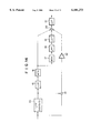
- FIG. 11A is a block diagram showing an apparatus for carrying out image processing with an 8-bit signal
- FIG. 11B is a block diagram showing an apparatus for carrying out image processing with a 10-bit signal
- FIG. 12A is a graph showing a pattern of an image signal obtained from the image processing with the 8-bit signal
- FIG. 12B is a graph showing a pattern of an image signal obtained from the image processing with the 10-bit signal
- FIG. 13 is a perspective view showing a developing section
- FIG. 14 is a block diagram showing an image processing section in which an unsharp mask processing is carried out.
- FIG. 15 is a graph showing the frequency characteristics of a processed image signal, which is obtained from image processing containing the unsharp mask processing.
- FIG. 1 is an explanatory view showing an embodiment of the image reproducing apparatus in accordance with the present invention.
- an image reproducing apparatus 1 which is the embodiment of the image reproducing apparatus in accordance with the present invention, comprises an image read-out section 1A and an image processing section 1B.
- the image read-out section 1A comprises a light source 2, and a light regulating device 3 for adjusting the amount of light having been produced by the light source 2.
- the image read-out section 1A also comprises an RGB filter 4 for converting the light, which has been produced by the light source 2, into R, G, and B three colors, and a mirror box 5 for diffusing the light, which has passed through the RGB filter 4, and irradiating it to film 6.
- the image read-out section 1A further comprises a lens 7 for forming an image of the light, which has passed through the film 6, on an area type of CCD image sensor 8.
- the image read-out operation is carried out with the area type of CCD image sensor 8.
- a technique for moving a line sensor with respect to the light may be employed.
- a technique for spot photometry using a drum scanner, or the like may be employed.
- a preliminary read-out operation and a final read-out operation are carried out.
- the detection intervals of the CCD image sensor 8 are set to be comparatively coarse, and a preliminary read-out image signal S P is thereby obtained.
- the final read-out operation is carried out.
- the detection intervals of the CCD image sensor 8 are set to be comparatively fine, and a final read-out image signal S Q is thereby obtained.
- the image processing section 1B comprises an amplifier 10 for amplifying the R, G, and B three color image signals, which have been detected by the CCD image sensor 8, and an analog-to-digital converter 11 for converting the amplified image signals into digital image signals.
- the image processing section 1B also comprises a look-up table (LUT) 12 for converting the digital image signals into image density signals, and frame memories 13R, 13G, and 13B, which respectively store the R, G, and B digital image signals having been converted into the image density signals.
- the image processing section 1B further comprises frame memories 14R, 14G, and 14B for respectively storing R, G, and B preliminary read-out image signals S P , which are obtained in cases where the preliminary read-out operation is carried out.
- the image processing section 1B still further comprises an LUT 15 for carrying out correction of gray balance, brightness, and gradation, which will be described later, on the digital image signals, and a matrix (MTX) 16 for correcting the image signals, which have been obtained from the processing carried out by the LUT 15, such that they may become the color signals capable of being reproduced in appropriate colors on a photosensitive material, which will be described later.
- the image processing section 1B also comprises an MTX 17 for converting the image signals, which have been corrected by the MTX 16, into a luminance, and a low-pass filter (LPF) 18 for forming an unsharp signal from the luminance.
- LPF low-pass filter
- the image processing section 1B further comprises an LUT 19 for compressing the dynamic range of the unsharp signal and thereby obtaining an unsharp image signal for the adjustment of the large area contrast, and an adder 20 for adding the original image signals and the unsharp image signal, which has been obtained from the dynamic range compressing process, to each other and thereby obtaining addition signals Sadd.
- the image processing section 1B still further comprises an LUT 21 for correcting the contrast (i.e., the large area contrast and the high frequency contrast) of the addition signals Sadd, i.e. for carrying out a gradation processing, and a digital-to-analog converter 22 for converting the signals, which have been obtained from the contrast correction, into analog signals.
- the image processing section 1B also comprises an LUT 23 for correcting the gradation of the preliminary read-out image signals S P , and a digital-to-analog converter 24 for converting the preliminary read-out image signals S P , which have been obtained from the gradation correction carried out by the LUT 23, into analog signals.
- the image processing section 1B further comprises a CRT display device 25 for reproducing a visible image from the preliminary read-out image signals S P having been obtained from the digital-to-analog conversion, and a mouse device 26 for operating the visible image, which is displayed on the CRT display device 25, in order to set ultimate parameters for the image.
- the image processing section 1B still further comprises an automatic set-up algorithm device 27 for calculating the histogram of the preliminary read-out image signals S P in the manner, which will be described later, and setting the parameters for the adjustments of the LUT 15, the LUT 19, the LUT 21, and the LUT 23 in accordance with the histogram.
- the LUT 12 is a transmittance-to-image density conversion table for converting the signals such that saturation may not be reached with respect to the image density range of the original image.
- the LUT 15 corrects the gray balance, the brightness, and the gradation.
- the LUT 15 comprises a gray balance adjustment table shown in FIG. 2A, a brightness correction table shown in FIG. 2B, and a ⁇ correction table shown in FIG. 2C, which are connected in series.
- the LUT 19 stores dynamic range compression tables having predetermined inclinations ⁇ shown in FIGS. 3A, 3B, 3C, 3D, and 3E.
- ⁇ takes a negative value.
- the dynamic range compression tables are calculated in accordance with the preliminary read-out image signals S P .
- the LUT 21 is a non-linear gradation conversion table and represents the relationship between the input signal and a processed image signal representing the reproduced image.
- the LUT 23 stores a linear gradation conversion table shown in FIG. 5. The inclination of the linear gradation conversion table is equal to 1+ ⁇ .
- the MTX 16 corrects the detected digital image signals such that they may become the color signals capable of being reproduced in appropriate colors on the photosensitive material. Specifically, the MTX 16 corrects the detected digital image signals such that they may be reproduced in appropriate colors by the combination of the spectral characteristics of the film 6 and the spectral characteristics of the photosensitive material, on which the visible image is reproduced ultimately.
- the MTX 17 converts the R, G, and B color image signals into a luminance. Specifically, the MTX 15 converts the R, G, and B color image signals into the luminance by using a value of one-third of the mean value of each color image signal or by using the YIQ base, or the like.
- the LPF 18 is the unsharp mask filter for blurring the luminance in two-dimensional directions and has the characteristics illustrated in FIG. 6. If the diameter of the unsharp mask is very small, the sharpness will be emphasized unnaturally, or overshooting of an edge in the image will become perceptible. If the diameter of the unsharp mask is very large, the drawbacks will occur in that the effects of the unsharp mask cannot be obtained appropriately when the primary object pattern is small, or in that a large amount of calculation is required and the scale of the apparatus cannot be kept small.
- the diameter of the half-width of the mask size should preferably fall within the range of approximately 0.3 mm to approximately 3 mm on the film, and should more preferably fall within the range of approximately 0.5 mm to approximately 2 mm on the film.
- the unsharp mask size should preferably be increased.
- the light is produced by the light source 2 of the image read-out section 1A.
- the light is converted to a predetermined amount of light by the light regulating device 3.
- the amount of light, which has passed through the minimum image density point in the image having been recorded on the film 6, is measured previously, and the light regulating device 3 adjusts the amount of light having been produced by the light source 2 such that the amount of light, which has passed through the minimum image density point in the image, may be slightly lower than the saturation level of the CCD image sensor 8.
- the light having been adjusted by the light regulating device 3 passes through the RGB filter 4, is diffused by the mirror box 5, and then impinges upon the film 6.
- the light passes through the film 6 and is thus modulated in accordance with the image information having been recorded on the film 6.
- the light passes through the lens 7 and impinges upon the CCD image sensor 8.
- the detection intervals of the CCD image sensor 8 are set to be comparatively coarse.
- the RGB filter 4 is changed over to R, G, and B, and three color preliminary read-out image signals S P representing the color image are thereby obtained.
- the three color preliminary read-out image signals S P are fed into the image processing section 1B. At the image processing section 1B, the processing is carried out in the manner described below.
- the preliminary read-out image signals S P obtained at the image read-out section 1A are weak, and are therefore amplified by the amplifier 10.
- the image signals are then converted into the digital preliminary read-out image signals S P by the analog-to-digital converter 11.
- the digital preliminary read-out image signals S P are converted into image density signals by the LUT 12 and are then respectively stored in the frame memories 14R, 14G, and 14B.
- the preliminary read-out image signals S P are read from the frame memories 14R, 14G, and 14B and are fed into the automatic set-up algorithm device 27 and the LUT 23.
- the automatic set-up algorithm device 27 the processing described below is carried out.
- FIG. 7 shows the histogram of the preliminary read-out image signals S P .
- the maximum luminance Ymax and the minimum luminance Ymin of the R, G, and B colors are calculated.
- the gray balance adjustment table shown in FIG. 2A which is to be utilized in the LUT 15, is set.
- the dynamic range compression tables for the dynamic range compressing process which is carried out in the LUT 19, are set.
- the dynamic range compression tables are set in the manner described below.
- the image signal and the ultimate print density are related to each other in the manner described below.
- the region, in which the object image pattern can be reproduced such that the details of the object image pattern may not become imperceptible due to insufficient gradation is the region G shown in FIG. 4. Therefore, in the digital image signal, if the object image pattern contained in the image is outside the range G, an image portion, such as a catch light portion, in which the signal value is large, will become white and its details will become imperceptible. Also, an image portion, in which the signal value is small, will become black and its details will become imperceptible. Thus the gray level of the portions of the image cannot be reproduced appropriately. Accordingly, in this embodiment, the rates of dynamic range compression are set in the manner described below such that the details of the very bright portion and the details of the very dark portion may not become imperceptible due to insufficient gradation in the print formed on the photosensitive material.
- the rates of dynamic range compression are set in accordance with the dynamic range having been calculated from the histogram shown in FIG. 7.
- the rates of dynamic range compression are set such that the dynamic range, i.e. the difference between the maximum luminance Ymax and the minimum luminance Ymin of the preliminary read-out image signals S P having been calculated from the histogram shown in FIG. 7, may become identical with the signal of the range G between Ymax' and Ymin' of the LUT 21. More specifically, if the dynamic range of the image signal is larger than the range G between Ymax' and Ymin', since the value of the gradation curve ⁇ corresponding to the region of the image signal, in which the signal value is larger than Ymax' (and which represents the highlight), converges, the details of the highlight will become imperceptible due to insufficient gradation in the reproduced image.
- the dynamic range i.e. the difference between the maximum luminance Ymax and the minimum luminance Ymin of the preliminary read-out image signals S P having been calculated from the histogram shown in FIG. 7
- the dynamic range of the image signal is larger than the range G between Ymax'
- the rate of dynamic range compression ⁇ l for the highlight and the rate of dynamic range compression ⁇ d are set such that the details of the highlight and the shadow may not become imperceptible.
- the rate of dynamic range compression ⁇ l is set such that the signal in the vicinity of the maximum luminance Ymax of the preliminary read-out image signals S P may be compressed to the level not higher than Ymax'.
- the rate of dynamic range compression ⁇ d is set such that the signal in the vicinity of the minimum luminance Ymin of the preliminary read-out image signals S P may be compressed to the level not lower than Ymin'.
- the rate of dynamic range compression ⁇ for the entire area of the image is set with the function ⁇ (DR) shown in FIG. 8, wherein DR is an acronym for the dynamic range.
- the function ⁇ (DR) has the characteristics such that, in cases where the dynamic range of the image signal is smaller than a threshold value DRth, the rate of compression may be equal to zero, i.e. the dynamic range compressing process may not be carried out. This is because, in cases where the dynamic range is small and the large area contrast of the image is low, if the dynamic range compressing process is carried out, the large area contrast of the image will become even lower, and the reproduced image will become imperceptible.
- the minimum image density should preferably be not reproduced in the reproduced image. Therefore, in FIG. 8, in cases where the dynamic range is larger than DRmax, ⁇ is clipped at the lower limit value ⁇ max.
- the tables for the dynamic range compressing process carried out in the LUT 19 are set.
- the dynamic range compression table for the entire area of the image is set in accordance with the rate of compression ⁇ having been set with the function shown in FIG. 8.
- the dynamic range compression table for the entire area of the image is represented by the monotonously decreasing function in which the image signal serves as the variable.
- the function f( ⁇ ) representing the dynamic range compression table is set by the inclination ⁇ around a signal value YO.
- a value which falls within the range of 0.50 to 0.70 and corresponds to approximately the same image density as the flesh color, preferably a value of 0.6, is set as the signal value YO.
- the dynamic range compression does not affect the brightness correction with respect to the aforesaid image density, and therefore the function for the brightness correction and the function for the dynamic range compressing process can be clearly separated from each other.
- the setting of parameters in the automatic set-up algorithm device 27 becomes easy.
- the advantage can be obtained in that, in cases where the brightness of the primary image portion could not be adjusted appropriately with the brightness adjusting process, the dynamic range compressing process serves such that the primary image portion may be set to be a value close to YO.
- f l ( ⁇ l ) and f d ( ⁇ d ) are the functions shown in FIGS. 3D and 3E, which are discontinuous at the point YO, even if no contour is embedded in the original image, an artifact will often occur in the image density region corresponding to the point YO in the processed image.
- the functions f l ( ⁇ l ) and f d ( ⁇ d ) are set as shown in FIGS. 3B and 3C such that the differential coefficient may be continuous at the point YO, such an artifact can be prevented from occurring.
- f l ( ⁇ l ) and f d ( ⁇ d ) are the straight lines having an end point at YO. Such that the occurrence of an artifact may be restricted, they should preferably be set as shown in FIGS. 3B and 3C such that the differential coefficient may be continuous.
- the rates of dynamic range compression are set in the manner described above.
- the dynamic range compressing process is then carried out on the preliminary read-out image signals S P by using the rates of dynamic range compression.
- the preliminary read-out image signals S P which have been obtained from the dynamic range compressing process, are then fed into the LUT 23.
- the preliminary read-out image signals S P are subjected to the gradation processing in the LUT 23, converted into analog signals by the digital-to-analog converter 24, and then used for reproducing a visible image on the monitor 25.
- the visible image, which is displayed on the monitor 25, is the image reproduced from the preliminary read-out image signals S P . It is necessary for the effects of the dynamic range compression to be reflected on the displayed image.
- the problems will occur in that the scale of the image reproducing system cannot be kept small.
- the gradation conversion be carried out on the preliminary read-out image signals S P by using a simple gradation conversion table shown in FIG. 5, in which a rate of dynamic range compression ⁇ +1 is set as the inclination, and that a visible image be reproduced from the preliminary read-out image signals S P having been obtained from the gradation conversion and displayed on the monitor 25. Therefore, the information representing the gradation conversion table shown in FIG. 5 is stored in the LUT 23.
- the gradation conversion is carried out on using the gradation conversion table stored in the LUT 23. A visible image is then reproduced from the resulting signals and displayed on the monitor 25. In this manner, confirmation of the effects of the rates of dynamic range compression can be carried out such that the scale of the image reproducing system does not become large.
- FIG. 9 shows how the visible image represented by the preliminary read-out image signals S P is displayed on the monitor 25.
- An adjustment section 25A in which the rates of compression of the displayed image are adjusted with the mouse device 26, is displayed on the monitor 25.
- the rates of compression are adjusted by operating the mouse device 26, and the scene of the image represented by the preliminary read-out image signals S P is discriminated.
- the rates of dynamic range compression are thereby adjusted finely.
- the information representing the rates of dynamic range compression having thus been adjusted is fed into the automatic set-up algorithm device 27, and the dynamic range compression tables to be used in the LUT 19 are ultimately set.
- the operator views the image displayed on the monitor 25 and adjusts the rates of compression having been set by the automatic set-up algorithm device 27.
- the automatic set-up algorithm device 27 may be constituted such that it may discriminates the scene of the image and may automatically adjust the rates of dynamic range compression.
- the light is produced by the light source 2 of the image read-out section 1A.
- the light is converted to a predetermined amount of light by the light regulating device 3.
- the amount of light adjusted by the light regulating device 3 is set in accordance with the values of the preliminary read-out image signals S P having been stored in the frame memories 14R, 14G, and 14B.
- the light, having been adjusted by the light regulating device 3, passes through the RGB filter 4, is diffused by the mirror box 5, and then impinges upon the film 6.
- the light passes through the film 6 and is thus modulated in accordance with the image information having been recorded on the film 6. Thereafter, the light passes through the lens 7 and impinges upon the CCD image sensor 8.
- the light is photoelectrically converted by the CCD image sensor 8 into an image signal, which represents the image having been recorded on the film 6.
- the detection intervals of the CCD image sensor 8 are set to be comparatively fine.
- the RGB filter 4 is changed over to R, G, and B, and three color final read-out image signals S Q representing the color image are thereby obtained.
- the three color final read-out image signals S Q are fed into the image processing section 1B. At the image processing section 1B, the processing is carried out in the manner described below.
- the final read-out image signals S Q obtained at the image read-out section 1A are weak, and are therefore amplified by the amplifier 10.
- the image signals are then converted into the digital final read-out image signals S Q by the analog-to-digital converter 11.
- the digital final read-out image signals S Q are converted into image density signals by the LUT 12 and are then respectively stored in the frame memories 13R, 13G, and 13B.
- the final read-out image signals S Q are read from the frame memories 13R, 13G, and 13B and fed into the LUT 15.
- the correction of the gray balance, the correction of the brightness, and the correction of the gradation are carried out on the final read-out image signals S Q in accordance with the gray balance adjustment table shown in FIG. 2A, the brightness correction table shown in FIG. 2B, and the gradation correction table shown in FIG. 2C, which have been determined by the automatic set-up algorithm device 27.
- the final read-out image signals S Q having thus been corrected by the LUT 15 are fed into the MTX 16 and subjected to color correction.
- the MTX 16 corrects the digital image signals such that the colors may be reproduced by the combination of the spectral characteristics of the film 6 and the spectral characteristics of the photosensitive material, on which the visible image is reproduced ultimately.
- the final read-out image signals S Q having been obtained from the color correction carried out by the MTX 16 are fed into the adder 20 and the MTX 17.
- the luminance is formed from the R, G, and B signals.
- the R, G, and B color image signals are converted into the luminance by using a value of one-third of the mean value of each color image signal or by using the YIQ base, or the like.
- the luminance is to be formed with the YIQ base
- only the Y components of the YIQ base are calculated from the R, G, and B signal values. The calculation is carried out with Formula (2) shown below.
- the luminance, which has thus been obtained, is then converted into the unsharp mask signal by the LPF 18.
- the unsharp mask signal is then fed into the LUT 19.
- the dynamic range compressing process is carried out in accordance with the function f t ( ⁇ ) for the dynamic range compression, which has been set by the automatic set-up algorithm device 27.
- the unsharp mask signal, which has been obtained from the dynamic range compressing process is fed into the adder 20.
- the adder 20 the unsharp mask signal and the final read-out image signals S Q , which have been obtained from the color correction carried out by the MTX 16, are added together, and the addition signals Sadd are thereby obtained.
- the addition signals Sadd the dynamic range of the low frequency components of the image has been compressed.
- the addition signals Sadd having thus been obtained are fed into the LUT 21.
- the gradation processing is carried out in accordance with the ultimate output medium, such as a photosensitive material. The processed image signals are obtained in this manner.
- FIG. 10 shows the frequency characteristics of the processed image signals.
- the passing band of the LPF 18 corresponds to the large area contrast.
- the high frequency contrast corresponds to the components of higher frequency than the passing band of the LPF 18, and therefore is not subjected to the compression with the LUT 19. Therefore, the image reproduced from the processed image signals can be obtained such that the dynamic range may have been compressed while the high frequency contrast is being kept.
- the image processing which corresponds to the shutting light technique in the operation of conventional analog printing, can be carried out.
- FIG. 11A is a block diagram showing an apparatus for carrying out the image processing with an 8-bit signal.
- FIG. 11B is a block diagram showing an apparatus for carrying out the image processing with a 10-bit signal.
- the number of bits of the image signal is one of the important factors that determine the quantization level of the image. If the quantization level of the image is low, an artifact will occur in the reproduced image. For example, as illustrated in FIG. 11A, if the number of bits of the image signal is set to be 8 bits (256 gradation levels) in all operations, an artifact will often occur in the reproduced image.
- the number of bits of the image signal before being fed into the LUT 21 is converted from 8 bits to 10 bits, the gradation processing is carried out on the 10-bit image signal in the LUT 21, and the number of bits of the image signal is thereafter returned to 8 bits.
- the occurrence of the artifact can be restricted.
- 1 LSB obtained after the processing has been carried out by the LUT 19 becomes 1/4 of 1 LSB obtained in the case of the 8-bit image signal, and therefore the signal resulting from the gradation conversion carried out by the LUT 21 becomes equal to 1.5 ⁇ 1/4 of the dynamic range compressed signal.
- the number of bits of the image signal, which is subjected to the dynamic range compressing process in the LUT 19 is set to be at least 10 bits, the occurrence of the artifact can be restricted to a level lower than when the processing is carried out on the 8-bit image signal.
- the processed image signals having thus been obtained from the LUT 21 are fed into the digital-to-analog converter 22 and converted into analog signals.
- the analog signals obtained from the digital-to-analog converter 22 are fed into an image-wise exposure section 98 shown in FIG. 13. At the image-wise exposure section 98, the processing described below is carried out.
- the image signals having been obtained from the image processing section 1B are fed into acousto-optic modulator (AOM) drivers (not shown).
- AOM acousto-optic modulator
- the AOM drivers operate AOM's 104R, 104G, and 104B of the image-wise exposure section 98 such that light beams may be modulated in accordance with the received image signals.
- the image-wise exposure section 98 comprises a light source 102R for producing a light beam having wavelengths of a narrow-band range corresponding to the exposure of a red-sensitive layer of the photosensitive material A, a light source 102G for producing a light beam having wavelengths of a narrow-band range corresponding to the exposure of a green-sensitive layer of the photosensitive material A, and a light source 102B for producing a light beam having wavelengths of a narrow-band range corresponding to the exposure of a blue-sensitive layer of the photosensitive material A.
- a light source 102R for producing a light beam having wavelengths of a narrow-band range corresponding to the exposure of a red-sensitive layer of the photosensitive material A
- a light source 102G for producing a light beam having wavelengths of a narrow-band range corresponding to the exposure of a green-sensitive layer of the photosensitive material A
- a light source 102B for producing a light beam having wavelengths of a narrow-band range corresponding to the exposure of
- the image-wise exposure section 98 also comprises the AOM's 104R, 104G, and 104B for respectively modulating the light beams, which have been produced by the light sources 102R, 102G, and 102B, in accordance with the recorded image information.
- the image-wise exposure section 98 further comprises a rotating polygon mirror 96 serving as a light deflector, an f ⁇ lens 106, and a sub-scanning conveyance means 108 for conveying the photosensitive material A in a sub-scanning direction.
- the light beams having been produced by the light sources 102R, 102G, and 102B travel along directions at different angles and impinge upon the corresponding AOM's 104R, 104G, and 104B.
- various types of light beam sources may be utilized, which are capable of producing the light beams having predetermined wavelengths corresponding to the sensitive layers of the photosensitive material A.
- various types of semiconductor lasers, SHG lasers, or gas lasers, such as He--Ne lasers may be used.
- the light sources may be constituted as a light beam combining optical system.
- the AOM's 104R, 104G, and 104B receive drive signals r, g, and b, which are for red, green, and blue colors and correspond to the recorded image information, from the AOM drivers.
- the AOM's 104R, 104G, and 104B thus modulate the intensities of the light beams, which impinge thereupon, in accordance with the recorded image information.
- the light beams are thus deflected in main scanning directions, which are indicated by the double headed arrow x in FIG. 13.
- the light beams are regulated by the f ⁇ lens 106 such that they may be imaged in a predetermined beam shape at a predetermined scanning position z.
- the light beams thus impinge upon the photosensitive material A.
- a resonant scanner, a galvanometer mirror, or the like may be utilized as the light deflector.
- the image-wise exposure section 98 may be provided with a light beam shaping means and an optical system for compensation for inclinations of the surfaces of the light deflector.
- a roll of the photosensitive material A is located at a predetermined position such that it may be shielded from light.
- the photosensitive material A is delivered from the roll by a delivery device, such as delivery rollers, and is cut to a predetermined length by a cutter (not shown).
- the sub-scanning device 108 is constituted by a pair of rollers 108a, 108a and a pair of rollers 108b, 108b. The two pairs of rollers are located with the scanning position z intervening therebetween.
- the pair of rollers 108a, 108a and the pair of rollers 108b, 108b support the cut photosensitive material A at the scanning position z and convey it in the sub-scanning direction, which is approximately normal to the main scanning directions and is indicated by the arrow y in FIG. 13.
- the light beams are deflected in the main scanning directions. Therefore, the entire area of the photosensitive material A, which is being conveyed in the sub-scanning direction, is scanned with the light beams in the two-dimensional directions. In this manner, an image represented by the image signals, which have been processed by the LUT 21, is reproduced on the photosensitive material A.
- the photosensitive material A which has been exposed to the light beams, is then conveyed by a pair of conveying rollers 110, 110 into a developing section 100.
- the photosensitive material A is subjected to development processing, and a finished print P is thereby obtained.
- the developing section 100 is constituted of a color development tank 112, a bleach-fix tank 114, a washing tanks 116a, 116b, and 116c, and a drying means 118.
- the photosensitive material A is subjected to predetermined processing in the respective processing tanks, and the finished print P is thereby obtained.
- the light beams are modulated by the AOM's 104R, 104G, and 104B.
- the light beams may be directly modulated in accordance with the recorded image information.
- a combination of an exposure drum, which supports the photosensitive material at the scanning position, and two nipping rollers, which are located with the scanning position intervening therebetween may be utilized as the sub-scanning conveyance means.
- a drum scanner may be utilized.
- the photosensitive material is wound around a drum, and the light beams are caused to impinge upon a single point on the photosensitive material.
- the drum is rotated and, at the same time, is moved along the axis of the drum.
- a surface exposure operation using a surface light source and a liquid crystal shutter may be employed.
- the exposure operation may be carried out by using a linear light source, such as an LED array.
- the photosensitive material is cut into a sheet before being exposed to the light beams.
- the photosensitive material may be exposed to the light beams without being cut into sheets, and may be cut into sheets before being processed at the developing section 100 or after being processed at the developing section 100.
- the visible image is reproduced at the developing section 100. Even if the visible image is the one reproduced from a backlighted scene, the details of the pattern of the person will not become imperceptible due to insufficient gradation in the visible image. Also, the details of the bright background pattern will not become imperceptible. Further, even if the visible image is the one reproduced from an image having been recorded by using an electronic flash, a visible reproduced image can be obtained such that both the details of a pattern of a person, which is located on the foreground side in the image, and the details of a background, which is located far away behind the pattern of the person, may be prevented from becoming imperceptible due to insufficient gradation. In this manner, an image having been subjected to the appropriate dynamic range compressing process can be obtained.
- the selection of the factor of the MTX 17 is the only possible method for controlling the color reproducibility. Therefore, in cases where the color reproducibility is adjusted, both the brightness and the color reproducibility changes simultaneously at an edge in the image, and a print having an unnatural feeling is obtained.
- the MTX 17 is constituted in order to convert the color image signals into the luminance. Therefore, with the embodiment of the image reproducing apparatus in accordance with the present invention, even though the brightness of an edge of an object changes, the color reproducibility at the edge does not change. Accordingly, a print having a natural feeling can be obtained.
- LUT 21 has the nonlinear characteristics. Therefore, the gradation correction can be carried out also for the portions of nonlinear characteristics on the original image film (e.g., an over-exposure portion and an under-exposure portion).
- the preliminary read-out operation is carried out in order to obtain the preliminary read-out image signals S P , and the tables in the LUT 15, the LUT 19, and the LUT 21 are set by the automatic set-up algorithm device 27 in accordance with the preliminary read-out image signals S P .
- the preliminary read-out operation may not be carried out, and the signals corresponding to the final read-out image signals S Q in the aforesaid embodiment may be obtained with a single read-out operation.
- the tables in the LUT 15, the LUT 19, and the LUT 21 may be set by the automatic set-up algorithm device 27.
- the processing of the image signals can be carried out by carrying out only a single operation for reading out the image from the film 6. Therefore, the image processing can be carried out quickly. Also, since it is sufficient for a single image read-out operation to be carried out, it is not necessary for the film to be moved between the scanning operation and the exposure operation as in the apparatuses described in Japanese Unexamined Patent Publication Nos. 58(1983)-66929 and 64(1989)-35542 and Japanese Patent Publication No. 64(1989)-10819. Accordingly, no deviation occurs between the image signals and the mask signals due to an error occurring in the movement distance, and a reproduced image having good quality can be obtained reliably.
- a filtering process may be carried out on the final read-out image signals S Q , which have been stored in the frame memories 13R, 13G, and 13B. Unsharp mask signals Sus of the final read-out image signals S Q may thereby be obtained.
- the unsharp mask signals Sus may then be subtracted from the original image signals, and difference signals may thereby be obtained.
- the difference signals may be multiplied by a predetermined emphasis coefficient.
- the thus obtained difference signals, the original image signals, and the image signal, which has been obtained from the dynamic range compressing process carried out in the LUT 19, may be added together.
- the resulting signals may then be fed into the LUT 21 and subjected to the gradation processing, and the processed image signals may thereby be obtained.
- the unsharp mask processing is carried out with Formula (3) shown below.
- Sorg represents the original image signal
- Sus represents the unsharp mask signal obtained with the unsharp mask
- ⁇ represents the emphasis coefficient
- Sproc represents the signal obtained from the unsharp mask processing.
- the processed image signals which are obtained by carrying out the unsharp mask processing even further, have the frequency characteristics shown in FIG. 15. As illustrated in FIG. 15, the processed image signals have the frequency characteristics such that the dynamic range of the low frequency components L may have been compressed by the aforesaid dynamic range compressing process, and such that the high frequency components H may have been emphasized even further. Accordingly, in such cases, a reproduced image in which the sharpness has been emphasized can be obtained.
Abstract
Description
f.sub.t (α)=f(α)+f.sub.l (α.sub.l)+f.sub.d (α.sub.d)(1)
Y=0.3R+0.59G+0.11B (2)
Sproc=Sorg+β(Sorg-Sus) (3)
Claims (10)
Priority Applications (1)
| Application Number | Priority Date | Filing Date | Title |
|---|---|---|---|
| US09/503,334 US6694052B1 (en) | 1995-10-31 | 2000-02-14 | Image reproducing method and apparatus |
Applications Claiming Priority (2)
| Application Number | Priority Date | Filing Date | Title |
|---|---|---|---|
| JP28314495A JP3669448B2 (en) | 1995-10-31 | 1995-10-31 | Image reproduction method and apparatus |
| JP7-283144 | 1995-10-31 |
Related Child Applications (1)
| Application Number | Title | Priority Date | Filing Date |
|---|---|---|---|
| US09/503,334 Continuation US6694052B1 (en) | 1995-10-31 | 2000-02-14 | Image reproducing method and apparatus |
Publications (1)
| Publication Number | Publication Date |
|---|---|
| US6101273A true US6101273A (en) | 2000-08-08 |
Family
ID=17661798
Family Applications (1)
| Application Number | Title | Priority Date | Filing Date |
|---|---|---|---|
| US08/741,722 Expired - Lifetime US6101273A (en) | 1995-10-31 | 1996-10-31 | Image reproducing method and apparatus |
Country Status (4)
| Country | Link |
|---|---|
| US (1) | US6101273A (en) |
| EP (2) | EP1359742B1 (en) |
| JP (1) | JP3669448B2 (en) |
| DE (2) | DE69637090T2 (en) |
Cited By (74)
| Publication number | Priority date | Publication date | Assignee | Title |
|---|---|---|---|---|
| US20010030685A1 (en) * | 1999-12-30 | 2001-10-18 | Darbin Stephen P. | Method and apparatus for digital film processing using a scanning station having a single sensor |
| US20010031084A1 (en) * | 1999-12-17 | 2001-10-18 | Cannata Philip E. | Method and system for selective enhancement of image data |
| US20010040701A1 (en) * | 2000-02-03 | 2001-11-15 | Edgar Albert D. | Photographic film having time resolved sensitivity distinction |
| US20010041004A1 (en) * | 2000-04-14 | 2001-11-15 | Trusight Ltd. | Method for automated high speed improvement of digital color images |
| WO2002025589A1 (en) * | 2000-09-20 | 2002-03-28 | Nik Multimedia, Inc. | Digital image sharpening system |
| US6380539B1 (en) | 1997-01-30 | 2002-04-30 | Applied Science Fiction, Inc. | Four color trilinear CCD scanning |
| US20020051215A1 (en) * | 1999-12-30 | 2002-05-02 | Thering Michael R. | Methods and apparatus for transporting and positioning film in a digital film processing system |
| US6393160B1 (en) | 1998-03-13 | 2002-05-21 | Applied Science Fiction | Image defect correction in transform space |
| US6404516B1 (en) | 1999-02-22 | 2002-06-11 | Applied Science Fiction, Inc. | Parametric image stitching |
| US20020080409A1 (en) * | 1999-12-31 | 2002-06-27 | Keyes Michael P. | Digital film processing method |
| US20020106134A1 (en) * | 2000-09-22 | 2002-08-08 | Dundon Thomas A. | Multiple-orientation image defect detection and correction |
| US6437358B1 (en) | 1999-02-04 | 2002-08-20 | Applied Science Fiction, Inc. | Apparatus and methods for capturing defect data |
| US6442301B1 (en) | 1997-01-06 | 2002-08-27 | Applied Science Fiction, Inc. | Apparatus and method for defect channel nulling |
| US6439784B1 (en) | 1999-08-17 | 2002-08-27 | Applied Science Fiction, Inc. | Method and system for using calibration patches in electronic film processing |
| US20020118402A1 (en) * | 2000-09-19 | 2002-08-29 | Shaw Timothy C. | Film bridge for digital film scanning system |
| US6443639B1 (en) | 1999-06-29 | 2002-09-03 | Applied Science Fiction, Inc. | Slot coater device for applying developer to film for electronic film development |
| US6447178B2 (en) | 1999-12-30 | 2002-09-10 | Applied Science Fiction, Inc. | System, method, and apparatus for providing multiple extrusion widths |
| US20020126327A1 (en) * | 2000-09-21 | 2002-09-12 | Edgar Albert D. | Method and system for improving scanned image detail |
| US6461061B2 (en) | 1999-12-30 | 2002-10-08 | Applied Science Fiction, Inc. | System and method for digital film development using visible light |
| US20020146171A1 (en) * | 2000-10-01 | 2002-10-10 | Applied Science Fiction, Inc. | Method, apparatus and system for black segment detection |
| US20020159165A1 (en) * | 2000-09-22 | 2002-10-31 | Ford Gordon D. | Lens focusing device, system and method for use with multiple light wavelengths |
| US6475711B1 (en) | 1999-12-31 | 2002-11-05 | Applied Science Fiction, Inc. | Photographic element and digital film processing method using same |
| US6487321B1 (en) | 1999-09-16 | 2002-11-26 | Applied Science Fiction | Method and system for altering defects in a digital image |
| US6498867B1 (en) | 1999-10-08 | 2002-12-24 | Applied Science Fiction Inc. | Method and apparatus for differential illumination image-capturing and defect handling |
| US6503002B1 (en) | 1996-12-05 | 2003-01-07 | Applied Science Fiction, Inc. | Method and apparatus for reducing noise in electronic film development |
| US6505977B2 (en) | 1999-12-30 | 2003-01-14 | Applied Science Fiction, Inc. | System and method for digital color dye film processing |
| US20030011827A1 (en) * | 1999-12-29 | 2003-01-16 | Applied Science Fiction | Distinguishing positive and negative films system and method |
| US6512601B1 (en) | 1998-02-23 | 2003-01-28 | Applied Science Fiction, Inc. | Progressive area scan in electronic film development |
| US20030052979A1 (en) * | 2001-09-03 | 2003-03-20 | Kabushiki Kaisha Toyota Chuo Kenkyusho | Image processing method and apparatus |
| US6540416B2 (en) | 1999-12-30 | 2003-04-01 | Applied Science Fiction, Inc. | System and method for digital film development using visible light |
| US6545636B1 (en) * | 2000-09-11 | 2003-04-08 | Sienna Imaging, Inc. | Photographic process printer using a linear digital exposure engine for printing upon cut-sheet paper |
| US6554504B2 (en) | 1999-12-30 | 2003-04-29 | Applied Science Fiction, Inc. | Distributed digital film processing system and method |
| US6558052B2 (en) | 1997-01-30 | 2003-05-06 | Applied Science Fiction, Inc. | System and method for latent film recovery in electronic film development |
| US6563531B1 (en) * | 1998-03-12 | 2003-05-13 | Fuji Photo Film Co., Ltd. | Image processing method |
| US20030099407A1 (en) * | 2001-11-29 | 2003-05-29 | Yuki Matsushima | Image processing apparatus, image processing method, computer program and storage medium |
| US20030118249A1 (en) * | 2001-04-19 | 2003-06-26 | Edgar Albert D. | Method, system and software for correcting image defects |
| US6590679B1 (en) | 1998-02-04 | 2003-07-08 | Applied Science Fiction, Inc. | Multilinear array sensor with an infrared line |
| US6594041B1 (en) | 1998-11-20 | 2003-07-15 | Applied Science Fiction, Inc. | Log time processing and stitching system |
| US6593558B1 (en) | 1996-05-10 | 2003-07-15 | Applied Science Fiction, Inc. | Luminance-priority electronic color image sensor |
| US20030133710A1 (en) * | 2001-07-16 | 2003-07-17 | Winberg Paul N. | System and method for digital film development using visible light |
| US6599036B2 (en) | 2000-02-03 | 2003-07-29 | Applied Science Fiction, Inc. | Film processing solution cartridge and method for developing and digitizing film |
| US20030147110A1 (en) * | 2002-01-31 | 2003-08-07 | Eastman Kodak Company | Image color balance for scanners using an illumination spectral sensor |
| US20030150918A1 (en) * | 2002-02-08 | 2003-08-14 | Ryuji Nogami | Illumination apparatus and image reading apparatus |
| US6614946B1 (en) | 1999-10-08 | 2003-09-02 | Eastman Kodak Company | System and method for correcting defects in digital images through selective fill-in from surrounding areas |
| US6619863B2 (en) | 2000-02-03 | 2003-09-16 | Eastman Kodak Company | Method and system for capturing film images |
| US6683995B2 (en) | 1999-12-23 | 2004-01-27 | Eastman Kodak Company | Method and apparatus for correcting large defects in digital images |
| US20040028288A1 (en) * | 2002-01-14 | 2004-02-12 | Edgar Albert D. | Method, system, and software for improving signal quality using pyramidal decomposition |
| US6704458B2 (en) | 1999-12-29 | 2004-03-09 | Eastman Kodak Company | Method and apparatus for correcting heavily damaged images |
| US20040047585A1 (en) * | 2000-12-05 | 2004-03-11 | Duong Dung T. | Light transfer device and system |
| US20040047514A1 (en) * | 2002-09-05 | 2004-03-11 | Eastman Kodak Company | Method for sharpening a digital image |
| US6707557B2 (en) | 1999-12-30 | 2004-03-16 | Eastman Kodak Company | Method and system for estimating sensor dark current drift and sensor/illumination non-uniformities |
| US6711302B1 (en) | 1999-10-20 | 2004-03-23 | Eastman Kodak Company | Method and system for altering defects in digital image |
| US6720560B1 (en) | 1999-12-30 | 2004-04-13 | Eastman Kodak Company | Method and apparatus for scanning images |
| US6733960B2 (en) | 2001-02-09 | 2004-05-11 | Eastman Kodak Company | Digital film processing solutions and method of digital film processing |
| US6760484B1 (en) * | 2000-01-26 | 2004-07-06 | Hewlett-Packard Development Company, L.P. | Method for improved contrast mapping of digital images |
| US6781620B1 (en) | 1999-03-16 | 2004-08-24 | Eastman Kodak Company | Mixed-element stitching and noise reduction system |
| US6788335B2 (en) | 1999-12-30 | 2004-09-07 | Eastman Kodak Company | Pulsed illumination signal modulation control & adjustment method and system |
| US6786655B2 (en) | 2000-02-03 | 2004-09-07 | Eastman Kodak Company | Method and system for self-service film processing |
| US6813392B2 (en) | 1999-12-30 | 2004-11-02 | Eastman Kodak Company | Method and apparatus for aligning multiple scans of the same area of a medium using mathematical correlation |
| US6862117B1 (en) | 1999-12-30 | 2005-03-01 | Eastman Kodak Company | Method and apparatus for reducing the effect of bleed-through on captured images |
| US20050046902A1 (en) * | 2003-08-28 | 2005-03-03 | Fuji Photo Film Co., Ltd. | Image processing apparatus, method and program |
| US20050047650A1 (en) * | 2003-08-25 | 2005-03-03 | Fuji Photo Film Co., Ltd. | Image processing apparatus, method and program |
| US20050128474A1 (en) * | 1999-12-30 | 2005-06-16 | Young Robert S.Jr. | Method and apparatus to pre-scan and pre-treat film for improved digital film processing handling |
| US20050135665A1 (en) * | 1998-09-18 | 2005-06-23 | Canon Kabushiki Kaisha | Image processing apparatus, image processing method, and recording medium |
| US6924911B1 (en) | 1999-10-12 | 2005-08-02 | Eastman Kodak Company | Method and system for multi-sensor signal detection |
| US20050218295A1 (en) * | 1999-05-10 | 2005-10-06 | Minolta Co., Ltd. | Image-sensing apparatus with dynamic range adaptation functionality |
| US6990251B2 (en) * | 2000-02-03 | 2006-01-24 | Eastman Kodak Company | Method, system, and software for signal processing using sheep and shepherd artifacts |
| US7010160B1 (en) * | 1998-06-16 | 2006-03-07 | Konica Minolta Co., Ltd. | Backlight scene judging method |
| US20060182337A1 (en) * | 2000-06-28 | 2006-08-17 | Ford Benjamin C | Method and apparatus for improving the quality of reconstructed information |
| US20070182830A1 (en) * | 2006-01-31 | 2007-08-09 | Konica Minolta Holdings, Inc. | Image sensing apparatus and image processing method |
| US20080056705A1 (en) * | 2006-08-31 | 2008-03-06 | Micron Technology, Inc. | Backlit subject detection in an image |
| US20080225313A1 (en) * | 2007-03-12 | 2008-09-18 | Fujifilm Corporation | Image processing apparatus and method and computer-readable recording medium having stored therein the program |
| US20080297460A1 (en) * | 2007-05-31 | 2008-12-04 | Peng Huajun | Method of displaying a low dynamic range image in a high dynamic range |
| US10776906B2 (en) | 2017-09-07 | 2020-09-15 | Konica Minolta, Inc. | Radiographic image processing device, storage medium, and radiographic image processing method |
Families Citing this family (9)
| Publication number | Priority date | Publication date | Assignee | Title |
|---|---|---|---|---|
| DE69736347T2 (en) * | 1997-05-09 | 2007-07-12 | Stmicroelectronics S.R.L., Agrate Brianza | Digital photographing apparatus with an image processing apparatus |
| EP0886437B1 (en) | 1997-06-17 | 2004-11-24 | Seiko Epson Corporation | Method and apparatus for colour adjustment |
| DE69915721D1 (en) * | 1998-01-28 | 2004-04-29 | Konishiroku Photo Ind | Image processing device |
| US6285798B1 (en) * | 1998-07-06 | 2001-09-04 | Eastman Kodak Company | Automatic tone adjustment by contrast gain-control on edges |
| US6244710B1 (en) | 1998-12-30 | 2001-06-12 | Canon Kabushiki Kaisha | Ophthalmogical photographing apparatus |
| JP3581270B2 (en) * | 1999-03-26 | 2004-10-27 | ノーリツ鋼機株式会社 | Image processing apparatus, image processing method, and recording medium recording image processing program |
| GB0009135D0 (en) * | 2000-04-13 | 2000-05-31 | Fujifilm Electronic Imaging Li | Automatic optimisation of scan conditions |
| JP4505356B2 (en) * | 2005-03-14 | 2010-07-21 | 富士フイルム株式会社 | Image processing apparatus, image processing method and program thereof |
| EP2288903A4 (en) * | 2008-05-16 | 2012-03-21 | Biomedical Photometrics Inc | Imaging system with dynamic range maximization |
Citations (8)
| Publication number | Priority date | Publication date | Assignee | Title |
|---|---|---|---|---|
| GB2069794A (en) * | 1980-01-21 | 1981-08-26 | Dainippon Screen Mfg | Picture signal pre-processing method |
| US4340911A (en) * | 1979-02-28 | 1982-07-20 | Fuji Photo Film Co., Ltd. | Image gradation processing method and apparatus for mammogram copying system |
| US4731662A (en) * | 1985-03-21 | 1988-03-15 | Canon Kabushiki Kaisha | Image processing method for processing an image signal differently depending on the range of an image characteristic thereof relative to the range within which an output device can reproduce the image characteristic |
| EP0377386A2 (en) * | 1989-01-05 | 1990-07-11 | Eastman Kodak Company | An interactive dynamic range adjustment system for printing digital images |
| US5123059A (en) * | 1987-09-28 | 1992-06-16 | Dainippon Screen Mfg. Co., Ltd. | Gradation converting circuit employing lookup table |
| DE4309879A1 (en) * | 1992-04-06 | 1993-10-21 | Hell Ag Linotype | Analysis of image boundaries in scanning of colour images - determines frequency distribution of brightness values to generate maximum and minimum brightness limits |
| US5351306A (en) * | 1991-09-06 | 1994-09-27 | Siemens Aktiengesellschaft | Apparatus for reproducing video signals on a monitor |
| US5414538A (en) * | 1993-10-07 | 1995-05-09 | Xerox Corporation | Image-dependent exposure enhancement |
Family Cites Families (4)
| Publication number | Priority date | Publication date | Assignee | Title |
|---|---|---|---|---|
| DE2820965A1 (en) | 1978-05-12 | 1979-11-15 | Agfa Gevaert Ag | PHOTOGRAPHIC COPY DEVICE |
| US4394089A (en) | 1981-09-23 | 1983-07-19 | Logetronics, Inc. | Color photoprinting with a scanning memory mask |
| JPH087379B2 (en) | 1987-07-31 | 1996-01-29 | 富士写真フイルム株式会社 | Photo printing equipment |
| JP3086352B2 (en) | 1993-02-16 | 2000-09-11 | 富士写真フイルム株式会社 | Gray balance correction method |
-
1995
- 1995-10-31 JP JP28314495A patent/JP3669448B2/en not_active Expired - Fee Related
-
1996
- 1996-10-30 EP EP03016913A patent/EP1359742B1/en not_active Expired - Lifetime
- 1996-10-30 DE DE69637090T patent/DE69637090T2/en not_active Expired - Lifetime
- 1996-10-30 EP EP96117418A patent/EP0772342B1/en not_active Expired - Lifetime
- 1996-10-30 DE DE69633218T patent/DE69633218T2/en not_active Expired - Lifetime
- 1996-10-31 US US08/741,722 patent/US6101273A/en not_active Expired - Lifetime
Patent Citations (9)
| Publication number | Priority date | Publication date | Assignee | Title |
|---|---|---|---|---|
| US4340911A (en) * | 1979-02-28 | 1982-07-20 | Fuji Photo Film Co., Ltd. | Image gradation processing method and apparatus for mammogram copying system |
| GB2069794A (en) * | 1980-01-21 | 1981-08-26 | Dainippon Screen Mfg | Picture signal pre-processing method |
| US4731662A (en) * | 1985-03-21 | 1988-03-15 | Canon Kabushiki Kaisha | Image processing method for processing an image signal differently depending on the range of an image characteristic thereof relative to the range within which an output device can reproduce the image characteristic |
| US5123059A (en) * | 1987-09-28 | 1992-06-16 | Dainippon Screen Mfg. Co., Ltd. | Gradation converting circuit employing lookup table |
| EP0377386A2 (en) * | 1989-01-05 | 1990-07-11 | Eastman Kodak Company | An interactive dynamic range adjustment system for printing digital images |
| US5012333A (en) * | 1989-01-05 | 1991-04-30 | Eastman Kodak Company | Interactive dynamic range adjustment system for printing digital images |
| US5351306A (en) * | 1991-09-06 | 1994-09-27 | Siemens Aktiengesellschaft | Apparatus for reproducing video signals on a monitor |
| DE4309879A1 (en) * | 1992-04-06 | 1993-10-21 | Hell Ag Linotype | Analysis of image boundaries in scanning of colour images - determines frequency distribution of brightness values to generate maximum and minimum brightness limits |
| US5414538A (en) * | 1993-10-07 | 1995-05-09 | Xerox Corporation | Image-dependent exposure enhancement |
Cited By (113)
| Publication number | Priority date | Publication date | Assignee | Title |
|---|---|---|---|---|
| US6593558B1 (en) | 1996-05-10 | 2003-07-15 | Applied Science Fiction, Inc. | Luminance-priority electronic color image sensor |
| US6503002B1 (en) | 1996-12-05 | 2003-01-07 | Applied Science Fiction, Inc. | Method and apparatus for reducing noise in electronic film development |
| US6442301B1 (en) | 1997-01-06 | 2002-08-27 | Applied Science Fiction, Inc. | Apparatus and method for defect channel nulling |
| US6380539B1 (en) | 1997-01-30 | 2002-04-30 | Applied Science Fiction, Inc. | Four color trilinear CCD scanning |
| US6558052B2 (en) | 1997-01-30 | 2003-05-06 | Applied Science Fiction, Inc. | System and method for latent film recovery in electronic film development |
| US6590679B1 (en) | 1998-02-04 | 2003-07-08 | Applied Science Fiction, Inc. | Multilinear array sensor with an infrared line |
| US6512601B1 (en) | 1998-02-23 | 2003-01-28 | Applied Science Fiction, Inc. | Progressive area scan in electronic film development |
| US6563531B1 (en) * | 1998-03-12 | 2003-05-13 | Fuji Photo Film Co., Ltd. | Image processing method |
| US6393160B1 (en) | 1998-03-13 | 2002-05-21 | Applied Science Fiction | Image defect correction in transform space |
| US7010160B1 (en) * | 1998-06-16 | 2006-03-07 | Konica Minolta Co., Ltd. | Backlight scene judging method |
| US7050648B1 (en) * | 1998-09-18 | 2006-05-23 | Canon Kabushiki Kaisha | Image processing apparatus, image processing method, and recording medium |
| US20050135665A1 (en) * | 1998-09-18 | 2005-06-23 | Canon Kabushiki Kaisha | Image processing apparatus, image processing method, and recording medium |
| US7564582B2 (en) | 1998-09-18 | 2009-07-21 | Canon Kabushiki Kaisha | Image processing apparatus, image processing method, and recording medium |
| US7636495B2 (en) | 1998-09-18 | 2009-12-22 | Canon Kabushiki Kaisha | Image processing apparatus, image processing method, and recording medium |
| US20050220356A1 (en) * | 1998-09-18 | 2005-10-06 | Canon Kabushiki Kaisha | Image processing apparatus, image processing method, and recording medium |
| US6594041B1 (en) | 1998-11-20 | 2003-07-15 | Applied Science Fiction, Inc. | Log time processing and stitching system |
| US6437358B1 (en) | 1999-02-04 | 2002-08-20 | Applied Science Fiction, Inc. | Apparatus and methods for capturing defect data |
| US6404516B1 (en) | 1999-02-22 | 2002-06-11 | Applied Science Fiction, Inc. | Parametric image stitching |
| US6781620B1 (en) | 1999-03-16 | 2004-08-24 | Eastman Kodak Company | Mixed-element stitching and noise reduction system |
| US7230644B2 (en) * | 1999-05-10 | 2007-06-12 | Minolta Co., Ltd. | Image-sensing apparatus with brightness range adaptation functionality |
| US20050218295A1 (en) * | 1999-05-10 | 2005-10-06 | Minolta Co., Ltd. | Image-sensing apparatus with dynamic range adaptation functionality |
| US6443639B1 (en) | 1999-06-29 | 2002-09-03 | Applied Science Fiction, Inc. | Slot coater device for applying developer to film for electronic film development |
| US6439784B1 (en) | 1999-08-17 | 2002-08-27 | Applied Science Fiction, Inc. | Method and system for using calibration patches in electronic film processing |
| US6487321B1 (en) | 1999-09-16 | 2002-11-26 | Applied Science Fiction | Method and system for altering defects in a digital image |
| US6650789B2 (en) | 1999-09-16 | 2003-11-18 | Eastman Kodak Company | Method and system for altering defects in a digital image |
| US6498867B1 (en) | 1999-10-08 | 2002-12-24 | Applied Science Fiction Inc. | Method and apparatus for differential illumination image-capturing and defect handling |
| US6614946B1 (en) | 1999-10-08 | 2003-09-02 | Eastman Kodak Company | System and method for correcting defects in digital images through selective fill-in from surrounding areas |
| US6924911B1 (en) | 1999-10-12 | 2005-08-02 | Eastman Kodak Company | Method and system for multi-sensor signal detection |
| US6711302B1 (en) | 1999-10-20 | 2004-03-23 | Eastman Kodak Company | Method and system for altering defects in digital image |
| US20010031084A1 (en) * | 1999-12-17 | 2001-10-18 | Cannata Philip E. | Method and system for selective enhancement of image data |
| US6683995B2 (en) | 1999-12-23 | 2004-01-27 | Eastman Kodak Company | Method and apparatus for correcting large defects in digital images |
| US20030011827A1 (en) * | 1999-12-29 | 2003-01-16 | Applied Science Fiction | Distinguishing positive and negative films system and method |
| US6704458B2 (en) | 1999-12-29 | 2004-03-09 | Eastman Kodak Company | Method and apparatus for correcting heavily damaged images |
| US7164511B2 (en) | 1999-12-29 | 2007-01-16 | Eastman Kodak Company | Distinguishing positive and negative films system and method |
| US6707557B2 (en) | 1999-12-30 | 2004-03-16 | Eastman Kodak Company | Method and system for estimating sensor dark current drift and sensor/illumination non-uniformities |
| US6793417B2 (en) | 1999-12-30 | 2004-09-21 | Eastman Kodak Company | System and method for digital film development using visible light |
| US20050128474A1 (en) * | 1999-12-30 | 2005-06-16 | Young Robert S.Jr. | Method and apparatus to pre-scan and pre-treat film for improved digital film processing handling |
| US6554504B2 (en) | 1999-12-30 | 2003-04-29 | Applied Science Fiction, Inc. | Distributed digital film processing system and method |
| US6447178B2 (en) | 1999-12-30 | 2002-09-10 | Applied Science Fiction, Inc. | System, method, and apparatus for providing multiple extrusion widths |
| US6540416B2 (en) | 1999-12-30 | 2003-04-01 | Applied Science Fiction, Inc. | System and method for digital film development using visible light |
| US6862117B1 (en) | 1999-12-30 | 2005-03-01 | Eastman Kodak Company | Method and apparatus for reducing the effect of bleed-through on captured images |
| US6705777B2 (en) | 1999-12-30 | 2004-03-16 | Eastman Kodak Company | System and method for digital film development using visible light |
| US20030142975A1 (en) * | 1999-12-30 | 2003-07-31 | Edgar Albert D. | System and method for digital film development using visible light |
| US6720560B1 (en) | 1999-12-30 | 2004-04-13 | Eastman Kodak Company | Method and apparatus for scanning images |
| US6813392B2 (en) | 1999-12-30 | 2004-11-02 | Eastman Kodak Company | Method and apparatus for aligning multiple scans of the same area of a medium using mathematical correlation |
| US20010030685A1 (en) * | 1999-12-30 | 2001-10-18 | Darbin Stephen P. | Method and apparatus for digital film processing using a scanning station having a single sensor |
| US6461061B2 (en) | 1999-12-30 | 2002-10-08 | Applied Science Fiction, Inc. | System and method for digital film development using visible light |
| US6505977B2 (en) | 1999-12-30 | 2003-01-14 | Applied Science Fiction, Inc. | System and method for digital color dye film processing |
| US20020051215A1 (en) * | 1999-12-30 | 2002-05-02 | Thering Michael R. | Methods and apparatus for transporting and positioning film in a digital film processing system |
| US6788335B2 (en) | 1999-12-30 | 2004-09-07 | Eastman Kodak Company | Pulsed illumination signal modulation control & adjustment method and system |
| US6664034B2 (en) | 1999-12-31 | 2003-12-16 | Eastman Kodak Company | Digital film processing method |
| US6824966B2 (en) | 1999-12-31 | 2004-11-30 | Eastman Kodak Company | Digital film processing method |
| US6475711B1 (en) | 1999-12-31 | 2002-11-05 | Applied Science Fiction, Inc. | Photographic element and digital film processing method using same |
| US20040053175A1 (en) * | 1999-12-31 | 2004-03-18 | Keyes Michael P. | Digital film processing method |
| US20020080409A1 (en) * | 1999-12-31 | 2002-06-27 | Keyes Michael P. | Digital film processing method |
| US20050008981A1 (en) * | 1999-12-31 | 2005-01-13 | Keyes Michael P. | Digital film processing method |
| US20040174571A1 (en) * | 2000-01-26 | 2004-09-09 | Sobol Robert E. | Method for improved contrast mapping of digital images |
| US7046858B2 (en) * | 2000-01-26 | 2006-05-16 | Hewlett-Packard Development Company, L.P. | Method for improved contrast mapping of digital images |
| US6760484B1 (en) * | 2000-01-26 | 2004-07-06 | Hewlett-Packard Development Company, L.P. | Method for improved contrast mapping of digital images |
| US20040076425A1 (en) * | 2000-02-03 | 2004-04-22 | Patterson Richard A. | Film processing solution cartridge and method for developing and digitizing film |
| US6990251B2 (en) * | 2000-02-03 | 2006-01-24 | Eastman Kodak Company | Method, system, and software for signal processing using sheep and shepherd artifacts |
| US20010040701A1 (en) * | 2000-02-03 | 2001-11-15 | Edgar Albert D. | Photographic film having time resolved sensitivity distinction |
| US6599036B2 (en) | 2000-02-03 | 2003-07-29 | Applied Science Fiction, Inc. | Film processing solution cartridge and method for developing and digitizing film |
| US6786655B2 (en) | 2000-02-03 | 2004-09-07 | Eastman Kodak Company | Method and system for self-service film processing |
| US6619863B2 (en) | 2000-02-03 | 2003-09-16 | Eastman Kodak Company | Method and system for capturing film images |
| US6901164B2 (en) * | 2000-04-14 | 2005-05-31 | Trusight Ltd. | Method for automated high speed improvement of digital color images |
| US20010041004A1 (en) * | 2000-04-14 | 2001-11-15 | Trusight Ltd. | Method for automated high speed improvement of digital color images |
| US20060182337A1 (en) * | 2000-06-28 | 2006-08-17 | Ford Benjamin C | Method and apparatus for improving the quality of reconstructed information |
| US6545636B1 (en) * | 2000-09-11 | 2003-04-08 | Sienna Imaging, Inc. | Photographic process printer using a linear digital exposure engine for printing upon cut-sheet paper |
| US20020118402A1 (en) * | 2000-09-19 | 2002-08-29 | Shaw Timothy C. | Film bridge for digital film scanning system |
| US7268916B2 (en) | 2000-09-20 | 2007-09-11 | Nik Software, Inc. | Digital image sharpening system |
| WO2002025589A1 (en) * | 2000-09-20 | 2002-03-28 | Nik Multimedia, Inc. | Digital image sharpening system |
| AU2002213425B2 (en) * | 2000-09-20 | 2008-04-10 | Google Llc | Digital image sharpening system |
| US20040036923A1 (en) * | 2000-09-20 | 2004-02-26 | Nils Kokemohr | Digital image sharpening system |
| US20020176113A1 (en) * | 2000-09-21 | 2002-11-28 | Edgar Albert D. | Dynamic image correction and imaging systems |
| US20020126327A1 (en) * | 2000-09-21 | 2002-09-12 | Edgar Albert D. | Method and system for improving scanned image detail |
| US20020106134A1 (en) * | 2000-09-22 | 2002-08-08 | Dundon Thomas A. | Multiple-orientation image defect detection and correction |
| US6750435B2 (en) | 2000-09-22 | 2004-06-15 | Eastman Kodak Company | Lens focusing device, system and method for use with multiple light wavelengths |
| US20020159165A1 (en) * | 2000-09-22 | 2002-10-31 | Ford Gordon D. | Lens focusing device, system and method for use with multiple light wavelengths |
| US20020146171A1 (en) * | 2000-10-01 | 2002-10-10 | Applied Science Fiction, Inc. | Method, apparatus and system for black segment detection |
| US20040047585A1 (en) * | 2000-12-05 | 2004-03-11 | Duong Dung T. | Light transfer device and system |
| US6733960B2 (en) | 2001-02-09 | 2004-05-11 | Eastman Kodak Company | Digital film processing solutions and method of digital film processing |
| US20030118249A1 (en) * | 2001-04-19 | 2003-06-26 | Edgar Albert D. | Method, system and software for correcting image defects |
| US6987892B2 (en) | 2001-04-19 | 2006-01-17 | Eastman Kodak Company | Method, system and software for correcting image defects |
| US6805501B2 (en) | 2001-07-16 | 2004-10-19 | Eastman Kodak Company | System and method for digital film development using visible light |
| US20030133710A1 (en) * | 2001-07-16 | 2003-07-17 | Winberg Paul N. | System and method for digital film development using visible light |
| US20040170425A1 (en) * | 2001-07-16 | 2004-09-02 | Winberg Paul N. | System and method for digital film development using visible light |
| US7065257B2 (en) * | 2001-09-03 | 2006-06-20 | Kabushiki Kaisha Toyota Chuo Kenkyusho | Image processing method and apparatus |
| US20030052979A1 (en) * | 2001-09-03 | 2003-03-20 | Kabushiki Kaisha Toyota Chuo Kenkyusho | Image processing method and apparatus |
| US20070041637A1 (en) * | 2001-11-29 | 2007-02-22 | Yuki Matsushima | Image processing apparatus, image processing method, computer program and storage medium |
| US7315657B2 (en) | 2001-11-29 | 2008-01-01 | Ricoh Company, Ltd. | Image processing apparatus, image processing method, computer program and storage medium |
| US20030099407A1 (en) * | 2001-11-29 | 2003-05-29 | Yuki Matsushima | Image processing apparatus, image processing method, computer program and storage medium |
| US7167597B2 (en) * | 2001-11-29 | 2007-01-23 | Ricoh Company, Ltd. | Image processing apparatus, image processing method, computer program and storage medium |
| US20040028288A1 (en) * | 2002-01-14 | 2004-02-12 | Edgar Albert D. | Method, system, and software for improving signal quality using pyramidal decomposition |
| US20030147110A1 (en) * | 2002-01-31 | 2003-08-07 | Eastman Kodak Company | Image color balance for scanners using an illumination spectral sensor |
| US7251065B2 (en) | 2002-01-31 | 2007-07-31 | Eastman Kodak Company | Image color balance for scanners using an illumination spectral sensor |
| US20030150918A1 (en) * | 2002-02-08 | 2003-08-14 | Ryuji Nogami | Illumination apparatus and image reading apparatus |
| US6796502B2 (en) * | 2002-02-08 | 2004-09-28 | Canon Kabushiki Kaisha | Illumination apparatus and image reading apparatus |
| US7228004B2 (en) * | 2002-09-05 | 2007-06-05 | Eastman Kodak Company | Method for sharpening a digital image |
| US20040047514A1 (en) * | 2002-09-05 | 2004-03-11 | Eastman Kodak Company | Method for sharpening a digital image |
| US20050047650A1 (en) * | 2003-08-25 | 2005-03-03 | Fuji Photo Film Co., Ltd. | Image processing apparatus, method and program |
| US7580158B2 (en) * | 2003-08-28 | 2009-08-25 | Fujifilm Corporation | Image processing apparatus, method and program |
| US20050046902A1 (en) * | 2003-08-28 | 2005-03-03 | Fuji Photo Film Co., Ltd. | Image processing apparatus, method and program |
| US20070182830A1 (en) * | 2006-01-31 | 2007-08-09 | Konica Minolta Holdings, Inc. | Image sensing apparatus and image processing method |
| US7843493B2 (en) * | 2006-01-31 | 2010-11-30 | Konica Minolta Holdings, Inc. | Image sensing apparatus and image processing method |
| US20110037870A1 (en) * | 2006-01-31 | 2011-02-17 | Konica Minolta Holdings, Inc. | Image sensing apparatus and image processing method |
| US8228397B2 (en) * | 2006-01-31 | 2012-07-24 | Konica Minolta Holdings, Inc. | Image sensing apparatus and image processing method |
| US20080056705A1 (en) * | 2006-08-31 | 2008-03-06 | Micron Technology, Inc. | Backlit subject detection in an image |
| US7813545B2 (en) * | 2006-08-31 | 2010-10-12 | Aptina Imaging Corporation | Backlit subject detection in an image |
| US20080225313A1 (en) * | 2007-03-12 | 2008-09-18 | Fujifilm Corporation | Image processing apparatus and method and computer-readable recording medium having stored therein the program |
| US20080297460A1 (en) * | 2007-05-31 | 2008-12-04 | Peng Huajun | Method of displaying a low dynamic range image in a high dynamic range |
| US8207931B2 (en) * | 2007-05-31 | 2012-06-26 | Hong Kong Applied Science and Technology Research Institute Company Limited | Method of displaying a low dynamic range image in a high dynamic range |
| US10776906B2 (en) | 2017-09-07 | 2020-09-15 | Konica Minolta, Inc. | Radiographic image processing device, storage medium, and radiographic image processing method |
Also Published As
| Publication number | Publication date |
|---|---|
| EP0772342B1 (en) | 2004-08-25 |
| DE69633218T2 (en) | 2004-12-30 |
| DE69637090T2 (en) | 2008-01-24 |
| DE69637090D1 (en) | 2007-06-28 |
| EP0772342A2 (en) | 1997-05-07 |
| EP1359742B1 (en) | 2007-05-16 |
| EP0772342A3 (en) | 1998-08-19 |
| DE69633218D1 (en) | 2004-09-30 |
| EP1359742A3 (en) | 2003-11-12 |
| JP3669448B2 (en) | 2005-07-06 |
| EP1359742A2 (en) | 2003-11-05 |
| JPH09130609A (en) | 1997-05-16 |
Similar Documents
| Publication | Publication Date | Title |
|---|---|---|
| US6101273A (en) | Image reproducing method and apparatus | |
| US5905817A (en) | Image reproducing method and apparatus using dynamic range compression based on an unsharp signal generated by IIR filter | |
| EP0751674B1 (en) | Image reproducing method and apparatus | |
| US6674544B2 (en) | Image processing method and apparatus | |
| US6473198B1 (en) | Image processing apparatus | |
| JP2001298619A (en) | Method and device for image processing | |
| US6603886B1 (en) | Image processing method and system | |
| US6694052B1 (en) | Image reproducing method and apparatus | |
| JP3913356B2 (en) | Image processing method | |
| US6674466B1 (en) | Image processing apparatus utilizing light distribution characteristics of an electronic flash | |
| JPH1013673A (en) | Method and device for processing digital image signal | |
| JP3578556B2 (en) | Image reproducing method and apparatus | |
| US6470101B1 (en) | Image reading method | |
| JPH09214766A (en) | Method and device for reproducing image | |
| US20020012126A1 (en) | Image processing method and apparatus | |
| JPH1013680A (en) | Image processing method and image processor | |
| JPH1013679A (en) | Method and device for reproducing image | |
| JP3797442B2 (en) | Image reproduction method and apparatus | |
| JP3976810B2 (en) | Color image brightness adjustment method and apparatus | |
| JPH1153535A (en) | Method and device for image reproduction | |
| JP3785234B2 (en) | Image processing device | |
| JP3715033B2 (en) | Image processing method and image processing apparatus | |
| JPH06123926A (en) | Color image forming device |
Legal Events
| Date | Code | Title | Description |
|---|---|---|---|
| AS | Assignment |
Owner name: FUJI PHOTO FILM CO., LTD., JAPAN Free format text: ASSIGNMENT OF ASSIGNORS INTEREST;ASSIGNOR:MATAMA, TOORU;REEL/FRAME:008311/0357 Effective date: 19961024 |
|
| STCF | Information on status: patent grant |
Free format text: PATENTED CASE |
|
| FEPP | Fee payment procedure |
Free format text: PAYOR NUMBER ASSIGNED (ORIGINAL EVENT CODE: ASPN); ENTITY STATUS OF PATENT OWNER: LARGE ENTITY |
|
| FPAY | Fee payment |
Year of fee payment: 4 |
|
| AS | Assignment |
Owner name: FUJIFILM HOLDINGS CORPORATION, JAPAN Free format text: CHANGE OF NAME;ASSIGNOR:FUJI PHOTO FILM CO., LTD.;REEL/FRAME:018898/0872 Effective date: 20061001 Owner name: FUJIFILM HOLDINGS CORPORATION,JAPAN Free format text: CHANGE OF NAME;ASSIGNOR:FUJI PHOTO FILM CO., LTD.;REEL/FRAME:018898/0872 Effective date: 20061001 |
|
| AS | Assignment |
Owner name: FUJIFILM CORPORATION, JAPAN Free format text: ASSIGNMENT OF ASSIGNORS INTEREST;ASSIGNOR:FUJIFILM HOLDINGS CORPORATION;REEL/FRAME:018934/0001 Effective date: 20070130 Owner name: FUJIFILM CORPORATION,JAPAN Free format text: ASSIGNMENT OF ASSIGNORS INTEREST;ASSIGNOR:FUJIFILM HOLDINGS CORPORATION;REEL/FRAME:018934/0001 Effective date: 20070130 |
|
| FPAY | Fee payment |
Year of fee payment: 8 |
|
| FPAY | Fee payment |
Year of fee payment: 12 |