US6097520A - Remote control receiver and method of operation - Google Patents
Remote control receiver and method of operation Download PDFInfo
- Publication number
- US6097520A US6097520A US08/884,964 US88496497A US6097520A US 6097520 A US6097520 A US 6097520A US 88496497 A US88496497 A US 88496497A US 6097520 A US6097520 A US 6097520A
- Authority
- US
- United States
- Prior art keywords
- command
- remote control
- user
- data
- computer
- Prior art date
- Legal status (The legal status is an assumption and is not a legal conclusion. Google has not performed a legal analysis and makes no representation as to the accuracy of the status listed.)
- Expired - Lifetime
Links
Images


Classifications
-
- H—ELECTRICITY
- H04—ELECTRIC COMMUNICATION TECHNIQUE
- H04L—TRANSMISSION OF DIGITAL INFORMATION, e.g. TELEGRAPHIC COMMUNICATION
- H04L1/00—Arrangements for detecting or preventing errors in the information received
-
- G—PHYSICS
- G08—SIGNALLING
- G08C—TRANSMISSION SYSTEMS FOR MEASURED VALUES, CONTROL OR SIMILAR SIGNALS
- G08C19/00—Electric signal transmission systems
- G08C19/16—Electric signal transmission systems in which transmission is by pulses
- G08C19/28—Electric signal transmission systems in which transmission is by pulses using pulse code
-
- G—PHYSICS
- G08—SIGNALLING
- G08C—TRANSMISSION SYSTEMS FOR MEASURED VALUES, CONTROL OR SIMILAR SIGNALS
- G08C25/00—Arrangements for preventing or correcting errors; Monitoring arrangements
- G08C25/04—Arrangements for preventing or correcting errors; Monitoring arrangements by recording transmitted signals
Definitions
- the present invention relates generally to remote control receivers, and more particularly, to a universal remote control receiver and method of operation.
- Remote controls are commonly used with a number of household appliances.
- remote controls are commonly used with televisions, video cassette recorders, stereo equipment, and the like.
- a typical remote control is designed to operate only with one component.
- One remote control device is required for operation of a television while another remote control device is required for operation of a video cassette recorder.
- a manufacturer that makes multiple appliances, such as televisions and video cassette recorders may provide a single remote control device capable of operating several appliances.
- the universal remote control may be programmed to operate appliances of one or more manufacturers.
- a universal remote control may be used to operate a television manufactured by a first company and a video cassette recorder manufactured by a second company.
- the universal remote control must transmit data according to the different fixed formats of each manufacturer to successfully control the different appliances.
- the universal remote control transmits data in a first fixed format for operation with the fixed format of the receiver, and transmits data in a second fixed format for operation of the video cassette recorder manufactured by a second company.
- the present invention is embodied in a system and method for processing command data transmitted from a remote control device to control a computer.
- the system comprises a remote control receiver to receive the command from the remote control device and to generate a serial bit stream in response thereto.
- a sampling circuit samples the serial bit stream to generate a plurality of bit stream samples.
- An error-correction process analyzes the plurality of bit stream samples to detect and correct errors contained within the bit stream samples.
- the error-correction processor generates a plurality of corrected bit stream samples corresponding to the remote command transmitted from the remote control device.
- the system also includes a command processor to determine a user selectable command corresponding to the remote command transmitted from the remote control device.
- the command processor passes the user selectable command to the computer for execution.
- the system may include a storage location to store the user selectable command corresponding to the remote control command transmitted from the remote control device.
- the command processor uses the remote control command as a pointer to the storage location to determine the user selectable command.
- the storage location may include a plurality of user selectable commands corresponding to a plurality of respective remote commands transmitted from the remote control device.
- the command processor selects one of the user selectable commands corresponding to the respective remote control command transmitted from the remote control device and passes the selected user selectable command to the computer for execution.
- the command processor has first and second alternative operational modes.
- the command processor operates in the first mode to accept a user-selected computer command and to store the selected command in the storage location in association with a user-entered remote command from the remote control device.
- the command processor operates in the second mode, following operation in the first mode, to identify the user-entered remote command transmitted from the remote control device as corresponding to a user selectable computer command.
- the command processor passes the user-selected computer command to the computer for execution.
- the system may also include a data compression processor to receive and compress the plurality of corrected bit stream samples.
- the data compression processor uses run length encoding to compress the plurality of corrected bit stream samples.
- the system may also include a detection circuit to detect a first leading edge of the serial bit stream generated by the remote control receiver.
- the serial bit stream includes a plurality of pulses, each having a leading edge, and having a maximum period between each of the pulses.
- the system further includes a clock generating circuit to generate a sampling clock in response to the first leading edge. The clock generating circuit terminates the sampling clock when the maximum period expires without an additional one of the plurality of pulses.
- the sampling circuit receives the sampling clock and samples the serial bit stream from the remote control receiver to generate the plurality of bit stream samples.
- FIG. 1A is a waveform generated by one class of conventional emote control devices.
- FIG. 1B is the output waveform of a conventional receiver in response to the remote control waveform of FIG. 1A.
- FIG. 2 is a functional block diagram of a system suitable for practicing an exemplary embodiment of the present invention.
- FIG. 3 is a more detailed functional block diagram of the system of FIG. 2.
- FIG. 4 is a schematic diagram illustrating one implementation of a hardware portion of the system of FIG. 2.
- FIGS. 5A to 5C together form a flowchart of data processing performed by the system of FIG. 2 in a first operational mode.
- FIG. 6 is a flowchart of data processing by the system of FIG. 2 in a second operational mode.
- the vast majority of remote control devices use infrared (IR) signals to transmit digital data from the remote control to a receiver within an appliance.
- the format for data transmitted by the infrared remote control devices is governed by international standards.
- the conventional IR remote control transmits an encoded data sequence each time the user depresses a key.
- the IR remote control transmits a digital sequence that includes start data bits, identification data bits and command data bits.
- data is encoded using pulse length modulation.
- Each data bit transmitted by the IR remote control is encoded by a high logic level of a duration T followed by a low logic level of duration 2T to represent a logic zero data bit or a low level duration of 3T to represent a logic one data bit.
- FIG. 1A illustrates a data waveform generated by a typical IR remote control using the RECS 80 encoding standard.
- the digital data themselves are modulated using a 38-40 kilohertz (kHz) carrier.
- a high logic level is represented by a burst of oscillations while a low logic level contains no oscillations.
- FIG. 1B illustrates the output signal generated by a conventional IR receiver in response to the reception waveform of FIG. 1A.
- the modulated carrier signal permits the use of a filter tuned to the carrier frequency thus allowing the receiver to distinguish the control signals from noise caused by ambient light, such as fluorescent lamps.
- a logic 0 is encoded, using the RC5 code standard, by generating a transition in the middle of a time interval assigned to each bit.
- a logic 0 is encoded by a high to low transition while a logic 1 is encoded by a low to high transition. This is known as a "biphase" code.
- the present invention is directed to a universal receiver which is capable of detecting and decoding data from virtually any infrared remote control.
- the system of the present invention provides the additional capability of user selection of remote control code sequences to cause a target computer to perform user-selected functions. That is, the user can program remote control code sequences to cause the target computer to perform user-specified functions.
- the present invention is embodied in a system 100, illustrated in the functional block diagram of FIG. 2.
- the system 100 includes a CPU 102 and memory 104, which are typically contained within a target computer 105. Alternatively, the CPU 102 and the memory 104 may be part of a stand alone device that is coupled to the target computer 105.
- the system 100 includes an I/O interface 106 within the target computer 105. These components are coupled together by a system bus 108.
- the system bus 108 may carry power, control signals, and status signals in addition to data.
- the general operation of the CPU 102 and memory 104 is well known in the art and need not be discussed in detail herein except as related to the specific steps performed in decoding infrared control signals.
- a command processor 116 analyzes the data received from the IR remote control until it can reliably identify the button or buttons on the IR remote control selected by the user.
- the command processor 116 stores the now identified data in a command storage area 118.
- the IR remote control data are stored in the command storage area 118 in association with a command to be executed by the target computer 105.
- FIG. 2 illustrates the command processor 116 as an individual block. However, the CPU 102 may implement the functionality of the command processor 116.
- the IR remote control signals are detected by a front-end processor 115 that includes a receiver 110 and processed by a hardware processor 112.
- the receiver 110 can be a conventional infrared receiver/demodulator unit, such as a Sharp GP1U52X IR receiver/demodulator unit. This particular unit comprises a combined IR detector and demodulator and generates a TTL-compatible output signal in which the 38-40 kHz carrier has been removed. Other conventional IR receivers may also be employed for the receiver 110.
- the hardware processor 112 detects data generated by the receiver 110 and samples the generated data.
- a signal conditioner 114 receives the sampled data and performs error correction and data compression signal processing on the sample data.
- the receiver 110, hardware processor 112, and signal conditioner 114 are part of a stand alone front-end processor 115.
- the hardware processor 112 is preferably implemented using CMOS or LSTTL components. This permits battery operation of the receiver 110 and hardware processor 112.
- the signal conditioner 114 may be implemented as software instructions executed by a microprocessor (not shown) in the front-end processor 115. Alternatively, the functions of the signal conditioner 114 may be implemented by the CPU 102 in the target computer 105.
- the data from the front-end processor 115 are coupled to the I/O interface 106 in the target computer 105.
- the I/O interface 106 is a conventional serial port operating at 9600 baud.
- the I/O interface 106 may be any acceptable computer interface, such as a parallel port, network connection, or the like.
- the receiver 110 provides the TTL-compatible output signal for the hardware processor 112.
- the IR signal transmitted by the IR remote controller comprises a self-clocking bit stream with no start or stop data bits.
- the IR remote control signal often has variable timing so that transmission of a command may begin in the middle of a sequence and be repeated so that at least one complete sequence is transmitted. Therefore, the TTL-compatible output generated by the receiver 110 will be a TTL pulse train with no start or stop bits and pulse widths and pulse durations of variable lengths depending on the particular type of IR remote control. It should be noted that the pulse width and pulse interval for any given IR remote control will be fairly consistent. However, the system 100 is capable of operation with virtually any IR remote control. Therefore, the hardware processor 112 must be capable of detecting and processing TTL pulse trains with a wide range of variability.
- the hardware processor 112 comprises a clock detection circuit 120, which detects a first transition of a TTL pulse from the output of the receiver 110.
- the clock detection circuit 120 generates an enable or gate signal 121 coupled to a clock generator 122.
- the clock generator 122 generates a sample clock signal 123.
- the clock detection circuit 120 will maintain the gate signal 121 so long as TTL pulses continue to be detected at the output of the receiver 110. While the pulse train has a wide range of variability, as discussed above, the period between pulses is never greater than 25 milliseconds (ms) for a single code from the IR controller. For example, when the user depresses a button, such as the digit "1," on an IR remote control, a pulse train corresponding to that button is generated.
- the pulses in the pulse train have no more than 25 ms intervals.
- the clock detection circuit will keep the clock generator gating signal active so long as a pulse is detected at least every 25 ms.
- the clock detection circuit 120 deactivates the gate signal 121, thus disabling the clock generator 122.
- the clock generator 122 So long as the gate signal 121 from the clock detection circuit 120 is active, the clock generator 122 generates a sample clock signal 123.
- the sample clock has a sample frequency of approximately 80 kHz.
- the sample clock signal 123 controls sampling in a data sampling circuit 124.
- the data sampling circuit 124 may typically comprise a serial to parallel converter with the serial input being coupled to the output of the receiver 110 and the clock input for the serial to parallel converter being coupled to the sample clock signal 123.
- the sampling rate is sufficiently high that an accurate detection of the pulse train from the receiver 110 is assured.
- the high sampling rate also causes a high redundancy rate in the digital signal. As will be discussed in detail below, this redundancy advantageously allows error correction of the received signal, which is not known in the art.
- FIG. 4 is a schematic diagram illustrating one implementation of the hardware processor 112.
- the receiver 110 is a conventional IR detector demodulator.
- the particular receiver 110 illustrated in FIG. 4 has a normally high logic level and makes a transition to a low logic level upon detection of an IR signal.
- the low logic level is inverted by an inverter 111 which is coupled to the clock detection circuit 120 and data sampling circuit 124.
- the clock detection circuit 120 is a retriggerable monostable multivibrator, such as a 74 HC 4538. The monostable multivibrator retriggers on each rising edge of the signal from the inverter 111.
- the monostable multivibrator has a time period selected by a resistor R and capacitor C. These components are selected to provide the time period of 25 ms for the gate signal 121.
- the gate signal 121 enables the clock generator 122 and the data sampling circuit 124.
- the clock generator 122 may be any suitable form of oscillator that provides the sample clock 123. As previously discussed, the sample clock 123 is selected to have a frequency of 80 kHz. In addition, the clock generator 122 generates a 10 kHz latch enable signal that is also coupled to the data sampling circuit.
- the data sampling circuit 124 comprises a serial to parallel converter, such as a 74HC595 integrated circuit. The serial to parallel converter has a single data input 125 that is coupled to the output of the inverter 111. When a signal from the receiver 110 is detected, the inverter 111 triggers the clock detection circuit 120, which in turn enables the clock generator 122 and the data sampling circuit 124.
- the output of the inverter 111 is the data input to the serial to parallel converter.
- the sample clock 123 is enabled so long as the gate signal 121 is active.
- the 10 kHz signal from the clock generator 122 activates the latch enable of the serial to parallel converter to transfer a byte of data from the data sampling circuit 124 to a buffer 126.
- the hardware processor 112 provides a unique self-clocking system that detects the initial transition of a signal from the receiver 110 independently of any timing requirements of the IR remote control. This advantageously allows the system 100 to operate satisfactorily with virtually any IR remote control.
- the buffer 126 provides 2 kilobytes (kBytes) of storage. This permits the retention of 16,000 sample bits from the receiver 110.
- kBytes 2 kilobytes
- a sample 200 ms in length measured from the detection of the initial signal by the clock detection circuit 120 can be stored in the buffer 126.
- a 200 ms sample is sufficiently long to encode a button push from an IR remote control. If the transmission from the IR remote control is less than 200 ms, the data in the buffer 126 are padded with zeros such that the data sampling circuit 124 always generates a sample 2 kByte in length.
- the output of the buffer 126 is coupled to the signal conditioner 114.
- the sampled data are stored in the buffer 126, which may be a portion of the memory 104 (see FIG. 2) or other suitable storage area.
- An error correction processor 130 analyzes the compressed data stored in the buffer 126 to detect and correct errors in the data.
- the data redundancy caused by the oversampling permits the detection of single bit and multiple bit data errors. Infrared transmission systems are susceptible to noise from ambient light sources, such as fluorescent lights. This sometimes causes momentary "glitches" in the TTL data stream generated by the receiver 110. However, the oversampling of the TTL data stream permits the detection of data errors by the error correction processor 130.
- the TTL output generated by the receiver 110 contains data having a logic 0 value or a logic 1 value.
- the error correction processor 130 searches for variations from these code sequences and corrects the variations.
- Each byte of data produced by the data sampling circuit 124 includes 8 sample bits.
- the data bytes may comprise a hexidecimal sequence of:
- the error correction processor 130 analyzes the data pattern and corrects data errors. For example, the 01 data byte is considered to be a 1 bit data error because the single logic 1 data bit occurs in the middle of a series of 32 bits of logic 0 data values.
- the error correction processor 130 will replace the erroneous data bit with a 0 such that the first four data bytes of the above sequence would be:
- the data byte FEh which is contained within a series of data bytes having a value of FF, would be considered a 1 bit data error because a single logic 0 data bit occurs in the middle of a string of 40 bits of logic 1 data values.
- the error correction processor 130 would replace the 1 bit error in the byte FE, so that the sequence would read:
- the error correction processor 130 would replace the data byte 20h with 00h. Thus, the error correction processor 130 detects and corrects errors in the data on the receiver 110.
- the data can be compressed using known techniques, such as RLE compression, and then error-corrected.
- the error correction processor 130 can analyze the compressed data on a byte by byte basis to correct single bit data errors such as those illustrated above.
- the data byte FEh can be corrected to FFh without the error correction processor 130 analyzing data bytes before and/or after the data byte containing the data value FEh.
- the error correction processor 130 will correct the data byte in which the error occurred without analyzing any additional data bytes.
- the error correction processor may analyze a plurality of data bytes to determine the correct data value. For example, a hexadecimal sequence of:
- the error correction processor 130 If the error correction processor 130 only analyzed the data byte 93h, it could not determine whether the data bit should be changed to logic zeros or logic ones. However, by analyzing the data bytes immediately preceding and immediately Following the byte in which an error likely occurred, the error correction processor 130 can determine that the data byte 93h is contained within a string of logic 1 data bit values. Therefore, the error correction processor 130 alters the data byte 93h to read FFh.
- the signal conditioner 114 also includes a data compression processor 132 to compress the error-corrected data.
- the error correction processor 130 and the date compression processor 132 are typically implemented by a microprocessor (not shown) in the front-end processor 115 (see FIG. 2). However, FIG. 3 illustrates these as separate blocks since each block performs a distinct task.
- the data compression processor 132 uses run length encoding (RLE). As is well known in the art, RLE is a form of data compression wherein a data value that is sequentially repeated a number of times may be represented by the data value itself followed by the number of times the data value is repeated.
- the data value FFh is repeated five times, it may be represented by a 2 byte RLE code (i e., FF05h).
- RLE data compression is particularly effective with the system 100 because most data values from the data sampling circuit 124 will be 00h or FFh.
- the two kBytes of error corrected data can typically be compressed to 80-250 bytes of RLE data.
- the system 100 uses a particular form of RLE data compression known as carryover RLE.
- carryover RLE the data compression processor 132 performs RLE compression on every 16 sample bytes and carries over the result to the next 16 sample bytes. This permits real-time RLE data compression.
- Other suitable forms of real-time data compression such as run length limiting (RLL) compression, may be used in the system 100.
- RLL is a particularly useful form of data compression that is commonly used on disk drives and can be readily implemented in hardware.
- the system 100 is directed to the remote control receiver and method of operation and is not limited by the specific form of data compression used in the circuit.
- the signal conditioner 114 need not include data compression at all.
- data compression advantageously reduces the amount of data that is processed by the system 100.
- the error-corrected and compressed data are stored in a data storage area 134 which may be part of the memory 104 (see FIG. 2) or other suitable storage area.
- the system 100 has received a single data command from an IR remote control.
- the data from the IR remote control have been sampled, error-corrected, and compressed by the system 100.
- the data can be used by any appliance, such as a television, video cassette recorder, stereo equipment, or the like.
- the system 100 further provides the ability for a remote control to control the operations of the target computer 105.
- the target computer 105 to be controlled by the IR remote control may be a separate computer from the front-end processor 115 (see FIG. 2).
- the signal conditioner 114 may also be implemented by the target computer 105.
- the system 100 has two operational modes, a "learn” mode and an “execute” mode.
- the “learn” mode the user activates one or more buttons on the IR remote control and the system 100 detects, error corrects, and compresses in the manner described above.
- the data corresponding to the selected IR remote control button are used to define a user-selected IR remote control command.
- the user may select a single button (e.g., the digit ⁇ 1 ⁇ ) or multiple buttons (e.g., the digits ⁇ 123 ⁇ ) on the IR remote control to define the user-selected IR remote control button sequence.
- conventional parsing technology may be implemented to determine when the user has completed entry of a complete sequence of buttons on the IR remote control. For example, an "ENTER" button on the IR remote control may be selected by the user to indicate the end of a button sequence.
- the user may designate that IR remote control button sequence as corresponding to a user-selected command function in the target computer 105.
- the button sequence "123" on the IR remote control may be designated as corresponding to a command to log the target computer 105 on to a computer network (not shown).
- the command processor 116 analyzes the data in the data storage area 134. As will be described in greater detail below, in the learn mode, the command processor 116 instructs the user to repeat the activation of buttons on the IR remote control until the data transmitted from the IR remote control can be reliably detected and identified. Once an IR remote control button sequence can be reliably identified, the command processor 116 stores the error-corrected compressed data in the command storage area in association with the user-selected computer command.
- the command storage area 118 may be part of the memory 104 (see FIG. 2). In the learn mode, the user may define a plurality of remote control button sequences as corresponding to a plurality of computer commands.
- the computer commands may be operating system commands, such as logging the target computer 105 onto a network, or commands to an application software program.
- the user may define a remote control button sequence (e.g., the digit ⁇ 9 ⁇ ) as corresponding to a command, such as "advance slide" in an application program such as PowerPoint®.
- a different IR remote control button sequence (e.g., the digit ⁇ 0 ⁇ ) may be defined by the user as corresponding to "display previous slide.”
- the user can define a variety of remote control commands as corresponding to operating system commands or application program commands.
- the command storage area 118 stores the user-entered IR remote control button sequence in association with the user-defined computer command.
- the command storage area 118 may be implemented using conventional database software. Such content-based storage systems are useful for identifying remote control button sequences when the system 100 is operating in the execute mode.
- the command processor 116 analyzes a user-entered IR remote control button sequence to determine if it matches any previously defied IR remote control button sequence in the command storage area 118. If tie user-entered IR remote control button sequence matches a button sequence stored in the command storage area 118, the command processor 116 causes the target computer. 105 to execute toe user-defined computer command associated with the stored IR button sequence. Thus, in the execute mod, the command processor 116 compares a user-entered IRP remote control button sequence with one or more stored IR button sequences.
- a content-based storage system may be used for the command storage area 11 to simplify the process of matching the received IR remote control button sequence with one of the button sequences stored in the command storage area 118.
- the hardware processor 112 (see FIG. 3) prepares to detect data from the IR remote control.
- the system 100 clears tie buffer 126 of all residual data.
- the system 100 displays a message on a computer display (not shown), typically coupled to the target computer 105 (see FIG. 2), to enter a user-selected button sequence on the IR remote control Alternatively, the hardware processor 112 may include any indicator, such as ED, to indicate to the user to enter the user-selected button sequence on the IR remote control.
- step 205 the system 100 matures and-samples data transmitted from the IR remote control.
- the operation of the receiver 110 (see FIGS. 2-4) and the hardware processor 112 has been previously been described and need not be repeated.
- step 206 the error-correction processor 130 (see FIG. 3) detects and corrects errors within the sample data in the manner previously described.
- the error correction process has been described above.
- the data can be compressed through an initial data compression to generate data that are error corrected.
- step 207 the data compression processor 132 compresses the error-corrected data.
- step. 208. the error-corrected and compressed data are stored in a temporary buffer within the memory 104 (see FIG. 2). Alternatively, any suitable storage location may be used by the system 100.
- the error-corrected and compressed data set typically is 80 to 250 bytes in length.
- the system captures three samples of the IR remote control button sequence in the learn mode.
- decision 210 the system determines whether three samples are stored in temporary buffers within the memory 104. If three samples have not yet been captured, the result of decision 210 is NO. In that event, the system returns to step 204 where it displays a message to the user to enter the selected IR remote control button sequence. Steps 204 through 208 are repeated until three samples have been collected, error-corrected and compressed and stored in individual buffers within the memory 104.
- IR remote control data are transmitted using a self-clocking system.
- the data sequence transmitted by the IR remote control may start in the middle of the sequence and can be repeated more than one time.
- Appliances, such as a remote control television, will not respond to a transmission that starts in the middle of a data sequence since the start data bits and identification data bits may not be properly transmitted.
- the system 100 will operate satisfactorily so long as the complete data sequence is transmitted from start to finish one time during transmission by the IR remote control.
- the system 100 captures data beginning with the first detected transition from the receiver 110 (see FIG. 2 to FIG. 4). Therefore, the error-corrected and compressed data stored in the temporary buffers will not be completely identical.
- the command processor 116 analyzes the data within the temporary buffers to detect portions of the data that match. It should be noted that a conventional appliance will not respond to the IR remote control until it detects start bits, identification data bits that correspond to the particular appliance, and command data bits. In contrast, the system 100 is unconcerned about the specific command transmitted by the IR remote control. Rather, the system 100 simply matches a data pattern transmitted from the IR remote control.
- the system 100 does not attempt to interpret the data transmitted from the IR remote control as corresponding to a particular button (e.g., the digit "1"), but analyzes the sequence of logic 1's and 0's transmitted from the IR remote control to match data patterns rather than identify the specific command.
- a particular button e.g., the digit "1”
- the data in the temporary buffers in the memory 104 are in a compressed form. It is possible to expand the compressed data prior to analysis by the command processor 116. However, one advantage of the system 100 is that it need not identify the specific command transmitted by the IR remote control, but need only recognize the data pattern transmitted by the IR remote control. Therefore, the system 100 can directly analyze compressed data stored in the temporary buffers in the memory 104.
- step 214 illustrated in FIG. 5B, the system 100 selects one of the temporary buffers to use as a template.
- the system 100 steps through the next buffer byte by byte to detect a match between portions of the two temporary buffers.
- the first temporary buffer may be selected as a template in step 214, and, in step 216, the system steps through buffer #2 in an attempt to match portions of temporary buffer #1.
- decision 218, the system determines whether a match has been detected between temporary buffer #1 and temporary buffer #2. If a match has been detected, the result of decision 218 is YES. In that event, in step 222, the system 100 steps through temporary buffer #3 in an attempt to match the matched portions of temporary buffers #1 and #2.
- decision 224 the system 100 determines whether a match has been detected between temporary buffer #3 and the matched portions of temporary buffers #1 and #2. If a match was not detected between temporary buffer #3 and the matched portions of temporary buffers #1 and #2, the result of decision 224 is NO. In that event, the system 100 requests a new sample to replace the unmatched temporary buffer in step 226. In the example above, temporary buffer #3 would be replaced with a new sample from the IR remote control. Replacing the data in temporary buffer #3 requires that the system 100 capture additional data using the receiver 110 (see FIG. 2 to FIG. 4) and perform the data sampling and signal conditioning as discussed above.
- the system returns to step 222 to analyze the new data in temporary buffer #3 to detect a match between temporary buffer #3 and the matched portions of the first two temporary buffers. This process is repeated until a match is detected.
- the result of decision 224 is YES.
- the system 100 will detect a perfect match between portions of the data in the temporary buffer #1 and the temporary buffer #2. Errors that occur in the middle of a string of data (e.g., a string of FFh data bytes or a string of 00 data bytes) have already been corrected by the error correction processor 130 (see FIG. 3) in step 206, illustrated in FIG. 5A. However, it is possible that errors can occur when the data from the receiver 110 (see FIGS. 2-4) is making a transition from a logic 1 to a logic 0 or a transition from a logic 0 to a logic 1.
- a string of data e.g., a string of FFh data bytes or a string of 00 data bytes
- boundary condition The transition point between a logic 0 and a logic 1 is referred to herein as a "boundary condition.”
- the error correction processor 130 cannot rely on preceding and subsequent data bytes to determine whether variations in a particular data byte are errors, or a true transition from one logic state to another.
- the error correction processor 130 will not correct boundary condition errors in step 206.
- the system 100 can detect and correct boundary condition errors during the matching process.
- the sample rate of the sample clock 123 is sufficiently high that a large number of samples are obtained for each pulse from the receiver 110.
- a typical pulse from the receiver 110 is at least 1 ms long.
- boundary conditions are analyzed and error-corrected. For example, consider the following data sequence where a series of 20 data bytes having a value FFh is followed by a single data byte having the value A3h, followed by a series of 26 data bytes having the value 00. This particular data sequence would be represented by RLE data having the following sequence:
- the error correction processor 130 is used to analyze one or more bytes preceding and subsequent to the data byte A3h at the boundary condition.
- the error correction processor 130 will alter the data byte A3h to be FFh or 00 depending on the corresponding data values in the other temporary buffers. If the system is attempting to match temporary buffer #2 using temporary buffer #1 as a template, the system will not error correct the data byte A3h until the data in temporary buffer #3 are analyzed in step 222. Based on a consensus between two of the three buffers, the error correction processor 130 will alter the data byte A3h to correspond to the matching data values in the temporary buffers.
- the error correction processor 130 will alter the value A3h in temporary buffer #2 to be FFh.
- the system 100 can use conventional statistical techniques, such as least squares error matching methods to determine whether the value A3h should be corrected to be FFh or 00h. Following the error correction performed during the matching process, the matching portions of temporary buffers #1, #2, and #3 will be identical.
- step 230 the system 100 selects the next temporary buffer as a template.
- temporary buffer #1 was initially selected as the template.
- temporary buffer #2 would be selected as the template by step 230.
- the system 100 then returns to step 216 and analyzes the next temporary buffer with respect to the selected template.
- step 216 the system 100 steps through temporary buffer #3 to attempt to match to the template, which is now temporary buffer #2. Tests of the actual system have indicated that a match can typically be detected among the three buffers. However, due to external noise, the system may require the user to enter the selected IR remote control command a fourth time.
- the system 100 can include an error message to be shown to the user on the display (not shown) indicating that a match could not be detected.
- the system 100 can include an error message to be shown to the user on the display (not shown) indicating that a match could not be detected.
- the system 100 repeats the steps illustrated in FIG. 5B until a match has been detected among portions of the three temporary buffers in the memory 104.
- the result of decision 224 is YES.
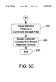
- the system 100 stores the matched portions of the three temporary buffers in the command storage area 118 (see FIGS. 2 and 3).
- step 234 shown in FIG. 5C the system 100 allows the user to select a computer command to be associated with the IR remote control command stored in the command storage area 118.
- the user-selected command is also stored in the command storage area 118.
- the user can assign a "key” or an "action” as the command to be executed by the target computer 105 (see FIG. 2).
- a key may be a single keystroke, mouse event, or the like.
- An action can be any method on any registered control or object in the computer system.
- an action may be a command line, such as "RUN C:WINDOWSMYPROG.BAT.” Such an action would cause the target computer 105 to execute a batch program called MYPROG.
- MYPROG batch program
- Operating systems typically include interface functions that can be readily used by the system 100 to enter commands for execution by the target computer 105.
- Windows 95 Operating System manufactured by Microsoft Corporation
- WIN32API application programmer interface functions
- Some examples of WIN32API functions include “KEYBOARD_EVENT”, “MOUSE_EVENT”, “WINEXEC” ("STRING"), and the like.
- the KEYBOARD_EVENT function allows the user to specify a keystroke, for example, a function key, to simulate user activation of a keyboard (not shown).
- the MOUSE_EVENT function allows the user to simulate a mouse event, such as clicking a mouse button (not shown).
- the WINEXEC (“STRING") function allows the user to enter a string, such as the RUN command described above.
- Other operating systems have similar application program interface functions that can be readily implemented using the system 100.
- the system 100 ends the learn mode operation at an end 236 after the user-selected computer command has been stored in the command storage area 118 in association with the matched portions of data corresponding to the IR remote control button sequence.
- FIG. 6 is a flow chart illustrating the operation of the system 100 in the execute mode.
- the system 100 has stored data corresponding to one or more button sequences from the IR remote control, each stored in the command storage area 118 (see FIGS. 2 and 3), each in association with a user-selected computer command to be executed by the target computer 105.
- the system 100 clears the buffer 126 of all residual data.
- the system 100 captures and samples data transmitted from the IR remote control.
- the error-correction processor 130 detects and corrects errors within the sample data in the manner previously described.
- the data compression processor 132 compresses the error-corrected data.
- step 256 the system 100 compares the error-corrected and compressed data with the stored button sequence data in the command storage area 118.
- the data captured and processed in steps 253 to 255 may be used as a template and compared with the data stored in the command storage area 118.
- the system 100 can be operated with a number of different IR remote controls and permits the user to define multiple commands for each of the IR remote controls. Therefore, the command storage area 118 may have a large number of data entries.
- the system 100 takes a small portion (e.g., three bytes) of each button sequence stored in the command storage area 118 and compares it with the button sequence data captured in steps 253 to 255. If a match is detected between the button sequence data captured in steps 253 to 255 and one or more of the button sequences stored in the command storage area 118, the system 100 compares the entire data entry in the command storage area to determine if a match exists between the stored button sequence data and the captured button sequence data.
- the error correction processor 130 (see FIG. 3) is used in a manner previously described to correct boundary condition errors. However, the error correction processor 130 will not alter the stored data, but will alter the captured button sequence data to match the stored data if such boundary condition errors are detected.
- decision 260 the system 100 determines whether a match has been detected between the captured button sequence data and the stored button sequence data. If a match has been detected, the result of decision 260 is YES and, in step 262, the system 100 causes the target computer 105 (see FIG. 2) to execute the user-selected computer command associated with the IR remote control button sequence. The system 100 ends the execute mode question at 264. Alternatively, the system 100 may operate continuously in the execute mode. In that event, the system 100 returns to step 252 to await the detection of additional transmissions from the IR remote control.
- the system 100 moves to the end 264 without executing a computer command.
- the system 100 may also return operation to step 252 to await the entry of additional transmissions from the IR remote control.
- a conventional appliance such as a television set
- the user typically selects a button a second time if the television set does not respond to the IR remote control when the button is first selected.
- the typical user is conditioned to repeat a remote control button selection a second time if the appliance does not respond to the remote control the first time.
- This user conditioning is useful in situations where high ambient noise results in no match between the captured data and the stored data.
- the system 100 advantageously provides a universal remote control receiver capable of decoding remote control button sequences from virtually any remote control, such as a television remote control, video cassette recorder remote control, or the like. Because the remote controls from different manufacturers produce different codes, the system 100 can be programmed to recognize different user-selected remote button sequences for different remote controls. For example, the remote control button sequence ⁇ 123 ⁇ from a television remote control can cause the target computer 105 to perform one action while the same remote control button sequence (i.e., ⁇ 123 ⁇ ) from a video cassette recorder remote control can cause the target computer to perform the same function or a different function.
- the universal IR receiver of the system 100 provides great flexibility and ease of user programming. The user may readily reprogram button sequences by placing the system 100 in the learn mode and reprogramming remote control button sequences to perform a new user-designated function.
Abstract
Description
00 01 00 00 FF FF FF FE FF 00 00 20 00 00
00 00 00 00.
FF FF FF FF FF.
FF 93 FF
FFh 14h A3h 00h 1Ah
Claims (68)
Priority Applications (1)
| Application Number | Priority Date | Filing Date | Title |
|---|---|---|---|
| US08/884,964 US6097520A (en) | 1997-06-30 | 1997-06-30 | Remote control receiver and method of operation |
Applications Claiming Priority (1)
| Application Number | Priority Date | Filing Date | Title |
|---|---|---|---|
| US08/884,964 US6097520A (en) | 1997-06-30 | 1997-06-30 | Remote control receiver and method of operation |
Publications (1)
| Publication Number | Publication Date |
|---|---|
| US6097520A true US6097520A (en) | 2000-08-01 |
Family
ID=25385832
Family Applications (1)
| Application Number | Title | Priority Date | Filing Date |
|---|---|---|---|
| US08/884,964 Expired - Lifetime US6097520A (en) | 1997-06-30 | 1997-06-30 | Remote control receiver and method of operation |
Country Status (1)
| Country | Link |
|---|---|
| US (1) | US6097520A (en) |
Cited By (59)
| Publication number | Priority date | Publication date | Assignee | Title |
|---|---|---|---|---|
| US6281880B1 (en) * | 1998-06-15 | 2001-08-28 | Vlsi Technology, Inc. | Combining input/output paths for infra-red remote device inputs |
| US6381507B1 (en) * | 1998-07-01 | 2002-04-30 | Sony Corporation | Command pass-through functionality in panel subunit |
| US6498567B1 (en) * | 1999-12-20 | 2002-12-24 | Xerox Corporation | Generic handheld remote control device |
| US20030007649A1 (en) * | 1998-11-17 | 2003-01-09 | Riggs Brett D. | Vehicle remote control interface for controlling multiple electronic devices |
| US20030036395A1 (en) * | 2001-08-14 | 2003-02-20 | Koninklijke Philips Electronics N.V. | Method of and system for providing a programming information for programming a device |
| US6567032B1 (en) | 1999-06-30 | 2003-05-20 | International Business Machines Corp. | Method of directing communication between addressable targets using a generalized pointing device |
| US6570524B1 (en) | 1999-06-30 | 2003-05-27 | International Business Machines Corp. | Method for remote communication with an addressable target using a generalized pointing device |
| US20030170022A1 (en) * | 2002-03-06 | 2003-09-11 | Lucent Technologies Inc. | Method and apparatus for improved jitter tolerance |
| WO2003083588A2 (en) * | 2002-03-22 | 2003-10-09 | Index Systems, Inc. | Method and system for reverse universal remote control feature |
| US20030195969A1 (en) * | 2002-04-04 | 2003-10-16 | Neuman Darren D. | System and method supporting infrared remote control over a network |
| US6761635B2 (en) * | 2000-11-10 | 2004-07-13 | Sony Computer Entertainment Inc. | Remote-control signal receiver |
| US6812881B1 (en) * | 1999-06-30 | 2004-11-02 | International Business Machines Corp. | System for remote communication with an addressable target using a generalized pointing device |
| US20040250153A1 (en) * | 2003-06-03 | 2004-12-09 | Intel Corporation | Data signal redrive with dynamic sampling adjustment |
| US20040250024A1 (en) * | 2003-06-03 | 2004-12-09 | Intel Corporation | Memory channel with hot add/remove |
| US20050044414A1 (en) * | 2003-05-26 | 2005-02-24 | Hideyuki Sawada | Remote control system for controlling installed program |
| DE10337765A1 (en) * | 2003-08-14 | 2005-03-17 | Silvio Voigt | Switching module responding to inputs generated by a remote controller is used to control computer on off switching |
| US6956952B1 (en) * | 1998-11-17 | 2005-10-18 | P.B. Clarke & Assoc. | Remote control interface for replacement vehicle stereos |
| US20050235210A1 (en) * | 2000-11-17 | 2005-10-20 | Streamzap, Inc. | Control of media centric websites by hand-held remote |
| US7020289B1 (en) | 1998-11-17 | 2006-03-28 | P. B. Clarke & Associates | Remote control interface for replacement vehicle stereos |
| US20060197675A1 (en) * | 2005-03-04 | 2006-09-07 | Compal Electronics, Inc. | Remote control interface framework using an infrared module and a method thereof |
| US20060224930A1 (en) * | 2005-03-31 | 2006-10-05 | Ibm Corporation | Systems and methods for event detection |
| US20070076750A1 (en) * | 2005-09-30 | 2007-04-05 | Microsoft Corporation | Device driver interface architecture |
| US20070139569A1 (en) * | 2005-12-02 | 2007-06-21 | Kei Matsubayashi | Device control system, remote control device, and video display device |
| US20070290880A1 (en) * | 2006-06-07 | 2007-12-20 | Sheng-Feng Lin | Method and Apparatus for Universally Decoding Commands of a Remote Controller |
| CN100361515C (en) * | 2004-10-28 | 2008-01-09 | 南京Lg同创彩色显示系统有限责任公司 | Remote control equipment |
| US20080062035A1 (en) * | 2006-09-12 | 2008-03-13 | Kirby Goedde | Ir converter |
| US20080098426A1 (en) * | 2006-10-23 | 2008-04-24 | Candelore Brant L | Decoding multiple remote control code sets |
| US20080098357A1 (en) * | 2006-10-23 | 2008-04-24 | Candelore Brant L | Phantom information commands |
| US7386046B2 (en) * | 2001-02-13 | 2008-06-10 | Realtime Data Llc | Bandwidth sensitive data compression and decompression |
| US20080154806A1 (en) * | 2006-12-22 | 2008-06-26 | Morris Robert P | Methods, systems, and computer program products for a self-automating set of services or devices |
| US20080244637A1 (en) * | 2007-03-28 | 2008-10-02 | Sony Corporation | Obtaining metadata program information during channel changes |
| US7593649B1 (en) * | 2003-09-04 | 2009-09-22 | Digital Networks North America, Inc. | Method and apparatus for wired infrared demodulation |
| US7612685B2 (en) * | 2000-03-15 | 2009-11-03 | Logitech Europe S.A. | Online remote control configuration system |
| US20090278991A1 (en) * | 2006-05-12 | 2009-11-12 | Sony Deutschland Gmbh | Method for interpolating a previous and subsequent image of an input image sequence |
| EP2124209A1 (en) * | 2008-04-29 | 2009-11-25 | Hella KG Hueck & Co. | Method for increasing the range of radio access systems |
| US7714747B2 (en) | 1998-12-11 | 2010-05-11 | Realtime Data Llc | Data compression systems and methods |
| US20100141472A1 (en) * | 2008-12-09 | 2010-06-10 | Mstar Semiconductor, Inc. | Decoding Method and Apparatus for Infrared Remote Control Commands |
| US20100189198A1 (en) * | 2009-01-23 | 2010-07-29 | Conexant Systems, Inc. | Universal Systems and Methods for Determining an Incoming Carrier Frequency and Decoding an Incoming Signal |
| US7777651B2 (en) | 2000-10-03 | 2010-08-17 | Realtime Data Llc | System and method for data feed acceleration and encryption |
| US7796889B1 (en) * | 2005-02-28 | 2010-09-14 | Quartet Technology, Inc | System and method for controlling diverse infrared controlled devices |
| US20110033194A1 (en) * | 2009-08-06 | 2011-02-10 | Sanyo Electric Co., Ltd. | Remote control signal receiving circuit |
| US20110046816A1 (en) * | 2009-08-21 | 2011-02-24 | Circuit Works, Inc. | Methods and systems for providing accessory steering wheel controls |
| US20110046788A1 (en) * | 2009-08-21 | 2011-02-24 | Metra Electronics Corporation | Methods and systems for automatic detection of steering wheel control signals |
| US8026789B2 (en) | 2000-03-15 | 2011-09-27 | Logitech Europe S.A. | State-based remote control system |
| US8090936B2 (en) | 2000-02-03 | 2012-01-03 | Realtime Data, Llc | Systems and methods for accelerated loading of operating systems and application programs |
| US20120105724A1 (en) * | 2010-10-27 | 2012-05-03 | Candelore Brant L | TV Use Simulation |
| WO2012068790A1 (en) * | 2010-11-26 | 2012-05-31 | 赛霸电子(深圳)有限公司 | Method for learning remote control and learning remote control thereof |
| US8275897B2 (en) | 1999-03-11 | 2012-09-25 | Realtime Data, Llc | System and methods for accelerated data storage and retrieval |
| US8285446B2 (en) | 2009-08-21 | 2012-10-09 | Circuit Works, Inc. | Methods and systems for providing accessory steering wheel controls |
| US8504710B2 (en) | 1999-03-11 | 2013-08-06 | Realtime Data Llc | System and methods for accelerated data storage and retrieval |
| US8508401B1 (en) | 2010-08-31 | 2013-08-13 | Logitech Europe S.A. | Delay fixing for command codes in a remote control system |
| US8509400B2 (en) | 2005-04-20 | 2013-08-13 | Logitech Europe S.A. | System and method for adaptive programming of a remote control |
| US8531276B2 (en) | 2000-03-15 | 2013-09-10 | Logitech Europe S.A. | State-based remote control system |
| US20130272715A1 (en) * | 2009-12-21 | 2013-10-17 | Echostar Technologies L.L.C. | Apparatus, systems and methods for compensating infrared noise in an electronic system |
| US8692695B2 (en) | 2000-10-03 | 2014-04-08 | Realtime Data, Llc | Methods for encoding and decoding data |
| US9143546B2 (en) | 2000-10-03 | 2015-09-22 | Realtime Data Llc | System and method for data feed acceleration and encryption |
| US9619114B2 (en) | 2012-06-11 | 2017-04-11 | Automotive Data Solutions, Inc. | Method and system to configure an aftermarket interface module using a graphical user interface |
| US20180240329A1 (en) * | 2017-02-22 | 2018-08-23 | Jay Steinmetz | Control systems with modular configurable devices |
| US20200043323A1 (en) * | 2007-02-09 | 2020-02-06 | Universal Electronics Inc. | Graphical user interface for programming universal remote control devices |
Citations (3)
| Publication number | Priority date | Publication date | Assignee | Title |
|---|---|---|---|---|
| US5436853A (en) * | 1991-07-24 | 1995-07-25 | Nec Corporation | Remote control signal processing circuit for a microcomputer |
| US5900867A (en) * | 1995-07-17 | 1999-05-04 | Gateway 2000, Inc. | Self identifying remote control device having a television receiver for use in a computer |
| US5903259A (en) * | 1997-03-31 | 1999-05-11 | Compaq Computer Corporation | Method and apparatus for mapping remote control buttons onto keyboard stroke combinations |
-
1997
- 1997-06-30 US US08/884,964 patent/US6097520A/en not_active Expired - Lifetime
Patent Citations (3)
| Publication number | Priority date | Publication date | Assignee | Title |
|---|---|---|---|---|
| US5436853A (en) * | 1991-07-24 | 1995-07-25 | Nec Corporation | Remote control signal processing circuit for a microcomputer |
| US5900867A (en) * | 1995-07-17 | 1999-05-04 | Gateway 2000, Inc. | Self identifying remote control device having a television receiver for use in a computer |
| US5903259A (en) * | 1997-03-31 | 1999-05-11 | Compaq Computer Corporation | Method and apparatus for mapping remote control buttons onto keyboard stroke combinations |
Cited By (142)
| Publication number | Priority date | Publication date | Assignee | Title |
|---|---|---|---|---|
| US6281880B1 (en) * | 1998-06-15 | 2001-08-28 | Vlsi Technology, Inc. | Combining input/output paths for infra-red remote device inputs |
| US6381507B1 (en) * | 1998-07-01 | 2002-04-30 | Sony Corporation | Command pass-through functionality in panel subunit |
| US20030007649A1 (en) * | 1998-11-17 | 2003-01-09 | Riggs Brett D. | Vehicle remote control interface for controlling multiple electronic devices |
| US6956952B1 (en) * | 1998-11-17 | 2005-10-18 | P.B. Clarke & Assoc. | Remote control interface for replacement vehicle stereos |
| US20100040237A1 (en) * | 1998-11-17 | 2010-02-18 | Riggs Brett D | Remote control interface for replacement vehicle stereos |
| US7684570B2 (en) * | 1998-11-17 | 2010-03-23 | Aamp Of America | Vehicle remote control interface for controlling multiple electronic devices |
| US7613308B2 (en) | 1998-11-17 | 2009-11-03 | Aamp Of America | Remote control interface for replacement vehicle stereos |
| US20060200364A1 (en) * | 1998-11-17 | 2006-09-07 | Riggs Brett D | Vehicle remote control interface for controlling multiple electronic devices |
| US9165593B2 (en) | 1998-11-17 | 2015-10-20 | Aamp Of Florida, Inc. | Vehicle remote control interface for controlling multiple electronic devices |
| US8284950B2 (en) * | 1998-11-17 | 2012-10-09 | Aamp Of Florida, Inc. | Vehicle remote control interface for controlling multiple electronic devices |
| US8014540B2 (en) | 1998-11-17 | 2011-09-06 | Aamp Of America | Remote control interface for replacement vehicle stereos |
| US20060198535A1 (en) * | 1998-11-17 | 2006-09-07 | Riggs Brett D | Vehicle remote control interface for controlling multiple electronic devices |
| US7020289B1 (en) | 1998-11-17 | 2006-03-28 | P. B. Clarke & Associates | Remote control interface for replacement vehicle stereos |
| US8184825B1 (en) | 1998-11-17 | 2012-05-22 | Aamp Of Florida, Inc. | Vehicle remote control interface for controlling multiple electronic devices |
| US20050249358A1 (en) * | 1998-11-17 | 2005-11-10 | Riggs Brett D | Remote control interface for replacement vehicle stereos |
| US8643513B2 (en) | 1998-12-11 | 2014-02-04 | Realtime Data Llc | Data compression systems and methods |
| US7714747B2 (en) | 1998-12-11 | 2010-05-11 | Realtime Data Llc | Data compression systems and methods |
| US10033405B2 (en) | 1998-12-11 | 2018-07-24 | Realtime Data Llc | Data compression systems and method |
| US8502707B2 (en) | 1998-12-11 | 2013-08-06 | Realtime Data, Llc | Data compression systems and methods |
| US8933825B2 (en) | 1998-12-11 | 2015-01-13 | Realtime Data Llc | Data compression systems and methods |
| US9054728B2 (en) | 1998-12-11 | 2015-06-09 | Realtime Data, Llc | Data compression systems and methods |
| US8717203B2 (en) | 1998-12-11 | 2014-05-06 | Realtime Data, Llc | Data compression systems and methods |
| US8275897B2 (en) | 1999-03-11 | 2012-09-25 | Realtime Data, Llc | System and methods for accelerated data storage and retrieval |
| US8504710B2 (en) | 1999-03-11 | 2013-08-06 | Realtime Data Llc | System and methods for accelerated data storage and retrieval |
| US8756332B2 (en) | 1999-03-11 | 2014-06-17 | Realtime Data Llc | System and methods for accelerated data storage and retrieval |
| US8719438B2 (en) | 1999-03-11 | 2014-05-06 | Realtime Data Llc | System and methods for accelerated data storage and retrieval |
| US10019458B2 (en) | 1999-03-11 | 2018-07-10 | Realtime Data Llc | System and methods for accelerated data storage and retrieval |
| US9116908B2 (en) | 1999-03-11 | 2015-08-25 | Realtime Data Llc | System and methods for accelerated data storage and retrieval |
| US6812881B1 (en) * | 1999-06-30 | 2004-11-02 | International Business Machines Corp. | System for remote communication with an addressable target using a generalized pointing device |
| US6570524B1 (en) | 1999-06-30 | 2003-05-27 | International Business Machines Corp. | Method for remote communication with an addressable target using a generalized pointing device |
| US6567032B1 (en) | 1999-06-30 | 2003-05-20 | International Business Machines Corp. | Method of directing communication between addressable targets using a generalized pointing device |
| US6498567B1 (en) * | 1999-12-20 | 2002-12-24 | Xerox Corporation | Generic handheld remote control device |
| US8112619B2 (en) | 2000-02-03 | 2012-02-07 | Realtime Data Llc | Systems and methods for accelerated loading of operating systems and application programs |
| US8880862B2 (en) | 2000-02-03 | 2014-11-04 | Realtime Data, Llc | Systems and methods for accelerated loading of operating systems and application programs |
| US9792128B2 (en) | 2000-02-03 | 2017-10-17 | Realtime Data, Llc | System and method for electrical boot-device-reset signals |
| US8090936B2 (en) | 2000-02-03 | 2012-01-03 | Realtime Data, Llc | Systems and methods for accelerated loading of operating systems and application programs |
| US7612685B2 (en) * | 2000-03-15 | 2009-11-03 | Logitech Europe S.A. | Online remote control configuration system |
| US8854192B1 (en) | 2000-03-15 | 2014-10-07 | Logitech Europe S.A. | Configuration method for a remote |
| US8653950B2 (en) | 2000-03-15 | 2014-02-18 | Logitech Europe S.A. | State-based remote control system |
| US8674814B2 (en) | 2000-03-15 | 2014-03-18 | Logitech Europe S.A. | State-based remote control system |
| US8330582B2 (en) | 2000-03-15 | 2012-12-11 | Logitech Europe S.A. | Online remote control configuration system |
| US8531276B2 (en) | 2000-03-15 | 2013-09-10 | Logitech Europe S.A. | State-based remote control system |
| US8674815B1 (en) | 2000-03-15 | 2014-03-18 | Logitech Europe S.A. | Configuration method for a remote |
| US8704643B2 (en) | 2000-03-15 | 2014-04-22 | Logitech Europe S.A. | Convenient and easy to use button layout for a remote control |
| US8026789B2 (en) | 2000-03-15 | 2011-09-27 | Logitech Europe S.A. | State-based remote control system |
| US8742905B2 (en) | 2000-03-15 | 2014-06-03 | Logitech Europe S.A. | Easy to use and intuitive user interface for a remote control |
| US8797149B2 (en) | 2000-03-15 | 2014-08-05 | Logitech Europe S.A. | State-based control systems and methods |
| US8692695B2 (en) | 2000-10-03 | 2014-04-08 | Realtime Data, Llc | Methods for encoding and decoding data |
| US9143546B2 (en) | 2000-10-03 | 2015-09-22 | Realtime Data Llc | System and method for data feed acceleration and encryption |
| US9141992B2 (en) | 2000-10-03 | 2015-09-22 | Realtime Data Llc | Data feed acceleration |
| US7777651B2 (en) | 2000-10-03 | 2010-08-17 | Realtime Data Llc | System and method for data feed acceleration and encryption |
| US9859919B2 (en) | 2000-10-03 | 2018-01-02 | Realtime Data Llc | System and method for data compression |
| US10419021B2 (en) | 2000-10-03 | 2019-09-17 | Realtime Data, Llc | Systems and methods of data compression |
| US8717204B2 (en) | 2000-10-03 | 2014-05-06 | Realtime Data Llc | Methods for encoding and decoding data |
| US10284225B2 (en) | 2000-10-03 | 2019-05-07 | Realtime Data, Llc | Systems and methods for data compression |
| US9967368B2 (en) | 2000-10-03 | 2018-05-08 | Realtime Data Llc | Systems and methods for data block decompression |
| US9667751B2 (en) | 2000-10-03 | 2017-05-30 | Realtime Data, Llc | Data feed acceleration |
| US8723701B2 (en) | 2000-10-03 | 2014-05-13 | Realtime Data Llc | Methods for encoding and decoding data |
| US8742958B2 (en) | 2000-10-03 | 2014-06-03 | Realtime Data Llc | Methods for encoding and decoding data |
| US6761635B2 (en) * | 2000-11-10 | 2004-07-13 | Sony Computer Entertainment Inc. | Remote-control signal receiver |
| US8418062B2 (en) | 2000-11-17 | 2013-04-09 | Jonah Peskin | Control of media centric websites by hand-held remote |
| US20160371055A1 (en) * | 2000-11-17 | 2016-12-22 | Streamzap, Inc. | Embedded audio/video playout program frequently requests keyboard focus |
| US6976216B1 (en) | 2000-11-17 | 2005-12-13 | Streamzap, Inc. | Computer system with remote key press events directed to a first application program and local key press events directed to a second application program |
| US20050235210A1 (en) * | 2000-11-17 | 2005-10-20 | Streamzap, Inc. | Control of media centric websites by hand-held remote |
| US9086786B2 (en) * | 2000-11-17 | 2015-07-21 | Streamzap, Inc. | Web site program directs control of a media player |
| US9864578B2 (en) * | 2000-11-17 | 2018-01-09 | Streamzap, Inc. | Techniques for distinguishing respective user input commands as directed to media player and program for displaying web pages |
| US20140189511A1 (en) * | 2000-11-17 | 2014-07-03 | Streamzap, Inc. | Web site program directs control of a media player |
| US8934535B2 (en) | 2001-02-13 | 2015-01-13 | Realtime Data Llc | Systems and methods for video and audio data storage and distribution |
| US8054879B2 (en) | 2001-02-13 | 2011-11-08 | Realtime Data Llc | Bandwidth sensitive data compression and decompression |
| US8553759B2 (en) | 2001-02-13 | 2013-10-08 | Realtime Data, Llc | Bandwidth sensitive data compression and decompression |
| US10212417B2 (en) | 2001-02-13 | 2019-02-19 | Realtime Adaptive Streaming Llc | Asymmetric data decompression systems |
| US9762907B2 (en) | 2001-02-13 | 2017-09-12 | Realtime Adaptive Streaming, LLC | System and methods for video and audio data distribution |
| US8867610B2 (en) | 2001-02-13 | 2014-10-21 | Realtime Data Llc | System and methods for video and audio data distribution |
| US9769477B2 (en) | 2001-02-13 | 2017-09-19 | Realtime Adaptive Streaming, LLC | Video data compression systems |
| US8929442B2 (en) | 2001-02-13 | 2015-01-06 | Realtime Data, Llc | System and methods for video and audio data distribution |
| US8073047B2 (en) | 2001-02-13 | 2011-12-06 | Realtime Data, Llc | Bandwidth sensitive data compression and decompression |
| US7386046B2 (en) * | 2001-02-13 | 2008-06-10 | Realtime Data Llc | Bandwidth sensitive data compression and decompression |
| US20030036395A1 (en) * | 2001-08-14 | 2003-02-20 | Koninklijke Philips Electronics N.V. | Method of and system for providing a programming information for programming a device |
| US20030170022A1 (en) * | 2002-03-06 | 2003-09-11 | Lucent Technologies Inc. | Method and apparatus for improved jitter tolerance |
| US8639127B2 (en) * | 2002-03-06 | 2014-01-28 | Alcatel Lucent | Method and apparatus for improved jitter tolerance |
| WO2003083588A2 (en) * | 2002-03-22 | 2003-10-09 | Index Systems, Inc. | Method and system for reverse universal remote control feature |
| WO2003083588A3 (en) * | 2002-03-22 | 2004-02-19 | Index Systems Inc | Method and system for reverse universal remote control feature |
| US20140233909A1 (en) * | 2002-04-04 | 2014-08-21 | Broadcom Corporation | System and method supporting infrared remote control over a network |
| US20030195969A1 (en) * | 2002-04-04 | 2003-10-16 | Neuman Darren D. | System and method supporting infrared remote control over a network |
| US9338496B2 (en) * | 2002-04-04 | 2016-05-10 | Broadcom Corporation | System and method supporting infrared remote control over a network |
| US20050044414A1 (en) * | 2003-05-26 | 2005-02-24 | Hideyuki Sawada | Remote control system for controlling installed program |
| US7292157B2 (en) * | 2003-05-26 | 2007-11-06 | Onkyo Corporation | Remote control system for controlling installed program |
| US20040250153A1 (en) * | 2003-06-03 | 2004-12-09 | Intel Corporation | Data signal redrive with dynamic sampling adjustment |
| US20040250024A1 (en) * | 2003-06-03 | 2004-12-09 | Intel Corporation | Memory channel with hot add/remove |
| US7194581B2 (en) * | 2003-06-03 | 2007-03-20 | Intel Corporation | Memory channel with hot add/remove |
| DE10337765A1 (en) * | 2003-08-14 | 2005-03-17 | Silvio Voigt | Switching module responding to inputs generated by a remote controller is used to control computer on off switching |
| US7593649B1 (en) * | 2003-09-04 | 2009-09-22 | Digital Networks North America, Inc. | Method and apparatus for wired infrared demodulation |
| CN100361515C (en) * | 2004-10-28 | 2008-01-09 | 南京Lg同创彩色显示系统有限责任公司 | Remote control equipment |
| US7796889B1 (en) * | 2005-02-28 | 2010-09-14 | Quartet Technology, Inc | System and method for controlling diverse infrared controlled devices |
| US20060197675A1 (en) * | 2005-03-04 | 2006-09-07 | Compal Electronics, Inc. | Remote control interface framework using an infrared module and a method thereof |
| US20060224930A1 (en) * | 2005-03-31 | 2006-10-05 | Ibm Corporation | Systems and methods for event detection |
| US7475135B2 (en) * | 2005-03-31 | 2009-01-06 | International Business Machines Corporation | Systems and methods for event detection |
| US20080276131A1 (en) * | 2005-03-31 | 2008-11-06 | International Business Machines Corporation | Systems and methods for event detection |
| US8509400B2 (en) | 2005-04-20 | 2013-08-13 | Logitech Europe S.A. | System and method for adaptive programming of a remote control |
| US9207652B2 (en) | 2005-04-20 | 2015-12-08 | Logitech Europe S.A. | System and method for adaptive programming of a remote control |
| US20070076750A1 (en) * | 2005-09-30 | 2007-04-05 | Microsoft Corporation | Device driver interface architecture |
| US20070139569A1 (en) * | 2005-12-02 | 2007-06-21 | Kei Matsubayashi | Device control system, remote control device, and video display device |
| US8340186B2 (en) * | 2006-05-12 | 2012-12-25 | Sony Deutschland Gmbh | Method for interpolating a previous and subsequent image of an input image sequence |
| US20090278991A1 (en) * | 2006-05-12 | 2009-11-12 | Sony Deutschland Gmbh | Method for interpolating a previous and subsequent image of an input image sequence |
| US20070290880A1 (en) * | 2006-06-07 | 2007-12-20 | Sheng-Feng Lin | Method and Apparatus for Universally Decoding Commands of a Remote Controller |
| US8072315B2 (en) * | 2006-06-07 | 2011-12-06 | Mstar Semiconductor, Inc. | Method and apparatus for universally decoding commands of a remote controller |
| US20080062035A1 (en) * | 2006-09-12 | 2008-03-13 | Kirby Goedde | Ir converter |
| US8629942B2 (en) | 2006-10-23 | 2014-01-14 | Sony Corporation | Decoding multiple remote control code sets |
| US8077263B2 (en) | 2006-10-23 | 2011-12-13 | Sony Corporation | Decoding multiple remote control code sets |
| US20080098426A1 (en) * | 2006-10-23 | 2008-04-24 | Candelore Brant L | Decoding multiple remote control code sets |
| US20080098357A1 (en) * | 2006-10-23 | 2008-04-24 | Candelore Brant L | Phantom information commands |
| US20080154806A1 (en) * | 2006-12-22 | 2008-06-26 | Morris Robert P | Methods, systems, and computer program products for a self-automating set of services or devices |
| US11551546B2 (en) * | 2007-02-09 | 2023-01-10 | Universal Electronics Inc. | Graphical user interface for programming universal remote control devices |
| US20200043323A1 (en) * | 2007-02-09 | 2020-02-06 | Universal Electronics Inc. | Graphical user interface for programming universal remote control devices |
| US11790769B2 (en) | 2007-02-09 | 2023-10-17 | Universal Electronics Inc. | Graphical user interface for programming universal remote control devices |
| US20080244637A1 (en) * | 2007-03-28 | 2008-10-02 | Sony Corporation | Obtaining metadata program information during channel changes |
| US8621498B2 (en) | 2007-03-28 | 2013-12-31 | Sony Corporation | Obtaining metadata program information during channel changes |
| US8438589B2 (en) | 2007-03-28 | 2013-05-07 | Sony Corporation | Obtaining metadata program information during channel changes |
| EP2124209A1 (en) * | 2008-04-29 | 2009-11-25 | Hella KG Hueck & Co. | Method for increasing the range of radio access systems |
| US8295407B2 (en) * | 2008-12-09 | 2012-10-23 | Mstar Semiconductor, Inc. | Decoding method and apparatus for infrared remote control commands |
| US20100141472A1 (en) * | 2008-12-09 | 2010-06-10 | Mstar Semiconductor, Inc. | Decoding Method and Apparatus for Infrared Remote Control Commands |
| US20100189198A1 (en) * | 2009-01-23 | 2010-07-29 | Conexant Systems, Inc. | Universal Systems and Methods for Determining an Incoming Carrier Frequency and Decoding an Incoming Signal |
| US9025959B2 (en) | 2009-01-23 | 2015-05-05 | Conexant Systems, Inc. | Universal systems and methods for determining an incoming carrier frequency and decoding an incoming signal |
| US8213809B2 (en) | 2009-01-23 | 2012-07-03 | Conexant Systems, Inc. | Universal systems and methods for determining an incoming carrier frequency and decoding an incoming signal |
| US8670677B2 (en) * | 2009-08-06 | 2014-03-11 | Sanyo Semiconductor Co., Ltd. | Remote control signal receiving circuit |
| US20110033194A1 (en) * | 2009-08-06 | 2011-02-10 | Sanyo Electric Co., Ltd. | Remote control signal receiving circuit |
| US8014920B2 (en) | 2009-08-21 | 2011-09-06 | Metra Electronics Corporation | Methods and systems for providing accessory steering wheel controls |
| US8214105B2 (en) | 2009-08-21 | 2012-07-03 | Metra Electronics Corporation | Methods and systems for automatic detection of steering wheel control signals |
| US8285446B2 (en) | 2009-08-21 | 2012-10-09 | Circuit Works, Inc. | Methods and systems for providing accessory steering wheel controls |
| US8527147B2 (en) | 2009-08-21 | 2013-09-03 | Circuit Works, Inc. | Methods and systems for automatic detection of vehicle configuration |
| US20110046788A1 (en) * | 2009-08-21 | 2011-02-24 | Metra Electronics Corporation | Methods and systems for automatic detection of steering wheel control signals |
| US20110046816A1 (en) * | 2009-08-21 | 2011-02-24 | Circuit Works, Inc. | Methods and systems for providing accessory steering wheel controls |
| US8825289B2 (en) | 2009-08-21 | 2014-09-02 | Metra Electronics Corporation | Method and apparatus for integration of factory and aftermarket vehicle components |
| US9020354B2 (en) * | 2009-12-21 | 2015-04-28 | Echostar Technologies L.L.C. | Apparatus, systems and methods for compensating infrared noise in an electronic system |
| US20130272715A1 (en) * | 2009-12-21 | 2013-10-17 | Echostar Technologies L.L.C. | Apparatus, systems and methods for compensating infrared noise in an electronic system |
| US8508401B1 (en) | 2010-08-31 | 2013-08-13 | Logitech Europe S.A. | Delay fixing for command codes in a remote control system |
| US8488067B2 (en) * | 2010-10-27 | 2013-07-16 | Sony Corporation | TV use simulation |
| US20120105724A1 (en) * | 2010-10-27 | 2012-05-03 | Candelore Brant L | TV Use Simulation |
| WO2012068790A1 (en) * | 2010-11-26 | 2012-05-31 | 赛霸电子(深圳)有限公司 | Method for learning remote control and learning remote control thereof |
| US9619114B2 (en) | 2012-06-11 | 2017-04-11 | Automotive Data Solutions, Inc. | Method and system to configure an aftermarket interface module using a graphical user interface |
| US10242562B2 (en) * | 2017-02-22 | 2019-03-26 | Thames Technology Holdings, Inc. | Control systems with modular configurable devices |
| US20180240329A1 (en) * | 2017-02-22 | 2018-08-23 | Jay Steinmetz | Control systems with modular configurable devices |
Similar Documents
| Publication | Publication Date | Title |
|---|---|---|
| US6097520A (en) | Remote control receiver and method of operation | |
| US6130625A (en) | Universal remote control with incoming signal identification | |
| US6097309A (en) | Remote control learning system and method using signal envelope pattern recognition | |
| KR100705307B1 (en) | Automatic configuration mechanism for universal remote | |
| KR940003445B1 (en) | Reconfigurable remote control | |
| US10720048B2 (en) | Infrared remote control learning method and device | |
| US5579496A (en) | Method and apparatus for processing control instructions received from multiple sources connected to a communication bus | |
| US20100039282A1 (en) | Universal Remote Control Programming | |
| JP3704148B2 (en) | Method and apparatus for remote operation | |
| US4377006A (en) | IR Remote control system | |
| US20120219298A1 (en) | Remote control system and method having reduced vulnerability to noise | |
| CN101123035A (en) | Remote control receiving device and method based on infrared | |
| US9235986B2 (en) | Universal remote control programming | |
| US5657005A (en) | Operation of a system using a remote control | |
| US5077552A (en) | Interface for coupling audio and video equipment to computer | |
| US5185766A (en) | Apparatus and method for decoding biphase-coded data | |
| EP0448152B1 (en) | Remote control system, and transmitter and receiver for such a system | |
| KR910007815B1 (en) | Decoding method of biphase encoding data | |
| GB2305276A (en) | Learning remote control IR codes | |
| CN1172314A (en) | Multifunctional intelligent infrared telecontroller | |
| KR960015388B1 (en) | General-function remote control transmitter and controlling method for it | |
| CN113763951B (en) | Intelligent watch capable of controlling intelligent home through voice and infrared | |
| JPS62195997A (en) | Remote controller | |
| JPH0416025A (en) | Double sign device of two phase coaded data and method | |
| KR100188915B1 (en) | Macro control method of appliances using home-bus |
Legal Events
| Date | Code | Title | Description |
|---|---|---|---|
| AS | Assignment |
Owner name: MICROSOFT CORPORATION, WASHINGTON Free format text: ASSIGNMENT OF ASSIGNORS INTEREST;ASSIGNOR:KADNIER, GRIFFITH W.;REEL/FRAME:008661/0204 Effective date: 19970630 |
|
| STCF | Information on status: patent grant |
Free format text: PATENTED CASE |
|
| FEPP | Fee payment procedure |
Free format text: PAYOR NUMBER ASSIGNED (ORIGINAL EVENT CODE: ASPN); ENTITY STATUS OF PATENT OWNER: LARGE ENTITY |
|
| CC | Certificate of correction | ||
| FPAY | Fee payment |
Year of fee payment: 4 |
|
| FPAY | Fee payment |
Year of fee payment: 8 |
|
| FPAY | Fee payment |
Year of fee payment: 12 |
|
| AS | Assignment |
Owner name: MICROSOFT TECHNOLOGY LICENSING, LLC, WASHINGTON Free format text: ASSIGNMENT OF ASSIGNORS INTEREST;ASSIGNOR:MICROSOFT CORPORATION;REEL/FRAME:034541/0001 Effective date: 20141014 |