US6091993A - Methods and apparatus for an electrode balloon - Google Patents
Methods and apparatus for an electrode balloon Download PDFInfo
- Publication number
- US6091993A US6091993A US09/026,349 US2634998A US6091993A US 6091993 A US6091993 A US 6091993A US 2634998 A US2634998 A US 2634998A US 6091993 A US6091993 A US 6091993A
- Authority
- US
- United States
- Prior art keywords
- electrosurgical electrode
- membrane
- balloon
- edge
- circumferential
- Prior art date
- Legal status (The legal status is an assumption and is not a legal conclusion. Google has not performed a legal analysis and makes no representation as to the accuracy of the status listed.)
- Expired - Fee Related
Links
Images


Classifications
-
- A—HUMAN NECESSITIES
- A61—MEDICAL OR VETERINARY SCIENCE; HYGIENE
- A61B—DIAGNOSIS; SURGERY; IDENTIFICATION
- A61B18/00—Surgical instruments, devices or methods for transferring non-mechanical forms of energy to or from the body
- A61B18/04—Surgical instruments, devices or methods for transferring non-mechanical forms of energy to or from the body by heating
- A61B18/12—Surgical instruments, devices or methods for transferring non-mechanical forms of energy to or from the body by heating by passing a current through the tissue to be heated, e.g. high-frequency current
- A61B18/14—Probes or electrodes therefor
- A61B18/1485—Probes or electrodes therefor having a short rigid shaft for accessing the inner body through natural openings
-
- A—HUMAN NECESSITIES
- A61—MEDICAL OR VETERINARY SCIENCE; HYGIENE
- A61B—DIAGNOSIS; SURGERY; IDENTIFICATION
- A61B18/00—Surgical instruments, devices or methods for transferring non-mechanical forms of energy to or from the body
- A61B18/04—Surgical instruments, devices or methods for transferring non-mechanical forms of energy to or from the body by heating
- A61B18/12—Surgical instruments, devices or methods for transferring non-mechanical forms of energy to or from the body by heating by passing a current through the tissue to be heated, e.g. high-frequency current
- A61B18/14—Probes or electrodes therefor
- A61B18/16—Indifferent or passive electrodes for grounding
-
- A—HUMAN NECESSITIES
- A61—MEDICAL OR VETERINARY SCIENCE; HYGIENE
- A61B—DIAGNOSIS; SURGERY; IDENTIFICATION
- A61B18/00—Surgical instruments, devices or methods for transferring non-mechanical forms of energy to or from the body
- A61B2018/00053—Mechanical features of the instrument of device
- A61B2018/00214—Expandable means emitting energy, e.g. by elements carried thereon
- A61B2018/0022—Balloons
- A61B2018/00238—Balloons porous
-
- A—HUMAN NECESSITIES
- A61—MEDICAL OR VETERINARY SCIENCE; HYGIENE
- A61B—DIAGNOSIS; SURGERY; IDENTIFICATION
- A61B18/00—Surgical instruments, devices or methods for transferring non-mechanical forms of energy to or from the body
- A61B2018/00053—Mechanical features of the instrument of device
- A61B2018/00214—Expandable means emitting energy, e.g. by elements carried thereon
- A61B2018/0022—Balloons
- A61B2018/0025—Multiple balloons
- A61B2018/00255—Multiple balloons arranged one inside another
-
- A—HUMAN NECESSITIES
- A61—MEDICAL OR VETERINARY SCIENCE; HYGIENE
- A61B—DIAGNOSIS; SURGERY; IDENTIFICATION
- A61B18/00—Surgical instruments, devices or methods for transferring non-mechanical forms of energy to or from the body
- A61B18/04—Surgical instruments, devices or methods for transferring non-mechanical forms of energy to or from the body by heating
- A61B18/12—Surgical instruments, devices or methods for transferring non-mechanical forms of energy to or from the body by heating by passing a current through the tissue to be heated, e.g. high-frequency current
- A61B18/14—Probes or electrodes therefor
- A61B2018/1467—Probes or electrodes therefor using more than two electrodes on a single probe
-
- A—HUMAN NECESSITIES
- A61—MEDICAL OR VETERINARY SCIENCE; HYGIENE
- A61B—DIAGNOSIS; SURGERY; IDENTIFICATION
- A61B2218/00—Details of surgical instruments, devices or methods for transferring non-mechanical forms of energy to or from the body
- A61B2218/001—Details of surgical instruments, devices or methods for transferring non-mechanical forms of energy to or from the body having means for irrigation and/or aspiration of substances to and/or from the surgical site
- A61B2218/002—Irrigation
Definitions
- This relates to a flexible support for a thin electrically conductive electrosurgical electrode. More particularly, a circumferential frame shaped to capture an edge of the electrosurgical electrode.
- U.S. Pat. No. 5,443,470 has a regulated heating device with a balloon having electrodes for delivery of radio frequency energy to the endometrium.
- a method of making a flexible support for a thin electrically conductive electrosurgical electrode may have steps.
- Providing a mold cavity to receive and shape the flexible support is a preferred step.
- the mold most preferably has an unpolished surface finish to enhance release properties during removal of the flexible support.
- a step could include filling the mold cavity with a thermosetting polymer.
- An under cut on the circumferential frame most preferably is for substantially holding and enclosing the edge of the electrosurgical electrode.
- a membrane is desired to be integral with the one or more circumferential frames for extending from each circumferential frame and coextensive with each circumferential frame.
- the new design consists of a method for molding the balloon with specific molded locations for the electrosurgical electrodes. These molded locations include an under cut to capture the edge of the electrosurgical electrode.
- the molded balloon includes a membrane between the electrode locations. The membrane preferably has a thinner wall section. This difference in wall section allows the balloon to expand within the uterus more uniformly without dislocating the electrosurgical electrodes from the balloon surface. Thus the uterine space is filled more uniformly for distributing the electrosurgical electrodes and subsequently radio frequency energy to more uniformly within the uterine space.
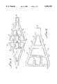
- FIG. 2 is a partial enlarged side view in cross section taken along line 2--2 as shown in FIG. 1 with particular emphasis on the relationship of the electrosurgical electrode and the balloon in the area of one circumferential frame.
- FIG. 5 is a schematic representation of the mold and its core shown as a side view in cross section to illustrate the way in which a balloon is formed by molding.
- FIG. 6 is an enlarged partial detail of the mold cavity used to form one under cut, window opening, circumferential frame and the membrane thereabout.
- Uterine balloon therapy to treat dysfunctional uterine bleeding with radio frequency electrodes is described in the patents referenced in the background of this disclosure.
- the disclosed balloon and method for molding has specific molded locations to receive electrosurgical electrodes. These molded locations capture each electrode to the exterior of the balloon. Between the molded locations containing the electrodes the balloon has a flexible wall section allowing expansion within the uterus without dislocating the electrosurgical electrodes from the balloon. Thus the uterus is filled uniformly for distributing the electrosurgical electrodes and applying radio frequency energy to the uterine walls.
- One or more circumferential frames 15 form the molded locations for electrosurgical electrode 11 support and containment. Each circumferential frame 15 is shaped to capture the edge 12 of one of the electrosurgical electrodes 11 on the support 10.
- An under cut 16, best seen in FIG. 2, provided beneath each circumferential frame 15 locates each respective electrosurgical electrode 11 for substantially holding and enclosing the edge 12 of the electrosurgical electrode 11.
- a membrane 17 integral with the one or more circumferential frames 15 extends there beneath and therebetween to form a balloon wall 18 that is about 0.254 mm thick. The membrane 17 thus extends from each circumferential frame 15 and is coextensive with each circumferential frame 15 forming a continuous inflatable bladder 19, as shown in FIGS. 1 and 4.
- the membrane 17 has a thinness sufficient to allow expansion of the membrane 17 in deference to each of the one or more circumferential frames 15.
- the one or more circumferential frames 15, the under cut 16 and the membrane 17 are molded into an integral flexible support 10.
- the membrane 17 is integral with the one or more circumferential frames 15, the membrane 17 resides within the circumferential frame 15 and forms the exterior surface 21 of balloon 19.
- the membrane 17 is thin so as to expand upon inflation of the inflatable balloon 19 before and/or to a greater extent than each of the one or more circumferential frames 15.
- the membrane 17 is continuous except at the port 22 and at each of the one or more circumferential frames 15 there can be a hole 24 to pass a conductor 25 to couple the electrosurgical electrode 11 held therewithin to a source of electrosurgical energy (not shown) during use in ablating the inside of the uterus.
- the electrosurgical electrodes 11 when made of electrically conductive polymeric film should have less extensibility than the membrane 17 of the inflatable balloon 19.
- each of the one or more circumferential frames 15 resist change in shape during inflation of the inflatable balloon 19.
- the extensibility of each of the one or more circumferential frames 15 is desirably about that of the conductive film edge 12 of the electrosurgical electrodes 11. Consequently, each of the one or more circumferential frames 15 reinforces the inflatable balloon 19 so that expansion during inflation is primarily in the membrane 17 between the one or more circumferential frames 15 and not in the portions of the membrane 17 within each of the one or more circumferential frames 15.
- the membrane 17 is molded in the mold cavity 30 with a thinness sufficient to allow expansion in deference to the one or more circumferential frames 15.
- the one or more circumferential frames 15, the under cut 16 and the membrane 17 could in a step of the method be molded into inflatable silicon balloon 19.
- the steps of folding the flexible support 10 and sealing abutting sides 31 in FIG. 3 in an alternate configuration thereof to form inflatable balloon 19 can be performed if the mold cavity 30 is of a flat preform 32.
- the step of inserting a core 33 into the mold cavity 30 to form balloon 19 during the step of filling may be an alternate step, as depicted in FIG. 5.
Abstract
Description
Claims (11)
Priority Applications (7)
| Application Number | Priority Date | Filing Date | Title |
|---|---|---|---|
| US09/026,349 US6091993A (en) | 1998-02-19 | 1998-02-19 | Methods and apparatus for an electrode balloon |
| EP99934237A EP1056406A1 (en) | 1998-02-19 | 1999-02-17 | Methods and apparatus for an electrode balloon |
| CA002318043A CA2318043A1 (en) | 1998-02-19 | 1999-02-17 | Methods and apparatus for an electrode balloon |
| PCT/US1999/003334 WO1999042043A1 (en) | 1998-02-19 | 1999-02-17 | Methods and apparatus for an electrode balloon |
| JP2000532064A JP2002503511A (en) | 1998-02-19 | 1999-02-17 | Method and apparatus for electrode balloon |
| AU32958/99A AU743236B2 (en) | 1998-02-19 | 1999-02-17 | Methods and apparatus for an electrode balloon |
| US09/565,995 US6468462B1 (en) | 1998-02-19 | 2000-05-06 | Method for making an electrode balloon |
Applications Claiming Priority (1)
| Application Number | Priority Date | Filing Date | Title |
|---|---|---|---|
| US09/026,349 US6091993A (en) | 1998-02-19 | 1998-02-19 | Methods and apparatus for an electrode balloon |
Related Child Applications (1)
| Application Number | Title | Priority Date | Filing Date |
|---|---|---|---|
| US09/565,995 Division US6468462B1 (en) | 1998-02-19 | 2000-05-06 | Method for making an electrode balloon |
Publications (1)
| Publication Number | Publication Date |
|---|---|
| US6091993A true US6091993A (en) | 2000-07-18 |
Family
ID=21831315
Family Applications (2)
| Application Number | Title | Priority Date | Filing Date |
|---|---|---|---|
| US09/026,349 Expired - Fee Related US6091993A (en) | 1998-02-19 | 1998-02-19 | Methods and apparatus for an electrode balloon |
| US09/565,995 Expired - Lifetime US6468462B1 (en) | 1998-02-19 | 2000-05-06 | Method for making an electrode balloon |
Family Applications After (1)
| Application Number | Title | Priority Date | Filing Date |
|---|---|---|---|
| US09/565,995 Expired - Lifetime US6468462B1 (en) | 1998-02-19 | 2000-05-06 | Method for making an electrode balloon |
Country Status (6)
| Country | Link |
|---|---|
| US (2) | US6091993A (en) |
| EP (1) | EP1056406A1 (en) |
| JP (1) | JP2002503511A (en) |
| AU (1) | AU743236B2 (en) |
| CA (1) | CA2318043A1 (en) |
| WO (1) | WO1999042043A1 (en) |
Cited By (53)
| Publication number | Priority date | Publication date | Assignee | Title |
|---|---|---|---|---|
| WO2002019934A1 (en) * | 2000-09-08 | 2002-03-14 | Atrionx, Inc. | Medical device with sensor cooperating with expandable member |
| WO2002078557A1 (en) * | 2001-03-30 | 2002-10-10 | Ethicon Endo-Surgery, Inc. | Endoscopic ablation system with improved electrode geometry |
| US6468462B1 (en) | 1998-02-19 | 2002-10-22 | Ams Research Corporation | Method for making an electrode balloon |
| US20020177847A1 (en) * | 2001-03-30 | 2002-11-28 | Long Gary L. | Endoscopic ablation system with flexible coupling |
| US6547788B1 (en) | 1997-07-08 | 2003-04-15 | Atrionx, Inc. | Medical device with sensor cooperating with expandable member |
| US6572639B1 (en) * | 1998-07-31 | 2003-06-03 | Surx, Inc. | Interspersed heating/cooling to shrink tissues for incontinence |
| US20030158550A1 (en) * | 1999-11-16 | 2003-08-21 | Ganz Robert A. | Method of treating abnormal tissue in the human esophagus |
| US20030181905A1 (en) * | 2002-03-25 | 2003-09-25 | Long Gary L. | Endoscopic ablation system with a distally mounted image sensor |
| US20030181900A1 (en) * | 2002-03-25 | 2003-09-25 | Long Gary L. | Endoscopic ablation system with a plurality of electrodes |
| US20030216727A1 (en) * | 2001-03-30 | 2003-11-20 | Long Gary L. | Medical device with improved wall construction |
| US6776779B1 (en) * | 1998-07-31 | 2004-08-17 | Solarant Medical, Inc. | Static devices and methods to shrink tissues for incontinence |
| US20040215235A1 (en) * | 1999-11-16 | 2004-10-28 | Barrx, Inc. | Methods and systems for determining physiologic characteristics for treatment of the esophagus |
| US20050070888A1 (en) * | 2004-10-29 | 2005-03-31 | Boston Scientific Corporation | Medical device systems and methods |
| US20050127561A1 (en) * | 2003-12-16 | 2005-06-16 | Scimed Life Systems, Inc. | Method of making expandable-collapsible bodies by temperature gradient expansion molding |
| US20050171524A1 (en) * | 2004-01-09 | 2005-08-04 | Barrx, Inc. | Devices and methods for treatment of luminal tissue |
| US20050283939A1 (en) * | 2004-06-25 | 2005-12-29 | The Hoover Company | Handle assembly for a cleaning apparatus |
| US20060167533A1 (en) * | 2005-01-21 | 2006-07-27 | Solarant Medical, Inc. | Endo-pelvic fascia penetrating heating systems and methods for incontinence treatment |
| US7232438B2 (en) | 2004-07-09 | 2007-06-19 | Ethicon Endo-Surgery, Inc. | Ablation device with clear probe |
| US20070288001A1 (en) * | 2006-06-12 | 2007-12-13 | Pankaj Patel | Endoscopically introducible expandable cautery device |
| US20080172117A1 (en) * | 2007-01-12 | 2008-07-17 | Skubitz Sean P | Expandable systems for medical electrical stimulation |
| US20080281317A1 (en) * | 2007-05-10 | 2008-11-13 | Fred Gobel | Endometrial Ablation catheter |
| US20110112523A1 (en) * | 2009-11-11 | 2011-05-12 | Minerva Surgical, Inc. | Systems, methods and devices for endometrial ablation utilizing radio frequency |
| US20110118719A1 (en) * | 2009-11-13 | 2011-05-19 | Minerva Surgical, Inc. | Systems and methods for endometrial ablation |
| US20110118718A1 (en) * | 2009-11-13 | 2011-05-19 | Minerva Surgical, Inc. | Methods and systems for endometrial ablation utilizing radio frequency |
| US7959627B2 (en) | 2005-11-23 | 2011-06-14 | Barrx Medical, Inc. | Precision ablating device |
| US7997278B2 (en) | 2005-11-23 | 2011-08-16 | Barrx Medical, Inc. | Precision ablating method |
| US8012149B2 (en) | 1999-11-16 | 2011-09-06 | Barrx Medical, Inc. | Methods and systems for determining physiologic characteristics for treatment of the esophagus |
| US20120010611A1 (en) * | 2010-07-09 | 2012-01-12 | Intuitive Surgical Operations, Inc. | Electrosurgical tool cover |
| US8251992B2 (en) | 2007-07-06 | 2012-08-28 | Tyco Healthcare Group Lp | Method and apparatus for gastrointestinal tract ablation to achieve loss of persistent and/or recurrent excess body weight following a weight-loss operation |
| US20120239028A1 (en) * | 2011-03-18 | 2012-09-20 | Wallace Michael P | Selectively expandable operative element support structure and methods of use |
| US8273012B2 (en) | 2007-07-30 | 2012-09-25 | Tyco Healthcare Group, Lp | Cleaning device and methods |
| US8439908B2 (en) | 2007-07-06 | 2013-05-14 | Covidien Lp | Ablation in the gastrointestinal tract to achieve hemostasis and eradicate lesions with a propensity for bleeding |
| US8641711B2 (en) | 2007-05-04 | 2014-02-04 | Covidien Lp | Method and apparatus for gastrointestinal tract ablation for treatment of obesity |
| US8646460B2 (en) | 2007-07-30 | 2014-02-11 | Covidien Lp | Cleaning device and methods |
| US8702694B2 (en) | 2005-11-23 | 2014-04-22 | Covidien Lp | Auto-aligning ablating device and method of use |
| US8784338B2 (en) | 2007-06-22 | 2014-07-22 | Covidien Lp | Electrical means to normalize ablational energy transmission to a luminal tissue surface of varying size |
| WO2014149925A1 (en) * | 2013-03-15 | 2014-09-25 | Medtronic Ablation Frontiers Llc | Contact specific rf therapy balloon |
| US8909316B2 (en) | 2011-05-18 | 2014-12-09 | St. Jude Medical, Cardiology Division, Inc. | Apparatus and method of assessing transvascular denervation |
| US20150057657A1 (en) * | 2013-08-22 | 2015-02-26 | Boston Scientific Scimed, Inc. | Medical balloon having patterned recessed wall profile |
| US9089351B2 (en) | 2010-02-12 | 2015-07-28 | Intuitive Surgical Operations, Inc. | Sheath for surgical instrument |
| US20150223876A1 (en) * | 2012-09-19 | 2015-08-13 | Hologic, Inc. | Ablation device using bipolar steam generation |
| US20150265936A1 (en) * | 2014-03-21 | 2015-09-24 | Dan Canobbio | Multipurpose recreational toy for converting a balloon to an item used in sports |
| US20170231681A1 (en) * | 2008-10-21 | 2017-08-17 | Hermes Innovations Llc | Endometrial ablation devices and system |
| US9962223B2 (en) | 2013-10-15 | 2018-05-08 | Boston Scientific Scimed, Inc. | Medical device balloon |
| US20190183567A1 (en) * | 2017-12-19 | 2019-06-20 | Biosense Webster (Israel) Ltd. | Balloon Catheter with Bulbous Shaped Radiofrequency (RF) Ablation Electrodes |
| US10376331B2 (en) | 2010-02-12 | 2019-08-13 | Intuitive Surgical Operations, Inc. | Sheaths for jointed instruments |
| US10952790B2 (en) | 2013-09-13 | 2021-03-23 | Boston Scientific Scimed, Inc. | Ablation balloon with vapor deposited cover layer |
| US11253311B2 (en) | 2016-04-22 | 2022-02-22 | RELIGN Corporation | Arthroscopic devices and methods |
| US11259787B2 (en) | 2013-10-15 | 2022-03-01 | Hermes Innovations Llc | Laparoscopic device |
| US11554214B2 (en) | 2019-06-26 | 2023-01-17 | Meditrina, Inc. | Fluid management system |
| US11576718B2 (en) | 2016-01-20 | 2023-02-14 | RELIGN Corporation | Arthroscopic devices and methods |
| US11766291B2 (en) | 2016-07-01 | 2023-09-26 | RELIGN Corporation | Arthroscopic devices and methods |
| US11896282B2 (en) | 2009-11-13 | 2024-02-13 | Hermes Innovations Llc | Tissue ablation systems and method |
Families Citing this family (4)
| Publication number | Priority date | Publication date | Assignee | Title |
|---|---|---|---|---|
| US7704248B2 (en) * | 2005-12-21 | 2010-04-27 | Boston Scientific Scimed, Inc. | Ablation device with compression balloon |
| EP2992850A1 (en) | 2006-10-18 | 2016-03-09 | Vessix Vascular, Inc. | Inducing desirable temperature effects on body tissue |
| EP3943032A1 (en) * | 2014-11-14 | 2022-01-26 | Medtronic Ardian Luxembourg S.à.r.l. | Catheter apparatuses for modulation of nerves in communication with the pulmonary system and associated systems |
| JP2020130314A (en) * | 2019-02-14 | 2020-08-31 | セーレン株式会社 | Balloon and medical instrument |
Citations (10)
| Publication number | Priority date | Publication date | Assignee | Title |
|---|---|---|---|---|
| US4559951A (en) * | 1982-11-29 | 1985-12-24 | Cardiac Pacemakers, Inc. | Catheter assembly |
| US4735208A (en) * | 1987-01-09 | 1988-04-05 | Ad-Tech Medical Instrument Corp. | Subdural strip electrode for determining epileptogenic foci |
| US4955377A (en) * | 1988-10-28 | 1990-09-11 | Lennox Charles D | Device and method for heating tissue in a patient's body |
| US5037497A (en) * | 1988-08-30 | 1991-08-06 | Cochlear Corporation | Method of fabricating an array of recessed radially oriented bipolar electrodes |
| US5277201A (en) * | 1992-05-01 | 1994-01-11 | Vesta Medical, Inc. | Endometrial ablation apparatus and method |
| US5443470A (en) * | 1992-05-01 | 1995-08-22 | Vesta Medical, Inc. | Method and apparatus for endometrial ablation |
| US5562720A (en) * | 1992-05-01 | 1996-10-08 | Vesta Medical, Inc. | Bipolar/monopolar endometrial ablation device and method |
| US5769846A (en) * | 1994-06-24 | 1998-06-23 | Stuart D. Edwards | Ablation apparatus for cardiac chambers |
| US5779698A (en) * | 1989-01-18 | 1998-07-14 | Applied Medical Resources Corporation | Angioplasty catheter system and method for making same |
| US5848969A (en) * | 1996-10-28 | 1998-12-15 | Ep Technologies, Inc. | Systems and methods for visualizing interior tissue regions using expandable imaging structures |
Family Cites Families (21)
| Publication number | Priority date | Publication date | Assignee | Title |
|---|---|---|---|---|
| US2583441A (en) * | 1949-07-29 | 1952-01-22 | Union Insulating Co Inc | Apparatus for molding plastic lamp receptacles |
| US3104425A (en) * | 1961-03-02 | 1963-09-24 | Foster Grant Co Inc | Molding apparatus for forming an undercut |
| FR2472459A1 (en) * | 1979-12-28 | 1981-07-03 | Essilor Int | FALSE LENS FOR FACE-SHAPED MOLDING OF A GLASSES FRAME, AND CORRESPONDING MOLD |
| US4342442A (en) * | 1980-07-28 | 1982-08-03 | General Motors Corporation | Battery container mold |
| US4447373A (en) * | 1982-02-16 | 1984-05-08 | The Procter & Gamble Company | Process for making filled articles from polymeric material |
| US4819647A (en) * | 1984-05-03 | 1989-04-11 | The Regents Of The University Of California | Intracochlear electrode array |
| US5076096A (en) | 1986-12-24 | 1991-12-31 | American Telephone And Telegraph Company, At&T Bell Laboratories | Molding of thermoset materials |
| US5374261A (en) | 1990-07-24 | 1994-12-20 | Yoon; Inbae | Multifunctional devices for use in endoscopic surgical procedures and methods-therefor |
| US4949718B1 (en) | 1988-09-09 | 1998-11-10 | Gynelab Products | Intrauterine cauterizing apparatus |
| US5223205A (en) | 1988-10-04 | 1993-06-29 | Cordis Corporation | Method for manufacturing balloons for medical devices |
| US5191883A (en) | 1988-10-28 | 1993-03-09 | Prutech Research And Development Partnership Ii | Device for heating tissue in a patient's body |
| US5151100A (en) | 1988-10-28 | 1992-09-29 | Boston Scientific Corporation | Heating catheters |
| US5084044A (en) | 1989-07-14 | 1992-01-28 | Ciron Corporation | Apparatus for endometrial ablation and method of using same |
| DE69029141T2 (en) | 1989-09-08 | 1997-04-10 | Boston Scient Corp | ANGIOPLASTY WITH LOW PHYSIOLOGICAL STRESS |
| JP2560895B2 (en) * | 1990-07-25 | 1996-12-04 | 三菱電機株式会社 | IC card manufacturing method and IC card |
| US5407627A (en) | 1992-08-03 | 1995-04-18 | Polycryl Enterprises Inc. | Process and apparatus for forming stress-free thermosetting resin products |
| US5783126A (en) * | 1992-08-11 | 1998-07-21 | E. Khashoggi Industries | Method for manufacturing articles having inorganically filled, starch-bound cellular matrix |
| US5693080A (en) | 1993-03-19 | 1997-12-02 | Wallsten Medical S.A. | Apparatus for medical treatment |
| SE508792C2 (en) | 1994-11-21 | 1998-11-09 | Wallsten Medical Sa | Balloon catheter for performing heat treatment in a body cavity or duct |
| US5769880A (en) | 1996-04-12 | 1998-06-23 | Novacept | Moisture transport system for contact electrocoagulation |
| US6091993A (en) | 1998-02-19 | 2000-07-18 | American Medical Systems, Inc. | Methods and apparatus for an electrode balloon |
-
1998
- 1998-02-19 US US09/026,349 patent/US6091993A/en not_active Expired - Fee Related
-
1999
- 1999-02-17 CA CA002318043A patent/CA2318043A1/en not_active Abandoned
- 1999-02-17 AU AU32958/99A patent/AU743236B2/en not_active Ceased
- 1999-02-17 EP EP99934237A patent/EP1056406A1/en not_active Withdrawn
- 1999-02-17 JP JP2000532064A patent/JP2002503511A/en active Pending
- 1999-02-17 WO PCT/US1999/003334 patent/WO1999042043A1/en not_active Application Discontinuation
-
2000
- 2000-05-06 US US09/565,995 patent/US6468462B1/en not_active Expired - Lifetime
Patent Citations (12)
| Publication number | Priority date | Publication date | Assignee | Title |
|---|---|---|---|---|
| US4559951A (en) * | 1982-11-29 | 1985-12-24 | Cardiac Pacemakers, Inc. | Catheter assembly |
| US4735208A (en) * | 1987-01-09 | 1988-04-05 | Ad-Tech Medical Instrument Corp. | Subdural strip electrode for determining epileptogenic foci |
| US4735208B1 (en) * | 1987-01-09 | 1995-07-04 | Ad Tech Medical Instr Corp | Subdural strip electrode for determining epileptogenic foci |
| US5037497A (en) * | 1988-08-30 | 1991-08-06 | Cochlear Corporation | Method of fabricating an array of recessed radially oriented bipolar electrodes |
| US4955377A (en) * | 1988-10-28 | 1990-09-11 | Lennox Charles D | Device and method for heating tissue in a patient's body |
| US5779698A (en) * | 1989-01-18 | 1998-07-14 | Applied Medical Resources Corporation | Angioplasty catheter system and method for making same |
| US5277201A (en) * | 1992-05-01 | 1994-01-11 | Vesta Medical, Inc. | Endometrial ablation apparatus and method |
| US5443470A (en) * | 1992-05-01 | 1995-08-22 | Vesta Medical, Inc. | Method and apparatus for endometrial ablation |
| US5562720A (en) * | 1992-05-01 | 1996-10-08 | Vesta Medical, Inc. | Bipolar/monopolar endometrial ablation device and method |
| US5713942A (en) * | 1992-05-01 | 1998-02-03 | Vesta Medical, Inc. | Body cavity ablation apparatus and model |
| US5769846A (en) * | 1994-06-24 | 1998-06-23 | Stuart D. Edwards | Ablation apparatus for cardiac chambers |
| US5848969A (en) * | 1996-10-28 | 1998-12-15 | Ep Technologies, Inc. | Systems and methods for visualizing interior tissue regions using expandable imaging structures |
Cited By (116)
| Publication number | Priority date | Publication date | Assignee | Title |
|---|---|---|---|---|
| US6547788B1 (en) | 1997-07-08 | 2003-04-15 | Atrionx, Inc. | Medical device with sensor cooperating with expandable member |
| US6953460B2 (en) | 1997-07-08 | 2005-10-11 | Maguire Mark A | Medical device with sensor cooperating with expandable member |
| US20030176816A1 (en) * | 1997-07-08 | 2003-09-18 | Maguire Mark A. | Medical device with sensor cooperating with expandable member |
| US6468462B1 (en) | 1998-02-19 | 2002-10-22 | Ams Research Corporation | Method for making an electrode balloon |
| US6776779B1 (en) * | 1998-07-31 | 2004-08-17 | Solarant Medical, Inc. | Static devices and methods to shrink tissues for incontinence |
| US20040249425A1 (en) * | 1998-07-31 | 2004-12-09 | Solarant Medical, Inc. | Static devices and methods to shrink tissues for incontinence |
| US6572639B1 (en) * | 1998-07-31 | 2003-06-03 | Surx, Inc. | Interspersed heating/cooling to shrink tissues for incontinence |
| US7470271B2 (en) | 1998-07-31 | 2008-12-30 | Ams Research Corporation | Static devices and methods to shrink tissues for incontinence |
| US9555222B2 (en) | 1999-11-16 | 2017-01-31 | Covidien Lp | Methods and systems for determining physiologic characteristics for treatment of the esophagus |
| US7993336B2 (en) | 1999-11-16 | 2011-08-09 | Barrx Medical, Inc. | Methods and systems for determining physiologic characteristics for treatment of the esophagus |
| US9039699B2 (en) | 1999-11-16 | 2015-05-26 | Covidien Lp | Methods and systems for treatment of tissue in a body lumen |
| US8012149B2 (en) | 1999-11-16 | 2011-09-06 | Barrx Medical, Inc. | Methods and systems for determining physiologic characteristics for treatment of the esophagus |
| US8398631B2 (en) | 1999-11-16 | 2013-03-19 | Covidien Lp | System and method of treating abnormal tissue in the human esophagus |
| US8377055B2 (en) | 1999-11-16 | 2013-02-19 | Covidien Lp | Methods and systems for determining physiologic characteristics for treatment of the esophagus |
| US20040215235A1 (en) * | 1999-11-16 | 2004-10-28 | Barrx, Inc. | Methods and systems for determining physiologic characteristics for treatment of the esophagus |
| US8876818B2 (en) | 1999-11-16 | 2014-11-04 | Covidien Lp | Methods and systems for determining physiologic characteristics for treatment of the esophagus |
| US9597147B2 (en) | 1999-11-16 | 2017-03-21 | Covidien Lp | Methods and systems for treatment of tissue in a body lumen |
| US7530979B2 (en) | 1999-11-16 | 2009-05-12 | BÂRRX Medical, Inc. | Method of treating abnormal tissue in the human esophagus |
| US20030158550A1 (en) * | 1999-11-16 | 2003-08-21 | Ganz Robert A. | Method of treating abnormal tissue in the human esophagus |
| AU777681B2 (en) * | 2000-09-08 | 2004-10-28 | Atrionix, Inc. | Medical device with sensor cooperating with expandable member |
| WO2002019934A1 (en) * | 2000-09-08 | 2002-03-14 | Atrionx, Inc. | Medical device with sensor cooperating with expandable member |
| US20030216727A1 (en) * | 2001-03-30 | 2003-11-20 | Long Gary L. | Medical device with improved wall construction |
| WO2002078557A1 (en) * | 2001-03-30 | 2002-10-10 | Ethicon Endo-Surgery, Inc. | Endoscopic ablation system with improved electrode geometry |
| US7097644B2 (en) | 2001-03-30 | 2006-08-29 | Ethicon Endo-Surgery, Inc. | Medical device with improved wall construction |
| US20020183739A1 (en) * | 2001-03-30 | 2002-12-05 | Long Gary L. | Endoscopic ablation system with sealed sheath |
| US6918906B2 (en) | 2001-03-30 | 2005-07-19 | Gary L. Long | Endoscopic ablation system with improved electrode geometry |
| AU2002254494B2 (en) * | 2001-03-30 | 2007-06-07 | Ethicon Endo-Surgery, Inc. | Endoscopic ablation system with improved electrode geometry |
| US20020177847A1 (en) * | 2001-03-30 | 2002-11-28 | Long Gary L. | Endoscopic ablation system with flexible coupling |
| US7137981B2 (en) | 2002-03-25 | 2006-11-21 | Ethicon Endo-Surgery, Inc. | Endoscopic ablation system with a distally mounted image sensor |
| US20030181900A1 (en) * | 2002-03-25 | 2003-09-25 | Long Gary L. | Endoscopic ablation system with a plurality of electrodes |
| US20030181905A1 (en) * | 2002-03-25 | 2003-09-25 | Long Gary L. | Endoscopic ablation system with a distally mounted image sensor |
| US20050127561A1 (en) * | 2003-12-16 | 2005-06-16 | Scimed Life Systems, Inc. | Method of making expandable-collapsible bodies by temperature gradient expansion molding |
| US10856939B2 (en) | 2004-01-09 | 2020-12-08 | Covidien Lp | Devices and methods for treatment of luminal tissue |
| US10278776B2 (en) | 2004-01-09 | 2019-05-07 | Covidien Lp | Devices and methods for treatment of luminal tissue |
| US8192426B2 (en) | 2004-01-09 | 2012-06-05 | Tyco Healthcare Group Lp | Devices and methods for treatment of luminal tissue |
| US20050171524A1 (en) * | 2004-01-09 | 2005-08-04 | Barrx, Inc. | Devices and methods for treatment of luminal tissue |
| US7150745B2 (en) | 2004-01-09 | 2006-12-19 | Barrx Medical, Inc. | Devices and methods for treatment of luminal tissue |
| US9393069B2 (en) | 2004-01-09 | 2016-07-19 | Covidien Lp | Devices and methods for treatment of luminal tissue |
| US20050283939A1 (en) * | 2004-06-25 | 2005-12-29 | The Hoover Company | Handle assembly for a cleaning apparatus |
| US7232438B2 (en) | 2004-07-09 | 2007-06-19 | Ethicon Endo-Surgery, Inc. | Ablation device with clear probe |
| US20050070888A1 (en) * | 2004-10-29 | 2005-03-31 | Boston Scientific Corporation | Medical device systems and methods |
| US7753907B2 (en) * | 2004-10-29 | 2010-07-13 | Boston Scientific Scimed, Inc. | Medical device systems and methods |
| US20060167533A1 (en) * | 2005-01-21 | 2006-07-27 | Solarant Medical, Inc. | Endo-pelvic fascia penetrating heating systems and methods for incontinence treatment |
| US9179970B2 (en) | 2005-11-23 | 2015-11-10 | Covidien Lp | Precision ablating method |
| US7959627B2 (en) | 2005-11-23 | 2011-06-14 | Barrx Medical, Inc. | Precision ablating device |
| US7997278B2 (en) | 2005-11-23 | 2011-08-16 | Barrx Medical, Inc. | Precision ablating method |
| US9918794B2 (en) | 2005-11-23 | 2018-03-20 | Covidien Lp | Auto-aligning ablating device and method of use |
| US9918793B2 (en) | 2005-11-23 | 2018-03-20 | Covidien Lp | Auto-aligning ablating device and method of use |
| US8702695B2 (en) | 2005-11-23 | 2014-04-22 | Covidien Lp | Auto-aligning ablating device and method of use |
| US8702694B2 (en) | 2005-11-23 | 2014-04-22 | Covidien Lp | Auto-aligning ablating device and method of use |
| WO2007146215A2 (en) * | 2006-06-12 | 2007-12-21 | Pankaj Patel | Endoscopically introducible expandable cautery device |
| US20070288001A1 (en) * | 2006-06-12 | 2007-12-13 | Pankaj Patel | Endoscopically introducible expandable cautery device |
| WO2007146215A3 (en) * | 2006-06-12 | 2008-05-29 | Pankaj Patel | Endoscopically introducible expandable cautery device |
| US8369965B2 (en) | 2007-01-12 | 2013-02-05 | Medtronic, Inc. | Expandable systems for medical electrical stimulation |
| US20110029056A1 (en) * | 2007-01-12 | 2011-02-03 | Medtronic, Inc. | Expandable systems for medical electrical stimulation |
| US7797054B2 (en) | 2007-01-12 | 2010-09-14 | Medtronic, Inc. | Expandable systems for medical electrical stimulation |
| US20080172117A1 (en) * | 2007-01-12 | 2008-07-17 | Skubitz Sean P | Expandable systems for medical electrical stimulation |
| US8641711B2 (en) | 2007-05-04 | 2014-02-04 | Covidien Lp | Method and apparatus for gastrointestinal tract ablation for treatment of obesity |
| US9993281B2 (en) | 2007-05-04 | 2018-06-12 | Covidien Lp | Method and apparatus for gastrointestinal tract ablation for treatment of obesity |
| US20080281317A1 (en) * | 2007-05-10 | 2008-11-13 | Fred Gobel | Endometrial Ablation catheter |
| US10575902B2 (en) | 2007-06-22 | 2020-03-03 | Covidien Lp | Electrical means to normalize ablational energy transmission to a luminal tissue surface of varying size |
| US8784338B2 (en) | 2007-06-22 | 2014-07-22 | Covidien Lp | Electrical means to normalize ablational energy transmission to a luminal tissue surface of varying size |
| US9198713B2 (en) | 2007-06-22 | 2015-12-01 | Covidien Lp | Electrical means to normalize ablational energy transmission to a luminal tissue surface of varying size |
| US8251992B2 (en) | 2007-07-06 | 2012-08-28 | Tyco Healthcare Group Lp | Method and apparatus for gastrointestinal tract ablation to achieve loss of persistent and/or recurrent excess body weight following a weight-loss operation |
| US9839466B2 (en) | 2007-07-06 | 2017-12-12 | Covidien Lp | Method and apparatus for gastrointestinal tract ablation to achieve loss of persistent and/or recurrent excess body weight following a weight loss operation |
| US8439908B2 (en) | 2007-07-06 | 2013-05-14 | Covidien Lp | Ablation in the gastrointestinal tract to achieve hemostasis and eradicate lesions with a propensity for bleeding |
| US9364283B2 (en) | 2007-07-06 | 2016-06-14 | Covidien Lp | Method and apparatus for gastrointestinal tract ablation to achieve loss of persistent and/or recurrent excess body weight following a weight loss operation |
| US8646460B2 (en) | 2007-07-30 | 2014-02-11 | Covidien Lp | Cleaning device and methods |
| US8273012B2 (en) | 2007-07-30 | 2012-09-25 | Tyco Healthcare Group, Lp | Cleaning device and methods |
| US9314289B2 (en) | 2007-07-30 | 2016-04-19 | Covidien Lp | Cleaning device and methods |
| US10617461B2 (en) * | 2008-10-21 | 2020-04-14 | Hermes Innovations Llc | Endometrial ablation devices and system |
| US11911086B2 (en) * | 2008-10-21 | 2024-02-27 | Hermes Innovations Llc | Endometrial ablation devices and systems |
| US20210038279A1 (en) * | 2008-10-21 | 2021-02-11 | Hermes Innovations Llc | Endometrial ablation devices and systems |
| US20170231681A1 (en) * | 2008-10-21 | 2017-08-17 | Hermes Innovations Llc | Endometrial ablation devices and system |
| US20110112523A1 (en) * | 2009-11-11 | 2011-05-12 | Minerva Surgical, Inc. | Systems, methods and devices for endometrial ablation utilizing radio frequency |
| US8715278B2 (en) * | 2009-11-11 | 2014-05-06 | Minerva Surgical, Inc. | System for endometrial ablation utilizing radio frequency |
| US20140214020A1 (en) * | 2009-11-13 | 2014-07-31 | Minerva Surgical, Inc. | Systems and methods for endometrial ablation |
| US11857248B2 (en) | 2009-11-13 | 2024-01-02 | Minerva Surgical, Inc. | Methods and systems for endometrial ablation utilizing radio frequency |
| US11896282B2 (en) | 2009-11-13 | 2024-02-13 | Hermes Innovations Llc | Tissue ablation systems and method |
| US20110118719A1 (en) * | 2009-11-13 | 2011-05-19 | Minerva Surgical, Inc. | Systems and methods for endometrial ablation |
| US20110118718A1 (en) * | 2009-11-13 | 2011-05-19 | Minerva Surgical, Inc. | Methods and systems for endometrial ablation utilizing radio frequency |
| US9636171B2 (en) | 2009-11-13 | 2017-05-02 | Minerva Surgical, Inc. | Methods and systems for endometrial ablation utilizing radio frequency |
| US8529562B2 (en) * | 2009-11-13 | 2013-09-10 | Minerva Surgical, Inc | Systems and methods for endometrial ablation |
| US11413088B2 (en) | 2009-11-13 | 2022-08-16 | Minerva Surgical, Inc. | Methods and systems for endometrial ablation utilizing radio frequency |
| US10105176B2 (en) | 2009-11-13 | 2018-10-23 | Minerva Surgical, Inc. | Methods and systems for endometrial ablation utilizing radio frequency |
| US9289257B2 (en) * | 2009-11-13 | 2016-03-22 | Minerva Surgical, Inc. | Methods and systems for endometrial ablation utilizing radio frequency |
| US10376331B2 (en) | 2010-02-12 | 2019-08-13 | Intuitive Surgical Operations, Inc. | Sheaths for jointed instruments |
| US11304766B2 (en) | 2010-02-12 | 2022-04-19 | Intuitive Surgical Operations, Inc. | Sheath for surgical instrument |
| US9089351B2 (en) | 2010-02-12 | 2015-07-28 | Intuitive Surgical Operations, Inc. | Sheath for surgical instrument |
| US10292776B2 (en) | 2010-02-12 | 2019-05-21 | Intuitive Surgical Operations, Inc. | Sheath for surgical instrument |
| US20120010611A1 (en) * | 2010-07-09 | 2012-01-12 | Intuitive Surgical Operations, Inc. | Electrosurgical tool cover |
| US11000331B2 (en) | 2010-07-09 | 2021-05-11 | Intuitive Surgical Operations, Inc. | Electrosurgical tool cover |
| US10039594B2 (en) | 2010-07-09 | 2018-08-07 | Intuitive Surgical Operations, Inc. | Electrosurgical tool cover |
| US9138284B2 (en) * | 2010-07-09 | 2015-09-22 | Intuitive Surgical Operations, Inc. | Electrosurgical tool cover |
| US10278774B2 (en) * | 2011-03-18 | 2019-05-07 | Covidien Lp | Selectively expandable operative element support structure and methods of use |
| US20120239028A1 (en) * | 2011-03-18 | 2012-09-20 | Wallace Michael P | Selectively expandable operative element support structure and methods of use |
| US8909316B2 (en) | 2011-05-18 | 2014-12-09 | St. Jude Medical, Cardiology Division, Inc. | Apparatus and method of assessing transvascular denervation |
| US11241280B2 (en) | 2011-05-18 | 2022-02-08 | St. Jude Medical, Inc. | Apparatus and method of assessing transvascular denervation |
| US11751941B2 (en) | 2011-05-18 | 2023-09-12 | St. Jude Medical, Inc. | Apparatus and method of assessing transvascular denervation |
| US10179026B2 (en) | 2011-05-18 | 2019-01-15 | St. Jude Medical, Inc. | Apparatus and method of assessing transvascular denervation |
| US9913681B2 (en) * | 2012-09-19 | 2018-03-13 | Hologic, Inc. | Ablation device using bipolar steam generation |
| US20150223876A1 (en) * | 2012-09-19 | 2015-08-13 | Hologic, Inc. | Ablation device using bipolar steam generation |
| WO2014149925A1 (en) * | 2013-03-15 | 2014-09-25 | Medtronic Ablation Frontiers Llc | Contact specific rf therapy balloon |
| US9345540B2 (en) | 2013-03-15 | 2016-05-24 | Medtronic Ablation Frontiers Llc | Contact specific RF therapy balloon |
| CN105473094A (en) * | 2013-08-22 | 2016-04-06 | 波士顿科学国际有限公司 | Medical balloon having patterned recessed wall profile |
| US20150057657A1 (en) * | 2013-08-22 | 2015-02-26 | Boston Scientific Scimed, Inc. | Medical balloon having patterned recessed wall profile |
| US10952790B2 (en) | 2013-09-13 | 2021-03-23 | Boston Scientific Scimed, Inc. | Ablation balloon with vapor deposited cover layer |
| US9962223B2 (en) | 2013-10-15 | 2018-05-08 | Boston Scientific Scimed, Inc. | Medical device balloon |
| US11259787B2 (en) | 2013-10-15 | 2022-03-01 | Hermes Innovations Llc | Laparoscopic device |
| US20150265936A1 (en) * | 2014-03-21 | 2015-09-24 | Dan Canobbio | Multipurpose recreational toy for converting a balloon to an item used in sports |
| US11576718B2 (en) | 2016-01-20 | 2023-02-14 | RELIGN Corporation | Arthroscopic devices and methods |
| US11253311B2 (en) | 2016-04-22 | 2022-02-22 | RELIGN Corporation | Arthroscopic devices and methods |
| US11793563B2 (en) | 2016-04-22 | 2023-10-24 | RELIGN Corporation | Arthroscopic devices and methods |
| US11766291B2 (en) | 2016-07-01 | 2023-09-26 | RELIGN Corporation | Arthroscopic devices and methods |
| US20190183567A1 (en) * | 2017-12-19 | 2019-06-20 | Biosense Webster (Israel) Ltd. | Balloon Catheter with Bulbous Shaped Radiofrequency (RF) Ablation Electrodes |
| US11554214B2 (en) | 2019-06-26 | 2023-01-17 | Meditrina, Inc. | Fluid management system |
Also Published As
| Publication number | Publication date |
|---|---|
| AU743236B2 (en) | 2002-01-24 |
| CA2318043A1 (en) | 1999-08-26 |
| US6468462B1 (en) | 2002-10-22 |
| JP2002503511A (en) | 2002-02-05 |
| WO1999042043A1 (en) | 1999-08-26 |
| AU3295899A (en) | 1999-09-06 |
| EP1056406A1 (en) | 2000-12-06 |
Similar Documents
| Publication | Publication Date | Title |
|---|---|---|
| US6091993A (en) | Methods and apparatus for an electrode balloon | |
| US6607545B2 (en) | Conformal surgical balloon with varying wall expansibility | |
| KR20040055650A (en) | Surgical balloon having varying wall thickness | |
| US5562720A (en) | Bipolar/monopolar endometrial ablation device and method | |
| US5277201A (en) | Endometrial ablation apparatus and method | |
| US5749845A (en) | Delivering an agent to an organ | |
| US20020082635A1 (en) | Conformal surgical balloon | |
| DK162817B (en) | HYPERTERMY DEVICE AND ENDOTRACHT ELECTRODE FOR APPLICATION IN THE DEVICE | |
| JPH08508912A (en) | Method and device for exfoliating the endometrium | |
| JP2007519470A5 (en) | ||
| TW320558B (en) | ||
| GB2191545A (en) | Improvements in or relating to inflators | |
| JP2006239234A (en) | Balloon catheter and its manufacturing method |
Legal Events
| Date | Code | Title | Description |
|---|---|---|---|
| AS | Assignment |
Owner name: AMERICAN MEDICAL SYSTEMS, INC., MINNESOTA Free format text: ASSIGNMENT OF ASSIGNORS INTEREST;ASSIGNORS:BOUCHIER, MARK S.;MORNINGSTAR, RANDY L.;REEL/FRAME:009039/0373 Effective date: 19980217 |
|
| AS | Assignment |
Owner name: BANK OF AMERICA, N.A., AS AGENT, NORTH CAROLINA Free format text: NOTICE OF GRANT OF SECURITY INTEREST;ASSIGNOR:AMERICAN MEDICAL SYSTEMS, INC., F/K/A WPAMS ACQUISITION CORP.;REEL/FRAME:010795/0619 Effective date: 20000417 |
|
| CC | Certificate of correction | ||
| AS | Assignment |
Owner name: AMS RESEARCH CORPORATION, MINNESOTA Free format text: ASSIGNMENT OF ASSIGNORS INTEREST;ASSIGNOR:AMERICAN MEDICAL SYSTEMS INC.;REEL/FRAME:013258/0480 Effective date: 20021122 |
|
| AS | Assignment |
Owner name: BANK OF AMERICA, N.A., AS AGENT, NORTH CAROLINA Free format text: NOTICE OF GRANT OF SECURITY INTEREST;ASSIGNOR:AMS RESEARCH CORPORATION;REEL/FRAME:014186/0264 Effective date: 20000417 |
|
| FEPP | Fee payment procedure |
Free format text: PAYOR NUMBER ASSIGNED (ORIGINAL EVENT CODE: ASPN); ENTITY STATUS OF PATENT OWNER: LARGE ENTITY |
|
| FPAY | Fee payment |
Year of fee payment: 4 |
|
| AS | Assignment |
Owner name: AMERICAN MEDICAL SYSTEMS, INC., MINNESOTA Free format text: SECURITY INTEREST RELEASE;ASSIGNOR:BANK OF AMERICA, N.A.;REEL/FRAME:015596/0795 Effective date: 20040701 |
|
| AS | Assignment |
Owner name: AMS RESEARCH CORPORATION, MINNESOTA Free format text: RELEASE BY SECURED PARTY;ASSIGNOR:BANK OF AMERICA, N.A., AS AGENT;REEL/FRAME:017846/0729 Effective date: 20060628 |
|
| AS | Assignment |
Owner name: AMS RESEARCH CORPORATION, MINNESOTA Free format text: RELEASE BY SECURED PARTY;ASSIGNOR:BANK OF AMERICA, N.A., AS AGENT;REEL/FRAME:017957/0522 Effective date: 20060717 Owner name: AMERICAN MEDICAL SYSTEMS, INC. F/K/A WPAMS ACQUISI Free format text: RELEASE OF SECURITY INTEREST (SUPERCEDING RELEASE RECORDED ON JULY 30, 2004, AT REEL 015596, FRAME 0795).;ASSIGNOR:BANK OF AMERICA, N.A., AS AGENT;REEL/FRAME:017971/0028 Effective date: 20060719 |
|
| FPAY | Fee payment |
Year of fee payment: 8 |
|
| REMI | Maintenance fee reminder mailed | ||
| AS | Assignment |
Owner name: MORGAN STANLEY SENIOR FUNDING, INC., AS ADMINISTRA Free format text: SECURITY AGREEMENT;ASSIGNOR:AMS RESEARCH CORPORATION;REEL/FRAME:026632/0535 Effective date: 20110617 |
|
| REMI | Maintenance fee reminder mailed | ||
| LAPS | Lapse for failure to pay maintenance fees | ||
| STCH | Information on status: patent discontinuation |
Free format text: PATENT EXPIRED DUE TO NONPAYMENT OF MAINTENANCE FEES UNDER 37 CFR 1.362 |
|
| FP | Lapsed due to failure to pay maintenance fee |
Effective date: 20120718 |
|
| AS | Assignment |
Owner name: AMS RESEARCH CORPORATION, MINNESOTA Free format text: RELEASE OF PATENT SECURITY INTEREST;ASSIGNOR:MORGAN STANLEY SENIOR FUNDING, INC., AS ADMINISTRATIVE AGENT;REEL/FRAME:032380/0053 Effective date: 20140228 |