US6086756A - Gross pollution filter - Google Patents
Gross pollution filter Download PDFInfo
- Publication number
- US6086756A US6086756A US09/284,938 US28493899A US6086756A US 6086756 A US6086756 A US 6086756A US 28493899 A US28493899 A US 28493899A US 6086756 A US6086756 A US 6086756A
- Authority
- US
- United States
- Prior art keywords
- filter
- water
- inlet
- outlet
- gross pollution
- Prior art date
- Legal status (The legal status is an assumption and is not a legal conclusion. Google has not performed a legal analysis and makes no representation as to the accuracy of the status listed.)
- Expired - Fee Related
Links
- XLYOFNOQVPJJNP-UHFFFAOYSA-N water Substances O XLYOFNOQVPJJNP-UHFFFAOYSA-N 0.000 claims abstract description 135
- 239000003344 environmental pollutant Substances 0.000 claims abstract description 36
- 231100000719 pollutant Toxicity 0.000 claims abstract description 36
- 230000004888 barrier function Effects 0.000 claims abstract description 23
- 230000007423 decrease Effects 0.000 claims abstract description 3
- 238000004140 cleaning Methods 0.000 claims description 6
- 238000012423 maintenance Methods 0.000 claims description 5
- 238000004891 communication Methods 0.000 claims description 3
- 239000012530 fluid Substances 0.000 claims 1
- 230000000284 resting effect Effects 0.000 claims 1
- 230000000717 retained effect Effects 0.000 claims 1
- 229910001220 stainless steel Inorganic materials 0.000 description 5
- 239000010935 stainless steel Substances 0.000 description 5
- 239000000463 material Substances 0.000 description 4
- 239000002245 particle Substances 0.000 description 3
- 239000007787 solid Substances 0.000 description 3
- 238000001914 filtration Methods 0.000 description 2
- 239000004519 grease Substances 0.000 description 2
- 231100000206 health hazard Toxicity 0.000 description 2
- 238000012986 modification Methods 0.000 description 2
- 230000004048 modification Effects 0.000 description 2
- 239000005416 organic matter Substances 0.000 description 2
- 239000004033 plastic Substances 0.000 description 2
- 229920003023 plastic Polymers 0.000 description 2
- 238000009420 retrofitting Methods 0.000 description 2
- 239000000126 substance Substances 0.000 description 2
- 230000007704 transition Effects 0.000 description 2
- 241000256113 Culicidae Species 0.000 description 1
- 241000238631 Hexapoda Species 0.000 description 1
- 238000009825 accumulation Methods 0.000 description 1
- 239000004411 aluminium Substances 0.000 description 1
- 229910052782 aluminium Inorganic materials 0.000 description 1
- XAGFODPZIPBFFR-UHFFFAOYSA-N aluminium Chemical compound [Al] XAGFODPZIPBFFR-UHFFFAOYSA-N 0.000 description 1
- 230000003466 anti-cipated effect Effects 0.000 description 1
- 238000013459 approach Methods 0.000 description 1
- 230000008901 benefit Effects 0.000 description 1
- 230000015572 biosynthetic process Effects 0.000 description 1
- 235000012206 bottled water Nutrition 0.000 description 1
- 238000009395 breeding Methods 0.000 description 1
- 230000001488 breeding effect Effects 0.000 description 1
- 230000015556 catabolic process Effects 0.000 description 1
- 235000019504 cigarettes Nutrition 0.000 description 1
- 239000000470 constituent Substances 0.000 description 1
- 238000011109 contamination Methods 0.000 description 1
- 238000006731 degradation reaction Methods 0.000 description 1
- 239000003651 drinking water Substances 0.000 description 1
- 230000009977 dual effect Effects 0.000 description 1
- 230000007613 environmental effect Effects 0.000 description 1
- 238000000605 extraction Methods 0.000 description 1
- 239000008235 industrial water Substances 0.000 description 1
- 238000004519 manufacturing process Methods 0.000 description 1
- 229910052751 metal Inorganic materials 0.000 description 1
- 239000002184 metal Substances 0.000 description 1
- 238000000034 method Methods 0.000 description 1
- 230000000737 periodic effect Effects 0.000 description 1
- 239000013049 sediment Substances 0.000 description 1
- 239000002689 soil Substances 0.000 description 1
Images


Classifications
-
- B—PERFORMING OPERATIONS; TRANSPORTING
- B01—PHYSICAL OR CHEMICAL PROCESSES OR APPARATUS IN GENERAL
- B01D—SEPARATION
- B01D21/00—Separation of suspended solid particles from liquids by sedimentation
- B01D21/0012—Settling tanks making use of filters, e.g. by floating layers of particulate material
-
- B—PERFORMING OPERATIONS; TRANSPORTING
- B01—PHYSICAL OR CHEMICAL PROCESSES OR APPARATUS IN GENERAL
- B01D—SEPARATION
- B01D17/00—Separation of liquids, not provided for elsewhere, e.g. by thermal diffusion
-
- B—PERFORMING OPERATIONS; TRANSPORTING
- B01—PHYSICAL OR CHEMICAL PROCESSES OR APPARATUS IN GENERAL
- B01D—SEPARATION
- B01D17/00—Separation of liquids, not provided for elsewhere, e.g. by thermal diffusion
- B01D17/02—Separation of non-miscible liquids
- B01D17/0208—Separation of non-miscible liquids by sedimentation
- B01D17/0211—Separation of non-miscible liquids by sedimentation with baffles
-
- B—PERFORMING OPERATIONS; TRANSPORTING
- B01—PHYSICAL OR CHEMICAL PROCESSES OR APPARATUS IN GENERAL
- B01D—SEPARATION
- B01D17/00—Separation of liquids, not provided for elsewhere, e.g. by thermal diffusion
- B01D17/02—Separation of non-miscible liquids
- B01D17/0208—Separation of non-miscible liquids by sedimentation
- B01D17/0214—Separation of non-miscible liquids by sedimentation with removal of one of the phases
-
- B—PERFORMING OPERATIONS; TRANSPORTING
- B01—PHYSICAL OR CHEMICAL PROCESSES OR APPARATUS IN GENERAL
- B01D—SEPARATION
- B01D29/00—Filters with filtering elements stationary during filtration, e.g. pressure or suction filters, not covered by groups B01D24/00 - B01D27/00; Filtering elements therefor
- B01D29/01—Filters with filtering elements stationary during filtration, e.g. pressure or suction filters, not covered by groups B01D24/00 - B01D27/00; Filtering elements therefor with flat filtering elements
- B01D29/05—Filters with filtering elements stationary during filtration, e.g. pressure or suction filters, not covered by groups B01D24/00 - B01D27/00; Filtering elements therefor with flat filtering elements supported
-
- B—PERFORMING OPERATIONS; TRANSPORTING
- B01—PHYSICAL OR CHEMICAL PROCESSES OR APPARATUS IN GENERAL
- B01D—SEPARATION
- B01D29/00—Filters with filtering elements stationary during filtration, e.g. pressure or suction filters, not covered by groups B01D24/00 - B01D27/00; Filtering elements therefor
- B01D29/50—Filters with filtering elements stationary during filtration, e.g. pressure or suction filters, not covered by groups B01D24/00 - B01D27/00; Filtering elements therefor with multiple filtering elements, characterised by their mutual disposition
- B01D29/52—Filters with filtering elements stationary during filtration, e.g. pressure or suction filters, not covered by groups B01D24/00 - B01D27/00; Filtering elements therefor with multiple filtering elements, characterised by their mutual disposition in parallel connection
-
- B—PERFORMING OPERATIONS; TRANSPORTING
- B01—PHYSICAL OR CHEMICAL PROCESSES OR APPARATUS IN GENERAL
- B01D—SEPARATION
- B01D29/00—Filters with filtering elements stationary during filtration, e.g. pressure or suction filters, not covered by groups B01D24/00 - B01D27/00; Filtering elements therefor
- B01D29/88—Filters with filtering elements stationary during filtration, e.g. pressure or suction filters, not covered by groups B01D24/00 - B01D27/00; Filtering elements therefor having feed or discharge devices
- B01D29/90—Filters with filtering elements stationary during filtration, e.g. pressure or suction filters, not covered by groups B01D24/00 - B01D27/00; Filtering elements therefor having feed or discharge devices for feeding
- B01D29/902—Filters with filtering elements stationary during filtration, e.g. pressure or suction filters, not covered by groups B01D24/00 - B01D27/00; Filtering elements therefor having feed or discharge devices for feeding containing fixed liquid displacement elements or cores
-
- E—FIXED CONSTRUCTIONS
- E03—WATER SUPPLY; SEWERAGE
- E03F—SEWERS; CESSPOOLS
- E03F5/00—Sewerage structures
- E03F5/14—Devices for separating liquid or solid substances from sewage, e.g. sand or sludge traps, rakes or grates
-
- B—PERFORMING OPERATIONS; TRANSPORTING
- B01—PHYSICAL OR CHEMICAL PROCESSES OR APPARATUS IN GENERAL
- B01D—SEPARATION
- B01D2201/00—Details relating to filtering apparatus
- B01D2201/20—Pressure-related systems for filters
- B01D2201/204—Systems for applying vacuum to filters
- B01D2201/206—Systems for applying vacuum to filters by the weight of the liquid in a tube, e.g. siphon, barometric leg
-
- B—PERFORMING OPERATIONS; TRANSPORTING
- B01—PHYSICAL OR CHEMICAL PROCESSES OR APPARATUS IN GENERAL
- B01D—SEPARATION
- B01D2201/00—Details relating to filtering apparatus
- B01D2201/28—Position of the filtering element
- B01D2201/287—Filtering elements with a vertical or inclined rotation or symmetry axis
-
- B—PERFORMING OPERATIONS; TRANSPORTING
- B01—PHYSICAL OR CHEMICAL PROCESSES OR APPARATUS IN GENERAL
- B01D—SEPARATION
- B01D2201/00—Details relating to filtering apparatus
- B01D2201/48—Overflow systems
Definitions
- This invention relates to a gross pollution filter apparatus for use in a water drainage system and in particular to a filter for capturing gross pollution along or at a termination point of a storm water drainage system.
- Water quality degradation is a problem of growing proportions.
- One measure of water quality is the amount of gross pollution that is carried from our roads and streets into our storm water system and eventually into the reservoirs that we rely on for potable water.
- Our rivers, lakes, dams and ultimately the ocean are becoming the repository for gross pollution which is lowering the quality of those very important water sources.
- Gross pollution in the main (90%) comprises organic matter like branches, twigs, leaves, and soil, the remainder being non-organic matter like plastic containers, bags, wrappers; paper; cans; and cigarette butts.
- storm water collected from metropolitan and township road surfaces and household roofs ends up in the underground storm water drainage system.
- Ground level storm water entry points called gully traps let a variety of various sizes of gross pollution into the storm water drainage system.
- Typical drainage systems comprise underground pipes and sometimes exposed water conduits, which carry storm water to holding reservoirs, rivers and ocean outflows.
- in-line grate type filters for different types of pollutants require large areas to handle the some time large volumes of gross pollutants and which have a large potential for blockage as well as often requiring the manufacture of unique elements at greater cost than desirable
- prior arrangements also include apertured and solid weirs which induce a back pressure along the incoming storm water pipe during and certainly after the filter arrangement becomes inefficient and unable to adequately filter the flow of incoming storm water carrying gross pollutants.
- a gross pollution filter apparatus for use in water drainage systems carrying water and gross pollution, the apparatus comprising an inlet, an outlet lower than said inlet, a water filter means forming a holding chamber means for retaining a portion of the gross pollution, the filter means being located below the level of the inlet, and, having a water filter means outlet located at a level between said inlet and said outlet arranged so that filtered water flowing out the water filter outlet creates a water barrier to the flow of water and gross pollution between the inlet and the outlet.
- the water barrier subsides when the flow of water through the filter means decreases such that water and gross pollution passes more easily from the inlet to the outlet than from the inlet into the filter means.
- the water barrier is located adjacent the outlet.
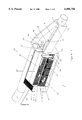
- FIG. 1 depicts a perspective view of a longitudinal partial breakaway of an embodiment of an in-line filter apparatus of the invention in place along a drainage system pipe;
- FIG. 2 depicts a top perspective view of the filter apparatus of FIG. 1;
- FIG. 3 depicts a perspective end view of a partial breakaway of the filter apparatus of FIG. 1;
- FIG. 4 depicts a partial perspective end view of the filter apparatus of FIG. 1.
- the gross pollution filter apparatus 10 of this embodiment is located along a storm water pipework 12 and is arranged to intercept a flow of storm water flowing along the pipework which may be entrained with gross pollutants.
- the filter apparatus will continue to intercept gross pollutants until it becomes totally blocked at which time it is arranged to allow the flow of water and its entrained gross pollutants between its inlet and outlet.
- the inlet 14 of the filter apparatus accommodates a storm water pipe 12 from which water and gross pollutants 16 pass over onto inlet area 18 which has a slight slope toward a water filter means 20.
- Incoming water and gross pollutants are arranged to initially follow a straight path over the inlet area 18 or run adjacent to a side wall 22.
- Flow path 17 also occurs during operation of the filter as depicted in FIG. 2. This flow path is small in comparison to the main flow path 16 but results from the small amount of back pressure at the inlet to the water filter 20 and eventually is drawn back into the main flow path 16 without migrating to the outlet of the filter apparatus.
- the inlet area 18 also extends (not shown in FIG. 1 but illustrated in FIG. 2) over a filtered water path 24 which will be described in greater detail later in the specification.
- Incoming water and gross pollutants 16 are shown as flow path 26 when they enter the water filter 20.
- the water filter 20 is located so as to receive the direct flow of water and gross pollutants from the storm water pipework and comprises an elongate chamber formed with two longitudinal substantially vertical walls of filter elements 28 and 30.
- the filter means also comprises a front lateral substantially vertical wall of filter element 32 as well as a rear lateral substantially vertical wall of impervious material 34 such as concrete.
- the water filter elements 28, 30 and 32 are preferably stainless steel mesh or alternatively may be galvanised mesh having aperture sizes suitable for restricting the passage of a predetermined size of gross pollutant.
- the water filter 20 depicted is a preferable shape and is sized to accommodate a predetermined amount of trapped gross pollutants. The exact quantity deemed sufficient may depend on the desired frequency for emptying the filter as well as the expected amount of gross pollutants which is entrained in the storm water carried by a particular storm water pipe system.
- the water filter 20 becomes a repository for collected gross pollution and should be sized by depth so that it can be emptied with the means available to clean gross pollutants from that depth. For example, vacuum equipment will have an optimum depth at which it will work. Having determined the depth of filter means, the maximum volume of collected gross pollutants will be determined by its length but also by the desired flow capacity of the apertures of the filter elements. Small apertures in the filter elements will require longer or greater areas of filter element to ensure adequate flow of filtered water even though some proportion of the apertures will be blocked by gross pollution.
- the shape of the filter means of this embodiment is rectangular, however, it could be tapered in width from the water filter inlet to the rear wall.
- the water filter could be circular or it could comprise a number of cells one adjacent the other. These cells could be located below the filter elements and could have a variety of shapes.
- sloped walls 34 and 35 are located above the maximum water level of the filter means.
- Wall 34 extends from the top of the filter element 28 across to the top of a channel located adjacent the filter element 28 and a wall (not shown). Sloped walls 34 and 35 keep floating gross pollution out of their respective adjacent channels until the pollution falls into the filter once high flow rates and associated turbulence have subsided.
- the sloped walls also assist in keeping some of the incoming solid pollutants away from the filter elements thus providing a better filter flow condition during high flow rates.
- Filtered water passes through the filter elements 28, 30 and 32 and into the adjacent channels.
- Channels 24 and 64 have been previously described while channel 36 lies adjacent filter element 30.
- Flow arrows 38 and 40 depict the flow of filtered water via channel 36 into channel 24.
- the channels 24, 64 and 36 are all of sufficient volume to accommodate the maximum incoming flow rate.
- Support members 42 are used to space the upright guide channels 44 of the filter element 30 from the wall 46 (not shown in this breakaway depiction of a filter apparatus).
- Outflow from the filter means is depicted by flow arrows 46 and 48 which are merely pictorial representations of the flow path of filtered water once the filter means fills with water and water exits the filter means.
- Water filter outlet 50 is located between the inlet 14 of the filter apparatus and the outlet 52 of the filter apparatus, the outlet 52 being lower than both the water filter outlet 50 and the inlet 14.
- the filtered water exiting the water filter outlet 50 takes a number of paths to the outlet 52.
- the path 54 being the most direct, while path 56 is more circuitous.
- the outlet 50 is shaped so as to encourage a circular flow path such as 56 as is pictorially depicted in FIG. 2.
- barrier wall 58 and the boundary walls 60, 62 and 64 all contribute to the formation of a circular flow pattern of the filtered water exiting the water filter outlet 50. Furthermore, the pressure of the storm water 16 entering the filter apparatus via the inlet 14 acts beyond the end of the barrier wall 56 encouraging the flow path 54 to turn back towards the outlet 52.
- the flow path 54 creates a water barrier to restrain the flow of water and gross pollution between the inlet 14 and the outlet 52.
- the flow capacity of the water filter outlet 52 is equal to or greater than the maximum flow capacity of the inlet 12.
- FIG. 2 more clearly depicts preferable flow paths and also clearly shows the dual purpose of water barrier wall 56.
- Water barrier wall 56 intercepts and directs the majority of initial and continuing flow 16 of incoming water and pollution into the filter means 20 because it protrudes onto outlet side of the line along the pipe system 12. Water barrier wall 56 also prevents filtered water exiting from the water filter outlet 50 mixing immediately with incoming water and pollutants. It is preferable for the distance between the end of the barrier 56 and the nearest wall 60 combined with the height of the channel between the inlet 14 and the outlet 52 to be equal to or greater than the maximum flow volume of the inlet 14 so that in a full by-pass condition the fact that the filter means is full does not create any blockage in the pipework system.
- FIG. 2 also depicts the original storm water pipeline 12-12 as being merely interposed by the filter assembly 10 without requiring realignment of the original pipeline path either in direction or grade. This allows for retrofitting of a filter arrangement into an existing pipe system.
- Flow path 26 is the continuation of incoming flow path 16 within the filter means.
- Flow within the filter means can be vigorous and turbulent during high flow rates and most all the gross pollution will be entrained within the filter means 20. However, smaller particles, suspended particles and of course dissolved pollutants move through the filter members 28, 30 and 32 as depicted in FIG. 2.
- the flow paths associated with filter member 30 are shown as arrows 40 and 42 into channel 36 and those associated with filter member 30 are shown as flow arrows 60 and 62 into channel 64.
- Both channels 36 and 64 are quieter regions of the filter means and some of the smaller and suspended particles are able to settle to the bottom of the channel ready for extraction when the filter apparatus is cleaned out.
- Channels 36, 64 and 24 are the last water communication paths of the filter means before reaching the filter outlet 50. Although, not preferable, a further channel could be created to the rear of the filter means this additional channel is not necessary for adequate operation of the filter arrangement.
- each channel in combination with its depth is preferably capable of sustaining a flow volume equal to the maximum flow volume of the input 14 so as to ensure that filtered water has minimum resistance to flow towards the filter outlet 50.
- channels 36, 64 and 24 are arranged to have one or more baffles 66 and 68 (as depicted in FIGS. 2, 3 and 4) so as to restrict the flow of floating pollutants such as oil, grease etc, across the top of the filtered water and thereby prevent it from entering the filter output 50 and then into the apparatus outlet 52.
- baffles 66 and 68 as depicted in FIGS. 2, 3 and 4
- baffles 66 and 68 are located in the front top regions of the channels 36 and 64 respectively and will work if the water level in the filter means is kept up to the outlet level of the filter means.
- the volume below the baffles should also preferably be sufficient to allow the maximum flow rate of the inlet 14 to pass therethrough thereby continuing the ability for the filter means to work at maximum flow rates.
- baffles are only preferable since sometimes the filter arrangement will suffice to filter solid and some suspended pollutants with little concern for oil and grease since that may be a small constituent of the incoming gross pollution.
- a siphon tube 70 as depicted in FIGS. 1, 2 and 3 is an optional element of the filter arrangement of the invention. Siphoning is sometimes required to remove still water from the filter means which could otherwise become a breeding area for mosquitos and other insects, as well as decaying matter which could become a health hazard.
- the hydraulic loss of the filter arrangement at both high and low flow rates is very similar but account is required of the small head loss created by the additional turbulence created by the water barrier arrangement.
- the filter arrangement of the invention avoids this and ensures that during by-pass conditions the flow properties of the pipework system are not degraded in any substantial way.
- the embodiment of the filter arrangement of the invention disclosed in this specification is also arranged to minimise areas of dead water, but other variations of the embodiment may also exist to achieve the aims of the invention while also being able to minimise dead water regions.
- the materials used to construct the embodiment of the filter arrangement of this invention are primarily concrete and perforated stainless steel sheeting. However, different applications such as in chemical factories may require use of lighter materials such as plastics and aluminium or which may have special characteristics for use with certain chemicals.
- Perforated stainless steel sheets are the preferred filter element material since they may be easily cut to size and are readily replaceable. Furthermore, a variety of standard perforated stainless steel sheets having not only a variety of sizes but a variety of aperture sizes are readily available thus making the choice of aperture size a matter of what minimum size of pollutants is designed to be filtered, while ensuring that total aperture volume provided in each of the sheets is great enough to accommodate the anticipated flow rates.
- the overflow condition provides a flow path which is self cleaning and is the same grade as the existing pipework, therefore ensuring no buildup at either the entrance or the exit of the filter apparatus of gross pollutants and a maintenance of hydraulic flow characteristics of the existing water pipe system.
Abstract
A water filter arrangement (10) for trapping gross pollutants flowing in a storm water system is provided in-line or at end-of-line of a storm water pipe. The arrangement comprises an inlet (14) and an inlet area (18) which directs incoming water (16) into a filter (20). The filter traps entrained gross pollutants and filtered water exits the filter via filter outlet (50). The outlet (50) and surrounding walls (58 and 57) are shaped to create a flow of filtered water which forms a water barrier which restrains the flow of water and gross pollutants from the inlet (14) to the outlet (52). The water barrier is located between the inlet (14) and the outlet (52) preferably closer to the outlet than the inlet. As the filter (20) becomes full and the flow of filtered water exiting the filter decreases the water barrier subsides. When the filter is completely blocked, the water barrier completely subsides and the incoming water and gross pollutants by-pass the filter (20) and flow unrestrained without head loss from the inlet (14) to the outlet (52).
Description
This invention relates to a gross pollution filter apparatus for use in a water drainage system and in particular to a filter for capturing gross pollution along or at a termination point of a storm water drainage system.
Water quality degradation is a problem of growing proportions. One measure of water quality is the amount of gross pollution that is carried from our roads and streets into our storm water system and eventually into the reservoirs that we rely on for potable water. Our rivers, lakes, dams and ultimately the ocean are becoming the repository for gross pollution which is lowering the quality of those very important water sources.
Gross pollution in the main (90%) comprises organic matter like branches, twigs, leaves, and soil, the remainder being non-organic matter like plastic containers, bags, wrappers; paper; cans; and cigarette butts.
In one example of a storm water drainage system, storm water collected from metropolitan and township road surfaces and household roofs ends up in the underground storm water drainage system. Ground level storm water entry points called gully traps let a variety of various sizes of gross pollution into the storm water drainage system. Typical drainage systems comprise underground pipes and sometimes exposed water conduits, which carry storm water to holding reservoirs, rivers and ocean outflows.
Gross pollution is likely to accumulate in large quantities at the outflows of drainage systems and concern about the environmental impact of high concentrations of this gross pollution is justified.
Filtering of storm water using current techniques is a costly and time consuming undertaking and it is not unusual for water authorities to prefer to address the problem by cleaning up the very visible consequences of gross pollution which emits from the drainage system rather than actually reducing the contamination of the storm water system at its source. Sometimes gross pollution or filtering is undertaken at intermediate points along the drainage system but the typical approach is to install end of line grates which tend to quickly foul up and require constant maintenance and which do not deal with oil and oil like contaminates.
Similar considerations also apply to the treatment of polluted industrial water.
Some of the less than desirable features of prior and current storm water and gross pollution filters include:
use of many metal parts which require anti-rusting treatment or use of expensive stainless steel elements
moving parts which require maintenance and periodic replacement, and which are liable to jam, corrode and require frequent cleaning to maintain their efficiency
use of large areas adjacent the existing drainage system for providing settling reservoirs which are sometimes many times wider than the drains and conduits with which they are associated
high hydraulic head loss between the inlet and outlet resulting in low filter efficiency at low and high flow rates and great disruption to the drainage layout providing unwanted restrictions and prohibitions to the retrofitting of such filters to existing drainage systems
small time intervals between pollution collection are required when many small gross pollution filters are incorporated into the drainage system and further, existing shapes of pollutant collection volumes are often difficult to empty and clean
in-line grate type filters for different types of pollutants require large areas to handle the some time large volumes of gross pollutants and which have a large potential for blockage as well as often requiring the manufacture of unique elements at greater cost than desirable
different efficiency at different flow rates, and often the poorest efficiency occurs at both low and high flow rates
blockages caused particularly by sediment build up at the inlet and outlet of the filter apparatus and the accumulation of certain types of pollutants can be a health hazard and cause unnecessary use of overflow routes which bypass the filter apparatus
prior arrangements also include apertured and solid weirs which induce a back pressure along the incoming storm water pipe during and certainly after the filter arrangement becomes inefficient and unable to adequately filter the flow of incoming storm water carrying gross pollutants.
These and other problems are reduced or eliminated by the invention disclosed herein.
In its broadest form a gross pollution filter apparatus for use in water drainage systems carrying water and gross pollution, the apparatus comprising an inlet, an outlet lower than said inlet, a water filter means forming a holding chamber means for retaining a portion of the gross pollution, the filter means being located below the level of the inlet, and, having a water filter means outlet located at a level between said inlet and said outlet arranged so that filtered water flowing out the water filter outlet creates a water barrier to the flow of water and gross pollution between the inlet and the outlet.
In a further aspect of the invention the water barrier subsides when the flow of water through the filter means decreases such that water and gross pollution passes more easily from the inlet to the outlet than from the inlet into the filter means.
In a further aspect of the invention the water barrier is located adjacent the outlet.
Embodiments of the invention will now be described in some further detail with reference to and as illustrated in the accompanying figures. These embodiments are illustrative and not meant to be restrictive of the scope of the invention.
FIG. 1 depicts a perspective view of a longitudinal partial breakaway of an embodiment of an in-line filter apparatus of the invention in place along a drainage system pipe;
FIG. 2 depicts a top perspective view of the filter apparatus of FIG. 1;
FIG. 3 depicts a perspective end view of a partial breakaway of the filter apparatus of FIG. 1; and
FIG. 4 depicts a partial perspective end view of the filter apparatus of FIG. 1.
The gross pollution filter apparatus 10 of this embodiment is located along a storm water pipework 12 and is arranged to intercept a flow of storm water flowing along the pipework which may be entrained with gross pollutants.
The filter apparatus will continue to intercept gross pollutants until it becomes totally blocked at which time it is arranged to allow the flow of water and its entrained gross pollutants between its inlet and outlet.
The inlet 14 of the filter apparatus accommodates a storm water pipe 12 from which water and gross pollutants 16 pass over onto inlet area 18 which has a slight slope toward a water filter means 20.
Incoming water and gross pollutants are arranged to initially follow a straight path over the inlet area 18 or run adjacent to a side wall 22. Flow path 17 also occurs during operation of the filter as depicted in FIG. 2. This flow path is small in comparison to the main flow path 16 but results from the small amount of back pressure at the inlet to the water filter 20 and eventually is drawn back into the main flow path 16 without migrating to the outlet of the filter apparatus.
The inlet area 18 also extends (not shown in FIG. 1 but illustrated in FIG. 2) over a filtered water path 24 which will be described in greater detail later in the specification. Incoming water and gross pollutants 16 are shown as flow path 26 when they enter the water filter 20. The water filter 20 is located so as to receive the direct flow of water and gross pollutants from the storm water pipework and comprises an elongate chamber formed with two longitudinal substantially vertical walls of filter elements 28 and 30. The filter means also comprises a front lateral substantially vertical wall of filter element 32 as well as a rear lateral substantially vertical wall of impervious material 34 such as concrete.
The water filter elements 28, 30 and 32 are preferably stainless steel mesh or alternatively may be galvanised mesh having aperture sizes suitable for restricting the passage of a predetermined size of gross pollutant.
The water filter 20 depicted is a preferable shape and is sized to accommodate a predetermined amount of trapped gross pollutants. The exact quantity deemed sufficient may depend on the desired frequency for emptying the filter as well as the expected amount of gross pollutants which is entrained in the storm water carried by a particular storm water pipe system.
The water filter 20 becomes a repository for collected gross pollution and should be sized by depth so that it can be emptied with the means available to clean gross pollutants from that depth. For example, vacuum equipment will have an optimum depth at which it will work. Having determined the depth of filter means, the maximum volume of collected gross pollutants will be determined by its length but also by the desired flow capacity of the apertures of the filter elements. Small apertures in the filter elements will require longer or greater areas of filter element to ensure adequate flow of filtered water even though some proportion of the apertures will be blocked by gross pollution.
The shape of the filter means of this embodiment is rectangular, however, it could be tapered in width from the water filter inlet to the rear wall. Alternatively the water filter could be circular or it could comprise a number of cells one adjacent the other. These cells could be located below the filter elements and could have a variety of shapes.
It has been found that the majority of the contained gross pollution collects near the entry point to the filter means. Floating or buoyant gross pollution will eventually become rotted or water logged and sink to the bottom of the filter means. The sloped walls 34 and 35 (wall 34 is depicted in FIG. 1 and wall 35 is depicted in FIG. 3) are located above the maximum water level of the filter means. Wall 34 extends from the top of the filter element 28 across to the top of a channel located adjacent the filter element 28 and a wall (not shown). Sloped walls 34 and 35 keep floating gross pollution out of their respective adjacent channels until the pollution falls into the filter once high flow rates and associated turbulence have subsided.
The sloped walls also assist in keeping some of the incoming solid pollutants away from the filter elements thus providing a better filter flow condition during high flow rates.
It is a disadvantage to have the filter elements (as depicted in FIGS. 1 and 2) extend above the maximum water height in the filter means, since that portion above the maximum water height would soon become slicked up with pollutants and thereafter fail to act as a filter in any event.
Filtered water passes through the filter elements 28, 30 and 32 and into the adjacent channels. Channels 24 and 64 have been previously described while channel 36 lies adjacent filter element 30. Flow arrows 38 and 40 depict the flow of filtered water via channel 36 into channel 24.
The channels 24, 64 and 36 are all of sufficient volume to accommodate the maximum incoming flow rate.
Support members 42 (as shown in FIG. 1) are used to space the upright guide channels 44 of the filter element 30 from the wall 46 (not shown in this breakaway depiction of a filter apparatus).
Outflow from the filter means is depicted by flow arrows 46 and 48 which are merely pictorial representations of the flow path of filtered water once the filter means fills with water and water exits the filter means.
As is more clearly depicted in FIG. 2, the filtered water exiting the water filter outlet 50 takes a number of paths to the outlet 52. The path 54 being the most direct, while path 56 is more circuitous. The outlet 50 is shaped so as to encourage a circular flow path such as 56 as is pictorially depicted in FIG. 2.
Furthermore, barrier wall 58 and the boundary walls 60, 62 and 64 all contribute to the formation of a circular flow pattern of the filtered water exiting the water filter outlet 50. Furthermore, the pressure of the storm water 16 entering the filter apparatus via the inlet 14 acts beyond the end of the barrier wall 56 encouraging the flow path 54 to turn back towards the outlet 52.
The flow path 54 creates a water barrier to restrain the flow of water and gross pollution between the inlet 14 and the outlet 52.
It is preferable for the flow capacity of the water filter outlet 52 to be equal to or greater than the maximum flow capacity of the inlet 12.
FIG. 2 more clearly depicts preferable flow paths and also clearly shows the dual purpose of water barrier wall 56.
FIG. 2 also depicts the original storm water pipeline 12-12 as being merely interposed by the filter assembly 10 without requiring realignment of the original pipeline path either in direction or grade. This allows for retrofitting of a filter arrangement into an existing pipe system.
Flow path 26 is the continuation of incoming flow path 16 within the filter means. Flow within the filter means can be vigorous and turbulent during high flow rates and most all the gross pollution will be entrained within the filter means 20. However, smaller particles, suspended particles and of course dissolved pollutants move through the filter members 28, 30 and 32 as depicted in FIG. 2. The flow paths associated with filter member 30 are shown as arrows 40 and 42 into channel 36 and those associated with filter member 30 are shown as flow arrows 60 and 62 into channel 64.
Both channels 36 and 64 are quieter regions of the filter means and some of the smaller and suspended particles are able to settle to the bottom of the channel ready for extraction when the filter apparatus is cleaned out.
The width of each channel in combination with its depth is preferably capable of sustaining a flow volume equal to the maximum flow volume of the input 14 so as to ensure that filtered water has minimum resistance to flow towards the filter outlet 50.
Preferably, channels 36, 64 and 24 are arranged to have one or more baffles 66 and 68 (as depicted in FIGS. 2, 3 and 4) so as to restrict the flow of floating pollutants such as oil, grease etc, across the top of the filtered water and thereby prevent it from entering the filter output 50 and then into the apparatus outlet 52.
These baffles 66 and 68 are located in the front top regions of the channels 36 and 64 respectively and will work if the water level in the filter means is kept up to the outlet level of the filter means. The volume below the baffles should also preferably be sufficient to allow the maximum flow rate of the inlet 14 to pass therethrough thereby continuing the ability for the filter means to work at maximum flow rates.
The use of baffles is only preferable since sometimes the filter arrangement will suffice to filter solid and some suspended pollutants with little concern for oil and grease since that may be a small constituent of the incoming gross pollution.
A siphon tube 70 as depicted in FIGS. 1, 2 and 3 is an optional element of the filter arrangement of the invention. Siphoning is sometimes required to remove still water from the filter means which could otherwise become a breeding area for mosquitos and other insects, as well as decaying matter which could become a health hazard.
In high flow rate circumstances the majority of incoming water and pollutants are restrained by the filter means 20 and the flow of filtered water exits the filter outlet 50 and then leaves the filter apparatus through its outlet 52. The water barrier created during this high flow circumstance keeps the incoming water and pollution separate from the filtered outgoing water.
However, it has been found that this is also the case for low flow rate situations and the water barrier is equally effective.
The hydraulic loss of the filter arrangement at both high and low flow rates is very similar but account is required of the small head loss created by the additional turbulence created by the water barrier arrangement.
There is however a very great advantage of the filter arrangement of the invention when the filter means becomes clogged with gross pollutants. As the resistance of water flowing through the filter member becomes greater its consequence is to reduce the effectiveness of the water barrier and thus make it easier for incoming water and pollutants to flow directly to the outlet from the inlet, and when this flow path is used there is little or no head loss during this filter by-pass operation.
This characteristic is in stark contrast to other filter arrangements for example weirs, which when they become blocked require the incoming water to overflow the blocked weir causing maximum head loss during the overflow condition and which also encourages gross pollution to back up into the feeding pipework system. This situation remains until the weir is cleared of gross pollution.
Clearly, the filter arrangement of the invention avoids this and ensures that during by-pass conditions the flow properties of the pipework system are not degraded in any substantial way.
The embodiment of the filter arrangement of the invention disclosed in this specification is also arranged to minimise areas of dead water, but other variations of the embodiment may also exist to achieve the aims of the invention while also being able to minimise dead water regions.
In this embodiment of the filter arrangement there is only one filter means exit located so as to maximise the amount and location of filtered water to create a water barrier. There are however other possible arrangements which could provide for more than one filter means exit and more than one water barrier while still achieving the aims of the invention.
The materials used to construct the embodiment of the filter arrangement of this invention are primarily concrete and perforated stainless steel sheeting. However, different applications such as in chemical factories may require use of lighter materials such as plastics and aluminium or which may have special characteristics for use with certain chemicals.
Perforated stainless steel sheets are the preferred filter element material since they may be easily cut to size and are readily replaceable. Furthermore, a variety of standard perforated stainless steel sheets having not only a variety of sizes but a variety of aperture sizes are readily available thus making the choice of aperture size a matter of what minimum size of pollutants is designed to be filtered, while ensuring that total aperture volume provided in each of the sheets is great enough to accommodate the anticipated flow rates.
It is preferable that there be a smooth transition between the pipe 12 into the filter apparatus at its inlet 14 and also at the outlet 52 of the filter apparatus. Likewise it is preferable for there to be a clean transition from the filter means outlet 50 to the path between the inlet 14 and the outlet 52 of the filter apparatus.
It is also preferable for all of the upper surfaces of the filter apparatus to be capped with removable covers. This provides for safety and an allowance for access for cleaning and maintenance.
It will be noted that the overflow condition provides a flow path which is self cleaning and is the same grade as the existing pipework, therefore ensuring no buildup at either the entrance or the exit of the filter apparatus of gross pollutants and a maintenance of hydraulic flow characteristics of the existing water pipe system.
It will be appreciated by those skilled in the art, that the invention is not restricted in its use to the particular application described, nor is it restricted to the feature of the preferred embodiment described herein. It will be appreciated that various modifications can be made without departing from the principles of the invention, therefore, the invention should be understood to include all such modifications within its scope.
Claims (16)
1. A gross pollution filter apparatus for use in water drainage systems carrying water and gross pollution said apparatus comprising
an inlet,
an outlet lower than said inlet,
a water filter means forming a holding chamber means for retaining a portion of said gross pollution, said filter means located below the level of said inlet, and, a water filter means outlet located at a level between said inlet and said outlet arranged so that filtered water flowing out said water filter outlet creates a water barrier to the flow of water and gross pollution between said inlet and said outlet.
2. A gross pollution filter apparatus according to claim 1 wherein said water barrier subsides when the flow of water through said filter means decreases such that water and gross pollution passes more easily from said inlet to said outlet than from said inlet into said filter means.
3. A gross pollution filter apparatus according to claim 1 wherein said water barrier is located adjacent said outlet.
4. A gross pollution filter apparatus according to claim 1 wherein said filter means is located in the existing line and flow grade of said drainage system.
5. A gross pollution filter apparatus according to claim 1 wherein said filter means comprises vertical filter elements reaching from the bottom of said filter means volume to the level of said water filter output providing water communication between said inlet and said water filter outlet.
6. A gross pollution filter apparatus according to claim 5 wherein one or more of said filter elements are removable for replacement or cleaning.
7. A gross pollution filter apparatus according to claim 1 further comprising a stilling volume located in the fluid communication path between said filter means and said filter means outlet.
8. A gross pollution filter apparatus according to claim 7 wherein said stilling volume adjacent said filter means has at least one baffle located therein so as to restrict the flow of floating pollutants to said filter means outlet being those pollutants which have not been retained within said filter.
9. A gross pollution filter apparatus according to claim 1 wherein the flow capacity of said filter means outlet is at least equal to the flow capacity of said inlet flow capacity.
10. A gross pollution filter apparatus according to claim 1 wherein the volume of storm water entering said filter means from said inlet is restricted by a restriction means.
11. A gross pollution filter apparatus according to claim 10 wherein said restriction means comprises a tapered cavity formed partially by an inlet area and side wall members and a lid member resting upon said side wall members.
12. A gross pollution filter apparatus according to claim 1 further comprising a siphon means located between said filter means and the exterior of said apparatus for siphoning water from said filter means.
13. A gross pollution filter apparatus according to claim 1 wherein said filter means has a removable top member to allow for access to said filter means for cleaning and maintenance.
14. A gross pollution filter apparatus according to claim 1 wherein said inlet is located so as to provide a water and gross pollutant path adjacent a director means into said filter means.
15. A gross pollution filter apparatus according to claim 14 wherein said inlet water and gross pollutant path are located adjacent a wall.
16. A gross pollution filter apparatus according to claim 14 wherein each said water path has a flow volume of at least the flow volume of said inlet.
Applications Claiming Priority (17)
| Application Number | Priority Date | Filing Date | Title |
|---|---|---|---|
| AUPO3127A AUPO312796A0 (en) | 1996-10-23 | 1996-10-23 | Rapid filtration system |
| AUPO3127 | 1996-10-23 | ||
| AUPO3941 | 1996-12-02 | ||
| AUPO3941A AUPO394196A0 (en) | 1996-12-02 | 1996-12-02 | Rapid stormwater filtration |
| AUPO4080 | 1996-12-10 | ||
| AUPO4080A AUPO408096A0 (en) | 1996-12-10 | 1996-12-10 | Rapid stormwater filtration |
| AUPO4821 | 1997-01-29 | ||
| AUPO4821A AUPO482197A0 (en) | 1997-01-29 | 1997-01-29 | Rapid stormwater filtration |
| AUPO5086A AUPO508697A0 (en) | 1997-02-13 | 1997-02-13 | In-line storm water filter |
| AUPO5086 | 1997-02-13 | ||
| AUPO5615A AUPO561597A0 (en) | 1997-03-13 | 1997-03-13 | Rapid stormwater filtration |
| AUPO5615 | 1997-03-13 | ||
| AUPO8607 | 1997-08-15 | ||
| AUPO8607A AUPO860797A0 (en) | 1997-08-15 | 1997-08-15 | Rapid stormwater filtration |
| AUPO9381 | 1997-09-24 | ||
| AUPO9381A AUPO938197A0 (en) | 1997-09-24 | 1997-09-24 | Rapid stormwater filtration |
| PCT/AU1997/000710 WO1998017875A1 (en) | 1996-10-23 | 1997-10-23 | Gross pollution filter |
Publications (1)
| Publication Number | Publication Date |
|---|---|
| US6086756A true US6086756A (en) | 2000-07-11 |
Family
ID=27570134
Family Applications (1)
| Application Number | Title | Priority Date | Filing Date |
|---|---|---|---|
| US09/284,938 Expired - Fee Related US6086756A (en) | 1996-10-23 | 1997-10-23 | Gross pollution filter |
Country Status (8)
| Country | Link |
|---|---|
| US (1) | US6086756A (en) |
| EP (1) | EP0935699B1 (en) |
| JP (1) | JP3935216B2 (en) |
| AT (1) | ATE316173T1 (en) |
| CA (1) | CA2269615C (en) |
| DE (1) | DE69735140D1 (en) |
| NZ (1) | NZ335378A (en) |
| WO (1) | WO1998017875A1 (en) |
Cited By (34)
| Publication number | Priority date | Publication date | Assignee | Title |
|---|---|---|---|---|
| US6241881B1 (en) * | 1997-11-21 | 2001-06-05 | University Of South Australia | Pollution separator and filtration apparatus |
| US6358405B1 (en) * | 1997-09-03 | 2002-03-19 | Brian Warren Leahy | Pollutant interceptor |
| US6428692B2 (en) * | 2000-05-30 | 2002-08-06 | Henry Happel | In-line storm water drain filter system |
| US6464862B2 (en) * | 2000-03-13 | 2002-10-15 | Baramy Engineering Pty Ltd. | Gross pollutant trap |
| US20030116485A1 (en) * | 2000-05-12 | 2003-06-26 | Phillips Donald Ian | Solids/liquids separator |
| US20030127377A1 (en) * | 2001-02-26 | 2003-07-10 | Pank Thomas E. | Stormwater treatment train |
| US20040040598A1 (en) * | 2002-08-30 | 2004-03-04 | Zimmerman Robert L. | Rainwater recovery system |
| US20040134843A1 (en) * | 2001-03-07 | 2004-07-15 | Kolb Frank Rainer | Waste water installation with purification device |
| US20040251185A1 (en) * | 2003-06-10 | 2004-12-16 | Pitt Robert E. | Upflow surface water runoff filtration system |
| US20050056587A1 (en) * | 2003-09-17 | 2005-03-17 | Vortechnics, Inc. | Apparatus for separating floating and non-floating particulate from a fluid stream |
| US6869528B2 (en) | 2001-02-26 | 2005-03-22 | Thomas E. Pank | Filtering system for runoff water |
| US20050103698A1 (en) * | 2003-11-14 | 2005-05-19 | Eberly Christopher N. | System for stormwater environmental control |
| US20070056889A1 (en) * | 2005-09-09 | 2007-03-15 | Cds Technologies, Inc. | Apparatus for separating solids from flowing liquids |
| US20080149188A1 (en) * | 2002-08-30 | 2008-06-26 | Charles River Watershed Association | Modular blocks for rainwater recovery system |
| US20080164190A1 (en) * | 2006-11-15 | 2008-07-10 | David Pezzaniti | Curbside gross pollution trap |
| US20080277327A1 (en) * | 2007-05-09 | 2008-11-13 | Contech Stormwater Solutions, Inc. | Stormwater Filter Assembly |
| US7459090B1 (en) * | 2007-04-27 | 2008-12-02 | Lane Enterprises, Inc. | Stormwater treatment system and method |
| US20090045128A1 (en) * | 2007-08-15 | 2009-02-19 | Christopher Adam Murray | Filter For Removing Sediment From Water |
| US7799235B2 (en) | 2004-07-23 | 2010-09-21 | Contech Stormwater Solutions, Inc. | Fluid filter system and related method |
| US20110000862A1 (en) * | 2008-02-19 | 2011-01-06 | Hanex Co., Ltd. | Separator and separation method |
| US8221618B2 (en) * | 2007-08-15 | 2012-07-17 | Monteco Ltd. | Filter for removing sediment from water |
| US8287726B2 (en) | 2007-08-15 | 2012-10-16 | Monteco Ltd | Filter for removing sediment from water |
| CN101705719B (en) * | 2008-08-08 | 2013-01-02 | 梁敬喜 | Automatic processor of domestic sewage |
| US8366923B1 (en) * | 2007-11-19 | 2013-02-05 | Tom Happel | Telescoping post supports and sliding lid systems for filter baskets |
| US20140138298A1 (en) * | 2012-10-10 | 2014-05-22 | Jared Joseph Schoepf | Grate filtration system |
| US10238993B1 (en) | 2013-05-30 | 2019-03-26 | Suntree Technologies Holdings, Llc | Dual screen treatment systems with debris ramps and screened deflectors |
| US10294653B2 (en) * | 2016-10-13 | 2019-05-21 | Amiantit Germany Gmbh | Rain overflow basin for collecting and storing water |
| US10472815B1 (en) | 2013-05-30 | 2019-11-12 | Oldcastle Infrastructure, Inc. | Hydro-variant baffle cartridge system |
| CN111346414A (en) * | 2020-03-13 | 2020-06-30 | 陈爱华 | Automatic environmental protection processing system of waste water |
| US10907338B1 (en) | 2013-05-30 | 2021-02-02 | Oldcastle Infrastructure, Inc. | Hinged variable flow skimmer and shelf system |
| US10926199B1 (en) | 2013-05-30 | 2021-02-23 | Oldcastle Infrastructure, Inc. | Round baffle box water treatment system with at least one sidewall baffle |
| US20220023778A1 (en) * | 2020-07-27 | 2022-01-27 | Pre-Con Products | Double-Filter Basket for StormWater Retention System Drain |
| US11253798B2 (en) | 2013-05-30 | 2022-02-22 | Oldcastle Infrastructure, Inc. | Nutrient removal filtration system and method |
| US20220213677A1 (en) * | 2021-01-04 | 2022-07-07 | United States Government As Represented By The Secretary Of The Navy | In-Pipe Storm Water Filter |
Families Citing this family (5)
| Publication number | Priority date | Publication date | Assignee | Title |
|---|---|---|---|---|
| AUPP418198A0 (en) * | 1998-06-17 | 1998-07-09 | Turco, Eugene | A screening apparatus |
| AUPQ867600A0 (en) * | 2000-07-10 | 2000-08-03 | Central Moreton Industries Pty Ltd | A filter assembly |
| FR2832646B1 (en) * | 2001-11-23 | 2004-02-20 | Ams Brinex | SEPARATOR FOR THE TREATMENT OF LOADED WATER, ESPECIALLY HYDROCARBONS OR SLUDGE |
| AU2013286804A1 (en) * | 2012-07-02 | 2015-01-22 | Water Decontamination Technologies Pty Ltd | Improved filter for polluted water |
| CN104099996A (en) * | 2014-06-30 | 2014-10-15 | 武汉圣禹排水系统有限公司 | Rainwater inlet with water filtering barrel |
Citations (8)
| Publication number | Priority date | Publication date | Assignee | Title |
|---|---|---|---|---|
| US1903774A (en) * | 1931-06-17 | 1933-04-18 | Benjamin S Burrell | Screener equipped pipe line |
| US5498331A (en) * | 1994-11-08 | 1996-03-12 | 1137361 Ontario Limited | Tank interceptor |
| US5531888A (en) * | 1993-07-28 | 1996-07-02 | Vsb Vogelsberger Umwelttechnischer Anlagenbau Gmbh | Arrangement for separation of coarse matter and/or bulky solids in rainwater relief structures |
| AU7178696A (en) * | 1995-11-15 | 1997-05-22 | Csr Humes Pty. Limited | Gross pollutant trap |
| US5746911A (en) * | 1997-01-13 | 1998-05-05 | Pank; Thomas E. | Apparatus for separating a light from a heavy fluid |
| US5779888A (en) * | 1995-09-04 | 1998-07-14 | Baramy Engineering Pty. Ltd. | Filtering apparatus |
| US5788848A (en) * | 1994-06-17 | 1998-08-04 | Cds Tech Ltd | Apparatus and methods for separating solids from flowing liquids or gases |
| US5904842A (en) * | 1995-08-28 | 1999-05-18 | Billias; Charles | Removable storm water devices |
Family Cites Families (3)
| Publication number | Priority date | Publication date | Assignee | Title |
|---|---|---|---|---|
| JP3725897B2 (en) * | 1993-02-11 | 2005-12-14 | クロンプトン,ステファン | Apparatus for separating solids from a flowing liquid |
| SE501160C2 (en) * | 1994-01-13 | 1994-11-28 | Va Teknik I Boraas Ab | Process for purifying wastewater by means of compulsory swirling of incoming water and apparatus for carrying out the process |
| AU677767B3 (en) * | 1996-02-26 | 1997-05-01 | Diston Sewage Purification Pty Ltd | Storm water litter separation |
-
1997
- 1997-10-23 DE DE69735140T patent/DE69735140D1/en not_active Expired - Lifetime
- 1997-10-23 NZ NZ335378A patent/NZ335378A/en not_active IP Right Cessation
- 1997-10-23 EP EP97944642A patent/EP0935699B1/en not_active Expired - Lifetime
- 1997-10-23 US US09/284,938 patent/US6086756A/en not_active Expired - Fee Related
- 1997-10-23 JP JP51873398A patent/JP3935216B2/en not_active Expired - Fee Related
- 1997-10-23 CA CA002269615A patent/CA2269615C/en not_active Expired - Fee Related
- 1997-10-23 WO PCT/AU1997/000710 patent/WO1998017875A1/en active IP Right Grant
- 1997-10-23 AT AT97944642T patent/ATE316173T1/en not_active IP Right Cessation
Patent Citations (8)
| Publication number | Priority date | Publication date | Assignee | Title |
|---|---|---|---|---|
| US1903774A (en) * | 1931-06-17 | 1933-04-18 | Benjamin S Burrell | Screener equipped pipe line |
| US5531888A (en) * | 1993-07-28 | 1996-07-02 | Vsb Vogelsberger Umwelttechnischer Anlagenbau Gmbh | Arrangement for separation of coarse matter and/or bulky solids in rainwater relief structures |
| US5788848A (en) * | 1994-06-17 | 1998-08-04 | Cds Tech Ltd | Apparatus and methods for separating solids from flowing liquids or gases |
| US5498331A (en) * | 1994-11-08 | 1996-03-12 | 1137361 Ontario Limited | Tank interceptor |
| US5904842A (en) * | 1995-08-28 | 1999-05-18 | Billias; Charles | Removable storm water devices |
| US5779888A (en) * | 1995-09-04 | 1998-07-14 | Baramy Engineering Pty. Ltd. | Filtering apparatus |
| AU7178696A (en) * | 1995-11-15 | 1997-05-22 | Csr Humes Pty. Limited | Gross pollutant trap |
| US5746911A (en) * | 1997-01-13 | 1998-05-05 | Pank; Thomas E. | Apparatus for separating a light from a heavy fluid |
Cited By (53)
| Publication number | Priority date | Publication date | Assignee | Title |
|---|---|---|---|---|
| US6358405B1 (en) * | 1997-09-03 | 2002-03-19 | Brian Warren Leahy | Pollutant interceptor |
| US6241881B1 (en) * | 1997-11-21 | 2001-06-05 | University Of South Australia | Pollution separator and filtration apparatus |
| US6464862B2 (en) * | 2000-03-13 | 2002-10-15 | Baramy Engineering Pty Ltd. | Gross pollutant trap |
| US7441661B2 (en) | 2000-05-12 | 2008-10-28 | Water Solutions (Aust) Pty Ltd. | Solids/liquids separator |
| US20030116485A1 (en) * | 2000-05-12 | 2003-06-26 | Phillips Donald Ian | Solids/liquids separator |
| US20050167344A1 (en) * | 2000-05-12 | 2005-08-04 | Joseph Rodriguez | Solids/liquids separator |
| US6868971B2 (en) * | 2000-05-12 | 2005-03-22 | Water Solutions (Aust) Pty Ltd. | Solids/liquids separator |
| US6428692B2 (en) * | 2000-05-30 | 2002-08-06 | Henry Happel | In-line storm water drain filter system |
| US6869528B2 (en) | 2001-02-26 | 2005-03-22 | Thomas E. Pank | Filtering system for runoff water |
| US20030127377A1 (en) * | 2001-02-26 | 2003-07-10 | Pank Thomas E. | Stormwater treatment train |
| US7182856B2 (en) | 2001-02-26 | 2007-02-27 | Pank Thomas E | Stormwater treatment train |
| US7674371B2 (en) * | 2001-03-07 | 2010-03-09 | Frank Rainer Kolb | Waste water installation with purification device |
| US20040134843A1 (en) * | 2001-03-07 | 2004-07-15 | Kolb Frank Rainer | Waste water installation with purification device |
| US20040040598A1 (en) * | 2002-08-30 | 2004-03-04 | Zimmerman Robert L. | Rainwater recovery system |
| US7025076B2 (en) | 2002-08-30 | 2006-04-11 | Charles River Watershed Association | Rainwater recovery system |
| US20080149188A1 (en) * | 2002-08-30 | 2008-06-26 | Charles River Watershed Association | Modular blocks for rainwater recovery system |
| US7005060B2 (en) | 2003-06-10 | 2006-02-28 | Stormtrain Llc | Upflow surface water runoff filtration system |
| US20040251185A1 (en) * | 2003-06-10 | 2004-12-16 | Pitt Robert E. | Upflow surface water runoff filtration system |
| US6991114B2 (en) | 2003-09-17 | 2006-01-31 | Vortechnics, Inc. | Apparatus for separating floating and non-floating particulate from a fluid stream |
| US20050056587A1 (en) * | 2003-09-17 | 2005-03-17 | Vortechnics, Inc. | Apparatus for separating floating and non-floating particulate from a fluid stream |
| US7296692B2 (en) | 2003-09-17 | 2007-11-20 | Contech Stormwater Solutions Inc. | Apparatus for separating floating and non-floating particulate from a fluid stream |
| US7297266B2 (en) | 2003-09-17 | 2007-11-20 | Contech Stormwater Solutions Inc. | Apparatus for separating particulates from a fluid stream |
| US20050103698A1 (en) * | 2003-11-14 | 2005-05-19 | Eberly Christopher N. | System for stormwater environmental control |
| US7780855B2 (en) | 2003-11-14 | 2010-08-24 | Eberly Christopher N | Method for pre-engineering a system for environmental control of storm water |
| US7470361B2 (en) | 2003-11-14 | 2008-12-30 | Eberly Christopher N | System for stormwater environmental control |
| US7799235B2 (en) | 2004-07-23 | 2010-09-21 | Contech Stormwater Solutions, Inc. | Fluid filter system and related method |
| US7465391B2 (en) * | 2005-09-09 | 2008-12-16 | Cds Technologies, Inc. | Apparatus for separating solids from flowing liquids |
| US20070056889A1 (en) * | 2005-09-09 | 2007-03-15 | Cds Technologies, Inc. | Apparatus for separating solids from flowing liquids |
| US20080164190A1 (en) * | 2006-11-15 | 2008-07-10 | David Pezzaniti | Curbside gross pollution trap |
| US7459090B1 (en) * | 2007-04-27 | 2008-12-02 | Lane Enterprises, Inc. | Stormwater treatment system and method |
| US8110099B2 (en) | 2007-05-09 | 2012-02-07 | Contech Stormwater Solutions Inc. | Stormwater filter assembly |
| US20080277327A1 (en) * | 2007-05-09 | 2008-11-13 | Contech Stormwater Solutions, Inc. | Stormwater Filter Assembly |
| US8123935B2 (en) * | 2007-08-15 | 2012-02-28 | Monteco Ltd. | Filter for removing sediment from water |
| US8221618B2 (en) * | 2007-08-15 | 2012-07-17 | Monteco Ltd. | Filter for removing sediment from water |
| US8287726B2 (en) | 2007-08-15 | 2012-10-16 | Monteco Ltd | Filter for removing sediment from water |
| US20090045128A1 (en) * | 2007-08-15 | 2009-02-19 | Christopher Adam Murray | Filter For Removing Sediment From Water |
| US8366923B1 (en) * | 2007-11-19 | 2013-02-05 | Tom Happel | Telescoping post supports and sliding lid systems for filter baskets |
| US10626592B2 (en) | 2008-01-16 | 2020-04-21 | Contech Engineered Solutions LLC | Filter for removing sediment from water |
| US20110000862A1 (en) * | 2008-02-19 | 2011-01-06 | Hanex Co., Ltd. | Separator and separation method |
| US9187890B2 (en) * | 2008-02-19 | 2015-11-17 | Hanex Co., Ltd. | Separator and separation method |
| CN101705719B (en) * | 2008-08-08 | 2013-01-02 | 梁敬喜 | Automatic processor of domestic sewage |
| US20140138298A1 (en) * | 2012-10-10 | 2014-05-22 | Jared Joseph Schoepf | Grate filtration system |
| US10472815B1 (en) | 2013-05-30 | 2019-11-12 | Oldcastle Infrastructure, Inc. | Hydro-variant baffle cartridge system |
| US10238993B1 (en) | 2013-05-30 | 2019-03-26 | Suntree Technologies Holdings, Llc | Dual screen treatment systems with debris ramps and screened deflectors |
| US10907338B1 (en) | 2013-05-30 | 2021-02-02 | Oldcastle Infrastructure, Inc. | Hinged variable flow skimmer and shelf system |
| US10918975B1 (en) | 2013-05-30 | 2021-02-16 | Oldcastle Infrastructure, Inc. | Dual screen treatment systems with debris ramps and screened deflectors |
| US10926199B1 (en) | 2013-05-30 | 2021-02-23 | Oldcastle Infrastructure, Inc. | Round baffle box water treatment system with at least one sidewall baffle |
| US11253798B2 (en) | 2013-05-30 | 2022-02-22 | Oldcastle Infrastructure, Inc. | Nutrient removal filtration system and method |
| US10294653B2 (en) * | 2016-10-13 | 2019-05-21 | Amiantit Germany Gmbh | Rain overflow basin for collecting and storing water |
| CN111346414A (en) * | 2020-03-13 | 2020-06-30 | 陈爱华 | Automatic environmental protection processing system of waste water |
| US20220023778A1 (en) * | 2020-07-27 | 2022-01-27 | Pre-Con Products | Double-Filter Basket for StormWater Retention System Drain |
| US20220213677A1 (en) * | 2021-01-04 | 2022-07-07 | United States Government As Represented By The Secretary Of The Navy | In-Pipe Storm Water Filter |
| US11459744B2 (en) * | 2021-01-04 | 2022-10-04 | United States Of America As Represented By The Secretary Of The Navy | In-pipe storm water filter |
Also Published As
| Publication number | Publication date |
|---|---|
| EP0935699B1 (en) | 2006-01-18 |
| EP0935699A1 (en) | 1999-08-18 |
| WO1998017875A1 (en) | 1998-04-30 |
| JP3935216B2 (en) | 2007-06-20 |
| DE69735140D1 (en) | 2006-04-06 |
| NZ335378A (en) | 1999-06-29 |
| CA2269615A1 (en) | 1998-04-30 |
| ATE316173T1 (en) | 2006-02-15 |
| CA2269615C (en) | 2006-07-11 |
| JP2001507091A (en) | 2001-05-29 |
| EP0935699A4 (en) | 2001-12-05 |
Similar Documents
| Publication | Publication Date | Title |
|---|---|---|
| US6086756A (en) | Gross pollution filter | |
| US9108864B2 (en) | Construction site water treatment system and methods | |
| US8889000B2 (en) | Apparatus, methods, and system for treatment of stormwater and waste fluids | |
| US6783683B2 (en) | Stormwater pollutant separation system and method of stormwater management | |
| US6093314A (en) | Drain insert for storm water sewer systems, and method of manufacture | |
| US5004534A (en) | Catch basin | |
| US7441661B2 (en) | Solids/liquids separator | |
| KR101332781B1 (en) | Apparatus for treating rainwater for bridge or manhole | |
| WO1999054564A1 (en) | Rapid storm water filtration | |
| US20080185325A1 (en) | Pollutant Trap | |
| WO1999045214A1 (en) | A filter assembly | |
| AU720388B2 (en) | Gross pollution filter | |
| KR101912323B1 (en) | non-point source contaminant treatment apparatus using precipitation and filtering | |
| AU2006202600B2 (en) | A device for separating pollutants entrained in a liquid | |
| AU747765B2 (en) | A filter assembly | |
| AU2001256005B2 (en) | Solids/liquids separator | |
| AU2004242447B2 (en) | Solids/liquids separator | |
| US20080230489A1 (en) | Device for Removing Non-Dissolved Impurities from Liquids | |
| WO2002004754A1 (en) | A filter assembly | |
| AU2007201784A1 (en) | A filter assembly | |
| AU2004203296A1 (en) | Device for removing non-dissolved impurities from liquids | |
| NZ531889A (en) | Solids/liquids separator |
Legal Events
| Date | Code | Title | Description |
|---|---|---|---|
| AS | Assignment |
Owner name: ECOSOL PTY LTD, AUSTRALIA Free format text: ASSIGNMENT OF ASSIGNORS INTEREST;ASSIGNOR:ROY, SCOTT WADE;REEL/FRAME:010002/0282 Effective date: 19990302 |
|
| FPAY | Fee payment |
Year of fee payment: 4 |
|
| FPAY | Fee payment |
Year of fee payment: 8 |
|
| REMI | Maintenance fee reminder mailed | ||
| LAPS | Lapse for failure to pay maintenance fees | ||
| STCH | Information on status: patent discontinuation |
Free format text: PATENT EXPIRED DUE TO NONPAYMENT OF MAINTENANCE FEES UNDER 37 CFR 1.362 |
|
| FP | Lapsed due to failure to pay maintenance fee |
Effective date: 20120711 |