US6081292A - Grappler guidance system for a gantry crane - Google Patents

Grappler guidance system for a gantry crane Download PDF

Info

Publication number
US6081292A
US6081292A US09/073,331 US7333198A US6081292A US 6081292 A US6081292 A US 6081292A US 7333198 A US7333198 A US 7333198A US 6081292 A US6081292 A US 6081292A
Authority
US
United States
Prior art keywords
grappler
container
video
sensors
guidance system
Prior art date
Legal status (The legal status is an assumption and is not a legal conclusion. Google has not performed a legal analysis and makes no representation as to the accuracy of the status listed.)
Expired - Lifetime
Application number
US09/073,331
Inventor
Jack Lanigan, Jr.
Daniel J. Olson
Current Assignee (The listed assignees may be inaccurate. Google has not performed a legal analysis and makes no representation or warranty as to the accuracy of the list.)
MI Jack Products Inc
Original Assignee
MI Jack Products Inc
Priority date (The priority date is an assumption and is not a legal conclusion. Google has not performed a legal analysis and makes no representation as to the accuracy of the date listed.)
Filing date
Publication date
Application filed by MI Jack Products Inc filed Critical MI Jack Products Inc
Priority to US09/073,331 priority Critical patent/US6081292A/en
Priority to CA002327334A priority patent/CA2327334C/en
Assigned to MI-JACK PRODUCTS reassignment MI-JACK PRODUCTS ASSIGNMENT OF ASSIGNORS INTEREST (SEE DOCUMENT FOR DETAILS). Assignors: LANIGAN, JACK, JR., OLSON, DANIEL J.
Application granted granted Critical
Publication of US6081292A publication Critical patent/US6081292A/en
Assigned to COLE TAYLOR BANK reassignment COLE TAYLOR BANK SECURITY AGREEMENT Assignors: MI-JACK PRODUCTS, INC.
Anticipated expiration legal-status Critical
Expired - Lifetime legal-status Critical Current

Links

Images

Classifications

    • BPERFORMING OPERATIONS; TRANSPORTING
    • B66HOISTING; LIFTING; HAULING
    • B66CCRANES; LOAD-ENGAGING ELEMENTS OR DEVICES FOR CRANES, CAPSTANS, WINCHES, OR TACKLES
    • B66C13/00Other constructional features or details
    • B66C13/18Control systems or devices
    • B66C13/46Position indicators for suspended loads or for crane elements
    • BPERFORMING OPERATIONS; TRANSPORTING
    • B66HOISTING; LIFTING; HAULING
    • B66CCRANES; LOAD-ENGAGING ELEMENTS OR DEVICES FOR CRANES, CAPSTANS, WINCHES, OR TACKLES
    • B66C19/00Cranes comprising trolleys or crabs running on fixed or movable bridges or gantries
    • B66C19/007Cranes comprising trolleys or crabs running on fixed or movable bridges or gantries for containers

Landscapes

  • Engineering & Computer Science (AREA)
  • Mechanical Engineering (AREA)
  • Automation & Control Theory (AREA)
  • Control And Safety Of Cranes (AREA)

Abstract

In a gantry crane having a movable grappler adapted for lifting standard containers, a system is provided to aid in positioning the grappler relative to the container. The grappler is equipped with at least two corner video devices located near corners of the grappler for viewing the corner locking holes of a container below. In an embodiment, an additional distal video device is mounted to a side of the grappler opposite the cab to view the relative orientation of a side of the container relative to the side of the grappler. In an embodiment, a plurality of alignment sensors are mounted to respective sides of the grappler to detect the relative position of corresponding sides of the container vertically below. In an embodiment, a pair of height sensors are mounted to the grappler to measure a height of the grappler above the upper surface of the container. Additionally, indicators are provided in the cab to indicate information transmitted from the alignment sensors and/or height sensors. A method is provided for guiding the grappler wherein an operator adjusts the grappler position so that a line on a monitor overlaps or corresponds to an edge of the container displayed on the monitor as viewed from one of the video devices.

Description

BACKGROUND OF THE INVENTION
The present invention generally relates to a system for positioning a grappler relative to a container to be lifted and more particular relates to a system for aiding in the guidance of the grappler so that twistlock mechanisms of the grappler may be precisely aligned with locking holes of a container.
Gantry cranes are conventionally used in railyards, shipping yards, and other places for loading and unloading large containers to and from railcars, trailers, pallets, etc. Such a crane typically has a sturdy steel frame with four vertical columns, upper horizontal beams fixed between the columns, and a lifting mechanism movably mounted to the beams. The lifting mechanism has twistlocks or spreader clamps to lockably engage the container in a standard manner.
The grappler is movably suspended from the frame so that the grappler can be positioned and lowered to engage a container. More specifically, the lifting mechanism generally includes a trolley traversibly mounted on the horizontal beams for side-to-side movement. Also, the grappler is suspended from the trolley by cables or wire ropes or other means. On some cranes, the suspended grappler may be moved forwardly or rearwardly along the trolley as well. Additionally, the hoisting means are operably movable to selectively lift and lower the grappler.
The grappler must be properly positioned and lowered to engage a container to be lifted. Specifically, the grappler must be carefully landed on top of the container while aligning the four grappler twistlocks with the four respective corner-located locking holes in the container.
Properly landing the grappler on a container with precise alignment in this manner has conventionally been difficult. A gantry crane conventionally has a cab which is mounted to the frame and which contains controls for driving the crane and positioning the grappler. Conventionally, the operator controls the grappler by eyesight from a vantagepoint through the cab window. Accordingly, the operator has been typically required to maneuver and lower the grappler to land on top of a container with precise positioning.
Such manual "eyeball" positioning can be difficult, especially when the grappler is moved to a distal position relative to the cab. The operator's ability to align the conventional grappler in such a manner requires keen depth perception, concentration and alertness. Extra personnel are sometimes required to stand near the container and provide hand signals to assist the operator. Additionally, changes in lighting and weather conditions may impede an operator's ability to accurately position the grappler.
Various positioning aids have been attempted in the art. For example, U.S. Pat. No. 5,067,013 discloses a crane having two video cameras mounted at opposite corners of a grappler. The cameras are directed downwardly toward a container to be engaged. The video signals from the cameras are displayed on monitors in the cab to assist the crane operator in positioning the grappler.
SUMMARY OF THE INVENTION
The present invention provides an improved grappler positioning system for a gantry crane. In particular, according to the invention, a grappler is provided with a combination of various video devices and position sensors that provide information to aid in guiding the grappler. In an embodiment, the information is displayed on instruments and/or monitors in the cab so that an operator can appropriately manually guide the grappler. In another embodiment, the information may be analyzed by a computer which thereby automatically controls the grappler to an accurately positioned landing on a container.
According to the invention, at least two video devices are mounted to the grappler near respective twistlocks. These video devices are aimed downwardly to view the container below and to assist in guiding the grappler so that the twistlocks are properly received and engaged in correspondingly-positioned corner locking holes in a standard container. In combination with the video devices, the system also includes various distance-measuring sensors. Specifically, the system of the invention includes a pair of ultrasonic distance-measuring sensors which are mounted near longitudinally opposite ends of the grappler, each of the distance-measuring sensors measuring the distance between a point of the grappler and the upper surface of the container. A tilting of the grappler is indicated by a difference between the measured distances.
Additionally, an embodiment of the system further includes a distal video device mounted to a side of the grappler opposite the cab to provide a view of the grappler and container. In an embodiment, this distal video device has a wide angle or "fisheye" lens so that the operator has a broad view of the grappler and container from a perspective opposite his own.
Furthermore, an embodiment of the system includes four ultrasonic edge sensors mounted to respective sides of the grappler to detect the relative positions of respective quadrilateral edges of a container below. When each of the ultrasonic edge sensors detects that it is positioned vertically over the edge of the container, an associated light in the cab is actuated. When all four lights are actuated, the grappler is positioned so that it can be vertically lowered by the hoisting means to land on the container.
An advantage of the invention is that it provides an improved grappler positioning system for a gantry crane.
Another advantage of the invention is that it aids an operator in guiding a grappler to a container to be lifted.
A further advantage of the invention is that it provides a combination of helpful information which is displayed to an operator, including video pictures and other information indicating grappler distance and position.
Yet another advantage of the invention is that it provides guidance assistance by sensing the location of edges of a container relative to the grappler.
A still further advantage of the invention is that it increases safety in a loading environment. For example, the invention eliminates a need for extra personnel to stand near the loading activity and provide guidance signals to the operator, such as signals by hand, voice, radio, light, etc.
An additional advantage of the invention is that provides a system which increases container-handling efficiency of a gantry crane.
Additional features and advantages of the present invention are described in, and will be apparent from, the description of the invention herein, the claims, and the drawings.
BRIEF DESCRIPTION OF THE DRAWINGS
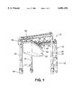
FIG. 1 is a perspective view of a gantry crane constructed in accordance with teachings of the present invention.
FIG. 2 is a schematic perspective view of the grappler of the crane of FIG. 1.
FIG. 3 is a schematic perspective view of the grappler of the crane of FIG. 1.
FIG. 4 is a schematic view of a grappler positioning system according to teachings of the invention.
FIG. 5 is a front view of a monitor having a line on the screen providing a reference for the grappler position relative to an edge of a container displayed on the monitor.
DETAILED DESCRIPTION OF THE DRAWINGS
Now turning to the Figures, wherein like numerals designate like components, FIG. 1 illustrates a mobile gantry crane 10 having a grappler positioning system according to the invention. Generally, the crane 10 has a frame 15 including four vertical columns 20, upper horizontal beams 25 fixed between the columns 20, and a pair of trolleys 30 movably mounted to the respective beams 25 for transverse movement. The crane 10 includes a plurality of wheels 35 on which the crane 10 is rollably drivable.
For lockably engaging and lifting a container 40, the crane 10 has a lifting mechanism or grappler 45 which is movably suspended from the trolleys 30. The grappler 45 generally includes a body 50 having a container-grasping mechanism, such as four male twistlocks 55 (FIGS. 2, 3) mounted in a rectangular pattern corresponding to positions of locking holes 60 (FIG. 2) located at the top corners of a standard shipping container 40. The twistlocks 55 enable the grappler 45 to lockably engage a container 40 for lifting, as described in greater detail below. Although the body 50 of the grappler 45 is illustrated in FIG. 1 as being rectangular, the body 50 can of any suitable shape such that the twistlocks 55 are at the desired relative positions. The grappler 45 is generally aligned along a longitudinal axis which extends from front to back of the crane 10.
In other possible embodiments, the grappler 45 may have grappler arms (not shown) of a type which are generally known. When the grappler 45 is properly landed and/or aligned on a container, the grappler arms are pivoted to grab the container for lifting. Such arms may be provided in addition to, or in lieu of, the twistlocks 55.
In an embodiment illustrated in FIG. 1, the grappler 45 is suspended from the trolleys 30 by wire ropes 65. On the wire ropes 65, the grappler 45 is selectively lifted and lowered. The wire ropes 65 are coilably paid out and retracted from rotatable hoisting drums mounted to the respective trolleys 30. These wire ropes 65 pass around rotatable sheaves 70 fixed to the grappler 45. When the wire ropes 65 are moved, the suspended grappler 45 is caused to move vertically lower or higher. In another embodiment (not illustrated), the grappler 45 is fixed to the trolleys 30, and the beams 25 are movably mounted to engage tracks extending along the columns 20. The grappler 45 is vertically movable by operably driving the beams 25 along the columns 20.
The trolleys 30 are movable in a side-to-side manner, moving the suspended grappler 45 accordingly. The trolleys 30 include rollers to facilitate traversible travel of the trolleys 30 along the respective horizontal beams 25 of the frame 10. In an embodiment, the suspended grappler 45 may be movably mounted for forward or rearward movement along a longitudinal beam extending between the trolleys 30 as well.
Still referring to FIG. 1, the gantry crane 10 includes a cab 75 mounted to the frame 15 to accommodate an operator. The cab 75 contains controls for driving the crane 10 and positioning the grappler 45. The operator can view the grappler and container to be lifted through windows in the cab 75.
The grappler 45 must be properly positioned and lowered to engage a container 40 to be lifted. Specifically, the grappler 45 must be carefully landed on an upper surface 41 of the container 40 in corresponding alignment. For example, in the embodiment of FIGS. 2 and 3, the grappler must be lowered while the four twistlocks 55 are respectively aligned with the locking holes 60 located in the top of the container 40. When the grappler 45 is lowered in proper alignment onto the top of the container 40, the twistlocks 55 are matably received into the locking holes 60. The twistlocks 55 are then actuated to rotate within the holes 60, lockably securing the grappler 45 to the container 40 in a generally known manner for lifting and handling.
According to the invention, a grappler positioning system is provided to assist in positioning a grappler as it is lowered to engage a container. The system includes video devices in combination with position sensors that provide information to assist in properly guiding the grappler relative to the container.
In particular, referring to FIGS. 2 and 3, at least two corner video devices 100 are mounted to the grappler 45 at respective corners of the grappler body 50. More specifically, in the embodiment shown in FIGS. 2 and 3, the video devices 100 are respectively mounted near at least two of the twistlocks 55. These video devices 100 are aimed generally downwardly to view the container 40 below, and particularly to view respective corner areas of the container 40 having the locking holes 60 disposed therein. The video devices 100 deliver images which are displayed in the cab 75.
The image provided by each video device 100 enables the operator to adjust the side-to-side or front-to-back position of the grappler 45 relative to the container 40 as the grappler 45 is lowered to properly align the respective twistlocks 55 with the corresponding locking holes 60. By providing at least two of the corner video devices 100, the operator is able to align two corners of the grappler 45 relative to the container 40, thereby also aligning corners of the grappler not equipped with video devices 100. Embodiments are possible, however, wherein more than two corners of the grappler 45 are equipped with video devices 100.
In an embodiment of the invention, as illustrated in FIGS. 2-3, a pointer 102 is mounted to the grappler body 50 near a respective one of the video devices 100. The pointer 102 is an elongated member which extends downwardly. At least a tip portion of the pointer 102 is viewable by one of said video devices 100 to provide a point of reference of the location of an edge of the grappler 45. As the grappler 45 is maneuvered relative to a container 40, the position of the pointer 102 helps an operator gauge the position of the grappler 45. In the illustrated embodiment, the pointer 102 is disposed along the side of the container when the grappler is lowered to land on top of the container. The pointer 102 may be pivotably mounted and/or constructed of a resilient material so that the pointer 102 is not damaged if brought into contact against the container 40.
In an embodiment of the invention, as illustrated in FIG. 3, a distal video device 105 is mounted to a side of the grappler 45 opposite the cab 75 to provide a downward view of the container 40. In an embodiment, this distal video device 105 has a wide angle or "fisheye" lens. The distal video device 105 provides a view which assists the operator to align the side of the grappler 45 with the side of the container 40.
Each of the video devices 100, 105 delivers a video signal via a cable 106 (FIG. 3) which is displayed in the cab 75 on one or more monitors 110, as illustrated in FIG. 4. Signals from the video devices 100, 105 are delivered to a processor 111, which delivers a signal to the monitor 110, which may be a CRT, LCD screen, or some other known type of display. In an embodiment, a single monitor 110 is operable display the view from a selected one of the video devices 100, 105, and a switch 115 is provided to permit selection between the various video devices 100, 105. In another embodiment, multiple video monitors 110 are provided, displaying views from the respective video devices 100, 105. In a still further embodiment, a monitor 110 can have a split display to show images from of a plurality of the video devices 100, 105.
In the embodiment which includes the distal video device 105, the monitor 110 may be adapted to indicate a visual reference of the position of the grappler relative to the container 40. More specifically, illustrated in FIG. 5 is the monitor 110 displaying the view from the distal video device 105 (FIG. 3) directed downwardly from the grappler 45. The monitor 110 has a screen 112 across which has a line 113 is provided. The line 113 is to represents an orientation of the side of the grappler 45. As illustrated in FIG. 5, an edge 240 of the container 40 is displayed on the screen 112 as viewed from the distal video device 105. The line 113 is positioned on the screen 112 such that when the line 113 overlies or otherwise corresponds to the image of the edge 240 of the container 40, the grappler 45 is properly oriented with the edge 240 of the container 40. The line 113 can be generated electronically and displayed as an overlay on the screen 112, or the line 113 can be physically applied to the screen 112, such as by tape. With the monitor 110 of the embodiment shown in FIG. 5, an operator can detect the position the grappler 45 relative to the displayed edge 240 container 40 and accordingly adjust the position of the grappler to align the line 113 with the edge 240. The foregoing procedure can also be used to align the grappler 45 with a trailer for typical bottom picking applications with the grappler arms (not shown).
Also illustrated in FIGS. 2 and 3, for measuring a distance h between the grappler 45 and an upper surface 42 of the container 40, an embodiment of the invention further includes at least two height sensors 120 are mounted to the grappler 45. The height sensors 120 are spaced from each other so that a tilting of the grappler 45 can be detected by a difference in the heights measured by the respective height sensors 120. Particularly, in an embodiment, a pair of height sensors 120 is mounted to an underside of the grappler 45 such that the sensors 120 are spaced from each other in a longitudinal direction.
Preferably, the height sensors 120 operate by with ultrasonic waves. As illustrated in FIG. 2, each of the height sensors 120 emits ultrasonic waves 125 which are reflected from the upper surface 42 of the container 40. By detecting the time for the reflected waves to return to the sensor, a generally downward distance h is measured between a respective one of the height sensors 120 and the upper surface 41 of the container 40. A distance measurement corresponding to each of the sensors 120 is displayed on a readout 130 in the cab 75, as shown in FIG. 4.
In an embodiment, the processor 111 detects when the height sensors 120 are measuring substantially different respective heights, assuming a tilted orientation of the grappler 45 relative to the container 40. The processor 111 then actuates a warning indicator 135 to alert the operator to the tilted condition or to display the degree of tilt.
In a further embodiment, the system includes a plurality of alignment sensors 140 mounted to respective sides of the grappler 45, as shown in FIGS. 2 and 3. Each of the alignment sensors is operable to detect the relative positions of a corresponding edge of the container 40 below. Preferably, the system includes four alignment sensors 140 mounted at the four respective sides of the grappler 45. The sensors 140 are connected to actuate respective indicators in the cab 75 for example, lights 145 as shown in FIG. 4, when the sides of the grappler 45 are properly aligned vertically above the corresponding sides of the container 40. When the lights 145 indicate that the grappler 45 is aligned vertically above the container 40, as indicated by the dashed lines 146 in FIG. 3, the operator can simply lower the grappler 45 to a properly aligned landing atop the container 40.
The video devices 100 and/or 105 are preferably video cameras which produce a real-time image. Alternatively, the video devices 100 and/or 105 may be some other sort of image generating device such as infrared cameras or appropriate image-mapping transducers.
In an embodiment, the grappler positioning system of the invention may be automated so that the grappler 45 is automatically guided and lowered in proper alignment for engaging the container 40. In such an embodiment, the processor 111 is programmed determine the position of the grappler 45 relative to the container 40 from the signals delivered from the video devices 100, 105 and/or sensors 120, 140. Furthermore, the processor 111 then controllably adjusts the position of trolleys 30 and the motion of the hoist means to carefully lower the grappler 45 relative to a container 40 with proper alignment of the twistlocks 55.
Although the invention is described herein in connection with certain preferred embodiments, it is recognized that various changes and modifications to the invention will be apparent to those skilled in the art. Such changes and modifications may be made without departing from the spirit and scope of the invention. Accordingly, the appended claims are intended to cover all such changes and modifications.

Claims (23)

What is claimed is:
1. A gantry crane having frame and a vertically movable grappler supported by the frame, the grappler being operable to engage and lift a container, the grappler having a plurality of twistlocks positioned to engage locking holes in a container, the gantry crane also having a grappler positioning system including:
at least two video devices mounted to the grappler at respective corners of the grappler near the twistlocks;
at least one monitor operable to display a video image from at least one of the video devices;
a plurality of alignment sensors, each alignment sensor being mounted near a respective side of the grappler between two of the twistlocks for sensing a relative position of a respective side of a container vertically below; and
an indicator actuatable by a respective one of the alignment sensors to indicate when the respective side of the grappler is aligned vertically over the side of the container.
2. A crane according to claim 1, wherein the alignment sensors are ultrasonic sensors.
3. A crane according to claim 1, further comprising a switch operable to selectively display a view from one of said video devices on said video monitor.
4. A crane according to claim 1, wherein at least one of said video devices is a video camera.
5. A crane according to claim 1, wherein at least one of said video devices is an infrared camera.
6. A crane according to claim 1, further comprising a plurality of height sensors mounted to the grappler sensing respective distances of the grappler from an upper surface of the container and a height display located in the cab displaying a height detected by the height sensors.
7. A crane according to claim 6, wherein the height sensors are ultrasonic sensors.
8. A crane according to claim 1, further comprising a distal video device mounted to a side of the grappler opposite the cab and directed generally downwardly to provide a view of the grappler and container.
9. A crane according to claim 8, wherein the distal video device has a wide angle lens.
10. A crane according to claim 8 wherein the distal video device is mounted to the grappler generally at a midpoint in a longitudinal direction between the corners of the grappler.
11. A crane according to claim 1, further comprising a pointer mounted to extend generally downwardly from the grappler so that a portion of the pointer is viewable by one of said video devices.
12. A grappler guidance system for a gantry crane of a type having a frame supporting a vertically movable grappler which is operable to grasp and lift a container, the grappler having a plurality of twistlocks positioned to engage locking holes at upper corners of a standard container, the gantry crane further having a grappler positioning system including:
at least two corner video devices mounted to the grappler at near respective twistlocks;
a distal video device mounted to a side of the grappler opposite the cab and directed generally downwardly to provide a view of an edge of the container;
at least one monitor operable to display a video image from at least one of the video devices;
a plurality of alignment sensors, each alignment sensor being mounted near a respective side of the grappler between two of the twistlocks for sensing a position of a respective side of a container vertically below relative to the side of the grappler;
an indicator actuatable by a respective one of the alignment sensors to indicate when the respective side of the grappler is aligned vertically over the side of the container
a plurality of height sensors mounted to the grappler, each of the height sensors sensing a respective distance between the grappler and an upper surface of the container; and
a readout located in the cab displaying a height detected by the height sensors.
13. A grappler guidance system according to claim 12, wherein the alignment sensors are ultrasonic sensors.
14. A grappler guidance system according to claim 12, further comprising a switch operable to selectively display a view from one of said video devices on said video monitor.
15. A grappler guidance system according to claim 12, wherein at least one of said video devices is a video camera.
16. A grappler guidance system according to claim 12, wherein at least one of said video devices is an infrared camera.
17. A grappler guidance system according to claim 12, wherein the height sensors are ultrasonic sensors.
18. A grappler guidance system according to claim 12, wherein the distal video device has a wide angle lens.
19. A grappler guidance system according to claim 12, wherein the distal video device is mounted to the grappler generally at a midpoint in a longitudinal direction between the corners of the grappler.
20. A grappler guidance system according to claim 12, wherein the height sensors are located generally near opposite longitudinal ends of the grappler.
21. A grappler guidance system according to claim 12, further comprising a pointer mounted to extend from the grappler so that a portion of the pointer is viewable by one of said video devices.
22. A crane according to claim 1, wherein said monitor includes a screen for displaying said video image and a line extending across the screen at a position representing an orientation of the grappler such that the grappler is aligned when said line corresponds to an edge of the container as displayed on the screen.
23. A grappler guidance system according to claim 12, wherein said monitor includes a screen for displaying said video image and a line extending across the screen at a position representing an orientation of the grappler such that the grappler is aligned when said line corresponds to an edge of the container as displayed on the screen.
US09/073,331 1998-05-06 1998-05-06 Grappler guidance system for a gantry crane Expired - Lifetime US6081292A (en)

Priority Applications (2)

Application Number Priority Date Filing Date Title
US09/073,331 US6081292A (en) 1998-05-06 1998-05-06 Grappler guidance system for a gantry crane
CA002327334A CA2327334C (en) 1998-05-06 1999-04-16 Grappler guidance system for a gantry crane

Applications Claiming Priority (1)

Application Number Priority Date Filing Date Title
US09/073,331 US6081292A (en) 1998-05-06 1998-05-06 Grappler guidance system for a gantry crane

Publications (1)

Publication Number Publication Date
US6081292A true US6081292A (en) 2000-06-27

Family

ID=22113102

Family Applications (1)

Application Number Title Priority Date Filing Date
US09/073,331 Expired - Lifetime US6081292A (en) 1998-05-06 1998-05-06 Grappler guidance system for a gantry crane

Country Status (2)

Country Link
US (1) US6081292A (en)
CA (1) CA2327334C (en)

Cited By (39)

* Cited by examiner, † Cited by third party
Publication number Priority date Publication date Assignee Title
US20020024598A1 (en) * 2000-07-25 2002-02-28 Satoshi Kunimitsu Detecting system for container's location
US20030015489A1 (en) * 2001-07-18 2003-01-23 Koji Uchida Crane and method for controlling the crane
US6968963B1 (en) 2002-07-09 2005-11-29 Mi-Jack Products, Inc. Grappler control system for a gantry crane
US20050281644A1 (en) * 2002-11-07 2005-12-22 Siemens Aktiengesellschaft Container crane, and method of determining and correcting a misalignment between a load-carrying frame and a transport vehicle
US20060102578A1 (en) * 2004-08-03 2006-05-18 Mi-Jack Products, Inc. Variable-speed load-dependent drive and hoist system
US20090314574A1 (en) * 2008-06-20 2009-12-24 Holzman Malcolm Movable acoustic shell assembly
ES2345228A1 (en) * 2008-03-18 2010-09-17 GAMESA INNOVATION & TECHNOLOGY, S.L. Safe hoist (Machine-translation by Google Translate, not legally binding)
US20100268366A1 (en) * 2007-11-29 2010-10-21 Airbus Operations Gmbh Diagnosis System
US20110000866A1 (en) * 2007-09-20 2011-01-06 Posco Apparatus for Controlling the Position of Crane Tong According to Slab Bending and the Method Thereof
US20110155683A1 (en) * 2009-12-24 2011-06-30 Korea Advanced Institute Of Science And Technology Crane spreader and method for automatically landing the same
CN102145859A (en) * 2011-02-15 2011-08-10 上海海事大学 Double-lifting-appliance bridge crane adopting ultrasonic sensor and positioning method thereof
US20110272376A1 (en) * 2010-05-10 2011-11-10 Korea Advanced Institute Of Science And Technology Trolley assembly for a crane and a crane therewith
CN102616658A (en) * 2012-03-27 2012-08-01 三一集团有限公司 Box control system for stacking machine
CN102795546A (en) * 2012-08-27 2012-11-28 三一集团有限公司 Method for controlling lifting appliance
CN103171995A (en) * 2011-12-20 2013-06-26 三一集团有限公司 System for controlling descending speed of spreader and stacking machine
DE102012003650A1 (en) * 2012-02-24 2013-08-29 recognitec Gesellschaft für digitale Bildverarbeitung mbH Method for controlled vertical lifting of standard container with container base, involves generating signal, in case of correspondence of termination criterion, so that further lifting of container is directly or indirectly closed
US20140079528A1 (en) * 2007-03-26 2014-03-20 Mi-Jack Products, Inc. Inline Terminal System
WO2014169096A1 (en) * 2013-04-12 2014-10-16 Dana Limited Device and control method for container locking
US20150148962A1 (en) * 2013-11-25 2015-05-28 Liebherr-Werk Nenzing Gmbh Method for controlling the fill volume of a grapple
US20150203334A1 (en) * 2014-01-17 2015-07-23 Mi-Jack Products, Inc. Crane Trolley and Hoist Position Homing and Velocity Synchronization
US20150232304A1 (en) * 2012-09-17 2015-08-20 Areva Wind Gmbh Lifter and method for handling a rotor blade, rotor blade for a wind generator and method for marking a rotor blade, system comprising a lifter and a rotor blade
EP2932823A1 (en) * 2014-04-17 2015-10-21 John Deere Forestry OY Material manipulating device, work vehicle and method
WO2016107979A1 (en) * 2014-12-31 2016-07-07 Konecranes Global Corporation Apparatus, methods, computer program, and collection for generating image data of load stack
USD764737S1 (en) * 2014-04-04 2016-08-23 Konecranes Global Corporation Gantry crane
US9611126B2 (en) * 2013-08-12 2017-04-04 Abb Schweiz Ag Method and system for automatically landing containers on a landing target using a container crane
US20170267501A1 (en) * 2014-08-26 2017-09-21 C. Steinweg-Handelsveem B.V. Device and method for loading a sea container with an elongated heavy product or a row of heavy products
EP3296247A1 (en) * 2016-09-14 2018-03-21 Siemens Aktiengesellschaft Detection of locking devices
US20180229978A1 (en) * 2013-04-11 2018-08-16 Liebherr-Components Biberach Gmbh Remote-controlled crane
WO2018224408A1 (en) * 2017-06-08 2018-12-13 Konecranes Global Corporation Automatically guided lifting gantry device for containers and method for operating such a lifting gantry device
CN109384150A (en) * 2017-08-03 2019-02-26 南通通镭软件有限公司 The container tapered end framing of automated handling slings method with anti-
CN109552899A (en) * 2018-12-23 2019-04-02 江苏正鼎智能装备有限公司 A kind of track type container tipper
US20190337773A1 (en) * 2016-12-15 2019-11-07 China University Of Mining And Technology Apparatus and method for measuring rotational angle of sinking platform
JP2020132361A (en) * 2019-02-20 2020-08-31 株式会社三井E&Sマシナリー Crane operation support system and operation support method
WO2020226739A1 (en) * 2019-05-07 2020-11-12 Tulsa Winch, Inc. Load moment indicator
US20210245954A1 (en) * 2014-05-29 2021-08-12 Kabushiki Kaisha Toshiba Cargo handling apparatus and method
US11472677B2 (en) * 2018-11-07 2022-10-18 Beijing Tusen Zhitu Technology Co., Ltd. Ship unloading control system, ship loading control system, and related systems and apparatuses
US11562456B2 (en) * 2018-11-07 2023-01-24 Beijing Tusen Zhitu Technology Co., Ltd. Intelligent port control system and related systems and apparatuses
EP4349764A1 (en) * 2022-10-07 2024-04-10 Hans Künz GmbH Crane
US11972501B2 (en) 2018-11-07 2024-04-30 Beijing Tusen Zhitu Technology Co., Ltd. Intelligent port control system and related systems and apparatuses

Citations (38)

* Cited by examiner, † Cited by third party
Publication number Priority date Publication date Assignee Title
US2355086A (en) * 1943-10-27 1944-08-08 Walter B Lang Marine salvage device
US3367299A (en) * 1966-08-01 1968-02-06 Navy Usa Underwater recovery vehicle
DE2053590A1 (en) * 1970-10-31 1972-05-04 Siemens Ag Loading device for containers
US3858728A (en) * 1974-01-11 1975-01-07 Midland Ross Corp Radio control crane and spreader system for handling containers
US3881608A (en) * 1972-08-17 1975-05-06 Conrad Starke B V Bridge crane
US3904234A (en) * 1973-10-15 1975-09-09 Stanford Research Inst Manipulator with electromechanical transducer means
US3972420A (en) * 1971-09-20 1976-08-03 Stock Equipment Company Crane apparatus
DE2642373A1 (en) * 1975-09-23 1977-03-31 Johan Van Stijn B V CRANE WITH CLOSED TELEVISION
DE2746794A1 (en) * 1976-10-20 1978-05-03 Hitachi Ltd DEVICE FOR POSITIONING A SPREADING FRAME FOR THE AUTOMATIC DETECTION AND HANDLING OF AN ELEMENTED GOOD
US4151983A (en) * 1971-09-20 1979-05-01 Stock Equipment Company Crane grab apparatus
US4172685A (en) * 1976-10-22 1979-10-30 Hitachi, Ltd. Method and apparatus for automatic operation of container crane
US4177964A (en) * 1978-09-08 1979-12-11 General Dynamics Corporation Docking system for space structures
US4245271A (en) * 1979-05-18 1981-01-13 Gwin Steve W Crane system or cargo containers
US4260187A (en) * 1979-03-23 1981-04-07 Nasa Terminal guidance sensor system
US4358145A (en) * 1979-05-09 1982-11-09 Scal Sweden Ab Lifting device for container
GB2099255A (en) * 1981-05-15 1982-12-01 Atomic Energy Authority Uk A system and a method for detecting the position of an object
GB2113179A (en) * 1982-01-19 1983-08-03 John Coltman Improvements in or relating to container spreaders
US4419079A (en) * 1980-07-23 1983-12-06 Avions Marcel Dassault-Breguet Aviation Aircraft piloting aid system
US4423998A (en) * 1980-07-24 1984-01-03 Fujitsu Fanuc Ltd. Gripping device
US4460302A (en) * 1980-05-14 1984-07-17 Commissariat A L'energie Atomique Handling equipment comprising a telescopic supporting assembly carrying a motorized orientation support for at least one articulated slave arm
US4657728A (en) * 1983-04-13 1987-04-14 Commissariat A L'energie Atomique Machine for examining a nuclear reactor fuel assembly
US4715772A (en) * 1985-05-30 1987-12-29 Kabushiki Kaisha Fujikoshi Apparatus for automatic glazing of cars
EP0254192A2 (en) * 1986-07-19 1988-01-27 T.E.C. Computer Gmbh Method and device for driving vehicles and/or increasing the operators active and passive safety
US4725826A (en) * 1987-01-16 1988-02-16 Hunter Bryan D Manipulator grip slip sensor
US4843708A (en) * 1987-04-23 1989-07-04 Nissan Motor Co., Ltd. Assembly method for component parts and system
EP0342655A2 (en) * 1988-05-18 1989-11-23 Tax Ingenieurgesellschaft Mbh Crane installation for a container
US4884681A (en) * 1988-10-28 1989-12-05 Ethicon, Inc. Retainer for surgical sutures
EP0347784A1 (en) * 1988-06-22 1989-12-27 Outokumpu Oy Automatic charging member
US4932541A (en) * 1989-04-24 1990-06-12 Calspan Corporation Stabilized shipboard crane
US5067013A (en) * 1989-12-08 1991-11-19 Kone Oy Procedure and apparatus for locating a container for lifting
US5114295A (en) * 1989-03-13 1992-05-19 Sea Flats Aktiebolag Container handling wagon
US5154561A (en) * 1990-04-11 1992-10-13 Lee Donald E Automated all-weather cargo transfer system
US5392935A (en) * 1992-10-06 1995-02-28 Obayashi Corporation Control system for cable crane
US5428344A (en) * 1992-04-06 1995-06-27 Curry; John R. Crane hoist safety deactivator
US5481248A (en) * 1993-03-11 1996-01-02 Kruh; Brian A. Overhead cranes having collision avoidance capabilities
US5491549A (en) * 1992-11-03 1996-02-13 Siemens Aktiengesellschaft Apparatus for acquiring pendulum oscillations of crane loads using measurement techniques
US5649636A (en) * 1996-02-08 1997-07-22 Mi-Jack Products Inc. Adjustable load lifting device
US5754672A (en) * 1994-11-30 1998-05-19 Mitsubishi Jukogyo Kabushiki Kaisha Deflection detective device for detecting the deflection of suspended cargo

Patent Citations (40)

* Cited by examiner, † Cited by third party
Publication number Priority date Publication date Assignee Title
US2355086A (en) * 1943-10-27 1944-08-08 Walter B Lang Marine salvage device
US3367299A (en) * 1966-08-01 1968-02-06 Navy Usa Underwater recovery vehicle
DE2053590A1 (en) * 1970-10-31 1972-05-04 Siemens Ag Loading device for containers
US4151983A (en) * 1971-09-20 1979-05-01 Stock Equipment Company Crane grab apparatus
US3972420A (en) * 1971-09-20 1976-08-03 Stock Equipment Company Crane apparatus
US3881608A (en) * 1972-08-17 1975-05-06 Conrad Starke B V Bridge crane
US3904234A (en) * 1973-10-15 1975-09-09 Stanford Research Inst Manipulator with electromechanical transducer means
US3858728A (en) * 1974-01-11 1975-01-07 Midland Ross Corp Radio control crane and spreader system for handling containers
DE2642373A1 (en) * 1975-09-23 1977-03-31 Johan Van Stijn B V CRANE WITH CLOSED TELEVISION
DE2746794A1 (en) * 1976-10-20 1978-05-03 Hitachi Ltd DEVICE FOR POSITIONING A SPREADING FRAME FOR THE AUTOMATIC DETECTION AND HANDLING OF AN ELEMENTED GOOD
US4139107A (en) * 1976-10-20 1979-02-13 Hitachi, Ltd. Spreader positioning apparatus for automatically grasping a handling article
US4172685A (en) * 1976-10-22 1979-10-30 Hitachi, Ltd. Method and apparatus for automatic operation of container crane
US4177964A (en) * 1978-09-08 1979-12-11 General Dynamics Corporation Docking system for space structures
US4260187A (en) * 1979-03-23 1981-04-07 Nasa Terminal guidance sensor system
US4358145A (en) * 1979-05-09 1982-11-09 Scal Sweden Ab Lifting device for container
US4245271A (en) * 1979-05-18 1981-01-13 Gwin Steve W Crane system or cargo containers
US4460302A (en) * 1980-05-14 1984-07-17 Commissariat A L'energie Atomique Handling equipment comprising a telescopic supporting assembly carrying a motorized orientation support for at least one articulated slave arm
US4419079A (en) * 1980-07-23 1983-12-06 Avions Marcel Dassault-Breguet Aviation Aircraft piloting aid system
US4423998A (en) * 1980-07-24 1984-01-03 Fujitsu Fanuc Ltd. Gripping device
GB2099255A (en) * 1981-05-15 1982-12-01 Atomic Energy Authority Uk A system and a method for detecting the position of an object
GB2113179A (en) * 1982-01-19 1983-08-03 John Coltman Improvements in or relating to container spreaders
US4657728A (en) * 1983-04-13 1987-04-14 Commissariat A L'energie Atomique Machine for examining a nuclear reactor fuel assembly
US4715772A (en) * 1985-05-30 1987-12-29 Kabushiki Kaisha Fujikoshi Apparatus for automatic glazing of cars
EP0254192A2 (en) * 1986-07-19 1988-01-27 T.E.C. Computer Gmbh Method and device for driving vehicles and/or increasing the operators active and passive safety
US4725826A (en) * 1987-01-16 1988-02-16 Hunter Bryan D Manipulator grip slip sensor
US4843708A (en) * 1987-04-23 1989-07-04 Nissan Motor Co., Ltd. Assembly method for component parts and system
US5048703A (en) * 1988-05-18 1991-09-17 Tax Ingenieurgesellschaft Mbh Container crane installation
EP0342655A2 (en) * 1988-05-18 1989-11-23 Tax Ingenieurgesellschaft Mbh Crane installation for a container
EP0347784A1 (en) * 1988-06-22 1989-12-27 Outokumpu Oy Automatic charging member
US4884681A (en) * 1988-10-28 1989-12-05 Ethicon, Inc. Retainer for surgical sutures
US5114295A (en) * 1989-03-13 1992-05-19 Sea Flats Aktiebolag Container handling wagon
US4932541A (en) * 1989-04-24 1990-06-12 Calspan Corporation Stabilized shipboard crane
US5067013A (en) * 1989-12-08 1991-11-19 Kone Oy Procedure and apparatus for locating a container for lifting
US5154561A (en) * 1990-04-11 1992-10-13 Lee Donald E Automated all-weather cargo transfer system
US5428344A (en) * 1992-04-06 1995-06-27 Curry; John R. Crane hoist safety deactivator
US5392935A (en) * 1992-10-06 1995-02-28 Obayashi Corporation Control system for cable crane
US5491549A (en) * 1992-11-03 1996-02-13 Siemens Aktiengesellschaft Apparatus for acquiring pendulum oscillations of crane loads using measurement techniques
US5481248A (en) * 1993-03-11 1996-01-02 Kruh; Brian A. Overhead cranes having collision avoidance capabilities
US5754672A (en) * 1994-11-30 1998-05-19 Mitsubishi Jukogyo Kabushiki Kaisha Deflection detective device for detecting the deflection of suspended cargo
US5649636A (en) * 1996-02-08 1997-07-22 Mi-Jack Products Inc. Adjustable load lifting device

Cited By (66)

* Cited by examiner, † Cited by third party
Publication number Priority date Publication date Assignee Title
US20020024598A1 (en) * 2000-07-25 2002-02-28 Satoshi Kunimitsu Detecting system for container's location
US20030015489A1 (en) * 2001-07-18 2003-01-23 Koji Uchida Crane and method for controlling the crane
US6880712B2 (en) * 2001-07-18 2005-04-19 Mitsubishi Heavy Industries, Ltd. Crane and method for controlling the crane
US6968963B1 (en) 2002-07-09 2005-11-29 Mi-Jack Products, Inc. Grappler control system for a gantry crane
US20050281644A1 (en) * 2002-11-07 2005-12-22 Siemens Aktiengesellschaft Container crane, and method of determining and correcting a misalignment between a load-carrying frame and a transport vehicle
US7289876B2 (en) * 2002-11-07 2007-10-30 Siemens Aktiengesellschaft Container crane, and method of determining and correcting a misalignment between a load-carrying frame and a transport vehicle
US20060102578A1 (en) * 2004-08-03 2006-05-18 Mi-Jack Products, Inc. Variable-speed load-dependent drive and hoist system
US7353959B2 (en) 2004-08-03 2008-04-08 Mi-Jack Products, Inc. Variable-speed load-dependent drive and hoist system
US20140079528A1 (en) * 2007-03-26 2014-03-20 Mi-Jack Products, Inc. Inline Terminal System
US20110000866A1 (en) * 2007-09-20 2011-01-06 Posco Apparatus for Controlling the Position of Crane Tong According to Slab Bending and the Method Thereof
US8527093B2 (en) * 2007-09-20 2013-09-03 Posco Apparatus for controlling the position of crane tong according to slab bending and the method thereof
US20100268366A1 (en) * 2007-11-29 2010-10-21 Airbus Operations Gmbh Diagnosis System
US8972034B2 (en) * 2007-11-29 2015-03-03 Airbus Operations Gmbh Diagnosis system
ES2345228A1 (en) * 2008-03-18 2010-09-17 GAMESA INNOVATION & TECHNOLOGY, S.L. Safe hoist (Machine-translation by Google Translate, not legally binding)
US7815011B2 (en) * 2008-06-20 2010-10-19 Holzman Moss Architecture, Llp Movable acoustic shell assembly
US20090314574A1 (en) * 2008-06-20 2009-12-24 Holzman Malcolm Movable acoustic shell assembly
US20110155683A1 (en) * 2009-12-24 2011-06-30 Korea Advanced Institute Of Science And Technology Crane spreader and method for automatically landing the same
US20110272376A1 (en) * 2010-05-10 2011-11-10 Korea Advanced Institute Of Science And Technology Trolley assembly for a crane and a crane therewith
CN102145859A (en) * 2011-02-15 2011-08-10 上海海事大学 Double-lifting-appliance bridge crane adopting ultrasonic sensor and positioning method thereof
CN103171995A (en) * 2011-12-20 2013-06-26 三一集团有限公司 System for controlling descending speed of spreader and stacking machine
CN103171995B (en) * 2011-12-20 2016-08-10 三一集团有限公司 A kind of suspender decrease speed control system and stacker
DE102012003650B4 (en) * 2012-02-24 2014-02-13 recognitec Gesellschaft für digitale Bildverarbeitung mbH Method and device for supervised vertical lifting of a standard container
DE102012003650A1 (en) * 2012-02-24 2013-08-29 recognitec Gesellschaft für digitale Bildverarbeitung mbH Method for controlled vertical lifting of standard container with container base, involves generating signal, in case of correspondence of termination criterion, so that further lifting of container is directly or indirectly closed
CN102616658B (en) * 2012-03-27 2014-09-10 三一集团有限公司 Box control system for stacking machine
CN102616658A (en) * 2012-03-27 2012-08-01 三一集团有限公司 Box control system for stacking machine
CN102795546B (en) * 2012-08-27 2014-10-15 三一集团有限公司 Method for controlling lifting appliance
CN102795546A (en) * 2012-08-27 2012-11-28 三一集团有限公司 Method for controlling lifting appliance
US20150232304A1 (en) * 2012-09-17 2015-08-20 Areva Wind Gmbh Lifter and method for handling a rotor blade, rotor blade for a wind generator and method for marking a rotor blade, system comprising a lifter and a rotor blade
US9546080B2 (en) * 2012-09-17 2017-01-17 Areva Wind Gmbh Lifter and method for handling a rotor blade, rotor blade for a wind generator and method for marking a rotor blade, system comprising a lifter and a rotor blade
US10662033B2 (en) * 2013-04-11 2020-05-26 Liebherr Components Biberach Gmbh Remote-controlled crane
US20180229978A1 (en) * 2013-04-11 2018-08-16 Liebherr-Components Biberach Gmbh Remote-controlled crane
WO2014169096A1 (en) * 2013-04-12 2014-10-16 Dana Limited Device and control method for container locking
US9695022B2 (en) 2013-04-12 2017-07-04 Dana Limited Device and control method for container locking
US9611126B2 (en) * 2013-08-12 2017-04-04 Abb Schweiz Ag Method and system for automatically landing containers on a landing target using a container crane
US10099903B2 (en) * 2013-11-25 2018-10-16 Liebherr-Werk Nenzing Gmbh Method for controlling the fill volume of a grapple
US20150148962A1 (en) * 2013-11-25 2015-05-28 Liebherr-Werk Nenzing Gmbh Method for controlling the fill volume of a grapple
US9321614B2 (en) * 2014-01-17 2016-04-26 Mi-Jack Products, Inc. Crane trolley and hoist position homing and velocity synchronization
US20150203334A1 (en) * 2014-01-17 2015-07-23 Mi-Jack Products, Inc. Crane Trolley and Hoist Position Homing and Velocity Synchronization
US10196242B2 (en) * 2014-01-17 2019-02-05 Mi-Jack Products, Inc. Crane trolley and hoist position homing and velocity synchronization
USD764737S1 (en) * 2014-04-04 2016-08-23 Konecranes Global Corporation Gantry crane
EP2932823A1 (en) * 2014-04-17 2015-10-21 John Deere Forestry OY Material manipulating device, work vehicle and method
US20210245954A1 (en) * 2014-05-29 2021-08-12 Kabushiki Kaisha Toshiba Cargo handling apparatus and method
US20170267501A1 (en) * 2014-08-26 2017-09-21 C. Steinweg-Handelsveem B.V. Device and method for loading a sea container with an elongated heavy product or a row of heavy products
WO2016107979A1 (en) * 2014-12-31 2016-07-07 Konecranes Global Corporation Apparatus, methods, computer program, and collection for generating image data of load stack
US10336586B2 (en) 2014-12-31 2019-07-02 Konecranes Global Corporation Apparatus, methods, computer program, and collection for generating image data of load stack
CN107108184B (en) * 2014-12-31 2019-10-29 科尼全球公司 For generating device, method, computer readable storage medium and the external member of the image data that load stacks
CN107108184A (en) * 2014-12-31 2017-08-29 科尼全球公司 Device, method, computer program and external member for generating the view data that load is stacked
WO2018050365A1 (en) * 2016-09-14 2018-03-22 Siemens Aktiengesellschaft Detection of locking devices
US11745987B2 (en) 2016-09-14 2023-09-05 Siemens Aktiengesellschaft Detection of locking devices
EP3296247A1 (en) * 2016-09-14 2018-03-21 Siemens Aktiengesellschaft Detection of locking devices
CN109641729B (en) * 2016-09-14 2020-10-13 西门子股份公司 Detection of a locking device
CN109641729A (en) * 2016-09-14 2019-04-16 西门子股份公司 The detection of locking device
US20190337773A1 (en) * 2016-12-15 2019-11-07 China University Of Mining And Technology Apparatus and method for measuring rotational angle of sinking platform
US10870559B2 (en) * 2016-12-15 2020-12-22 China University Of Mining And Technology Apparatus and method for measuring rotational angle of sinking platform
US11702323B2 (en) 2017-06-08 2023-07-18 Konecranes Global Corporation Automatically guided lifting gantry device for containers and method for operating such a lifting gantry device
CN110691752B (en) * 2017-06-08 2021-11-23 科尼起重机全球公司 Automatically guided door lifting device for containers and method for operating such a door lifting device
CN110691752A (en) * 2017-06-08 2020-01-14 科尼起重机全球公司 Automatically guided door lifting device for containers and method for operating such a door lifting device
WO2018224408A1 (en) * 2017-06-08 2018-12-13 Konecranes Global Corporation Automatically guided lifting gantry device for containers and method for operating such a lifting gantry device
CN109384150A (en) * 2017-08-03 2019-02-26 南通通镭软件有限公司 The container tapered end framing of automated handling slings method with anti-
US11472677B2 (en) * 2018-11-07 2022-10-18 Beijing Tusen Zhitu Technology Co., Ltd. Ship unloading control system, ship loading control system, and related systems and apparatuses
US11562456B2 (en) * 2018-11-07 2023-01-24 Beijing Tusen Zhitu Technology Co., Ltd. Intelligent port control system and related systems and apparatuses
US11972501B2 (en) 2018-11-07 2024-04-30 Beijing Tusen Zhitu Technology Co., Ltd. Intelligent port control system and related systems and apparatuses
CN109552899A (en) * 2018-12-23 2019-04-02 江苏正鼎智能装备有限公司 A kind of track type container tipper
JP2020132361A (en) * 2019-02-20 2020-08-31 株式会社三井E&Sマシナリー Crane operation support system and operation support method
WO2020226739A1 (en) * 2019-05-07 2020-11-12 Tulsa Winch, Inc. Load moment indicator
EP4349764A1 (en) * 2022-10-07 2024-04-10 Hans Künz GmbH Crane

Also Published As

Publication number Publication date
CA2327334C (en) 2007-02-13
CA2327334A1 (en) 1999-11-11

Similar Documents

Publication Publication Date Title
US6081292A (en) Grappler guidance system for a gantry crane
WO1999057907A1 (en) Grappler guidance system for a gantry crane
US20080011554A1 (en) Movable sensor device on the loading means of a forklift
CN201198441Y (en) Apparatus for rectifying deviation of container gantry crane, laser aligning container truck and preventing hoist of container truck
JP6852178B2 (en) Offshore ship-to-ship lifting with target tracking assistance
US20050281644A1 (en) Container crane, and method of determining and correcting a misalignment between a load-carrying frame and a transport vehicle
JP2006312521A (en) Object position measuring device of container crane and automatic cargo handling device using this object position measuring device
US20110234389A1 (en) Guidance and collision warning device for forklift trucks
JPH10500091A (en) Luggage carrier target path correction method and luggage transport device
JPH0218295A (en) Container crane apparatus and operation thereof
US7123132B2 (en) Chassis alignment system
CN110540137B (en) Crane operation system based on multi-sensor fusion
DE102006012205A1 (en) Industrial truck with a lifting mast
US11691855B2 (en) Crane
US20220153559A1 (en) Crane, in particular mobile crane
JPH06312894A (en) Operating device for crane
EP1283814B1 (en) A spreader
JPH0971387A (en) Hoisted cargo position display device on crane truck
JP4298453B2 (en) Loading support device and monitoring device
GB2425520A (en) Vehicle positioning apparatus
JP2005289591A (en) Container spreader positioning display device
JP2016193778A (en) Crane operation support method and crane operation support device
MXPA00010824A (en) Grappler guidance system for a gantry crane
JP3421125B2 (en) Object position detection device
EP1681580A2 (en) Parking aid apparatus

Legal Events

Date Code Title Description
AS Assignment

Owner name: MI-JACK PRODUCTS, ILLINOIS

Free format text: ASSIGNMENT OF ASSIGNORS INTEREST;ASSIGNORS:LANIGAN, JACK, JR.;OLSON, DANIEL J.;REEL/FRAME:009971/0106;SIGNING DATES FROM 19990426 TO 19990427

STCF Information on status: patent grant

Free format text: PATENTED CASE

FEPP Fee payment procedure

Free format text: PAYOR NUMBER ASSIGNED (ORIGINAL EVENT CODE: ASPN); ENTITY STATUS OF PATENT OWNER: LARGE ENTITY

FPAY Fee payment

Year of fee payment: 4

FPAY Fee payment

Year of fee payment: 8

AS Assignment

Owner name: COLE TAYLOR BANK, ILLINOIS

Free format text: SECURITY AGREEMENT;ASSIGNOR:MI-JACK PRODUCTS, INC.;REEL/FRAME:022824/0242

Effective date: 20090508

FPAY Fee payment

Year of fee payment: 12