US6072383A - RFID tag having parallel resonant circuit for magnetically decoupling tag from its environment - Google Patents
RFID tag having parallel resonant circuit for magnetically decoupling tag from its environment Download PDFInfo
- Publication number
- US6072383A US6072383A US09/185,775 US18577598A US6072383A US 6072383 A US6072383 A US 6072383A US 18577598 A US18577598 A US 18577598A US 6072383 A US6072383 A US 6072383A
- Authority
- US
- United States
- Prior art keywords
- circuit
- transponder
- capacitor
- switch
- inductor
- Prior art date
- Legal status (The legal status is an assumption and is not a legal conclusion. Google has not performed a legal analysis and makes no representation as to the accuracy of the status listed.)
- Expired - Lifetime
Links
Images

Classifications
-
- H—ELECTRICITY
- H04—ELECTRIC COMMUNICATION TECHNIQUE
- H04B—TRANSMISSION
- H04B1/00—Details of transmission systems, not covered by a single one of groups H04B3/00 - H04B13/00; Details of transmission systems not characterised by the medium used for transmission
- H04B1/59—Responders; Transponders
-
- G—PHYSICS
- G06—COMPUTING; CALCULATING OR COUNTING
- G06K—GRAPHICAL DATA READING; PRESENTATION OF DATA; RECORD CARRIERS; HANDLING RECORD CARRIERS
- G06K7/00—Methods or arrangements for sensing record carriers, e.g. for reading patterns
- G06K7/10—Methods or arrangements for sensing record carriers, e.g. for reading patterns by electromagnetic radiation, e.g. optical sensing; by corpuscular radiation
- G06K7/10009—Methods or arrangements for sensing record carriers, e.g. for reading patterns by electromagnetic radiation, e.g. optical sensing; by corpuscular radiation sensing by radiation using wavelengths larger than 0.1 mm, e.g. radio-waves or microwaves
- G06K7/10316—Methods or arrangements for sensing record carriers, e.g. for reading patterns by electromagnetic radiation, e.g. optical sensing; by corpuscular radiation sensing by radiation using wavelengths larger than 0.1 mm, e.g. radio-waves or microwaves using at least one antenna particularly designed for interrogating the wireless record carriers
- G06K7/10336—Methods or arrangements for sensing record carriers, e.g. for reading patterns by electromagnetic radiation, e.g. optical sensing; by corpuscular radiation sensing by radiation using wavelengths larger than 0.1 mm, e.g. radio-waves or microwaves using at least one antenna particularly designed for interrogating the wireless record carriers the antenna being of the near field type, inductive coil
-
- G—PHYSICS
- G06—COMPUTING; CALCULATING OR COUNTING
- G06K—GRAPHICAL DATA READING; PRESENTATION OF DATA; RECORD CARRIERS; HANDLING RECORD CARRIERS
- G06K19/00—Record carriers for use with machines and with at least a part designed to carry digital markings
- G06K19/06—Record carriers for use with machines and with at least a part designed to carry digital markings characterised by the kind of the digital marking, e.g. shape, nature, code
- G06K19/067—Record carriers with conductive marks, printed circuits or semiconductor circuit elements, e.g. credit or identity cards also with resonating or responding marks without active components
- G06K19/07—Record carriers with conductive marks, printed circuits or semiconductor circuit elements, e.g. credit or identity cards also with resonating or responding marks without active components with integrated circuit chips
- G06K19/0723—Record carriers with conductive marks, printed circuits or semiconductor circuit elements, e.g. credit or identity cards also with resonating or responding marks without active components with integrated circuit chips the record carrier comprising an arrangement for non-contact communication, e.g. wireless communication circuits on transponder cards, non-contact smart cards or RFIDs
Definitions
- Tagging of articles for identification and/or theft protection is known. For instance, many articles are identified using a bar code comprising coded information which is read by passing the bar code within view of a scanner. Many articles also include a resonant transponder or resonant tag for use in theft detection and prevention. More recently, passive resonant tags which return unique or semi-unique identification codes have been developed. These tags typically include an integrated circuit (IC) which stores the identification code. Such "intelligent" tags provide information about an article or person with which the tag is associated which is detected in the zone of an interrogator or reader. The tags are desirable because they can be interrogated rapidly, and from a distance.
- U.S. Pat. No. 5,446,447 (Carney et al.)
- U.S. Pat. No. 5,430,441 Billley et al.
- U.S. Pat. No. 5,347,263 disclose three examples of such intelligent tags.
- Radio frequency identification (RFID) tags or cards generally include a resonant antenna circuit electrically connected to the IC.
- the IC is essentially a programmable memory for storing digitally encoded information.
- the interrogator transmit antenna
- an AC voltage is induced in the resonant antenna circuit of the tag, which is rectified by the IC to provide the IC with an internal DC voltage.
- the induced voltage increases.
- the internal DC voltage reaches a level that assures proper operation of the IC, the IC outputs its stored data.
- the IC creates a series of data pulses by switching in or out an extra capacitor or inductor across the antenna circuit for the duration of the pulse, which changes the resonant frequency of the tag, detuning the tag from the operational frequency. That is, the tag creates data pulses by detuning itself, which changes the amount of energy consumed by the tag.
- the interrogator detects the consumption of energy in its field and interprets the changes as data pulses.
- RFID tags or cards are known, there are still technical difficulties and limitations associated with the operation of such tags.
- One problem with attempting to read multiple RFID tags within an interrogation zone of the interrogator is that more than one tag may be activated by the interrogator at about the same time.
- the fields generated by one tag can disturb the fields generated by another tag.
- This problem of mutual inductance is especially significant for RFID tags which transmit their information by detuning, as described above.
- the effective reading distance for the tags drops and the modulation of the tag can become completely ineffective due to the fact that such modulation depends upon the tag being in resonance (or close to it).
- detuning caused by other tags can make the reading of stored information impossible or nearly impossible.
- an RFID transponder includes an integrated circuit for storing data and an inductor electrically connected to the integrated circuit.
- the inductor includes a first coil electrically connected to a second coil.
- a resonant capacitor is electrically connected to the integrated circuit and to at least one of the first and second coils, such that the resonant capacitor and the at least one connected coil have a first predetermined resonant frequency.
- a switch having a first position and a second position is provided for selectively allowing current to flow through the second coil.
- the switch When the switch is in the first position, exposure of the transponder to an external field at or near the first resonant frequency induces a voltage in the inductor and causes a first current to flow through the inductor in a first direction, thereby generating a local field.
- the switch When the switch is in the second position, exposure of the transponder to an external field at or near the first resonant frequency induces a voltage in the inductor and causes a first current to flow through the first coil in a first direction, thereby generating a first local field and a second current to flow through the second coil in a second, opposite direction, thereby generating a second local field.
- a sum of the first and second local fields approaches zero.
- This field canceling technique is feasible but has some disadvantages.
- the circuit implementation uses a three turn coil in series with a one turn coil which requires approximately three times greater current flow in the one turn coil. This is difficult to achieve, especially when a low impedance switch must be connected across the one turn coil.
- the field canceling technique also limits the flexibility of the design because the mutual coupling between the coils is critical, and must be adjusted empirically.
- the present invention provides a transponder which includes a first inductor and a second inductor connected in series, a first capacitor, a second capacitor, and a switch.
- a first resonant circuit and a second circuit are formed in the transponder.
- the first resonant circuit is formed from a parallel connection of the series connected first and second inductors, and the first capacitor.
- the first resonant circuit has a primary resonant frequency.
- the second circuit is formed from a series connection of the second capacitor and the switch.
- the series connection of the second capacitor and the switch is connected in parallel to the second inductor. Specifically, one end of the series connected second capacitor and switch is connected to the common connection between the series connected first and second inductors.
- the second circuit When the switch is open, the second circuit has a minimal or no effect on the transponder and the first resonant circuit resonates at the primary resonant frequency when the transponder is exposed to an external field at or near the primary resonant frequency.
- the second circuit defines a high impedance parallel resonant circuit which functions to block or minimize current flow at the primary resonant frequency, thereby preventing the transponder from drawing any significant amount of power from the external field and from resonating at the primary resonant frequency. The transponder is thereby decoupled from its environment.
- FIG. 1 is an equivalent circuit diagram in accordance with one preferred embodiment of the present invention showing an interrogator and a tag in a state where the tag is capable of resonating at its primary resonant frequency;
- FIG. 2 is an equivalent circuit diagram in accordance with one preferred embodiment of the present invention showing an interrogator and a tag in a state where the tag is decoupled from it environment and is not capable of resonating at its primary resonant frequency;
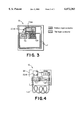
- FIG. 3 is a first embodiment of a packaging configuration for the tag of FIGS. 1 and 2;
- FIG. 4 is a second embodiment of a packaging configuration for the tag of FIGS. 1 and 2.
- FIGS. 1 and 2 are equivalent circuit diagrams of one preferred embodiment of the present invention.
- FIGS. 1 and 2 are representations of the same circuit, but in different states.
- the circuitry of FIGS. 1 and 2 are described in detail, followed by a discussion of the theory of operation of the circuit diagrams.
- the embodiment of the invention described herein is used with radio frequency identification (RFID) tags or transponders.
- RFID radio frequency identification
- FIG. 1 is an equivalent electrical circuit diagram of an RFID reader or interrogator (hereafter, "interrogator 10") and a resonant RFID device, tag or transponder (hereafter, “transponder 12").
- the interrogator 10 includes a voltage source 14 electrically connected to a transmitter coil or antenna 16 for generating an electromagnetic field.
- the antenna 16 is primarily defined by an inductance L 0 , but also has an equivalent series resistance R 0 and capacitance C 0 , which together define a series RLC circuit. These components define a current loop labeled as Loop 0 and having a current flow I 0 .
- Interrogators which communicate with a resonant tag or transponder by inductive coupling are well known in the art. For instance, interrogators are described in U.S. Pat. Nos. 3,752,960, 3,816,708 and 4,580,041, all issued to Walton, all of which are incorporated by reference in their entirety herein. Accordingly, the interrogator 10 is not shown or described in detail. Suffice it to say that the interrogator 10 establishes an electromagnetic field at or near the resonant frequency of the transponder 12.
- the interrogator 10 may be physically implemented as a pair of smart pedestals (not shown), as a hand-held RFID scanner (not shown) or in some other manner.
- the interrogation signal generated by the interrogator 10 is preferably a generally continuous signal, as opposed to a periodic or pulsed signal.
- the interrogation zone is the area within the electromagnetic field in which a voltage is induced in the intelligent transponder 12 sufficient to power the transponder 12.
- the size of the interrogation zone is defined, at least, in part, by the strength of the electromagnetic field.
- the interrogator 10 can generally detect transmissions from a plurality of transponders 12 (and thus their associated articles) located within the interrogation zone.
- U.S. Pat. No. 5,430,441 discloses a transponding tag which transmits a digitally encoded signal in response to an interrogation signal.
- the tag in Bickley et al. comprises a rigid substrate constructed from a plurality of dielectric layers and conductive layers and includes an integrated circuit embedded entirely within a hole in the substrate and tab bonded to conductive foil traces.
- the physical structure of the transponder 12 is described below with respect to FIGS. 3 and 4.
- the transponder 12 of the present invention comprises an antenna circuit 20 electrically connected to an integrated circuit (IC) 18.
- the antenna circuit 20 comprises a resonant circuit which resonates at a predetermined radio frequency (RF) corresponding to a radio frequency of the interrogator 10, as discussed in more detail hereinafter.
- RF radio frequency
- the antenna circuit 20 may comprise one or more inductive elements electrically connected to one or more capacitive elements.
- the antenna circuit 20 is formed by the combination of a single inductive element, inductor, or coil 22 (L T ) electrically connected with a capacitive element or primary resonant capacitor 24 (C T ) in a series current loop, labeled as Loop 1.
- the inductor 22 is actually comprised of two coils wired in series, as explicitly shown in FIG. 2.
- the inductor 22 and the resonant capacitor 24 (C T ) are connected in parallel with the IC 18.
- the operational frequency of the antenna circuit 20 depends upon the values of the inductor 22 and the resonant capacitor 24. The size of the inductor 22 and the value of the capacitor 24 are determined based upon the desired resonant frequency of the antenna circuit 20.
- the transponder 12 is constructed to operate at 13.56 MHz. Although it is preferred that the transponder 12 resonates at about 13.56 MHz, the transponder 12 could be constructed to resonate at other frequencies and the precise resonant frequency of the transponder 12 is not meant to be a limitation of the present invention. Thus, it will be apparent to those of ordinary skill in the art that the antenna circuit 20 may operate at radio frequencies other than 13.56 MHz, and indeed at other frequencies, such as microwave frequencies.
- a resistor 26 (R T ) is shown connected in series with the inductor 22 which represents an equivalent series resistance of the inductor 22 due to power losses.
- the antenna circuit 20 comprises a single inductive element, namely inductor 22, and a single capacitor 24, multiple inductor and capacitor elements could also be employed.
- multiple element resonant circuits are known in the electronic security and surveillance art, such as described in U.S. Pat. No. 5,103,210 (Rode et al.) entitled “Activatable/Deactivatable Security Tag for Use with an Electronic Security System", which is incorporated herein by reference.
- a preferred antenna is described, it will be apparent to those of ordinary skill in the art from this disclosure that any means for coupling energy to/from the IC 18 may be used.
- the transponder 20 also includes a second current loop path, Loop 2.
- Loop 2 includes a secondary capacitor 28 (C SW ) in series with a switch 30 (S 1 ).
- a resistor 32 (R SW ) is shown connected in series with the capacitor 28 and the switch 30.
- the resistor 32 represents an equivalent series resistance of these components due to power losses.
- the inductor 22 is actually comprised of two coils wired in series, as explicitly shown in FIG. 2.
- Loop 2 includes the secondary capacitor 28 (C SW ), one of the two coils of the inductor 22 and its equivalent resistance (shown in more detail in FIG. 2), resistor 32 (R SW ), and switch 30 (S 1 ).
- the switch 30 (S 1 ) is open or OFF, and Loop 2 does not affect the operation of the resonant circuit defined by the inductor 22 (L T ) and the capacitor 24 (C T ).
- FIG. 2 shows the equivalent circuit in a state wherein the switch 30 (S 1 ) is closed or ON.
- FIG. 2 also shows the inductor 22 in more detail which is comprised of two inductors 22 1 (L 1T ) and 22 2 (L 2T ), wired in series.
- Inductor 22 1 (L 1T ) is the primary coil and inductor 22 2 (L 2T ) is the secondary coil.
- the secondary capacitor 28 (C SW ) is in series with the switch 30 (S 1 ) that is connected to the connection between the two inductors 22 1 (L 1T ) and 22 2 (L 2T ).
- the inductors 22 1 (L 1T ) and 22 2 (L 2T ) are coupled to one another via a mutual inductance M 12 .
- the series combination of the two inductor coils is in parallel with the primary resonating capacitor 24 (C T ).
- the resistor 26 of FIG. 1 is represented in FIG. 2 by equivalent resistors 26 1 and 26 2 corresponding to the respective inductors 22 1 and 22 2 .
- Loop 2 is more clearly defined in FIG. 2 and includes the capacitor 28 (C SW ), inductor 22 2 (L 2T ), resistor 26 2 (R 2T ), resistor 32 (R SW ), and switch 30 (S 1 ).
- a parallel resonant circuit 34 is formed with the capacitor 28 (C SW ) and the inductor 22 2 (L 2T ).
- the impedance of the parallel resonant circuit 34 is ideally infinite.
- resistive losses in the components and in the switch 30 (S 1 ) limit the maximum impedance that can be realized, and are modeled by the resistor 26 2 (R 2T ) and the resistor 32 (R SW ).
- the transponder 12 When the resonant frequency of a transponder is moved far away from its primary resonant frequency or fundamental frequency, here 13.56 MHz, the transponder 12 will have little or no loading effect on the interrogator 10, and will have little or no effect on a field resonating at the primary resonant frequency. More importantly, the transponder 12 will have little or no loading effect on other transponders in near proximity. The transponder would thus be decoupled from its environment or "cloaked.”
- a resonant circuit may be selectively shorted and opened depending upon how it is connected.
- a series resonant circuit forms a short at its resonant frequency, whereas a parallel resonant circuit forms an open circuit at its resonant frequency.
- the present invention uses a high impedance (ideally, infinite impedance) second resonant circuit comprising the capacitor 28 (C SW ) and the inductor 22 2 (L 2T ) to form an open circuit at the transponder's resonant frequency.
- the switch 30 (S 1 ) must be in the closed or ON position (FIG. 2) to form the open circuit.
- the open circuit functions to disconnect L 1T from C T , thereby preventing the transponder 12 from resonating at the primary resonant frequency.
- the switch S 1 When the switch S 1 is in the open or OFF position (FIG. 1), the second resonant circuit has no effect, and the transponder 12 resonates at the primary resonant frequency in the normal manner.
- the switch S 1 may perform two different functions. First, the switch S 1 may be placed and maintained in the open position to allow the transponder 12 to be activatable upon receipt of the primary resonant frequency signal, or it may be placed and maintained in the closed position to permanently shut down the transponder 12 (i.e., put the transponder 12 to sleep) and thereby prevent it from interfering with the environment.
- the switch S 1 may be selectively moved between the open position and the closed position, in accordance with a stored data pattern (e.g., identification data stored in the transponder's IC chip 18) to tune and detune the antenna circuit comprising L T and C T , such that the stored data is transmitted to the reader.
- a stored data pattern e.g., identification data stored in the transponder's IC chip 18
- the present invention may use the switch S 1 in lieu of a modulation capacitor to tune and detune the antenna circuit and transmit data to a reader.
- the switch closed position which is the transponder state during modulation and during cloaking, the transponder 12 is essentially removed from the environment.
- the switch S 1 serves two purposes when it is in the closed position, as follows:
- the transponder 12 is thus particularly suitable for environments, such as retail stores, where many tagged articles are physically close to one another, and it is desirable to read the identity codes of all of these articles. After the code of an article is read, the closed switch position removes the article's transponder from the environment magnetically (as opposed to physically) so that it will not detune, shadow or otherwise interfere with the reading of transponders in neighboring articles.
- the position of the switch S 1 functions to either (1) form the open circuit with the second parallel resonant circuit, thereby preventing the transponder 12 from resonating at its resonant frequency and decoupling the transponder 12 from its environment, or (2) prevent the second parallel resonant circuit from having any influence on the transponder 12, thereby allowing the transponder 12 to operate in the normal manner where it is allowed to resonate at its primary resonant frequency.
- the circuit design should minimize M 12 (i.e., the mutual inductance/coupling coefficient between L 1T and L 2T ), as well as M 02 (i.e., the mutual inductance/coupling coefficient between L 0 and L 2T ) M 12 may be minimized by a careful layout of the geometrical orientation of the two inductor coils L 1T and L 2T . This may be accomplished by using conventional methods for minimizing coupling between two coil antennas through optimum overlap of the coils. Since such methods are conventional, no further description is provided herein.
- the parallel resonant frequency formed by the capacitor 28 (C SW ) and the inductor 22 2 (L 2T ) is given by: ##EQU2##
- the frequency of the parallel resonant circuit 34, f PAR is chosen to be equal to f 0 , thereby providing the greatest achievable impedance difference and a coupling coefficient which approaches zero.
- the values for L 2T , M 02 and M 12 are given, since the coil geometry is given and a measurement of the net L 2T may be obtained. Thus, the equation may be solved for C SW .
- the capacitance value (C SW ) is determined for the worst case conditions which occurs when the transponder 12 is at a maximum detectable distance from the antenna. At this distance, mutual coupling between the antenna and the transponder 12 is at a minimum, and the total inductance is dominated by the inductance of the transponder 12. That is, the mutual inductance of the transponder 12 and antenna is smaller than the inductance of the transponder coil.
- the IC 18, provided for storing data is a passive device which is powered by the voltage induced in the antenna circuit 20 by the interrogator 10. That is, when the transponder 12 is close enough to the interrogator 10 so as to be within the electromagnetic field, the voltage induced on the inductor 22 provides power to the IC 18 at an antenna input (not shown) of the IC 18.
- the IC 18 internally rectifies the induced AC voltage at the antenna input to provide an internal DC voltage source. When the internal DC voltage reaches a level that assures proper operation of the IC 18, the IC 18 functions to output a digital value stored in the programmable memory at a modulation output (not shown) of the IC 18.
- one method of transmitting the data stored in the IC 18 to a reader is through the use of a modulation capacitor connected to the modulation output of the IC 18 and to the antenna circuit 20.
- the data output pulses at the modulation output switch a modulation capacitor into and out of the antenna circuit 20 by making and breaking ground connections to change the overall capacitance of the circuit 20 in accordance with the stored data, which in turn changes the resonant frequency of the circuit 20, detuning it from the first predetermined resonant frequency to a predetermined higher or lower frequency.
- data pulses of the transponder 12 are created by the tuning and detuning of the resonant antenna circuit 20, such that instead of the antenna circuit 20 returning a simple single frequency response signal, it returns a signal containing a packet of preprogrammed information.
- the present invention may use the switch S 1 in lieu of a modulation capacitor to tune and detune the antenna circuit and transmit data to a reader.
- the packet of information (data pulses) is received and processed by receiving circuitry (not shown) usually associated with the interrogator 10. That is, the receiving circuitry senses the changes in the consumption of energy within the electromagnetic field of the interrogator 10 to determine the digital data value output from the IC 18. If necessary, the data is decoded by the interrogator 10 or circuitry associated therewith to provide identification or other information about an article or person with which the transponder 12 is associated. It is presently preferred to use a passive IC 18 which is powered by the voltage induced in the antenna circuit 20. However, other means for powering the IC 18, such as a battery, are within the scope of the present invention.
- the IC 18 may also include a power return or ground output (not shown) and one or more additional inputs (not shown) which are used for programming the IC 18 (i.e. storing or altering the digital value stored therein) in a conventional manner.
- the IC 18 comprises 128 bits of nonvolatile memory.
- the IC 18 could have either a greater or smaller storage capacity.
- FIG. 1 SW-OFF Case
- FIG. 2 SW-ON Case
- Constants provided for the interrogator 10 (antenna) and the transponder 12 (tag) in an experimental simulation of the present invention are as follows: ##EQU6##
- FIG. 3 is a first embodiment of a packaging configuration for the transponder 12 implemented as a paper tag having all inductors, capacitors, and the IC 18 thereon.
- the packaging configuration shows the placement of the four key components, inductor 22 1 (L 1T ), inductor 22 2 (L 2T ), primary resonating capacitor 24 (C T ) and secondary capacitor (C SW ).
- the bottom layer conductor below L 2T may help to decouple L 2T with another transponder coil and the antenna.
- the switch 30 (S 1 ) preferably resides in the IC 18, but alternatively may be realized with a discrete transistor.
- the capacitors C T and C SW are fabricated with aluminum foil plates that sandwich a polyethylene dielectric. This fabrication process is conventional and thus is not described in more detail herein. Alternative embodiments use discrete chip capacitors using other types of dielectrics (e.g., ceramic, tantalum) and/or other types of form factors, namely, surface mount, leaded or thick film printed capacitors. One or both of the capacitors may reside inside an IC chip. At least one of the capacitors, such as C T , may be a "distributed" capacitance between the coils of L 1T and L 2T . A distributed capacitance is formed from lengths of inductors, as opposed to using a discrete component, as is well-known in the art.
- both of the inductor coils L 1T and L 2T are etched onto a laminated aluminum structure.
- At least one of the inductor coils is etched or stamped onto a laminated aluminum structure. These inductor coils may reside in the same or different sides of the laminated structure.
- the other inductor coil may be stamped or may be fabricated with a discrete inductor coil.
- the discrete inductor coil may have a surface mountable, or leaded (through hole) form factor.
- One alternative embodiment uses one etched or stamped aluminum coil and one discrete coil that may be in a surface mount package. This embodiment offers flexibility in the geometric orientation of the coils, which is helpful in minimizing coupling between the two coils.
- Other alternative embodiments may use permutations of stamped coils with discrete and/or etched coils. Alternatively, these coils may be embodied with loops of copper or aluminum wire. This technique is commonly used for reusable, hard tags.
- the inductor coils may also be fabricated using ferromagnetic materials.
- Aluminum is the preferred material to be used in the construction of the inductor coils and/or capacitor plates, primarily for cost purposes. However, if cost is not a primary concern, other metallic materials with high electrical conductivity may be used for the inductor coils and/or capacitor plates. Such materials include copper, tin, lead, nickel, gold, silver, tungsten, titanium, molybdenum, platinum, and alloys of such metals.
- FIG. 4 is a second embodiment of a packaging configuration for the transponder 12.
- the primary coil L 1T is implemented as a single layer paper tag coil.
- the secondary coil L 2T and the two capacitors C T and C SW are put on a printed circuit (PC) board 36.
- the secondary coil L 2T has a high Q.
- the switch 30 (S 1 ) (not shown) is also put on the PC board 36.
Abstract
Description
Claims (5)
Priority Applications (14)
| Application Number | Priority Date | Filing Date | Title |
|---|---|---|---|
| US09/185,775 US6072383A (en) | 1998-11-04 | 1998-11-04 | RFID tag having parallel resonant circuit for magnetically decoupling tag from its environment |
| EP99954895A EP1127469B1 (en) | 1998-11-04 | 1999-10-14 | Rfid tag having parallel resonant circuit for magnetically decoupling tag from its environment |
| PCT/US1999/023886 WO2000027137A1 (en) | 1998-11-04 | 1999-10-14 | Rfid tag having parallel resonant circuit for magnetically decoupling tag from its environment |
| JP2000580397A JP4261065B2 (en) | 1998-11-04 | 1999-10-14 | RFID tag with parallel resonant circuit to magnetically isolate the tag from the environment |
| AU11129/00A AU751418B2 (en) | 1998-11-04 | 1999-10-14 | Rfid tag having parallel resonant circuit for magnetically decoupling tag from its environment |
| CA002349409A CA2349409C (en) | 1998-11-04 | 1999-10-14 | Rfid tag having parallel resonant circuit for magnetically decoupling tag from its environment |
| CNB998126160A CN1146250C (en) | 1998-11-04 | 1999-10-14 | Frid tag having parallet resonant circuit for magnetically decoupling tag from its environment |
| AT99954895T ATE246382T1 (en) | 1998-11-04 | 1999-10-14 | HIGH FREQUENCY MARKER WITH PARALLEL RESOLUTION CIRCUIT FOR MAGNETICALLY DECOUPLING THE MARKER FROM ITS SURROUNDINGS |
| DE69910061T DE69910061T2 (en) | 1998-11-04 | 1999-10-14 | HIGH-FREQUENCY BRAND WITH PARALLEL VIBRATION CIRCUIT FOR MAGNETICALLY UNCOUPLING THE BRAND FROM ITS SURROUNDINGS |
| DK99954895T DK1127469T3 (en) | 1998-11-04 | 1999-10-14 | RFID identification tag with parallel resonant circuit for magnetic decoupling of the identification tag from its surroundings |
| KR1020017005527A KR100632716B1 (en) | 1998-11-04 | 1999-10-14 | Rfid tag having parallel resonant circuit for magnetically decoupling tag from its environment |
| ES99954895T ES2205899T3 (en) | 1998-11-04 | 1999-10-14 | RADIO FREQUENCY IDENTIFICATION LABEL WITH A PARALLEL RESONANT CIRCUIT TO MAGNETICALLY UNPLUG THE LABEL OF YOUR ENVIRONMENT. |
| ARP990105378A AR020961A1 (en) | 1998-11-04 | 1999-10-25 | TRANSPONDER |
| TW088119138A TW460852B (en) | 1998-11-04 | 1999-11-03 | RFID tag having parallel resonant circuit for magnetically decoupling TAG from its environment |
Applications Claiming Priority (1)
| Application Number | Priority Date | Filing Date | Title |
|---|---|---|---|
| US09/185,775 US6072383A (en) | 1998-11-04 | 1998-11-04 | RFID tag having parallel resonant circuit for magnetically decoupling tag from its environment |
Publications (1)
| Publication Number | Publication Date |
|---|---|
| US6072383A true US6072383A (en) | 2000-06-06 |
Family
ID=22682407
Family Applications (1)
| Application Number | Title | Priority Date | Filing Date |
|---|---|---|---|
| US09/185,775 Expired - Lifetime US6072383A (en) | 1998-11-04 | 1998-11-04 | RFID tag having parallel resonant circuit for magnetically decoupling tag from its environment |
Country Status (14)
| Country | Link |
|---|---|
| US (1) | US6072383A (en) |
| EP (1) | EP1127469B1 (en) |
| JP (1) | JP4261065B2 (en) |
| KR (1) | KR100632716B1 (en) |
| CN (1) | CN1146250C (en) |
| AR (1) | AR020961A1 (en) |
| AT (1) | ATE246382T1 (en) |
| AU (1) | AU751418B2 (en) |
| CA (1) | CA2349409C (en) |
| DE (1) | DE69910061T2 (en) |
| DK (1) | DK1127469T3 (en) |
| ES (1) | ES2205899T3 (en) |
| TW (1) | TW460852B (en) |
| WO (1) | WO2000027137A1 (en) |
Cited By (84)
| Publication number | Priority date | Publication date | Assignee | Title |
|---|---|---|---|---|
| US6275158B1 (en) * | 1998-12-22 | 2001-08-14 | U.S. Philips Corporation | Device arranged for contactless communication and provided with a data carrier with fully enclosed connection means for electrically connecting a chip and a passive component |
| US20010015697A1 (en) * | 2000-01-31 | 2001-08-23 | Luc Wuidart | Adaptation of the transmission power of an electromagnetic transponder reader |
| US20020003498A1 (en) * | 2000-05-17 | 2002-01-10 | Luc Wuidart | Electromagnetic field generation antenna for a transponder |
| US20020017991A1 (en) * | 2000-05-17 | 2002-02-14 | Luc Wuidart | Electromagnetic field generation device for a transponder |
| US20020021207A1 (en) * | 2000-05-12 | 2002-02-21 | Luc Wuidart | Evaluation of the number of electromagnetic transponders in the field of a reader |
| US6356198B1 (en) * | 1998-12-21 | 2002-03-12 | Stmicroelectronics S.A. | Capacitive modulation in an electromagnetic transponder |
| WO2002013135A3 (en) * | 2000-08-04 | 2002-04-25 | Hei Inc | Structures and assembly methods for radio-frequency-identification modules |
| US6393045B1 (en) * | 1997-09-26 | 2002-05-21 | Wherenet Corp. | Spread spectrum baseband modulation of magnetic fields for communications and proximity sensing |
| US20020097143A1 (en) * | 2001-01-23 | 2002-07-25 | Dave Dalglish | Selective cloaking circuit for use in a radiofrequency identification and method of cloaking RFID tags |
| US6465903B1 (en) | 1998-06-22 | 2002-10-15 | Stmicroelectronics S.A. | Transmission of an operating order via an A.C. supply line |
| US20020152604A1 (en) * | 2001-04-23 | 2002-10-24 | Debraal John Charles | Method and system for forming electrically conductive pathways |
| US6473028B1 (en) | 1999-04-07 | 2002-10-29 | Stmicroelectronics S.A. | Detection of the distance between an electromagnetic transponder and a terminal |
| US6476709B1 (en) | 1998-06-22 | 2002-11-05 | Stmicroelectronics S.A. | Transmission of digital data over an A.C. supply line |
| US6547149B1 (en) * | 1999-04-07 | 2003-04-15 | Stmicroelectronics S.A. | Electromagnetic transponder operating in very close coupling |
| US20030164742A1 (en) * | 2000-08-09 | 2003-09-04 | Luc Wuidart | Detection of an electric signature of an electromagnetic transponder |
| US6617959B1 (en) * | 2000-09-29 | 2003-09-09 | Mei-Chin Kuo | Non-contact chip lock and battery-free key thereof |
| US20030169169A1 (en) * | 2000-08-17 | 2003-09-11 | Luc Wuidart | Antenna generating an electromagnetic field for transponder |
| US6650226B1 (en) | 1999-04-07 | 2003-11-18 | Stmicroelectronics S.A. | Detection, by an electromagnetic transponder reader, of the distance separating it from a transponder |
| US6650229B1 (en) | 1999-04-07 | 2003-11-18 | Stmicroelectronics S.A. | Electromagnetic transponder read terminal operating in very close coupling |
| US6703921B1 (en) | 1999-04-07 | 2004-03-09 | Stmicroelectronics S.A. | Operation in very close coupling of an electromagnetic transponder system |
| US20040069856A1 (en) * | 2000-10-04 | 2004-04-15 | Philippe Held | Transponder unit and transport unit and card |
| US6768977B1 (en) * | 1999-11-30 | 2004-07-27 | Texas Instruments Incorporated | Method and circuit for modeling a voice coil actuator of a mass data storage device |
| US20040149736A1 (en) * | 2003-01-30 | 2004-08-05 | Thermal Solutions, Inc. | RFID-controlled smart induction range and method of cooking and heating |
| US6779246B2 (en) | 2001-04-23 | 2004-08-24 | Appleton Papers Inc. | Method and system for forming RF reflective pathways |
| US6784785B1 (en) | 1999-04-07 | 2004-08-31 | Stmicroelectronics S.A. | Duplex transmission in an electromagnetic transponder system |
| US20040217171A1 (en) * | 2003-04-29 | 2004-11-04 | Devos John A. | Electronic identification label and interrogator for use therewith |
| US20040233042A1 (en) * | 2003-05-19 | 2004-11-25 | Checkpoint Systems, Inc | EAS/RFID identification hard tags |
| US20040263319A1 (en) * | 2003-06-30 | 2004-12-30 | Nokia Corporation | System and method for supporting multiple reader-tag configurations using multi-mode radio frequency tag |
| US20050057341A1 (en) * | 2003-09-17 | 2005-03-17 | Roesner Bruce B. | Deep sleep in an RFID tag |
| US6879809B1 (en) * | 1998-04-16 | 2005-04-12 | Motorola, Inc. | Wireless electrostatic charging and communicating system |
| US20050184872A1 (en) * | 2004-02-23 | 2005-08-25 | Clare Thomas J. | Identification marking and method for applying the identification marking to an item |
| US20050183817A1 (en) * | 2004-02-23 | 2005-08-25 | Eric Eckstein | Security tag system for fabricating a tag including an integrated surface processing system |
| US20050183264A1 (en) * | 2004-02-23 | 2005-08-25 | Eric Eckstein | Method for aligning capacitor plates in a security tag and a capacitor formed thereby |
| US20050184873A1 (en) * | 2004-02-23 | 2005-08-25 | Eric Eckstein | Tag having patterned circuit elements and a process for making same |
| US20050187837A1 (en) * | 2004-02-23 | 2005-08-25 | Eric Eckstein | Method and system for determining billing information in a tag fabrication process |
| WO2005093455A1 (en) * | 2004-03-29 | 2005-10-06 | Magellan Technology Pty Ltd. | An article supply chain and/or authentication, monitoring, tracking and identification system, method and device |
| US20050247696A1 (en) * | 2004-04-22 | 2005-11-10 | Clothier Brian L | Boil detection method and computer program |
| WO2005121832A1 (en) * | 2004-06-09 | 2005-12-22 | Magellan Technology Pty Ltd | Method, system and apparatus for document management |
| US7005967B2 (en) | 2000-05-12 | 2006-02-28 | Stmicroelectronics S.A. | Validation of the presence of an electromagnetic transponder in the field of an amplitude demodulation reader |
| US7006014B1 (en) | 2000-10-17 | 2006-02-28 | Henty David L | Computer system with passive wireless keyboard |
| US20060092013A1 (en) * | 2004-10-07 | 2006-05-04 | West Pharmaceutical Services, Inc. | Closure for a container |
| US7049936B2 (en) | 2000-05-12 | 2006-05-23 | Stmicroelectronics S.A. | Validation of the presence of an electromagnetic transponder in the field of a reader |
| US7049935B1 (en) | 1999-07-20 | 2006-05-23 | Stmicroelectronics S.A. | Sizing of an electromagnetic transponder system for a dedicated distant coupling operation |
| US20060111043A1 (en) * | 2000-05-12 | 2006-05-25 | Stmicroelectronics S.A. | Validation of the presence of an electromagnetic transponder in the field of a phase demodulation reader |
| US7058357B1 (en) | 1999-07-20 | 2006-06-06 | Stmicroelectronics S.A. | Sizing of an electromagnetic transponder system for an operation in extreme proximity |
| US20060226955A1 (en) * | 2002-08-22 | 2006-10-12 | Murdoch Graham A M | Identification device and identification system |
| US7152804B1 (en) * | 2004-03-15 | 2006-12-26 | Kovlo, Inc. | MOS electronic article surveillance, RF and/or RF identification tag/device, and methods for making and using the same |
| US20070030119A1 (en) * | 2005-07-08 | 2007-02-08 | Mitsubishi Denki Kabushiki Kaisha | Communication apparatus for vehicle |
| US20070096852A1 (en) * | 2005-06-25 | 2007-05-03 | Qinetiq Limited | Electromagnetic radiation decoupler |
| US20070129602A1 (en) * | 2005-11-22 | 2007-06-07 | Given Imaging Ltd. | Device, method and system for activating an in-vivo imaging device |
| US20070171129A1 (en) * | 2006-01-24 | 2007-07-26 | Avery Dennison Corporation | Radio frequency (RF) antenna containing element and methods of making the same |
| US20070262868A1 (en) * | 2006-05-12 | 2007-11-15 | Westrick Michael D | Rf passive repeater for a metal container |
| US20070262867A1 (en) * | 2006-05-12 | 2007-11-15 | Westrick Michael D | Rfid coupler for metallic implements |
| US20070290941A1 (en) * | 2006-06-16 | 2007-12-20 | Qinetiq Limited | Electromagnetic Enhancement and Decoupling |
| US20070290856A1 (en) * | 2006-06-19 | 2007-12-20 | Tagsys Sas | RFID tag detuning |
| US7324061B1 (en) * | 2003-05-20 | 2008-01-29 | Alien Technology Corporation | Double inductor loop tag antenna |
| US20080211621A1 (en) * | 2005-05-23 | 2008-09-04 | Nxp B.V. | Electronic Communication System, in Particular Authentication Control System, as Well as Corresponding Method |
| US20080266101A1 (en) * | 2007-04-27 | 2008-10-30 | Sensormatic Electronics Corporation | Security tag sensor and seccurity meethod for capital assets |
| US20080308641A1 (en) * | 2007-04-10 | 2008-12-18 | Advanced Microelectronic And Automation Technology Ltd. | Smart card with switchable matching antenna |
| US20090015075A1 (en) * | 2007-07-09 | 2009-01-15 | Nigel Power, Llc | Wireless Energy Transfer Using Coupled Antennas |
| US20090096613A1 (en) * | 2007-10-12 | 2009-04-16 | Westrick Michael D | Small gamma shielded shorted patch rfid tag |
| US20090102292A1 (en) * | 2007-09-19 | 2009-04-23 | Nigel Power, Llc | Biological Effects of Magnetic Power Transfer |
| US20090247079A1 (en) * | 2008-03-31 | 2009-10-01 | Stmicroelectronics (Rousset) Sas | Terminal of radio-frequency transmission/reception by inductive coupling |
| US20100045025A1 (en) * | 2008-08-20 | 2010-02-25 | Omni-Id Limited | One and Two-Part Printable EM Tags |
| US7704346B2 (en) | 2004-02-23 | 2010-04-27 | Checkpoint Systems, Inc. | Method of fabricating a security tag in an integrated surface processing system |
| US20100147832A1 (en) * | 2008-12-16 | 2010-06-17 | Barker Iii Charles R | Induction cookware identifying |
| US20100156563A1 (en) * | 2006-01-19 | 2010-06-24 | Murata Manufacturing Co., Ltd. | Wireless ic device and component for wireless ic device |
| US20100230497A1 (en) * | 2006-12-20 | 2010-09-16 | Omni-Id Limited | Radiation Enhancement and Decoupling |
| US20110037541A1 (en) * | 2006-12-14 | 2011-02-17 | Omni-Id Limited | Switchable Radiation Enhancement and Decoupling |
| US20110084814A1 (en) * | 2009-10-08 | 2011-04-14 | Checkpoint Systems, Inc. | Security tag utilizing rfid reflectivity mode power rationing |
| US20110115607A1 (en) * | 2009-11-19 | 2011-05-19 | Panasonic Corporation | Transmitting / receiving antenna and transmitter / receiver device using the same |
| US20110193422A1 (en) * | 2010-02-05 | 2011-08-11 | Honeywell International Inc. | Secure non-contact switch |
| US20110193663A1 (en) * | 2010-02-05 | 2011-08-11 | Honeywell International Inc. | Secure non-contact switch |
| US20140287691A1 (en) * | 2013-03-20 | 2014-09-25 | Cubic Corporation | Signal enhancement for load modulation |
| US8931166B2 (en) | 2011-05-19 | 2015-01-13 | Tecnomar Oy | Manufacturing method of electrical bridges suitable for reel to reel mass manufacturing |
| US9094057B2 (en) | 2010-08-25 | 2015-07-28 | Qualcomm Incorporated | Parasitic circuit for device protection |
| US9231290B2 (en) | 2010-06-14 | 2016-01-05 | Avery Dennison Corporation | Method for making short run radio frequency identification tags and labels |
| US20160127116A1 (en) * | 2011-10-26 | 2016-05-05 | Texas Instruments Deutschland Gmbh | Electronic device, method and system for half duplex data transmission |
| US9355349B2 (en) | 2013-03-07 | 2016-05-31 | Applied Wireless Identifications Group, Inc. | Long range RFID tag |
| US20160351034A1 (en) * | 2015-05-27 | 2016-12-01 | Tyco Fire & Security Gmbh | Self-detachable rfid tags |
| US20180038925A1 (en) * | 2016-08-04 | 2018-02-08 | Bruker Biospin Gmbh | High-frequency interface circuit, high-frequency system and magnet resonance apparatus with a high-frequency interface circuit |
| EP3333776A1 (en) * | 2016-12-07 | 2018-06-13 | Porta Saber Lda | Activating rfid transponder with light |
| US11527138B2 (en) | 2018-05-17 | 2022-12-13 | Checkpoint Systems, Inc. | Dual hard tag |
| US20230102380A1 (en) * | 2020-02-14 | 2023-03-30 | Rapitag Gmbh | Product anti-theft system and method for operating a product anti-theft system |
Families Citing this family (25)
| Publication number | Priority date | Publication date | Assignee | Title |
|---|---|---|---|---|
| WO2002041650A1 (en) | 2000-11-16 | 2002-05-23 | Checkpoint Systems, Inc. | Anticollision protocol with fast read request and additional schemes for reading multiple transponders in an rfid system |
| US6696951B2 (en) * | 2001-06-13 | 2004-02-24 | 3M Innovative Properties Company | Field creation in a magnetic electronic article surveillance system |
| KR20030085782A (en) * | 2002-05-02 | 2003-11-07 | 한병성 | An individual Recognition System Using Inductive Transmission Method |
| JP4536552B2 (en) * | 2005-02-28 | 2010-09-01 | ケイ・アール・ディコーポレーション株式会社 | IC tag |
| DE102006044881A1 (en) * | 2005-09-28 | 2007-04-12 | Giesecke & Devrient Gmbh | Portable data carrier and method for operating a portable data carrier |
| US7639095B2 (en) * | 2005-09-28 | 2009-12-29 | Tyco Electronics Belgium Ec N.V. | Circuit and method for contact-less transmission |
| KR100968347B1 (en) * | 2006-04-14 | 2010-07-08 | 가부시키가이샤 무라타 세이사쿠쇼 | Antenna |
| US7821402B2 (en) | 2006-05-05 | 2010-10-26 | Quality Electrodynamics | IC tags/RFID tags for magnetic resonance imaging applications |
| JP4239205B2 (en) | 2006-06-08 | 2009-03-18 | ソニー・エリクソン・モバイルコミュニケーションズ株式会社 | Mobile communication terminal device |
| JP2009015683A (en) * | 2007-07-06 | 2009-01-22 | Hst Kk | Detector |
| CN101090175B (en) * | 2007-07-18 | 2013-07-10 | 北京邮电大学 | Superhigh frequency RFID universal label antenna of coupled capacitor and inductance |
| KR101006489B1 (en) * | 2008-04-11 | 2011-01-07 | 신현명 | The manufacturing method for dyeing drug container |
| US8878393B2 (en) | 2008-05-13 | 2014-11-04 | Qualcomm Incorporated | Wireless power transfer for vehicles |
| US8965461B2 (en) | 2008-05-13 | 2015-02-24 | Qualcomm Incorporated | Reverse link signaling via receive antenna impedance modulation |
| US9312924B2 (en) | 2009-02-10 | 2016-04-12 | Qualcomm Incorporated | Systems and methods relating to multi-dimensional wireless charging |
| US8854224B2 (en) | 2009-02-10 | 2014-10-07 | Qualcomm Incorporated | Conveying device information relating to wireless charging |
| US20100201312A1 (en) | 2009-02-10 | 2010-08-12 | Qualcomm Incorporated | Wireless power transfer for portable enclosures |
| EP2529366B1 (en) | 2010-01-29 | 2016-11-09 | Avery Dennison Corporation | Smart sign box using electronic interactions |
| US10977965B2 (en) | 2010-01-29 | 2021-04-13 | Avery Dennison Retail Information Services, Llc | Smart sign box using electronic interactions |
| CN104025556B (en) | 2011-09-01 | 2018-08-10 | 艾利丹尼森公司 | Equipment, system and method for consumer's tracking |
| US8630908B2 (en) | 2011-11-02 | 2014-01-14 | Avery Dennison Corporation | Distributed point of sale, electronic article surveillance, and product information system, apparatus and method |
| US9734365B2 (en) | 2012-09-10 | 2017-08-15 | Avery Dennison Retail Information Services, Llc | Method for preventing unauthorized diversion of NFC tags |
| US10540527B2 (en) | 2012-10-18 | 2020-01-21 | Avery Dennison Retail Information Services Llc | Method, system and apparatus for NFC security |
| EP2795950B1 (en) | 2012-11-19 | 2018-09-05 | Avery Dennison Corporation | Nfc security system and method for disabling unauthorized tags |
| JP6428989B1 (en) * | 2017-03-29 | 2018-11-28 | 株式会社村田製作所 | ANTENNA DEVICE AND ELECTRONIC DEVICE |
Citations (31)
| Publication number | Priority date | Publication date | Assignee | Title |
|---|---|---|---|---|
| US3752960A (en) * | 1971-12-27 | 1973-08-14 | C Walton | Electronic identification & recognition system |
| US3816708A (en) * | 1973-05-25 | 1974-06-11 | Proximity Devices | Electronic recognition and identification system |
| US4481428A (en) * | 1981-05-19 | 1984-11-06 | Security Tag Systems, Inc. | Batteryless, portable, frequency divider useful as a transponder of electromagnetic radiation |
| US4580041A (en) * | 1983-12-09 | 1986-04-01 | Walton Charles A | Electronic proximity identification system with simplified low power identifier |
| US4583099A (en) * | 1983-12-27 | 1986-04-15 | Polyonics Corporation | Resonant tag circuits useful in electronic security systems |
| US4598276A (en) * | 1983-11-16 | 1986-07-01 | Minnesota Mining And Manufacturing Company | Distributed capacitance LC resonant circuit |
| US4600829A (en) * | 1984-04-02 | 1986-07-15 | Walton Charles A | Electronic proximity identification and recognition system with isolated two-way coupling |
| US4951057A (en) * | 1989-11-13 | 1990-08-21 | X-Cyte, Inc. | Inductive input/output coupling for a surface acoustic wave device |
| US5065138A (en) * | 1990-08-03 | 1991-11-12 | Security Tag Systems, Inc. | Magnetically-coupled two-resonant-circuit, frequency divider for presence-detection-system tag |
| US5072222A (en) * | 1986-08-08 | 1991-12-10 | N.V. Nederlandsche Apparatenfabriek Nedap | Electromagnetic identification and location system |
| US5084699A (en) * | 1989-05-26 | 1992-01-28 | Trovan Limited | Impedance matching coil assembly for an inductively coupled transponder |
| US5105190A (en) * | 1986-04-22 | 1992-04-14 | N.V. Nederlandsche Apparatenfabriek Nedap | Electromagnetic identification system |
| US5241298A (en) * | 1992-03-18 | 1993-08-31 | Security Tag Systems, Inc. | Electrically-and-magnetically-coupled, batteryless, portable, frequency divider |
| US5287113A (en) * | 1990-02-12 | 1994-02-15 | Texas Instruments Deutschland Gmbh | Voltage limiting batteryless transponder circuit |
| US5302901A (en) * | 1991-08-26 | 1994-04-12 | U.S. Philips Corporation | Magnetic resonance apparatus comprising decoupled receiver coils |
| US5347263A (en) * | 1993-02-05 | 1994-09-13 | Gnuco Technology Corporation | Electronic identifier apparatus and method utilizing a single chip microcontroller and an antenna coil |
| US5373303A (en) * | 1991-12-30 | 1994-12-13 | Texas Instruments Incorporated | Built-in chip transponder with antenna coil |
| US5374930A (en) * | 1993-04-14 | 1994-12-20 | Texas Instruments Deutschland Gmbh | High speed read/write AVI system |
| US5430441A (en) * | 1993-10-12 | 1995-07-04 | Motorola, Inc. | Transponding tag and method |
| US5446447A (en) * | 1994-02-16 | 1995-08-29 | Motorola, Inc. | RF tagging system including RF tags with variable frequency resonant circuits |
| US5517179A (en) * | 1995-05-18 | 1996-05-14 | Xlink Enterprises, Inc. | Signal-powered frequency-dividing transponder |
| US5550536A (en) * | 1994-08-17 | 1996-08-27 | Texas Instruments Deutschland Gmbh | Circuit frequency following technique transponder resonant |
| US5596273A (en) * | 1993-09-17 | 1997-01-21 | Seiko Instruments Inc. | Highly sensitive magnetic field detector using low-noise DC SQUID |
| US5600243A (en) * | 1993-09-07 | 1997-02-04 | Conductus, Inc. | Magnetically shielded magnetic sensor with squid and ground plane |
| US5608417A (en) * | 1994-09-30 | 1997-03-04 | Palomar Technologies Corporation | RF transponder system with parallel resonant interrogation series resonant response |
| US5610384A (en) * | 1994-09-30 | 1997-03-11 | Kabushiki Kaisha Toshiba | Magnetic coupling circuit-driving system |
| US5621323A (en) * | 1991-11-29 | 1997-04-15 | Magnetic Research, Inc. | Surface coil elements |
| US5680106A (en) * | 1995-10-27 | 1997-10-21 | International Business Machines Corporation | Multibit tag with stepwise variable frequencies |
| US5771021A (en) * | 1993-10-04 | 1998-06-23 | Amtech Corporation | Transponder employing modulated backscatter microstrip double patch antenna |
| US5793324A (en) * | 1996-01-19 | 1998-08-11 | Texas Instruments Incorporated | Transponder signal collision avoidance system |
| US5841364A (en) * | 1994-10-07 | 1998-11-24 | Texas Instruments Incorporated | Method and apparatus for transfering information from a transponder |
Family Cites Families (3)
| Publication number | Priority date | Publication date | Assignee | Title |
|---|---|---|---|---|
| SE384477B (en) * | 1974-08-16 | 1976-05-10 | Philips Svenska Ab | METHODS AND DEVICE FOR ESTABLISHING SYNCHRONIZATION IN AN INFORMATION TRANSFER SYSTEM INCLUDING A QUESTION STATION AND AN ANSWER MACHINE |
| US5701121A (en) * | 1988-04-11 | 1997-12-23 | Uniscan Ltd. | Transducer and interrogator device |
| US6208235B1 (en) * | 1997-03-24 | 2001-03-27 | Checkpoint Systems, Inc. | Apparatus for magnetically decoupling an RFID tag |
-
1998
- 1998-11-04 US US09/185,775 patent/US6072383A/en not_active Expired - Lifetime
-
1999
- 1999-10-14 DE DE69910061T patent/DE69910061T2/en not_active Expired - Lifetime
- 1999-10-14 CN CNB998126160A patent/CN1146250C/en not_active Expired - Fee Related
- 1999-10-14 AT AT99954895T patent/ATE246382T1/en not_active IP Right Cessation
- 1999-10-14 CA CA002349409A patent/CA2349409C/en not_active Expired - Fee Related
- 1999-10-14 DK DK99954895T patent/DK1127469T3/en active
- 1999-10-14 EP EP99954895A patent/EP1127469B1/en not_active Expired - Lifetime
- 1999-10-14 ES ES99954895T patent/ES2205899T3/en not_active Expired - Lifetime
- 1999-10-14 WO PCT/US1999/023886 patent/WO2000027137A1/en active IP Right Grant
- 1999-10-14 KR KR1020017005527A patent/KR100632716B1/en not_active IP Right Cessation
- 1999-10-14 JP JP2000580397A patent/JP4261065B2/en not_active Expired - Fee Related
- 1999-10-14 AU AU11129/00A patent/AU751418B2/en not_active Ceased
- 1999-10-25 AR ARP990105378A patent/AR020961A1/en not_active Application Discontinuation
- 1999-11-03 TW TW088119138A patent/TW460852B/en not_active IP Right Cessation
Patent Citations (31)
| Publication number | Priority date | Publication date | Assignee | Title |
|---|---|---|---|---|
| US3752960A (en) * | 1971-12-27 | 1973-08-14 | C Walton | Electronic identification & recognition system |
| US3816708A (en) * | 1973-05-25 | 1974-06-11 | Proximity Devices | Electronic recognition and identification system |
| US4481428A (en) * | 1981-05-19 | 1984-11-06 | Security Tag Systems, Inc. | Batteryless, portable, frequency divider useful as a transponder of electromagnetic radiation |
| US4598276A (en) * | 1983-11-16 | 1986-07-01 | Minnesota Mining And Manufacturing Company | Distributed capacitance LC resonant circuit |
| US4580041A (en) * | 1983-12-09 | 1986-04-01 | Walton Charles A | Electronic proximity identification system with simplified low power identifier |
| US4583099A (en) * | 1983-12-27 | 1986-04-15 | Polyonics Corporation | Resonant tag circuits useful in electronic security systems |
| US4600829A (en) * | 1984-04-02 | 1986-07-15 | Walton Charles A | Electronic proximity identification and recognition system with isolated two-way coupling |
| US5105190A (en) * | 1986-04-22 | 1992-04-14 | N.V. Nederlandsche Apparatenfabriek Nedap | Electromagnetic identification system |
| US5072222A (en) * | 1986-08-08 | 1991-12-10 | N.V. Nederlandsche Apparatenfabriek Nedap | Electromagnetic identification and location system |
| US5084699A (en) * | 1989-05-26 | 1992-01-28 | Trovan Limited | Impedance matching coil assembly for an inductively coupled transponder |
| US4951057A (en) * | 1989-11-13 | 1990-08-21 | X-Cyte, Inc. | Inductive input/output coupling for a surface acoustic wave device |
| US5287113A (en) * | 1990-02-12 | 1994-02-15 | Texas Instruments Deutschland Gmbh | Voltage limiting batteryless transponder circuit |
| US5065138A (en) * | 1990-08-03 | 1991-11-12 | Security Tag Systems, Inc. | Magnetically-coupled two-resonant-circuit, frequency divider for presence-detection-system tag |
| US5302901A (en) * | 1991-08-26 | 1994-04-12 | U.S. Philips Corporation | Magnetic resonance apparatus comprising decoupled receiver coils |
| US5621323A (en) * | 1991-11-29 | 1997-04-15 | Magnetic Research, Inc. | Surface coil elements |
| US5373303A (en) * | 1991-12-30 | 1994-12-13 | Texas Instruments Incorporated | Built-in chip transponder with antenna coil |
| US5241298A (en) * | 1992-03-18 | 1993-08-31 | Security Tag Systems, Inc. | Electrically-and-magnetically-coupled, batteryless, portable, frequency divider |
| US5347263A (en) * | 1993-02-05 | 1994-09-13 | Gnuco Technology Corporation | Electronic identifier apparatus and method utilizing a single chip microcontroller and an antenna coil |
| US5374930A (en) * | 1993-04-14 | 1994-12-20 | Texas Instruments Deutschland Gmbh | High speed read/write AVI system |
| US5600243A (en) * | 1993-09-07 | 1997-02-04 | Conductus, Inc. | Magnetically shielded magnetic sensor with squid and ground plane |
| US5596273A (en) * | 1993-09-17 | 1997-01-21 | Seiko Instruments Inc. | Highly sensitive magnetic field detector using low-noise DC SQUID |
| US5771021A (en) * | 1993-10-04 | 1998-06-23 | Amtech Corporation | Transponder employing modulated backscatter microstrip double patch antenna |
| US5430441A (en) * | 1993-10-12 | 1995-07-04 | Motorola, Inc. | Transponding tag and method |
| US5446447A (en) * | 1994-02-16 | 1995-08-29 | Motorola, Inc. | RF tagging system including RF tags with variable frequency resonant circuits |
| US5550536A (en) * | 1994-08-17 | 1996-08-27 | Texas Instruments Deutschland Gmbh | Circuit frequency following technique transponder resonant |
| US5608417A (en) * | 1994-09-30 | 1997-03-04 | Palomar Technologies Corporation | RF transponder system with parallel resonant interrogation series resonant response |
| US5610384A (en) * | 1994-09-30 | 1997-03-11 | Kabushiki Kaisha Toshiba | Magnetic coupling circuit-driving system |
| US5841364A (en) * | 1994-10-07 | 1998-11-24 | Texas Instruments Incorporated | Method and apparatus for transfering information from a transponder |
| US5517179A (en) * | 1995-05-18 | 1996-05-14 | Xlink Enterprises, Inc. | Signal-powered frequency-dividing transponder |
| US5680106A (en) * | 1995-10-27 | 1997-10-21 | International Business Machines Corporation | Multibit tag with stepwise variable frequencies |
| US5793324A (en) * | 1996-01-19 | 1998-08-11 | Texas Instruments Incorporated | Transponder signal collision avoidance system |
Cited By (172)
| Publication number | Priority date | Publication date | Assignee | Title |
|---|---|---|---|---|
| US6393045B1 (en) * | 1997-09-26 | 2002-05-21 | Wherenet Corp. | Spread spectrum baseband modulation of magnetic fields for communications and proximity sensing |
| US6879809B1 (en) * | 1998-04-16 | 2005-04-12 | Motorola, Inc. | Wireless electrostatic charging and communicating system |
| US6476709B1 (en) | 1998-06-22 | 2002-11-05 | Stmicroelectronics S.A. | Transmission of digital data over an A.C. supply line |
| US6465903B1 (en) | 1998-06-22 | 2002-10-15 | Stmicroelectronics S.A. | Transmission of an operating order via an A.C. supply line |
| US6356198B1 (en) * | 1998-12-21 | 2002-03-12 | Stmicroelectronics S.A. | Capacitive modulation in an electromagnetic transponder |
| US6275158B1 (en) * | 1998-12-22 | 2001-08-14 | U.S. Philips Corporation | Device arranged for contactless communication and provided with a data carrier with fully enclosed connection means for electrically connecting a chip and a passive component |
| US6784785B1 (en) | 1999-04-07 | 2004-08-31 | Stmicroelectronics S.A. | Duplex transmission in an electromagnetic transponder system |
| US6650226B1 (en) | 1999-04-07 | 2003-11-18 | Stmicroelectronics S.A. | Detection, by an electromagnetic transponder reader, of the distance separating it from a transponder |
| US6703921B1 (en) | 1999-04-07 | 2004-03-09 | Stmicroelectronics S.A. | Operation in very close coupling of an electromagnetic transponder system |
| US6473028B1 (en) | 1999-04-07 | 2002-10-29 | Stmicroelectronics S.A. | Detection of the distance between an electromagnetic transponder and a terminal |
| US6650229B1 (en) | 1999-04-07 | 2003-11-18 | Stmicroelectronics S.A. | Electromagnetic transponder read terminal operating in very close coupling |
| US6547149B1 (en) * | 1999-04-07 | 2003-04-15 | Stmicroelectronics S.A. | Electromagnetic transponder operating in very close coupling |
| US20060172702A1 (en) * | 1999-07-20 | 2006-08-03 | St Microelectronics | Sizing of an electromagnetic transponder system for an operation in extreme proximity |
| US7058357B1 (en) | 1999-07-20 | 2006-06-06 | Stmicroelectronics S.A. | Sizing of an electromagnetic transponder system for an operation in extreme proximity |
| US7049935B1 (en) | 1999-07-20 | 2006-05-23 | Stmicroelectronics S.A. | Sizing of an electromagnetic transponder system for a dedicated distant coupling operation |
| US6768977B1 (en) * | 1999-11-30 | 2004-07-27 | Texas Instruments Incorporated | Method and circuit for modeling a voice coil actuator of a mass data storage device |
| US20010015697A1 (en) * | 2000-01-31 | 2001-08-23 | Luc Wuidart | Adaptation of the transmission power of an electromagnetic transponder reader |
| US6960985B2 (en) | 2000-01-31 | 2005-11-01 | Stmicroelectronics S.A. | Adaptation of the transmission power of an electromagnetic transponder reader |
| US6879246B2 (en) | 2000-05-12 | 2005-04-12 | Stmicroelectronics S.A. | Evaluation of the number of electromagnetic transponders in the field of a reader |
| US7263330B2 (en) | 2000-05-12 | 2007-08-28 | Stmicroelectronics S.A. | Validation of the presence of an electromagnetic transponder in the field of a phase demodulation reader |
| US20060111043A1 (en) * | 2000-05-12 | 2006-05-25 | Stmicroelectronics S.A. | Validation of the presence of an electromagnetic transponder in the field of a phase demodulation reader |
| US7005967B2 (en) | 2000-05-12 | 2006-02-28 | Stmicroelectronics S.A. | Validation of the presence of an electromagnetic transponder in the field of an amplitude demodulation reader |
| US20020021207A1 (en) * | 2000-05-12 | 2002-02-21 | Luc Wuidart | Evaluation of the number of electromagnetic transponders in the field of a reader |
| US7049936B2 (en) | 2000-05-12 | 2006-05-23 | Stmicroelectronics S.A. | Validation of the presence of an electromagnetic transponder in the field of a reader |
| US7046146B2 (en) | 2000-05-17 | 2006-05-16 | Stmicroelectronics S.A. | Electromagnetic field generation device for a transponder |
| US20020003498A1 (en) * | 2000-05-17 | 2002-01-10 | Luc Wuidart | Electromagnetic field generation antenna for a transponder |
| US7023391B2 (en) * | 2000-05-17 | 2006-04-04 | Stmicroelectronics S.A. | Electromagnetic field generation antenna for a transponder |
| US20020017991A1 (en) * | 2000-05-17 | 2002-02-14 | Luc Wuidart | Electromagnetic field generation device for a transponder |
| WO2002013135A3 (en) * | 2000-08-04 | 2002-04-25 | Hei Inc | Structures and assembly methods for radio-frequency-identification modules |
| US6696952B2 (en) | 2000-08-04 | 2004-02-24 | Hei, Inc. | Structures and assembly methods for radio-frequency-identification modules |
| US20030164742A1 (en) * | 2000-08-09 | 2003-09-04 | Luc Wuidart | Detection of an electric signature of an electromagnetic transponder |
| US7046121B2 (en) | 2000-08-09 | 2006-05-16 | Stmicroelectronics S.A. | Detection of an electric signature of an electromagnetic transponder |
| US8130159B2 (en) | 2000-08-17 | 2012-03-06 | Stmicroelectronics S.A. | Electromagnetic field generation antenna for a transponder |
| US20030169169A1 (en) * | 2000-08-17 | 2003-09-11 | Luc Wuidart | Antenna generating an electromagnetic field for transponder |
| US20100039337A1 (en) * | 2000-08-17 | 2010-02-18 | Stmicroelectronics S.A. | Electromagnetic field generation antenna for a transponder |
| US6617959B1 (en) * | 2000-09-29 | 2003-09-09 | Mei-Chin Kuo | Non-contact chip lock and battery-free key thereof |
| US6848621B2 (en) * | 2000-10-04 | 2005-02-01 | Sokymat S.A. | Transponder unit and transport unit and card |
| US20040069856A1 (en) * | 2000-10-04 | 2004-04-15 | Philippe Held | Transponder unit and transport unit and card |
| US7006014B1 (en) | 2000-10-17 | 2006-02-28 | Henty David L | Computer system with passive wireless keyboard |
| US20050270141A1 (en) * | 2001-01-23 | 2005-12-08 | Dalglish Dave G | Selective cloaking circuit for use in radio frequency identification and method of cloaking RFID tags |
| EP2257078A3 (en) * | 2001-01-23 | 2011-01-05 | Single Chip Systems Corporation | Method of cloaking RFID tags |
| US20020097143A1 (en) * | 2001-01-23 | 2002-07-25 | Dave Dalglish | Selective cloaking circuit for use in a radiofrequency identification and method of cloaking RFID tags |
| US7064653B2 (en) | 2001-01-23 | 2006-06-20 | Single Chip Systems Corporation | Selective cloaking circuit for use in radio frequency identification and method of cloaking RFID tags |
| WO2002062077A1 (en) * | 2001-01-23 | 2002-08-08 | Single Chip Systems Corporation | A selective cloaking circuit for use in a radiofrequency identification and method of cloaking rfid tags |
| US6690264B2 (en) * | 2001-01-23 | 2004-02-10 | Single Chip Systems Corporation | Selective cloaking circuit for use in a radiofrequency identification and method of cloaking RFID tags |
| US20020152604A1 (en) * | 2001-04-23 | 2002-10-24 | Debraal John Charles | Method and system for forming electrically conductive pathways |
| US6779246B2 (en) | 2001-04-23 | 2004-08-24 | Appleton Papers Inc. | Method and system for forming RF reflective pathways |
| US20050005856A1 (en) * | 2001-04-23 | 2005-01-13 | Appleton Papers Inc. | Method and system for forming RF reflective pathways |
| US20060290475A1 (en) * | 2002-08-22 | 2006-12-28 | Murdoch Graham A M | Electronic Devices and Systems |
| US9165171B2 (en) | 2002-08-22 | 2015-10-20 | Sato Vicinity Pty Ltd | Identification device and identification system |
| US20060226955A1 (en) * | 2002-08-22 | 2006-10-12 | Murdoch Graham A M | Identification device and identification system |
| US9524457B2 (en) | 2002-08-22 | 2016-12-20 | Sato Holdings Corporation | Identification device and identification system |
| USRE42513E1 (en) | 2003-01-30 | 2011-07-05 | Hr Technology, Inc. | RFID—controlled smart range and method of cooking and heating |
| US20040149736A1 (en) * | 2003-01-30 | 2004-08-05 | Thermal Solutions, Inc. | RFID-controlled smart induction range and method of cooking and heating |
| US7014112B2 (en) | 2003-04-29 | 2006-03-21 | Hewlett-Packard Development Company, L.P. | Electronic identification label and interrogator for use therewith |
| US20040217171A1 (en) * | 2003-04-29 | 2004-11-04 | Devos John A. | Electronic identification label and interrogator for use therewith |
| US20040233042A1 (en) * | 2003-05-19 | 2004-11-25 | Checkpoint Systems, Inc | EAS/RFID identification hard tags |
| US7183917B2 (en) | 2003-05-19 | 2007-02-27 | Checkpoint Systems, Inc. | EAS/RFID identification hard tags |
| US7542008B2 (en) | 2003-05-20 | 2009-06-02 | Alien Technology Corporation | Double inductor loop tag antenna |
| US7324061B1 (en) * | 2003-05-20 | 2008-01-29 | Alien Technology Corporation | Double inductor loop tag antenna |
| US7446646B2 (en) | 2003-06-30 | 2008-11-04 | Nokia Corporation | System and method for supporting multiple reader-tag configurations using multi-mode radio frequency tag |
| US7868737B2 (en) | 2003-06-30 | 2011-01-11 | Nokia Corporation | System and method for supporting multiple reader-tag configurations using multi-mode radio frequency tag |
| US20040263319A1 (en) * | 2003-06-30 | 2004-12-30 | Nokia Corporation | System and method for supporting multiple reader-tag configurations using multi-mode radio frequency tag |
| US20090033498A1 (en) * | 2003-06-30 | 2009-02-05 | Heikki Huomo | System and Method for Supporting Multiple Reader-Tag Configurations Using Multi-Mode Radio Frequency Tag |
| US20060289641A1 (en) * | 2003-09-17 | 2006-12-28 | Id Solutions, Inc. | Deep sleep in an RFID tag |
| US7119664B2 (en) * | 2003-09-17 | 2006-10-10 | Id Solutions, Inc. | Deep sleep in an RFID tag |
| US20050057341A1 (en) * | 2003-09-17 | 2005-03-17 | Roesner Bruce B. | Deep sleep in an RFID tag |
| WO2005029389A2 (en) * | 2003-09-17 | 2005-03-31 | Id Solutions, Inc. | Deep sleep in an rfid tag |
| WO2005029389A3 (en) * | 2003-09-17 | 2005-06-16 | Bella Id Solutions Inc | Deep sleep in an rfid tag |
| US7368033B2 (en) | 2004-02-23 | 2008-05-06 | Checkpoint Systems, Inc. | Security tag and system for fabricating a tag including an integrated surface processing system |
| US7704346B2 (en) | 2004-02-23 | 2010-04-27 | Checkpoint Systems, Inc. | Method of fabricating a security tag in an integrated surface processing system |
| US20060175003A1 (en) * | 2004-02-23 | 2006-08-10 | Eric Eckstein | Security tag and system for fabricating a tag including an integrated surface processing system |
| US7119685B2 (en) | 2004-02-23 | 2006-10-10 | Checkpoint Systems, Inc. | Method for aligning capacitor plates in a security tag and a capacitor formed thereby |
| US7138919B2 (en) | 2004-02-23 | 2006-11-21 | Checkpoint Systems, Inc. | Identification marking and method for applying the identification marking to an item |
| US20070113966A1 (en) * | 2004-02-23 | 2007-05-24 | Checkpoint Systems, Inc. | Process for forming at least a portion of a package or an envelope bearing a printed indicia |
| US20060185790A1 (en) * | 2004-02-23 | 2006-08-24 | Eric Eckstein | Security tag & method using a flowable material |
| US20050184872A1 (en) * | 2004-02-23 | 2005-08-25 | Clare Thomas J. | Identification marking and method for applying the identification marking to an item |
| US7856708B2 (en) | 2004-02-23 | 2010-12-28 | Checkpoint Systems, Inc. | Process for forming at least a portion of a package or an envelope bearing a printed indicia |
| US8099335B2 (en) | 2004-02-23 | 2012-01-17 | Checkpoint Systems, Inc. | Method and system for determining billing information in a tag fabrication process |
| US20050187837A1 (en) * | 2004-02-23 | 2005-08-25 | Eric Eckstein | Method and system for determining billing information in a tag fabrication process |
| US20050184873A1 (en) * | 2004-02-23 | 2005-08-25 | Eric Eckstein | Tag having patterned circuit elements and a process for making same |
| US20050183264A1 (en) * | 2004-02-23 | 2005-08-25 | Eric Eckstein | Method for aligning capacitor plates in a security tag and a capacitor formed thereby |
| US20050183817A1 (en) * | 2004-02-23 | 2005-08-25 | Eric Eckstein | Security tag system for fabricating a tag including an integrated surface processing system |
| US7116227B2 (en) | 2004-02-23 | 2006-10-03 | Checkpoint Systems, Inc. | Tag having patterned circuit elements and a process for making same |
| US7384496B2 (en) | 2004-02-23 | 2008-06-10 | Checkpoint Systems, Inc. | Security tag system for fabricating a tag including an integrated surface processing system |
| US8164423B1 (en) | 2004-03-15 | 2012-04-24 | Kovio, Inc. | MOS electronic article surveillance, RF and/or RF identification tag/device, and methods for making and using the same |
| US7387260B1 (en) | 2004-03-15 | 2008-06-17 | Kovio, Inc. | MOS electronic article surveillance, RF and/or RF identification tag/device, and methods for making and using the same |
| US7152804B1 (en) * | 2004-03-15 | 2006-12-26 | Kovlo, Inc. | MOS electronic article surveillance, RF and/or RF identification tag/device, and methods for making and using the same |
| US8960558B1 (en) | 2004-03-15 | 2015-02-24 | Thin Film Electronics Asa | MOS electronic article surveillance, RF and/or RF identification tag/device, and methods for making and using the same |
| WO2005093455A1 (en) * | 2004-03-29 | 2005-10-06 | Magellan Technology Pty Ltd. | An article supply chain and/or authentication, monitoring, tracking and identification system, method and device |
| US20050247696A1 (en) * | 2004-04-22 | 2005-11-10 | Clothier Brian L | Boil detection method and computer program |
| WO2005121832A1 (en) * | 2004-06-09 | 2005-12-22 | Magellan Technology Pty Ltd | Method, system and apparatus for document management |
| US7394383B2 (en) | 2004-10-07 | 2008-07-01 | West Pharmaceutical Services, Inc. | Closure for a container |
| US20060092013A1 (en) * | 2004-10-07 | 2006-05-04 | West Pharmaceutical Services, Inc. | Closure for a container |
| US20080211621A1 (en) * | 2005-05-23 | 2008-09-04 | Nxp B.V. | Electronic Communication System, in Particular Authentication Control System, as Well as Corresponding Method |
| US9646241B2 (en) | 2005-06-25 | 2017-05-09 | Omni-Id Cayman Limited | Electromagnetic radiation decoupler |
| US20070096852A1 (en) * | 2005-06-25 | 2007-05-03 | Qinetiq Limited | Electromagnetic radiation decoupler |
| US9104952B2 (en) | 2005-06-25 | 2015-08-11 | Omni-Id Cayman Limited | Electromagnetic radiation decoupler |
| US8299927B2 (en) | 2005-06-25 | 2012-10-30 | Omni-Id Cayman Limited | Electromagnetic radiation decoupler |
| US7768400B2 (en) | 2005-06-25 | 2010-08-03 | Omni-Id Limited | Electromagnetic radiation decoupler |
| US20110121079A1 (en) * | 2005-06-25 | 2011-05-26 | Omni-Id Limited | Electromagnetic Radiation Decoupler |
| US20070030119A1 (en) * | 2005-07-08 | 2007-02-08 | Mitsubishi Denki Kabushiki Kaisha | Communication apparatus for vehicle |
| US9126564B2 (en) * | 2005-07-08 | 2015-09-08 | Mitsubishi Denki Kabushiki Kaisha | Communication apparatus for vehicle |
| US20070129602A1 (en) * | 2005-11-22 | 2007-06-07 | Given Imaging Ltd. | Device, method and system for activating an in-vivo imaging device |
| US8326223B2 (en) * | 2006-01-19 | 2012-12-04 | Murata Manufacturing Co., Ltd. | Wireless IC device and component for wireless IC device |
| US20100156563A1 (en) * | 2006-01-19 | 2010-06-24 | Murata Manufacturing Co., Ltd. | Wireless ic device and component for wireless ic device |
| US20110001670A1 (en) * | 2006-01-24 | 2011-01-06 | Avery Dennison Corporation | Radio Frequency (RF) Antenna Containing Element and Methods of Making the Same |
| US20070171129A1 (en) * | 2006-01-24 | 2007-07-26 | Avery Dennison Corporation | Radio frequency (RF) antenna containing element and methods of making the same |
| US20110220276A1 (en) * | 2006-01-24 | 2011-09-15 | Avery Dennison Corporation | Radio Frequency (RF) Antenna Containing Element and Methods of Making the Same |
| US8786510B2 (en) | 2006-01-24 | 2014-07-22 | Avery Dennison Corporation | Radio frequency (RF) antenna containing element and methods of making the same |
| US20090199966A1 (en) * | 2006-01-24 | 2009-08-13 | Avery Dennison Corporation | Radio frequency (rf) antenna containing element and methods of making the same |
| US11069963B2 (en) | 2006-01-24 | 2021-07-20 | Avery Dennson Corporation | Radio frequency (RF) antenna containing element and methods of making the same |
| US8191230B2 (en) | 2006-01-24 | 2012-06-05 | Avery Dennison Corporation | Method for making radio frequency (RF) antenna containing element |
| US10186765B2 (en) | 2006-01-24 | 2019-01-22 | Avery Dennison Retail Information Services, Llc | Radio frequency (RF) antenna containing element and methods of making the same |
| US8461992B2 (en) | 2006-05-12 | 2013-06-11 | Solstice Medical, Llc | RFID coupler for metallic implements |
| US8462062B2 (en) | 2006-05-12 | 2013-06-11 | Solstice Medical, Llc | RF passive repeater for a metal container |
| US20070262867A1 (en) * | 2006-05-12 | 2007-11-15 | Westrick Michael D | Rfid coupler for metallic implements |
| US20070262868A1 (en) * | 2006-05-12 | 2007-11-15 | Westrick Michael D | Rf passive repeater for a metal container |
| US8264358B2 (en) | 2006-06-16 | 2012-09-11 | Omni-Id Cayman Limited | Electromagnetic enhancement and decoupling |
| US20070290941A1 (en) * | 2006-06-16 | 2007-12-20 | Qinetiq Limited | Electromagnetic Enhancement and Decoupling |
| US7880619B2 (en) | 2006-06-16 | 2011-02-01 | Omni-Id Limited | Electromagnetic enhancement and decoupling |
| US8502678B2 (en) | 2006-06-16 | 2013-08-06 | Omni-Id Cayman Limited | Electromagnetic enhancement and decoupling |
| US20070290856A1 (en) * | 2006-06-19 | 2007-12-20 | Tagsys Sas | RFID tag detuning |
| US8453936B2 (en) | 2006-12-14 | 2013-06-04 | Omni-Id Cayman Limited | Switchable radiation enhancement and decoupling |
| US20110037541A1 (en) * | 2006-12-14 | 2011-02-17 | Omni-Id Limited | Switchable Radiation Enhancement and Decoupling |
| US20100230497A1 (en) * | 2006-12-20 | 2010-09-16 | Omni-Id Limited | Radiation Enhancement and Decoupling |
| US8684270B2 (en) | 2006-12-20 | 2014-04-01 | Omni-Id Cayman Limited | Radiation enhancement and decoupling |
| US20080308641A1 (en) * | 2007-04-10 | 2008-12-18 | Advanced Microelectronic And Automation Technology Ltd. | Smart card with switchable matching antenna |
| US8322624B2 (en) * | 2007-04-10 | 2012-12-04 | Feinics Amatech Teoranta | Smart card with switchable matching antenna |
| US20080266101A1 (en) * | 2007-04-27 | 2008-10-30 | Sensormatic Electronics Corporation | Security tag sensor and seccurity meethod for capital assets |
| US9634730B2 (en) * | 2007-07-09 | 2017-04-25 | Qualcomm Incorporated | Wireless energy transfer using coupled antennas |
| US20090015075A1 (en) * | 2007-07-09 | 2009-01-15 | Nigel Power, Llc | Wireless Energy Transfer Using Coupled Antennas |
| US20090102292A1 (en) * | 2007-09-19 | 2009-04-23 | Nigel Power, Llc | Biological Effects of Magnetic Power Transfer |
| US8614526B2 (en) * | 2007-09-19 | 2013-12-24 | Qualcomm Incorporated | System and method for magnetic power transfer |
| US7916033B2 (en) | 2007-10-12 | 2011-03-29 | Solstice Medical, Llc | Small gamma shielded shorted patch RFID tag |
| US20090096613A1 (en) * | 2007-10-12 | 2009-04-16 | Westrick Michael D | Small gamma shielded shorted patch rfid tag |
| US20090247079A1 (en) * | 2008-03-31 | 2009-10-01 | Stmicroelectronics (Rousset) Sas | Terminal of radio-frequency transmission/reception by inductive coupling |
| US20100045025A1 (en) * | 2008-08-20 | 2010-02-25 | Omni-Id Limited | One and Two-Part Printable EM Tags |
| US8636223B2 (en) | 2008-08-20 | 2014-01-28 | Omni-Id Cayman Limited | One and two-part printable EM tags |
| US8794533B2 (en) | 2008-08-20 | 2014-08-05 | Omni-Id Cayman Limited | One and two-part printable EM tags |
| US20100147832A1 (en) * | 2008-12-16 | 2010-06-17 | Barker Iii Charles R | Induction cookware identifying |
| US20110084814A1 (en) * | 2009-10-08 | 2011-04-14 | Checkpoint Systems, Inc. | Security tag utilizing rfid reflectivity mode power rationing |
| US8508342B2 (en) * | 2009-11-19 | 2013-08-13 | Panasonic Corporation | Transmitting / receiving antenna and transmitter / receiver device using the same |
| US20110115607A1 (en) * | 2009-11-19 | 2011-05-19 | Panasonic Corporation | Transmitting / receiving antenna and transmitter / receiver device using the same |
| US20110193422A1 (en) * | 2010-02-05 | 2011-08-11 | Honeywell International Inc. | Secure non-contact switch |
| US20110193663A1 (en) * | 2010-02-05 | 2011-08-11 | Honeywell International Inc. | Secure non-contact switch |
| US8699200B2 (en) | 2010-02-05 | 2014-04-15 | Honeywell International Inc. | Secure non-contact switch |
| US8456792B2 (en) | 2010-02-05 | 2013-06-04 | Honeywell International Inc. | Secure non-contact switch |
| US9887448B2 (en) | 2010-06-14 | 2018-02-06 | Avery Dennison Retail Information Services, Llc | Method of manufacturing a radio frequency identification device |
| US9876265B2 (en) | 2010-06-14 | 2018-01-23 | Avery Dennison Retail Information Services, Llc | Foil laminate intermediate and method of manufacturing |
| US11710886B2 (en) | 2010-06-14 | 2023-07-25 | Avery Dennison Retail Information Services Llc | Foil laminate intermediate and method of manufacturing |
| US10158161B2 (en) | 2010-06-14 | 2018-12-18 | Avery Dennison Retail Information Services, Llc | Production line for making short run radio frequency identification tags and labels |
| US9231290B2 (en) | 2010-06-14 | 2016-01-05 | Avery Dennison Corporation | Method for making short run radio frequency identification tags and labels |
| US10770777B2 (en) | 2010-06-14 | 2020-09-08 | Avery Dennison Corporation | Foil laminate intermediate and method of manufacturing |
| US9941569B2 (en) | 2010-06-14 | 2018-04-10 | Avery Dennison Retail Information Services, Llc | Method of manufacturing a radio frequency identification device |
| US9094057B2 (en) | 2010-08-25 | 2015-07-28 | Qualcomm Incorporated | Parasitic circuit for device protection |
| US10270494B2 (en) | 2010-08-25 | 2019-04-23 | Qualcomm Incorporated | Parasitic circuit for device protection |
| US8931166B2 (en) | 2011-05-19 | 2015-01-13 | Tecnomar Oy | Manufacturing method of electrical bridges suitable for reel to reel mass manufacturing |
| US10129009B2 (en) * | 2011-10-26 | 2018-11-13 | Texas Instruments Incorporated | Electronic device, method and system for half duplex data transmission |
| US20160127116A1 (en) * | 2011-10-26 | 2016-05-05 | Texas Instruments Deutschland Gmbh | Electronic device, method and system for half duplex data transmission |
| US9355349B2 (en) | 2013-03-07 | 2016-05-31 | Applied Wireless Identifications Group, Inc. | Long range RFID tag |
| US8923921B2 (en) * | 2013-03-20 | 2014-12-30 | Cubic Corporation | Signal enhancement for load modulation |
| US20140287691A1 (en) * | 2013-03-20 | 2014-09-25 | Cubic Corporation | Signal enhancement for load modulation |
| US9830791B2 (en) * | 2015-05-27 | 2017-11-28 | Tyco Fire & Security Gmbh | Self-detachable RFID tags |
| US20160351034A1 (en) * | 2015-05-27 | 2016-12-01 | Tyco Fire & Security Gmbh | Self-detachable rfid tags |
| US10502798B2 (en) * | 2016-08-04 | 2019-12-10 | Bruker Biospin Gmbh | High-frequency interface circuit, high-frequency system and magnet resonance apparatus with a high-frequency interface circuit |
| US20180038925A1 (en) * | 2016-08-04 | 2018-02-08 | Bruker Biospin Gmbh | High-frequency interface circuit, high-frequency system and magnet resonance apparatus with a high-frequency interface circuit |
| WO2018104245A1 (en) * | 2016-12-07 | 2018-06-14 | Porta Saber Lda | Activating rfid transponder with light |
| US20190279063A1 (en) * | 2016-12-07 | 2019-09-12 | Porta Saber Lda | Activating rfid transponder with light |
| EP3333776A1 (en) * | 2016-12-07 | 2018-06-13 | Porta Saber Lda | Activating rfid transponder with light |
| US11527138B2 (en) | 2018-05-17 | 2022-12-13 | Checkpoint Systems, Inc. | Dual hard tag |
| US20230102380A1 (en) * | 2020-02-14 | 2023-03-30 | Rapitag Gmbh | Product anti-theft system and method for operating a product anti-theft system |
Also Published As
| Publication number | Publication date |
|---|---|
| CA2349409A1 (en) | 2000-05-11 |
| EP1127469A4 (en) | 2002-01-23 |
| WO2000027137A1 (en) | 2000-05-11 |
| AR020961A1 (en) | 2002-06-05 |
| JP4261065B2 (en) | 2009-04-30 |
| CA2349409C (en) | 2009-07-28 |
| AU1112900A (en) | 2000-05-22 |
| EP1127469A1 (en) | 2001-08-29 |
| DK1127469T3 (en) | 2003-10-27 |
| CN1146250C (en) | 2004-04-14 |
| EP1127469B1 (en) | 2003-07-30 |
| ATE246382T1 (en) | 2003-08-15 |
| JP2002529982A (en) | 2002-09-10 |
| DE69910061T2 (en) | 2004-05-06 |
| DE69910061D1 (en) | 2003-09-04 |
| KR100632716B1 (en) | 2006-10-11 |
| ES2205899T3 (en) | 2004-05-01 |
| AU751418B2 (en) | 2002-08-15 |
| KR20010090811A (en) | 2001-10-19 |
| TW460852B (en) | 2001-10-21 |
| CN1324545A (en) | 2001-11-28 |
Similar Documents
| Publication | Publication Date | Title |
|---|---|---|
| US6072383A (en) | RFID tag having parallel resonant circuit for magnetically decoupling tag from its environment | |
| US6208235B1 (en) | Apparatus for magnetically decoupling an RFID tag | |
| EP1285417B1 (en) | Radio frequency detection and identification system | |
| US6646554B1 (en) | Identification tag with enhanced security | |
| US6480110B2 (en) | Inductively tunable antenna for a radio frequency identification tag | |
| US7336243B2 (en) | Radio frequency identification tag | |
| AU2001261192A1 (en) | Radio frequency detection and identification system | |
| WO2008117294A1 (en) | Secure rfid device | |
| MXPA99008744A (en) | Apparatus for magnetically decoupling an rfid tag | |
| Trontelj | Intelligent system for decoupling multiple RFID tags | |
| AU2013257441A1 (en) | RFID antenna system and method |
Legal Events
| Date | Code | Title | Description |
|---|---|---|---|
| AS | Assignment |
Owner name: CHECKPOINT SYSTEMS, INC. A PA CORP., NEW JERSEY Free format text: ASSIGNMENT OF ASSIGNORS INTEREST;ASSIGNORS:GALLAGHER, WILLIAM F., III;INUI, SHINICHIRO;REEL/FRAME:009566/0576 Effective date: 19981102 |
|
| STCF | Information on status: patent grant |
Free format text: PATENTED CASE |
|
| FPAY | Fee payment |
Year of fee payment: 4 |
|
| FPAY | Fee payment |
Year of fee payment: 8 |
|
| AS | Assignment |
Owner name: WACHOVIA BANK, NATIONAL ASSOCIATION, AS ADMINISTRA Free format text: NOTICE OF GRANT OF SECURITY INTEREST IN PATENTS;ASSIGNOR:CHECKPOINT SYSTEMS, INC.;REEL/FRAME:022634/0888 Effective date: 20090430 |
|
| AS | Assignment |
Owner name: MITSUBISHI MATERIAL CORPORATION, JAPAN Free format text: ASSIGNMENT OF ASSIGNORS INTEREST;ASSIGNOR:CHECKPOINT SYSTEMS, INC.;REEL/FRAME:022813/0440 Effective date: 20090605 Owner name: CHECKPOINT SYSTEMS, INC., NEW JERSEY Free format text: ASSIGNMENT OF ASSIGNORS INTEREST;ASSIGNOR:CHECKPOINT SYSTEMS, INC.;REEL/FRAME:022813/0440 Effective date: 20090605 |
|
| AS | Assignment |
Owner name: CHECKPOINT SYSTEMS, INC., NEW JERSEY Free format text: TERMINATION OF SECURITY INTEREST IN PATENTS;ASSIGNOR:WELLS FARGO BANK, NATIONAL ASSOCIATION, SUCCESSOR-BY-MERGER TO WACHOVIA BANK, NATIONAL ASSOCIATION, AS ADMINISTRATIVE AGENT;REEL/FRAME:024723/0187 Effective date: 20100722 |
|
| FPAY | Fee payment |
Year of fee payment: 12 |
|
| AS | Assignment |
Owner name: WELLS FARGO BANK, NORTH CAROLINA Free format text: SECURITY AGREEMENT;ASSIGNOR:CHECKPOINT SYSTEMS, INC.;REEL/FRAME:028714/0552 Effective date: 20120731 |
|
| AS | Assignment |
Owner name: BANK OF AMERICA, N.A., PENNSYLVANIA Free format text: SECURITY AGREEMENT;ASSIGNOR:CHECKPOINT SYSTEMS, INC.;REEL/FRAME:031805/0001 Effective date: 20131211 |
|
| AS | Assignment |
Owner name: CHECKPOINT SYSTEMS, INC., NEW JERSEY Free format text: RELEASE BY SECURED PARTY;ASSIGNOR:WELLS FARGO BANK, NATIONAL ASSOCIATION;REEL/FRAME:031825/0545 Effective date: 20131209 |