US6068214A - System for securing a support to an aircraft floor - Google Patents
System for securing a support to an aircraft floor Download PDFInfo
- Publication number
- US6068214A US6068214A US09/005,552 US555298A US6068214A US 6068214 A US6068214 A US 6068214A US 555298 A US555298 A US 555298A US 6068214 A US6068214 A US 6068214A
- Authority
- US
- United States
- Prior art keywords
- floor
- adapter
- stringer
- cross
- support
- Prior art date
- Legal status (The legal status is an assumption and is not a legal conclusion. Google has not performed a legal analysis and makes no representation as to the accuracy of the status listed.)
- Expired - Fee Related
Links
Images


Classifications
-
- B—PERFORMING OPERATIONS; TRANSPORTING
- B64—AIRCRAFT; AVIATION; COSMONAUTICS
- B64D—EQUIPMENT FOR FITTING IN OR TO AIRCRAFT; FLIGHT SUITS; PARACHUTES; ARRANGEMENTS OR MOUNTING OF POWER PLANTS OR PROPULSION TRANSMISSIONS IN AIRCRAFT
- B64D9/00—Equipment for handling freight; Equipment for facilitating passenger embarkation or the like
-
- Y—GENERAL TAGGING OF NEW TECHNOLOGICAL DEVELOPMENTS; GENERAL TAGGING OF CROSS-SECTIONAL TECHNOLOGIES SPANNING OVER SEVERAL SECTIONS OF THE IPC; TECHNICAL SUBJECTS COVERED BY FORMER USPC CROSS-REFERENCE ART COLLECTIONS [XRACs] AND DIGESTS
- Y02—TECHNOLOGIES OR APPLICATIONS FOR MITIGATION OR ADAPTATION AGAINST CLIMATE CHANGE
- Y02T—CLIMATE CHANGE MITIGATION TECHNOLOGIES RELATED TO TRANSPORTATION
- Y02T50/00—Aeronautics or air transport
- Y02T50/40—Weight reduction
Definitions
- the invention relates to securing a support such as a pallet carrying passenger seats or the bottom of an LD freight container to the floor of an aircraft which can be the cabin floor or the loading floor.
- the above mentioned supports in the form of pallets or the freight container bottoms are equipped with interlocking elements or latching devices for securing the supports to a floor in the aircraft.
- the floor is a loading floor, it is normally equipped with transport rollers or ball elements forming a floor surface on which freight container bottoms can be moved.
- Swiss Patent Publication CH 349,493 discloses a system for transporting and latching freight containers or freight pallets to the cross-beams of a floor grid structure in an aircraft. Such a system requires that the bottoms of the containers or the pallets are equipped with interlatching elements and the floor structure must be equipped with transport rollers for moving the containers or pallets into a latching position.
- U-sectional stringers are secured to cross-joists to form a floor grid.
- Latching elements are secured to the pallets and containers and to the floor grid structure at predetermined spacings from one another. These spacings are determined by the spacings between the latching elements secured to the containers and pallets. Additionally, each pallet and container must be provided with its own rollers or roller balls for rolling along the floor.
- the longitudinal stringers are so constructed that their inner upwardly facing sides provide a surface on which the rollers or balls of the pallets or freight containers can roll along into the latching position.
- the need for each container and each pallet to be equipped with its own transport rollers secured to the underside of the platform or container bottom is a disadvantage because these rollers or ball rollers take up vertical space.
- U.S. Pat. No. 2,625,118 discloses an apparatus for securing freight containers to the cross-joists of the aircraft floor grid structure.
- rail elements are secured to the cross-joists and these rail elements cooperate with latching elements and with the transport rollers of the freight containers.
- These rail sections are so positioned that they project out of approximately U-shaped grooves above the floor level in the aircraft so that the transport rollers of the freight containers must travel at a substantial spacing between the container downwardly facing bottom surface and the top floor level.
- Such a system wastes vertical loading space and therefore leaves room for improvement in reducing the vertical height that is required for moving pallets and/or freight containers along the floor.
- latching system is constructed to have a reduced height and so that the available height in the passenger cabin or in the loading space is increased compared to conventional systems
- rollers or roller balls secured to the pallets or freight containers to recess such roller or roller balls substantially completely in the floor grid structure.
- a system for securing a support to an aircraft floor comprises according to the invention floor joists (11) for mounting in an aircraft body, at least one floor stringer (5) supported by the floor joists (11) and extending at an angle to the floor joists, substantially longitudinally in the aircraft.
- the floor stringer (5) has an upwardly open U-cross-sectional configuration and a first interlock member (8) in the floor stringer.
- An adapter (4, 13) fits slidably into the U-cross-section of the floor stringer and has a second interlock member (8A) for cooperating with the first interlock member (8) for interlocking the adapter to the stringer in an interlock (7).
- the system further comprises latching devices for securing the support to the adapter or to the floor.
- the latching devices include, for example a latch and bolt connection between the adapter and the support such as a pallet (1) or any other interlocking suitable for securing the support to the adapter.
- Conventional latches may be used to secure a freight container to the floor once the container has rolled into a latching position on rollers or roller balls that are mounted in this special stringer (5) according to the invention.
- first and second interlocking members comprise tongue and groove members secured to the floor stringers and to the adapter or vice versa, whereby the interlocking members of the stringer are interrupted to provide spaces for the insertion of the interlocking member of the adapter into the interlocking member of the floor stringers or vice versa.
- the invention Compared to conventional seat carrying pallet or freight container latching systems, the invention has the advantage that the cabin height between the top surface of the cabin floor and the ceiling has been increased by at least about two inches since the present latching system for pallets merely requires about one inch.
- the embodiment relating to freight containers there is no loss in the height of the loading space between the loading floor and the ceiling above the loading floor because the rollers or roller balls of the freight containers fit substantially completely into the above mentioned U-shaped floor stringers according to the invention.
- the rollers or roller balls project above the floor level just enough for the container bottoms to freely ride on the rollers or ball rollers.
- the floor stringers according to the invention replace the conventional seat mounting rails.
- the U-shaped adapter which holds the container rollers or roller balls is received entirely in the U-shaped stringer.
- FIG. 1 is a sectional view along section line I--I in FIG. 2, through a floor stringer according to the invention for a floor grid structure in an aircraft for securing a support such as passenger seat carrying pallets to the floor grid structure;
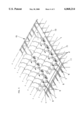
- FIG. 2 shows a plan view onto a floor grid structure with stringers and adapters according to the invention as shown in FIG. 1;
- FIG. 3 is a sectional view along section line III--III in FIG. 4 illustrating the mounting of rollers with an adapter in a stringer according to the invention for permitting freight containers or seat carrying pallets to roll along on the rollers mounted in the stringers;
- FIG. 4 is a view similar to FIG. 2, however showing the floor grid structure equipped with adapters for the mounting of rollers in the stringers and with conventional latch carriers;
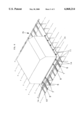
- FIG. 5 is a perspective view of seat pallets carrying passenger seats secured to a floor grid structure with stringers according to the invention.
- FIG. 6 is a perspective view similar to FIG. 4, but showing a freight container instead of a seat pallet.
- a floor grid FG is formed of supporting cross-joists 11 and stringers 5 according to the invention extending in the direction of the longitudinal aircraft axis.
- the stringers 5 are secured to the cross-joists 11 by gusset brackets 11A and welding and/or screws or rivets 6, 11B.
- the joists 11 extend cross-wise to the longitudinal aircraft axis. Normally, the crossing angle between joists 11 and stringers 5 will be 90°, but the invention is not limited to that angle.
- Each stringer 5 has, according to the invention, a U-cross-sectional configuration forming a U-rail, as best seen in FIGS. 1 and 3, and faces with its open side upwardly.
- Each stringer 5 of the invention is equipped with a seat rail 7 having an interrupted crown for cooperation with interlocking members 8/8A.
- the seat rail 7 is provided either with a groove or with a tongue for the cooperation with the interlocking members 8/8A and/or with adapters 4, 13.
- the seat rail 7 is an integral part of the bottom web of the U-rail 5, as will be described in more detail below.
- one of the interlocking members 8 or 8A is part of an adapter 4 which can be inserted in the stringer 5 in any position along the length of the seat rail 7 in the stringer 5 at spacings or intervals of about one inch provided in the crown of the seat rail 7 as best seen in FIGS. 2 and 4.
- the interlocking members are then fixed in position by moving them for about one half inch in the length direction of the stringers 5 in parallel to the longitudinal aircraft axis, thereby interlocking in the crown of the seat rail 7, which according to the invention is an integral or attached part of the present stringers 5.
- the interlocking members 8/8A include a conventional shear pin system 8A that is pressed downwardly for the interlocking with the crown of the seat rail crown 7.
- FIG. 1 shows an embodiment in which a support 1 is a pallet carrying aircraft passenger seats S best seen in FIG. 5.
- a latching mechanism 2 secures the pallet 1 with the help of a bolt connecter 3 to an adapter 4 that fits slidably into the U-cross-sectional configuration of the respective stringer 5.
- the adapter is equipped with lateral guide ribs 4A which slidingly engage the inner wall surface of the respective stringer 5. Once in the proper position, the adapter 4 is interlocked with the crown in the seat rail 7.
- the stringers 5 are preferably equipped with outwardly extending lateral flanges 9 to which floor panels 10 are mounted.
- Each stringer has a U-rail cross-section with a bottom web flanked by lateral side walls to the outside of which the flanges 9 are secured.
- the seat rail 7 is secured to the bottom web of the U-rail section of the stringer 5, either as an interal part of the bottom web, or by screws, rivets, welding or the like.
- the locking members 8/8A as such are conventional and are used in aircraft on seat rails. Such locking members are able to fix roller carriers 13 shown in FIG. 4 or latch carriers 14 also shown in FIG. 4.
- the present adapter 4 shown in FIG. 1 secures a seat pallet 1 to the floor. Even seats S may be directly secured to the crown of the seat rail 7 by such conventional locking members. However, in FIG. 1, a seat leg is secured to the adapter 4 through the elements 2 and 3 as described.
- FIG. 3 illustrates an embodiment wherein the roller carrier 13 is constructed as an adapter.
- the roller carrier 13 which carries at least one roller 12 functions insofar as an adapter as it permits securing the roller 12 to the crown of the seat rail 7 at the bottom of the U-rail forming the present stringers 5.
- FIG. 4 shows the adapters or roller carriers 13 secured to stringers 5 by the above mentioned locking members 8/8A. Either pallets or containers may now roll on these recessed rollers 12. The recessing gains up to 4 inches in the loading space height.
- FIG. 4 also shows latch carriers 14 secured to the crown of the seat rail 7 of the present stringers 5 by the above mentioned locking members 8/8A.
Abstract
Description
Claims (14)
Applications Claiming Priority (2)
| Application Number | Priority Date | Filing Date | Title |
|---|---|---|---|
| DE19700543 | 1997-01-10 | ||
| DE19700543 | 1997-01-10 |
Publications (1)
| Publication Number | Publication Date |
|---|---|
| US6068214A true US6068214A (en) | 2000-05-30 |
Family
ID=7817057
Family Applications (1)
| Application Number | Title | Priority Date | Filing Date |
|---|---|---|---|
| US09/005,552 Expired - Fee Related US6068214A (en) | 1997-01-10 | 1998-01-12 | System for securing a support to an aircraft floor |
Country Status (3)
| Country | Link |
|---|---|
| US (1) | US6068214A (en) |
| EP (1) | EP0853039B1 (en) |
| DE (2) | DE59709904D1 (en) |
Cited By (29)
| Publication number | Priority date | Publication date | Assignee | Title |
|---|---|---|---|---|
| US20040021039A1 (en) * | 2002-08-01 | 2004-02-05 | Jones Gary E. | Snap-on sidewall assembly |
| US20040216982A1 (en) * | 2003-04-30 | 2004-11-04 | Thomas Huber | Conveyor apparatus on a cargo deck of an aircraft |
| US20050072897A1 (en) * | 2003-09-23 | 2005-04-07 | Fanucci Jerome P. | Foundation adapter system |
| US20050133666A1 (en) * | 2003-12-19 | 2005-06-23 | Ingo Zerner | Seat mounting rail, particularly for a commercial aircraft |
| US20050156095A1 (en) * | 2003-12-19 | 2005-07-21 | Alexei Vichniakov | Seat mounting rail, particularly for a commercial aircraft |
| US20050190111A1 (en) * | 2000-07-18 | 2005-09-01 | King Patrick F. | Wireless communication device and method |
| US20050211836A1 (en) * | 2004-03-29 | 2005-09-29 | Frantz Walter F | Payload to support track interface and fitting apparatus and methods |
| US20050211840A1 (en) * | 2004-03-29 | 2005-09-29 | Grether Martin R | Adaptable payload enabling architecture |
| US20050211833A1 (en) * | 2004-03-29 | 2005-09-29 | Frantz Walter F | Non-protruding seat track apparatus and methods |
| US20050211844A1 (en) * | 2004-02-13 | 2005-09-29 | Airbus France | Seat rail for aircraft cabin and method of manufacturing such a rail |
| US20060006283A1 (en) * | 2004-07-08 | 2006-01-12 | Airbus France | Cockpit floor for aircraft |
| US20060006284A1 (en) * | 2004-07-08 | 2006-01-12 | Airbus France | Floor for aircraft |
| US20060088725A1 (en) * | 2004-10-26 | 2006-04-27 | Ruggiero Peter F | Corrosion-resistant coating for metal substrate |
| US20060292392A1 (en) * | 2004-10-26 | 2006-12-28 | Froning Marc J | Corrosion-resistant coating for metal substrate |
| US7411552B2 (en) | 2000-07-18 | 2008-08-12 | Mineral Lassen Llc | Grounded antenna for a wireless communication device and method |
| US20080277531A1 (en) * | 2007-05-11 | 2008-11-13 | The Boeing Company | Hybrid Composite Panel Systems and Methods |
| US20090166472A1 (en) * | 2007-12-27 | 2009-07-02 | Manfred Kook | Floor plate for covering a floor framework in an aircraft |
| JP2009534243A (en) * | 2006-04-20 | 2009-09-24 | エアバス フランス | Aircraft floors, the use of such floors and sections of aircraft comprising such floors |
| US20090324356A1 (en) * | 2006-03-30 | 2009-12-31 | Goodrich Corporation | Air cargo centerline restraint system having restraints mounted over floor joists outside the wingbox area for lateral support |
| US20100314495A1 (en) * | 2008-01-04 | 2010-12-16 | Airbus Operations (S.A.S.) | Device for attaching a piece of furniture to the floor of an aircraft |
| US20120074259A1 (en) * | 2009-01-29 | 2012-03-29 | Benoit Demont | Airframe including crossmembers for fixing seats |
| US20120235453A1 (en) * | 2011-03-15 | 2012-09-20 | Be Aerospace, Inc. | Plinth-mounted seat assembly and mounting sub-assemblies |
| USRE43683E1 (en) | 2000-07-18 | 2012-09-25 | Mineral Lassen Llc | Wireless communication device and method for discs |
| US20130189862A1 (en) * | 2011-08-03 | 2013-07-25 | Rittal Gmbh & Co., Kg | Busbar adapter comprising a mounting rail for attaching a switching device |
| US20140131519A1 (en) * | 2012-11-14 | 2014-05-15 | Airbus Operations Gmbh | Fastening arrangement for attaching a floor |
| US10046847B2 (en) * | 2014-06-23 | 2018-08-14 | Greenpoint Technologies, Inc. | Aircraft interior flooring systems |
| US10351244B2 (en) * | 2013-07-19 | 2019-07-16 | British Airways Plc | Aircraft passenger seat fixing systems and arrangements |
| US20210237878A1 (en) * | 2018-04-23 | 2021-08-05 | Moose Manufacturing Llc | System and Method for Mounting Items to an Aircraft Floor |
| US20220033059A1 (en) * | 2018-11-19 | 2022-02-03 | The Boeing Company | Shear ties for aircraft wing |
Families Citing this family (2)
| Publication number | Priority date | Publication date | Assignee | Title |
|---|---|---|---|---|
| DE19923489A1 (en) * | 1999-05-21 | 2000-11-30 | Daimler Chrysler Aerospace | Device for transporting and securing pallets equipped with freight containers or seats in an aircraft |
| DE102013104539A1 (en) | 2013-05-03 | 2014-11-06 | Telair International Gmbh | Pallet, cargo deck with a corresponding pallet and procedure for converting a cargo plane |
Citations (10)
| Publication number | Priority date | Publication date | Assignee | Title |
|---|---|---|---|---|
| US2625118A (en) * | 1949-03-22 | 1953-01-13 | Lockheed Aircraft Corp | Aircraft cargo floor |
| US2735377A (en) * | 1956-02-21 | Cargo tie-down | ||
| CH349493A (en) * | 1958-03-24 | 1960-10-15 | Park Ian Edward Stewart | Aerodyne and method of activating this aerodyne |
| US3381921A (en) * | 1967-01-03 | 1968-05-07 | Boeing Co | Quick change system for passenger and cargo carrying aircraft |
| US3612316A (en) * | 1969-12-22 | 1971-10-12 | Mc Donnell Douglas Corp | Cargo loading and restraint system |
| US3753541A (en) * | 1971-09-02 | 1973-08-21 | Mc Donnell Douglas Corp | Cargo roller assembly |
| US4185799A (en) * | 1978-03-14 | 1980-01-29 | Boeing Commercial Airplane Company | Aircraft partition mounting assembly |
| US4234278A (en) * | 1978-10-31 | 1980-11-18 | Electro-Pneumatic International Gmbh | Locking devices for cargo and the like |
| GB2167354A (en) * | 1984-11-23 | 1986-05-29 | Fruehauf Corp | Cargo tie-down device |
| US4696609A (en) * | 1986-04-21 | 1987-09-29 | Ancra Corporation | Pallet restraint mechanism for cargo loading system |
Family Cites Families (3)
| Publication number | Priority date | Publication date | Assignee | Title |
|---|---|---|---|---|
| US3480239A (en) * | 1967-02-23 | 1969-11-25 | Tridair Industries | Quick change system |
| US5131606A (en) * | 1991-04-01 | 1992-07-21 | Arnold Nordstrom | Seat pallet and cargo pallet restraining system |
| US5383630A (en) * | 1994-03-17 | 1995-01-24 | Teleflex Incorporated | Main deck quick change cargo system |
-
1997
- 1997-12-17 DE DE59709904T patent/DE59709904D1/en not_active Expired - Lifetime
- 1997-12-17 EP EP97122223A patent/EP0853039B1/en not_active Expired - Lifetime
- 1997-12-19 DE DE19756882A patent/DE19756882A1/en not_active Withdrawn
-
1998
- 1998-01-12 US US09/005,552 patent/US6068214A/en not_active Expired - Fee Related
Patent Citations (10)
| Publication number | Priority date | Publication date | Assignee | Title |
|---|---|---|---|---|
| US2735377A (en) * | 1956-02-21 | Cargo tie-down | ||
| US2625118A (en) * | 1949-03-22 | 1953-01-13 | Lockheed Aircraft Corp | Aircraft cargo floor |
| CH349493A (en) * | 1958-03-24 | 1960-10-15 | Park Ian Edward Stewart | Aerodyne and method of activating this aerodyne |
| US3381921A (en) * | 1967-01-03 | 1968-05-07 | Boeing Co | Quick change system for passenger and cargo carrying aircraft |
| US3612316A (en) * | 1969-12-22 | 1971-10-12 | Mc Donnell Douglas Corp | Cargo loading and restraint system |
| US3753541A (en) * | 1971-09-02 | 1973-08-21 | Mc Donnell Douglas Corp | Cargo roller assembly |
| US4185799A (en) * | 1978-03-14 | 1980-01-29 | Boeing Commercial Airplane Company | Aircraft partition mounting assembly |
| US4234278A (en) * | 1978-10-31 | 1980-11-18 | Electro-Pneumatic International Gmbh | Locking devices for cargo and the like |
| GB2167354A (en) * | 1984-11-23 | 1986-05-29 | Fruehauf Corp | Cargo tie-down device |
| US4696609A (en) * | 1986-04-21 | 1987-09-29 | Ancra Corporation | Pallet restraint mechanism for cargo loading system |
Cited By (65)
| Publication number | Priority date | Publication date | Assignee | Title |
|---|---|---|---|---|
| US7411552B2 (en) | 2000-07-18 | 2008-08-12 | Mineral Lassen Llc | Grounded antenna for a wireless communication device and method |
| US7397438B2 (en) | 2000-07-18 | 2008-07-08 | Mineral Lassen Llc | Wireless communication device and method |
| US20050190111A1 (en) * | 2000-07-18 | 2005-09-01 | King Patrick F. | Wireless communication device and method |
| USRE43683E1 (en) | 2000-07-18 | 2012-09-25 | Mineral Lassen Llc | Wireless communication device and method for discs |
| US20070001916A1 (en) * | 2000-07-18 | 2007-01-04 | Mineral Lassen Llc | Wireless communication device and method |
| US7460078B2 (en) | 2000-07-18 | 2008-12-02 | Mineral Lassen Llc | Wireless communication device and method |
| US6712316B2 (en) * | 2002-08-01 | 2004-03-30 | The Boeing Company | Snap-on sidewall assembly |
| US20040021039A1 (en) * | 2002-08-01 | 2004-02-05 | Jones Gary E. | Snap-on sidewall assembly |
| US20040216982A1 (en) * | 2003-04-30 | 2004-11-04 | Thomas Huber | Conveyor apparatus on a cargo deck of an aircraft |
| US7007786B2 (en) | 2003-04-30 | 2006-03-07 | Telair International Gmbh | Conveyor apparatus on a cargo deck of an aircraft |
| US8172195B2 (en) * | 2003-09-23 | 2012-05-08 | Kazak Composites, Incorporated | Foundation adapter system |
| US20050072897A1 (en) * | 2003-09-23 | 2005-04-07 | Fanucci Jerome P. | Foundation adapter system |
| US20050156095A1 (en) * | 2003-12-19 | 2005-07-21 | Alexei Vichniakov | Seat mounting rail, particularly for a commercial aircraft |
| US7207756B2 (en) * | 2003-12-19 | 2007-04-24 | Airbus Deutschland Gmbh | Seat mounting rail, particularly for a commercial aircraft |
| US20050133666A1 (en) * | 2003-12-19 | 2005-06-23 | Ingo Zerner | Seat mounting rail, particularly for a commercial aircraft |
| US7100885B2 (en) * | 2003-12-19 | 2006-09-05 | Airbus Deutschland Gmbh | Seat mounting rail, particularly for a commercial aircraft |
| US20050211844A1 (en) * | 2004-02-13 | 2005-09-29 | Airbus France | Seat rail for aircraft cabin and method of manufacturing such a rail |
| US7163178B2 (en) | 2004-02-13 | 2007-01-16 | Airbus France | Seat rail for aircraft cabin and method of manufacturing such a rail |
| US20060249616A1 (en) * | 2004-03-29 | 2006-11-09 | The Boeing Company | Payload to Support Track Interface and Fitting Apparatus and Methods |
| US7607613B2 (en) | 2004-03-29 | 2009-10-27 | The Boeing Company | Payload support track interface and fitting |
| JP4744508B2 (en) * | 2004-03-29 | 2011-08-10 | ザ・ボーイング・カンパニー | Configurations that allow adaptable payloads |
| US7195201B2 (en) | 2004-03-29 | 2007-03-27 | The Boeing Company | Adaptable payload enabling architecture |
| US20050211840A1 (en) * | 2004-03-29 | 2005-09-29 | Grether Martin R | Adaptable payload enabling architecture |
| US20050211836A1 (en) * | 2004-03-29 | 2005-09-29 | Frantz Walter F | Payload to support track interface and fitting apparatus and methods |
| JP2007530365A (en) * | 2004-03-29 | 2007-11-01 | ザ・ボーイング・カンパニー | Configurations that allow adaptable payloads |
| US7506855B2 (en) * | 2004-03-29 | 2009-03-24 | The Boeing Company | Non-protruding seat track apparatus |
| US7370832B2 (en) | 2004-03-29 | 2008-05-13 | The Boeing Company | Payload to support track interface and fitting apparatus and methods |
| US20050211833A1 (en) * | 2004-03-29 | 2005-09-29 | Frantz Walter F | Non-protruding seat track apparatus and methods |
| WO2005095205A1 (en) * | 2004-03-29 | 2005-10-13 | The Boeing Company | Adaptable payload enabling architecture |
| US7413143B2 (en) | 2004-03-29 | 2008-08-19 | The Boeing Company | Payload to support track interface and fitting apparatus and methods |
| US20080277528A1 (en) * | 2004-03-29 | 2008-11-13 | The Boeing Company | Payload support track interface and fitting |
| US20060006283A1 (en) * | 2004-07-08 | 2006-01-12 | Airbus France | Cockpit floor for aircraft |
| US7475850B2 (en) * | 2004-07-08 | 2009-01-13 | Airbus France | Cockpit floor for aircraft |
| US7338013B2 (en) * | 2004-07-08 | 2008-03-04 | Airbus France | Floor for aircraft |
| US20060006284A1 (en) * | 2004-07-08 | 2006-01-12 | Airbus France | Floor for aircraft |
| US20060088725A1 (en) * | 2004-10-26 | 2006-04-27 | Ruggiero Peter F | Corrosion-resistant coating for metal substrate |
| US7229700B2 (en) | 2004-10-26 | 2007-06-12 | Basf Catalysts, Llc. | Corrosion-resistant coating for metal substrate |
| US20060292392A1 (en) * | 2004-10-26 | 2006-12-28 | Froning Marc J | Corrosion-resistant coating for metal substrate |
| US8066458B2 (en) | 2006-03-30 | 2011-11-29 | Goodrich Corporation | Air cargo centerline restraint system having restraints mounted over floor joists outside the wingbox area for lateral support |
| US8066459B2 (en) | 2006-03-30 | 2011-11-29 | Goodrich Corporation | Air cargo centerline restraint system having restraints mounted over floor joists outside the wingbox area for lateral support |
| US7922431B2 (en) | 2006-03-30 | 2011-04-12 | Goodrich Corporation | Air cargo centerline restraint system having restraints mounted over floor joists outside the wingbox area for lateral support |
| US20110150594A1 (en) * | 2006-03-30 | 2011-06-23 | Goodrich Corporation | Air Cargo Centerline Restraint System Having Restraints Mounted Over Floor Joists Outside the Wingbox Area for Lateral Support |
| US20110146045A1 (en) * | 2006-03-30 | 2011-06-23 | Goodrich Corporation | Air Cargo Centerline Restraint System Having Restraints Mounted Over Floor Joists Outside the Wingbox Area for Lateral Support |
| US20090324356A1 (en) * | 2006-03-30 | 2009-12-31 | Goodrich Corporation | Air cargo centerline restraint system having restraints mounted over floor joists outside the wingbox area for lateral support |
| RU2499729C2 (en) * | 2006-04-20 | 2013-11-27 | Эрбюс Франс | Aircraft freight compartment floor, application of said floor and aircraft section provided with such floor |
| JP2009534243A (en) * | 2006-04-20 | 2009-09-24 | エアバス フランス | Aircraft floors, the use of such floors and sections of aircraft comprising such floors |
| US20080277531A1 (en) * | 2007-05-11 | 2008-11-13 | The Boeing Company | Hybrid Composite Panel Systems and Methods |
| US20090166472A1 (en) * | 2007-12-27 | 2009-07-02 | Manfred Kook | Floor plate for covering a floor framework in an aircraft |
| US9284036B2 (en) * | 2007-12-27 | 2016-03-15 | Airbus Operations Gmbh | Floor plate for covering a floor framework in an aircraft |
| US8668181B2 (en) * | 2008-01-04 | 2014-03-11 | Airbus Operations S.A.S. | Device for attaching a piece of furniture to the floor of an aircraft |
| US20100314495A1 (en) * | 2008-01-04 | 2010-12-16 | Airbus Operations (S.A.S.) | Device for attaching a piece of furniture to the floor of an aircraft |
| US20120074259A1 (en) * | 2009-01-29 | 2012-03-29 | Benoit Demont | Airframe including crossmembers for fixing seats |
| US8523109B2 (en) * | 2009-01-29 | 2013-09-03 | Airbus Operations (S.A.S.) | Airframe including crossmembers for fixing seats |
| US9139303B2 (en) * | 2011-03-15 | 2015-09-22 | Be Aerospace, Inc. | Plinth-mounted seat assembly and mounting sub-assemblies |
| US20120235453A1 (en) * | 2011-03-15 | 2012-09-20 | Be Aerospace, Inc. | Plinth-mounted seat assembly and mounting sub-assemblies |
| US20130189862A1 (en) * | 2011-08-03 | 2013-07-25 | Rittal Gmbh & Co., Kg | Busbar adapter comprising a mounting rail for attaching a switching device |
| US8714991B2 (en) * | 2011-08-03 | 2014-05-06 | Rittal Gmbh & Co. Kg | Busbar adapter comprising a mounting rail for attaching a switching device |
| US20140131519A1 (en) * | 2012-11-14 | 2014-05-15 | Airbus Operations Gmbh | Fastening arrangement for attaching a floor |
| US9139282B2 (en) * | 2012-11-14 | 2015-09-22 | Airbus Operations Gmbh | Fastening arrangement for attaching a floor |
| US10351244B2 (en) * | 2013-07-19 | 2019-07-16 | British Airways Plc | Aircraft passenger seat fixing systems and arrangements |
| US10046847B2 (en) * | 2014-06-23 | 2018-08-14 | Greenpoint Technologies, Inc. | Aircraft interior flooring systems |
| US20210237878A1 (en) * | 2018-04-23 | 2021-08-05 | Moose Manufacturing Llc | System and Method for Mounting Items to an Aircraft Floor |
| US11772796B2 (en) * | 2018-04-23 | 2023-10-03 | Moose Manufacturing Llc | System and method for mounting items to an aircraft floor |
| US20220033059A1 (en) * | 2018-11-19 | 2022-02-03 | The Boeing Company | Shear ties for aircraft wing |
| US11772775B2 (en) * | 2018-11-19 | 2023-10-03 | The Boeing Company | Shear ties for aircraft wing |
Also Published As
| Publication number | Publication date |
|---|---|
| DE59709904D1 (en) | 2003-05-28 |
| EP0853039A2 (en) | 1998-07-15 |
| EP0853039B1 (en) | 2003-04-23 |
| EP0853039A3 (en) | 1999-09-08 |
| DE19756882A1 (en) | 1998-07-16 |
Similar Documents
| Publication | Publication Date | Title |
|---|---|---|
| US6068214A (en) | System for securing a support to an aircraft floor | |
| US8006444B2 (en) | System and method for fastening floor deck to semi-trailer cross members | |
| EP0338020B1 (en) | Method and apparatus to enhance intermodal containers for cargo transport | |
| US5752673A (en) | Passenger aircraft with increased passenger capacity | |
| US5513941A (en) | Rolling cargo apparatus | |
| US7665938B2 (en) | Coaxially mounted retracting guide and restraint for an air cargo system | |
| US4066227A (en) | Mezzanine structure for wide-bodied passenger aircraft | |
| EP2321167B1 (en) | Trailer load securement system | |
| US8066458B2 (en) | Air cargo centerline restraint system having restraints mounted over floor joists outside the wingbox area for lateral support | |
| US6517028B2 (en) | Freight loading system | |
| US4699337A (en) | Cargo handling system for aircraft | |
| US10518822B2 (en) | Inner wall system for cargo container | |
| EP2630037B1 (en) | System for overhead storage of cargo containers in upper lobe of aircraft | |
| US10960980B2 (en) | Side guide, side guide group, cargo deck, aircraft | |
| US6527487B2 (en) | Cargo control system | |
| US20220001984A1 (en) | System for transporting cargo in an aircraft passenger cabin | |
| US4428491A (en) | Freight container, in particular for air transport | |
| CN114080333A (en) | Changing structure of seat arrangement in vehicle compartment | |
| US8151714B2 (en) | Container support for freight wagon | |
| US6886797B2 (en) | Seat track assembly | |
| PL160693B1 (en) | Railway freight car | |
| EP0618130A1 (en) | Cargo support decks | |
| JP6975825B2 (en) | Boarding / alighting device and railroad vehicle equipped with it | |
| US1710737A (en) | Compartment freight car | |
| US2584885A (en) | Panel for box type vehicle bodies |
Legal Events
| Date | Code | Title | Description |
|---|---|---|---|
| AS | Assignment |
Owner name: DAIMLERCHRYSLER AEROSPACE, GERMANY Free format text: ASSIGNMENT OF ASSIGNORS INTEREST;ASSIGNORS:KOOK, MANFRED;SCHOPENHAUER, WOLFRAM;REEL/FRAME:010217/0595 Effective date: 19980112 |
|
| CC | Certificate of correction | ||
| FPAY | Fee payment |
Year of fee payment: 4 |
|
| FPAY | Fee payment |
Year of fee payment: 8 |
|
| FEPP | Fee payment procedure |
Free format text: PAYOR NUMBER ASSIGNED (ORIGINAL EVENT CODE: ASPN); ENTITY STATUS OF PATENT OWNER: LARGE ENTITY Free format text: PAYER NUMBER DE-ASSIGNED (ORIGINAL EVENT CODE: RMPN); ENTITY STATUS OF PATENT OWNER: LARGE ENTITY |
|
| REMI | Maintenance fee reminder mailed | ||
| LAPS | Lapse for failure to pay maintenance fees | ||
| STCH | Information on status: patent discontinuation |
Free format text: PATENT EXPIRED DUE TO NONPAYMENT OF MAINTENANCE FEES UNDER 37 CFR 1.362 |
|
| FP | Lapsed due to failure to pay maintenance fee |
Effective date: 20120530 |