US6061499A - Composite instantaneous water heater - Google Patents
Composite instantaneous water heater Download PDFInfo
- Publication number
- US6061499A US6061499A US09/048,526 US4852698A US6061499A US 6061499 A US6061499 A US 6061499A US 4852698 A US4852698 A US 4852698A US 6061499 A US6061499 A US 6061499A
- Authority
- US
- United States
- Prior art keywords
- pressure vessel
- water heater
- closure plate
- heat exchanger
- hot water
- Prior art date
- Legal status (The legal status is an assumption and is not a legal conclusion. Google has not performed a legal analysis and makes no representation as to the accuracy of the status listed.)
- Expired - Fee Related
Links
Images


Classifications
-
- F—MECHANICAL ENGINEERING; LIGHTING; HEATING; WEAPONS; BLASTING
- F24—HEATING; RANGES; VENTILATING
- F24H—FLUID HEATERS, e.g. WATER OR AIR HEATERS, HAVING HEAT-GENERATING MEANS, e.g. HEAT PUMPS, IN GENERAL
- F24H1/00—Water heaters, e.g. boilers, continuous-flow heaters or water-storage heaters
- F24H1/18—Water-storage heaters
- F24H1/181—Construction of the tank
Definitions
- This invention relates to water heaters and, more particularly, to instantaneous small capacity water heaters which are adapted to serve closely adjacent appliances that consume or dispense hot water.
- Small capacity, rapid response water heaters that are positioned closely adjacent the unit to be served are economical in that they are well insulated and are not subject to heat loss through long reaches of copper tubing prior to delivery to the appliance or hot water dispenser as contrasted to large capacity water heaters which are intended to serve a number of locations from a single station.
- Existing instantaneous heaters are constructed of stainless or porcelain steel which are either subject to corrosion or are expensive. In either case the water heaters are not particularly attractive.
- the water heater comprises an inner plastic pressure vessel for storing heated water.
- the pressure vessel has an access opening provided with a removable cover plate which mounts an electric resistance heating element so that the heating element may be mounted within the pressure vessel and retained therein by the closure fitting.
- An outer housing surrounds the inner plastic pressure vessel.
- a thermal insulating material such as a closed cell, foamed-in-place urethane is interposed between the inner plastic pressure vessel and the outer housing.
- the housing is provided with a removable closure cap so that access may be had to a space between the closure cap and the cover plate for servicing switching and thermostatic controls for the electric resistance heating element provided therein and for access to the electric resistance heater itself.
- the pressure vessel employed in this invention utilizes a rotationally molded liner with aluminum flanges at the polar ends which are integrally molded into the rotationally molded liner according to the teachings of U.S. Pat. No. 4,705,768.
- the rotationally molded liner is filament wound with continuous epoxy-impregnated fiberglass for pressurized applications.
- the outer plastic housing maybe formed by either rotational molding or blow molding techniques and the typical material for the liner and the housing is polyethylene.
- FIG. 1 is an elevational view of the inner plastic pressure vessel of this invention with a portion broken away to show details of construction;
- FIG. 2 is an end view of the pressure vessel
- FIG. 3 is an opposite end view of the pressure vessel
- FIG. 4 is a fragmentary elevational view, partly in section, of a rotational casting mold mounting arrangement for producing the inner plastic pressure vessel of this invention
- FIG. 5 is a fragmentary elevational view of the inner plastic pressure vessel of this invention.
- FIG. 6 is a perspective view of the pressure vessel mounted within an outer housing
- FIG. 7 is a view similar to a FIG. 6 but from a different perspective
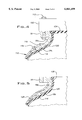
- FIG. 8 is a fragmentary elevational view, partly in section, of a rotational casting mounting arrangement for producing an inner plastic pressure vessel according to another aspect of this invention.
- FIG. 9 is a fragmentary elevational view of a pressure vessel according to a further aspect of this invention.
- the pressure vessel 10 includes a polyethylene wall portion 12 which is filament wound with continuous epoxy-impregnated glass fiber for pressurized applications according to well known prior art techniques.
- the polyethylene wall is desirably rotationally molded according to the teachings of U.S. Pat. No. 4,705,468, the subject matter of which is incorporated herein by reference.
- the polyethylene wall 12 may be formed by blow molding techniques as set forth in U.S. Pat. No. 4,589,563, the subject matter of which is incorporated herein by reference.
- the ends of the pressure vessel 10 are provided with metal cover plates 14 and 16 which are respectively mounted on metal flanges 18 and 20 by a plurality of bolts 22.
- the inner plastic pressure vessel 10 may be molded in a rotational casting machine as set forth in detail in U.S. Pat. No. 4,705,468.
- the molding apparatus comprises a mold arm assembly which includes upper and lower frame members (not shown). The frame members are rotated about a first axis. Mounting plates 100 are rotatably carried by each frame member and are driven to rotate about a second axis which is perpendicular to the first axis.
- a rotational casting mold 110 is mounted between the mounting plates 100 by a plurality of blots 112 which extend, for example, from the mounting plates 100 through the flange 18.
- the flange 18 has a cylindrical neck portion 18a provided with an annular tapered foot 18b.
- the tapered foot 18b is provided with a plurality of blind openings 114 therein which receive bolts 116 which pass through an upper rim portion 118 of the mold 110.
- the pressure vessel is molded by placing a charge of powdered thermoplastic resin in the mold 110 and rotating the mold about orthogonal axes. Heat is supplied so that the resin is fused in an even layer having a predetermined thickness.
- the application of heat to the mold causes the resin to melt or fuse, and the rotation of the mold causes the liquid resin to uniformly coat the interior of the mold cavity and the interior of the metal flanges 18 and 20 so that a liner 120 is formed having a uniform thickness.
- the liner 120 is adhered to the interior of the flanges 18 and 20.
- the smooth blending of the inside surface of the mold 110 into the plane of the tapered foot 18b provides a smooth, continuous surface.
- a completed pressure vessel 10 is provided by machining away a plug portion 124 of the liner 120 to form an access opening 126.
- the side wall of the liner 120 is helically wound with epoxy-impregnated filaments 128 to provide reinforcement for longitudinal and hoop stresses.
- Access openings are provided through the cover plate 14 to accommodate inlet and outlet piping 24 and 26, respectively, and for a pressure relief valve 28. It maybe noted that the outlet 26 extends upwardly in the pressure vessel to prevent air from being trapped in the tank. A number of additional access openings 30 are provided in the cover plate 16 to accommodate sensing equipment and heating elements (not shown).
- FIGS. 8 and 9 there is illustrated an alternate embodiment of the pressure vessel 10 wherein the liner 120a covers the upper face of the flange 18a to prevent liquid contained in the pressure vessel from contacting any portion of the metal flange 18a.
- a rotational casting mold 110 a is mounted between mounting plates 100a a by a plurality of bolts 112a which extend from the mounting plate 100a through the flange 18a. Spacers 150 are provided around the bolts 112a.
- a plastic liner 120a coats the inside surface of the mold 110a and the interior of the flange 18a including an upper surface portion 152 of the flange 18a.
- a liner plug 154 is machined away to provide the structure illustrated in FIG. 9.
- the liner 120a is helically wound with resin impregnated filaments 156 to provide reinforcement for longitudinal and hoop stresses in the completed pressure vessel.
- the pressure vessel 10 is mounted within an outer plastic housing 32.
- the housing 32 is preferably rotationally cast and has a generally cylindrical sidewall 34 which defines a centrally located saddle 36 for mounting the pressure vessel in a horizonal position.
- the sidewall 34 also defines molded-in support legs 38.
- the outer plastic housing 32 has an end wall 40 and an open, opposite end 42 which is closed by a removable cap 44.
- the saddle 36 mounts the pressure vessel 10 so that the pressure vessel 10 is substantially coaxially mounted in the outer plastic housing 32 and is spaced from the cylindrical sidewall of the housing.
- the cover plate 14, however, is positioned closely adjacent the bottom wall 40 while the cover plate 16 is spaced from the open end 42.
- a urethane foam insulation 50 (FIG. 7) is foamed in place through an aperture (not shown) in the outer housing 32.
- a suitable removable plug (not shown) is positioned in the open end 42 of the housing 32 in an abutting relationship to the cover plate to provide a space 52 between the cover plate 16 and the removable cap 44. The plug is removed after the urethane 50 is foamed in place. Access may then be had to the interior of the inner plastic pressure vessel 10 for servicing by removal of the cover plate 16.
- Various controls (not shown) maybe provided in the space such as sensing equipment, heating elements, thermostatic switches and the like.
Abstract
Description
Claims (9)
Priority Applications (1)
| Application Number | Priority Date | Filing Date | Title |
|---|---|---|---|
| US09/048,526 US6061499A (en) | 1997-03-31 | 1998-03-26 | Composite instantaneous water heater |
Applications Claiming Priority (2)
| Application Number | Priority Date | Filing Date | Title |
|---|---|---|---|
| US4289397P | 1997-03-31 | 1997-03-31 | |
| US09/048,526 US6061499A (en) | 1997-03-31 | 1998-03-26 | Composite instantaneous water heater |
Publications (1)
| Publication Number | Publication Date |
|---|---|
| US6061499A true US6061499A (en) | 2000-05-09 |
Family
ID=26719744
Family Applications (1)
| Application Number | Title | Priority Date | Filing Date |
|---|---|---|---|
| US09/048,526 Expired - Fee Related US6061499A (en) | 1997-03-31 | 1998-03-26 | Composite instantaneous water heater |
Country Status (1)
| Country | Link |
|---|---|
| US (1) | US6061499A (en) |
Cited By (28)
| Publication number | Priority date | Publication date | Assignee | Title |
|---|---|---|---|---|
| US6175689B1 (en) * | 1999-06-10 | 2001-01-16 | Byron Blanco, Jr. | In-line tankless electrical resistance water heater |
| US6240250B1 (en) * | 1999-06-10 | 2001-05-29 | Byron Blanco, Jr. | Compact in-line tankless double element water heater |
| US6366913B1 (en) * | 1998-10-21 | 2002-04-02 | Netscape Communications Corporation | Centralized directory services supporting dynamic group membership |
| US6470836B1 (en) * | 1998-06-15 | 2002-10-29 | Rheem Australia Pty Ltd. | Water jacket assembly |
| US20040122801A1 (en) * | 2002-12-18 | 2004-06-24 | International Business Machines Corporation | Method, system and program product for filtering an entry of data items |
| US6909843B1 (en) | 2004-02-24 | 2005-06-21 | Eemax Incorporated | Electric tankless water heater |
| US20060027673A1 (en) * | 2004-08-06 | 2006-02-09 | Fabrizio Edward V | Electric tankless water heater |
| US20090084330A1 (en) * | 2007-10-02 | 2009-04-02 | John Mark Kloster | Enclosure for marine water heaters |
| US20090205742A1 (en) * | 2008-02-20 | 2009-08-20 | Ming Kuo | Organic polymer coatings for water containers |
| US7690395B2 (en) | 2004-01-12 | 2010-04-06 | Masco Corporation Of Indiana | Multi-mode hands free automatic faucet |
| US8089473B2 (en) | 2006-04-20 | 2012-01-03 | Masco Corporation Of Indiana | Touch sensor |
| US8118240B2 (en) | 2006-04-20 | 2012-02-21 | Masco Corporation Of Indiana | Pull-out wand |
| US8162236B2 (en) | 2006-04-20 | 2012-04-24 | Masco Corporation Of Indiana | Electronic user interface for electronic mixing of water for residential faucets |
| CN102778038A (en) * | 2012-08-21 | 2012-11-14 | 山东浩歌工贸有限公司 | Inner container of water heater |
| US8365767B2 (en) | 2006-04-20 | 2013-02-05 | Masco Corporation Of Indiana | User interface for a faucet |
| US8376313B2 (en) | 2007-03-28 | 2013-02-19 | Masco Corporation Of Indiana | Capacitive touch sensor |
| US8469056B2 (en) | 2007-01-31 | 2013-06-25 | Masco Corporation Of Indiana | Mixing valve including a molded waterway assembly |
| US8561626B2 (en) | 2010-04-20 | 2013-10-22 | Masco Corporation Of Indiana | Capacitive sensing system and method for operating a faucet |
| US8577211B2 (en) | 2010-09-14 | 2013-11-05 | Eemax Incorporated | Heating element assembly for electric tankless liquid heater |
| US8613419B2 (en) | 2007-12-11 | 2013-12-24 | Masco Corporation Of Indiana | Capacitive coupling arrangement for a faucet |
| US8776817B2 (en) | 2010-04-20 | 2014-07-15 | Masco Corporation Of Indiana | Electronic faucet with a capacitive sensing system and a method therefor |
| US8944105B2 (en) | 2007-01-31 | 2015-02-03 | Masco Corporation Of Indiana | Capacitive sensing apparatus and method for faucets |
| US9175458B2 (en) | 2012-04-20 | 2015-11-03 | Delta Faucet Company | Faucet including a pullout wand with a capacitive sensing |
| US9243392B2 (en) | 2006-12-19 | 2016-01-26 | Delta Faucet Company | Resistive coupling for an automatic faucet |
| US9243756B2 (en) | 2006-04-20 | 2016-01-26 | Delta Faucet Company | Capacitive user interface for a faucet and method of forming |
| US20180347757A1 (en) * | 2015-11-25 | 2018-12-06 | United Technologies Corporation | Composite pressure vessel assembly with an integrated heating element |
| US10378790B2 (en) * | 2016-02-25 | 2019-08-13 | Xiamen Aquasu Electric Shower Co., Ltd | Boiling water heater |
| US11054173B2 (en) | 2017-12-06 | 2021-07-06 | A. O. Smith Corporation | Water heater with organic polymer coating |
Citations (10)
| Publication number | Priority date | Publication date | Assignee | Title |
|---|---|---|---|---|
| US1718866A (en) * | 1928-06-11 | 1929-06-25 | Barnett W Macy | Liquid heater |
| US2718583A (en) * | 1952-11-18 | 1955-09-20 | David B Noland | Water-heater tank of reinforced plastic and method and apparatus for making the same |
| US2877335A (en) * | 1955-09-14 | 1959-03-10 | Relf Victor Keith | Water heating and boiling water control apparatus |
| US3207358A (en) * | 1961-07-27 | 1965-09-21 | Gen Electric | Water storage tanks and methods of making the same |
| US3617700A (en) * | 1969-06-02 | 1971-11-02 | Torginol Ind Inc | Immersion heater |
| US4477399A (en) * | 1982-06-16 | 1984-10-16 | Gsw Inc. | Method and apparatus for manufacturing a foam insulated water heater |
| US4589563A (en) * | 1983-03-07 | 1986-05-20 | Quality Products, Inc. | High-pressure container and method of making the same |
| US4687905A (en) * | 1986-02-03 | 1987-08-18 | Emerson Electric Co. | Electric immersion heating element assembly for use with a plastic water heater tank |
| US4865014A (en) * | 1989-02-16 | 1989-09-12 | Nelson Thomas E | Water heater and method of fabricating same |
| US5220638A (en) * | 1991-09-30 | 1993-06-15 | Mor-Flo Industries, Inc. | Water heater with an improved thermostat mounting and a method of making such water heaters |
-
1998
- 1998-03-26 US US09/048,526 patent/US6061499A/en not_active Expired - Fee Related
Patent Citations (10)
| Publication number | Priority date | Publication date | Assignee | Title |
|---|---|---|---|---|
| US1718866A (en) * | 1928-06-11 | 1929-06-25 | Barnett W Macy | Liquid heater |
| US2718583A (en) * | 1952-11-18 | 1955-09-20 | David B Noland | Water-heater tank of reinforced plastic and method and apparatus for making the same |
| US2877335A (en) * | 1955-09-14 | 1959-03-10 | Relf Victor Keith | Water heating and boiling water control apparatus |
| US3207358A (en) * | 1961-07-27 | 1965-09-21 | Gen Electric | Water storage tanks and methods of making the same |
| US3617700A (en) * | 1969-06-02 | 1971-11-02 | Torginol Ind Inc | Immersion heater |
| US4477399A (en) * | 1982-06-16 | 1984-10-16 | Gsw Inc. | Method and apparatus for manufacturing a foam insulated water heater |
| US4589563A (en) * | 1983-03-07 | 1986-05-20 | Quality Products, Inc. | High-pressure container and method of making the same |
| US4687905A (en) * | 1986-02-03 | 1987-08-18 | Emerson Electric Co. | Electric immersion heating element assembly for use with a plastic water heater tank |
| US4865014A (en) * | 1989-02-16 | 1989-09-12 | Nelson Thomas E | Water heater and method of fabricating same |
| US5220638A (en) * | 1991-09-30 | 1993-06-15 | Mor-Flo Industries, Inc. | Water heater with an improved thermostat mounting and a method of making such water heaters |
Cited By (51)
| Publication number | Priority date | Publication date | Assignee | Title |
|---|---|---|---|---|
| US6470836B1 (en) * | 1998-06-15 | 2002-10-29 | Rheem Australia Pty Ltd. | Water jacket assembly |
| US6366913B1 (en) * | 1998-10-21 | 2002-04-02 | Netscape Communications Corporation | Centralized directory services supporting dynamic group membership |
| US6240250B1 (en) * | 1999-06-10 | 2001-05-29 | Byron Blanco, Jr. | Compact in-line tankless double element water heater |
| US6175689B1 (en) * | 1999-06-10 | 2001-01-16 | Byron Blanco, Jr. | In-line tankless electrical resistance water heater |
| US20040122801A1 (en) * | 2002-12-18 | 2004-06-24 | International Business Machines Corporation | Method, system and program product for filtering an entry of data items |
| US7690395B2 (en) | 2004-01-12 | 2010-04-06 | Masco Corporation Of Indiana | Multi-mode hands free automatic faucet |
| US9243391B2 (en) | 2004-01-12 | 2016-01-26 | Delta Faucet Company | Multi-mode hands free automatic faucet |
| US8528579B2 (en) | 2004-01-12 | 2013-09-10 | Masco Corporation Of Indiana | Multi-mode hands free automatic faucet |
| US8280236B2 (en) | 2004-02-24 | 2012-10-02 | Eemax Incorporated | Electric tankless water heater |
| US7567751B2 (en) | 2004-02-24 | 2009-07-28 | Eemax, Inc. | Electric tankless water heater |
| US6909843B1 (en) | 2004-02-24 | 2005-06-21 | Eemax Incorporated | Electric tankless water heater |
| US20090285569A1 (en) * | 2004-02-24 | 2009-11-19 | Eemax, Inc | Electric tankless water heater |
| US20050185942A1 (en) * | 2004-02-24 | 2005-08-25 | Fabrizio Edward V. | Electric tankless water heater |
| US20110013893A1 (en) * | 2004-02-24 | 2011-01-20 | Eemax, Inc. | Electric tankless water heater |
| US8064758B2 (en) | 2004-02-24 | 2011-11-22 | Eemax, Inc. | Electric tankless water heater |
| US7779790B2 (en) | 2004-08-06 | 2010-08-24 | Eemax, Inc. | Electric tankless water heater |
| US20100278519A1 (en) * | 2004-08-06 | 2010-11-04 | Edward Vincent Fabrizio | Electric tankless water heater |
| US20060027673A1 (en) * | 2004-08-06 | 2006-02-09 | Fabrizio Edward V | Electric tankless water heater |
| US8104434B2 (en) | 2004-08-06 | 2012-01-31 | Eemax, Inc. | Electric tankless water heater |
| US8162236B2 (en) | 2006-04-20 | 2012-04-24 | Masco Corporation Of Indiana | Electronic user interface for electronic mixing of water for residential faucets |
| US8365767B2 (en) | 2006-04-20 | 2013-02-05 | Masco Corporation Of Indiana | User interface for a faucet |
| US8118240B2 (en) | 2006-04-20 | 2012-02-21 | Masco Corporation Of Indiana | Pull-out wand |
| US8243040B2 (en) | 2006-04-20 | 2012-08-14 | Masco Corporation Of Indiana | Touch sensor |
| US9856634B2 (en) | 2006-04-20 | 2018-01-02 | Delta Faucet Company | Fluid delivery device with an in-water capacitive sensor |
| US10698429B2 (en) | 2006-04-20 | 2020-06-30 | Delta Faucet Company | Electronic user interface for electronic mixing of water for residential faucets |
| US9715238B2 (en) | 2006-04-20 | 2017-07-25 | Delta Faucet Company | Electronic user interface for electronic mixing of water for residential faucets |
| US9228329B2 (en) | 2006-04-20 | 2016-01-05 | Delta Faucet Company | Pull-out wand |
| US9285807B2 (en) | 2006-04-20 | 2016-03-15 | Delta Faucet Company | Electronic user interface for electronic mixing of water for residential faucets |
| US9243756B2 (en) | 2006-04-20 | 2016-01-26 | Delta Faucet Company | Capacitive user interface for a faucet and method of forming |
| US8089473B2 (en) | 2006-04-20 | 2012-01-03 | Masco Corporation Of Indiana | Touch sensor |
| US11886208B2 (en) | 2006-04-20 | 2024-01-30 | Delta Faucet Company | Electronic user interface for electronic mixing of water for residential faucets |
| US9243392B2 (en) | 2006-12-19 | 2016-01-26 | Delta Faucet Company | Resistive coupling for an automatic faucet |
| US8127782B2 (en) | 2006-12-19 | 2012-03-06 | Jonte Patrick B | Multi-mode hands free automatic faucet |
| US8844564B2 (en) | 2006-12-19 | 2014-09-30 | Masco Corporation Of Indiana | Multi-mode hands free automatic faucet |
| US8944105B2 (en) | 2007-01-31 | 2015-02-03 | Masco Corporation Of Indiana | Capacitive sensing apparatus and method for faucets |
| US8469056B2 (en) | 2007-01-31 | 2013-06-25 | Masco Corporation Of Indiana | Mixing valve including a molded waterway assembly |
| US8376313B2 (en) | 2007-03-28 | 2013-02-19 | Masco Corporation Of Indiana | Capacitive touch sensor |
| US20090084330A1 (en) * | 2007-10-02 | 2009-04-02 | John Mark Kloster | Enclosure for marine water heaters |
| US9315976B2 (en) | 2007-12-11 | 2016-04-19 | Delta Faucet Company | Capacitive coupling arrangement for a faucet |
| US8613419B2 (en) | 2007-12-11 | 2013-12-24 | Masco Corporation Of Indiana | Capacitive coupling arrangement for a faucet |
| US20090205742A1 (en) * | 2008-02-20 | 2009-08-20 | Ming Kuo | Organic polymer coatings for water containers |
| US8277912B2 (en) | 2008-02-20 | 2012-10-02 | Aos Holding Company | Organic polymer coatings for water containers |
| US9394675B2 (en) | 2010-04-20 | 2016-07-19 | Delta Faucet Company | Capacitive sensing system and method for operating a faucet |
| US8776817B2 (en) | 2010-04-20 | 2014-07-15 | Masco Corporation Of Indiana | Electronic faucet with a capacitive sensing system and a method therefor |
| US8561626B2 (en) | 2010-04-20 | 2013-10-22 | Masco Corporation Of Indiana | Capacitive sensing system and method for operating a faucet |
| US8577211B2 (en) | 2010-09-14 | 2013-11-05 | Eemax Incorporated | Heating element assembly for electric tankless liquid heater |
| US9175458B2 (en) | 2012-04-20 | 2015-11-03 | Delta Faucet Company | Faucet including a pullout wand with a capacitive sensing |
| CN102778038A (en) * | 2012-08-21 | 2012-11-14 | 山东浩歌工贸有限公司 | Inner container of water heater |
| US20180347757A1 (en) * | 2015-11-25 | 2018-12-06 | United Technologies Corporation | Composite pressure vessel assembly with an integrated heating element |
| US10378790B2 (en) * | 2016-02-25 | 2019-08-13 | Xiamen Aquasu Electric Shower Co., Ltd | Boiling water heater |
| US11054173B2 (en) | 2017-12-06 | 2021-07-06 | A. O. Smith Corporation | Water heater with organic polymer coating |
Similar Documents
| Publication | Publication Date | Title |
|---|---|---|
| US6061499A (en) | Composite instantaneous water heater | |
| CA2185492C (en) | Water heater having molded plastic storage tank, and associated fabrication methods | |
| EP0223367B1 (en) | Apparatus for rotationally casting a plastic tank liner having an access fitting | |
| US6267261B1 (en) | Cavitated insulating support base for hot water tank | |
| JP3561239B2 (en) | Hot water storage tank | |
| KR100387321B1 (en) | Heating and / or cooling accumulator-exchanger | |
| US6516141B1 (en) | Apparatus and method for protecting a heating tank assembly of a hot water dispenser | |
| KR100597552B1 (en) | Hot-water appliance with vacuum insulation, to be connected to the water main | |
| CH637568A5 (en) | APPARATUS FOR THE MANUFACTURE OF A BOTTLE BY BLOWING. | |
| GB2059027A (en) | Lined metal tank with heat shield indirect fired water heater and method of making same | |
| CA2248865C (en) | Continuously cleaned pressureless water heater with immersed copper fluid coil | |
| CA2542572C (en) | Condensing gas fired water heater | |
| CA2276433C (en) | Bottom pad/foam dam apparatus for water heaters | |
| EP0134363A2 (en) | Container for use as a pressure vessel in a hot water system | |
| US5220638A (en) | Water heater with an improved thermostat mounting and a method of making such water heaters | |
| US6412448B1 (en) | Water heater construction | |
| JP2004197960A (en) | Hot water storage tank, and molded heat insulation member for hot water storage tank | |
| KR101000916B1 (en) | The apparatus for providing beverage | |
| CN101852486B (en) | Water storage type electric water heater | |
| GB2483228A (en) | Hot water storage cylinder | |
| JP3682204B2 (en) | Method of manufacturing a water heater | |
| WO2005084912A1 (en) | Method of producing a boiler comprising a perforated reinforcing by rotational moulding | |
| US2735925A (en) | Water heater | |
| FI79655B (en) | ANORDNING FOER TORKANDE AV TRYCKLUFT. | |
| JPH11245929A (en) | Resin-made tank and water discharger |
Legal Events
| Date | Code | Title | Description |
|---|---|---|---|
| AS | Assignment |
Owner name: STRUCTURAL NORTH AMERICA, OHIO Free format text: ASSIGNMENT OF ASSIGNORS INTEREST;ASSIGNOR:HLEBOVY, JAMES C.;REEL/FRAME:009067/0141 Effective date: 19980313 |
|
| AS | Assignment |
Owner name: ESSEF CORPORATION, OHIO Free format text: ASSIGNMENT OF ASSIGNORS INTEREST;ASSIGNOR:HLEBOVY, JAMES C.;REEL/FRAME:009203/0180 Effective date: 19980514 |
|
| FPAY | Fee payment |
Year of fee payment: 4 |
|
| FPAY | Fee payment |
Year of fee payment: 8 |
|
| REMI | Maintenance fee reminder mailed | ||
| LAPS | Lapse for failure to pay maintenance fees | ||
| STCH | Information on status: patent discontinuation |
Free format text: PATENT EXPIRED DUE TO NONPAYMENT OF MAINTENANCE FEES UNDER 37 CFR 1.362 |
|
| FP | Lapsed due to failure to pay maintenance fee |
Effective date: 20120509 |