US6057149A - Microscale devices and reactions in microscale devices - Google Patents
Microscale devices and reactions in microscale devices Download PDFInfo
- Publication number
- US6057149A US6057149A US08/529,293 US52929395A US6057149A US 6057149 A US6057149 A US 6057149A US 52929395 A US52929395 A US 52929395A US 6057149 A US6057149 A US 6057149A
- Authority
- US
- United States
- Prior art keywords
- microdroplet
- silicon
- channel
- liquid
- microdroplets
- Prior art date
- Legal status (The legal status is an assumption and is not a legal conclusion. Google has not performed a legal analysis and makes no representation as to the accuracy of the status listed.)
- Expired - Lifetime
Links
Images


Classifications
-
- F—MECHANICAL ENGINEERING; LIGHTING; HEATING; WEAPONS; BLASTING
- F15—FLUID-PRESSURE ACTUATORS; HYDRAULICS OR PNEUMATICS IN GENERAL
- F15B—SYSTEMS ACTING BY MEANS OF FLUIDS IN GENERAL; FLUID-PRESSURE ACTUATORS, e.g. SERVOMOTORS; DETAILS OF FLUID-PRESSURE SYSTEMS, NOT OTHERWISE PROVIDED FOR
- F15B13/00—Details of servomotor systems ; Valves for servomotor systems
- F15B13/02—Fluid distribution or supply devices characterised by their adaptation to the control of servomotors
- F15B13/06—Fluid distribution or supply devices characterised by their adaptation to the control of servomotors for use with two or more servomotors
- F15B13/08—Assemblies of units, each for the control of a single servomotor only
- F15B13/0803—Modular units
- F15B13/0807—Manifolds
-
- B—PERFORMING OPERATIONS; TRANSPORTING
- B01—PHYSICAL OR CHEMICAL PROCESSES OR APPARATUS IN GENERAL
- B01F—MIXING, e.g. DISSOLVING, EMULSIFYING OR DISPERSING
- B01F25/00—Flow mixers; Mixers for falling materials, e.g. solid particles
- B01F25/14—Mixing drops, droplets or bodies of liquid which flow together or contact each other
-
- B—PERFORMING OPERATIONS; TRANSPORTING
- B01—PHYSICAL OR CHEMICAL PROCESSES OR APPARATUS IN GENERAL
- B01F—MIXING, e.g. DISSOLVING, EMULSIFYING OR DISPERSING
- B01F25/00—Flow mixers; Mixers for falling materials, e.g. solid particles
- B01F25/30—Injector mixers
- B01F25/31—Injector mixers in conduits or tubes through which the main component flows
-
- B—PERFORMING OPERATIONS; TRANSPORTING
- B01—PHYSICAL OR CHEMICAL PROCESSES OR APPARATUS IN GENERAL
- B01F—MIXING, e.g. DISSOLVING, EMULSIFYING OR DISPERSING
- B01F33/00—Other mixers; Mixing plants; Combinations of mixers
- B01F33/30—Micromixers
- B01F33/302—Micromixers the materials to be mixed flowing in the form of droplets
- B01F33/3021—Micromixers the materials to be mixed flowing in the form of droplets the components to be mixed being combined in a single independent droplet, e.g. these droplets being divided by a non-miscible fluid or consisting of independent droplets
-
- B—PERFORMING OPERATIONS; TRANSPORTING
- B01—PHYSICAL OR CHEMICAL PROCESSES OR APPARATUS IN GENERAL
- B01F—MIXING, e.g. DISSOLVING, EMULSIFYING OR DISPERSING
- B01F33/00—Other mixers; Mixing plants; Combinations of mixers
- B01F33/30—Micromixers
- B01F33/302—Micromixers the materials to be mixed flowing in the form of droplets
- B01F33/3022—Micromixers the materials to be mixed flowing in the form of droplets the components being formed by independent droplets which are alternated, the mixing of the components being achieved by diffusion between droplets
-
- B—PERFORMING OPERATIONS; TRANSPORTING
- B01—PHYSICAL OR CHEMICAL PROCESSES OR APPARATUS IN GENERAL
- B01F—MIXING, e.g. DISSOLVING, EMULSIFYING OR DISPERSING
- B01F33/00—Other mixers; Mixing plants; Combinations of mixers
- B01F33/30—Micromixers
- B01F33/3039—Micromixers with mixing achieved by diffusion between layers
-
- B—PERFORMING OPERATIONS; TRANSPORTING
- B01—PHYSICAL OR CHEMICAL PROCESSES OR APPARATUS IN GENERAL
- B01F—MIXING, e.g. DISSOLVING, EMULSIFYING OR DISPERSING
- B01F35/00—Accessories for mixers; Auxiliary operations or auxiliary devices; Parts or details of general application
- B01F35/71—Feed mechanisms
- B01F35/717—Feed mechanisms characterised by the means for feeding the components to the mixer
- B01F35/7172—Feed mechanisms characterised by the means for feeding the components to the mixer using capillary forces
-
- C—CHEMISTRY; METALLURGY
- C12—BIOCHEMISTRY; BEER; SPIRITS; WINE; VINEGAR; MICROBIOLOGY; ENZYMOLOGY; MUTATION OR GENETIC ENGINEERING
- C12M—APPARATUS FOR ENZYMOLOGY OR MICROBIOLOGY; APPARATUS FOR CULTURING MICROORGANISMS FOR PRODUCING BIOMASS, FOR GROWING CELLS OR FOR OBTAINING FERMENTATION OR METABOLIC PRODUCTS, i.e. BIOREACTORS OR FERMENTERS
- C12M1/00—Apparatus for enzymology or microbiology
-
- C—CHEMISTRY; METALLURGY
- C12—BIOCHEMISTRY; BEER; SPIRITS; WINE; VINEGAR; MICROBIOLOGY; ENZYMOLOGY; MUTATION OR GENETIC ENGINEERING
- C12Q—MEASURING OR TESTING PROCESSES INVOLVING ENZYMES, NUCLEIC ACIDS OR MICROORGANISMS; COMPOSITIONS OR TEST PAPERS THEREFOR; PROCESSES OF PREPARING SUCH COMPOSITIONS; CONDITION-RESPONSIVE CONTROL IN MICROBIOLOGICAL OR ENZYMOLOGICAL PROCESSES
- C12Q1/00—Measuring or testing processes involving enzymes, nucleic acids or microorganisms; Compositions therefor; Processes of preparing such compositions
- C12Q1/68—Measuring or testing processes involving enzymes, nucleic acids or microorganisms; Compositions therefor; Processes of preparing such compositions involving nucleic acids
-
- F—MECHANICAL ENGINEERING; LIGHTING; HEATING; WEAPONS; BLASTING
- F15—FLUID-PRESSURE ACTUATORS; HYDRAULICS OR PNEUMATICS IN GENERAL
- F15C—FLUID-CIRCUIT ELEMENTS PREDOMINANTLY USED FOR COMPUTING OR CONTROL PURPOSES
- F15C5/00—Manufacture of fluid circuit elements; Manufacture of assemblages of such elements integrated circuits
-
- F—MECHANICAL ENGINEERING; LIGHTING; HEATING; WEAPONS; BLASTING
- F16—ENGINEERING ELEMENTS AND UNITS; GENERAL MEASURES FOR PRODUCING AND MAINTAINING EFFECTIVE FUNCTIONING OF MACHINES OR INSTALLATIONS; THERMAL INSULATION IN GENERAL
- F16K—VALVES; TAPS; COCKS; ACTUATING-FLOATS; DEVICES FOR VENTING OR AERATING
- F16K99/00—Subject matter not provided for in other groups of this subclass
- F16K99/0001—Microvalves
- F16K99/0003—Constructional types of microvalves; Details of the cutting-off member
- F16K99/0017—Capillary or surface tension valves, e.g. using electro-wetting or electro-capillarity effects
-
- F—MECHANICAL ENGINEERING; LIGHTING; HEATING; WEAPONS; BLASTING
- F16—ENGINEERING ELEMENTS AND UNITS; GENERAL MEASURES FOR PRODUCING AND MAINTAINING EFFECTIVE FUNCTIONING OF MACHINES OR INSTALLATIONS; THERMAL INSULATION IN GENERAL
- F16K—VALVES; TAPS; COCKS; ACTUATING-FLOATS; DEVICES FOR VENTING OR AERATING
- F16K99/00—Subject matter not provided for in other groups of this subclass
- F16K99/0001—Microvalves
- F16K99/0003—Constructional types of microvalves; Details of the cutting-off member
- F16K99/0019—Valves using a microdroplet or microbubble as the valve member
-
- F—MECHANICAL ENGINEERING; LIGHTING; HEATING; WEAPONS; BLASTING
- F16—ENGINEERING ELEMENTS AND UNITS; GENERAL MEASURES FOR PRODUCING AND MAINTAINING EFFECTIVE FUNCTIONING OF MACHINES OR INSTALLATIONS; THERMAL INSULATION IN GENERAL
- F16K—VALVES; TAPS; COCKS; ACTUATING-FLOATS; DEVICES FOR VENTING OR AERATING
- F16K99/00—Subject matter not provided for in other groups of this subclass
- F16K99/0001—Microvalves
- F16K99/0003—Constructional types of microvalves; Details of the cutting-off member
- F16K99/0028—Valves having multiple inlets or outlets
-
- F—MECHANICAL ENGINEERING; LIGHTING; HEATING; WEAPONS; BLASTING
- F16—ENGINEERING ELEMENTS AND UNITS; GENERAL MEASURES FOR PRODUCING AND MAINTAINING EFFECTIVE FUNCTIONING OF MACHINES OR INSTALLATIONS; THERMAL INSULATION IN GENERAL
- F16K—VALVES; TAPS; COCKS; ACTUATING-FLOATS; DEVICES FOR VENTING OR AERATING
- F16K99/00—Subject matter not provided for in other groups of this subclass
- F16K99/0001—Microvalves
- F16K99/0034—Operating means specially adapted for microvalves
- F16K99/0036—Operating means specially adapted for microvalves operated by temperature variations
-
- F—MECHANICAL ENGINEERING; LIGHTING; HEATING; WEAPONS; BLASTING
- F16—ENGINEERING ELEMENTS AND UNITS; GENERAL MEASURES FOR PRODUCING AND MAINTAINING EFFECTIVE FUNCTIONING OF MACHINES OR INSTALLATIONS; THERMAL INSULATION IN GENERAL
- F16K—VALVES; TAPS; COCKS; ACTUATING-FLOATS; DEVICES FOR VENTING OR AERATING
- F16K99/00—Subject matter not provided for in other groups of this subclass
- F16K99/0001—Microvalves
- F16K99/0034—Operating means specially adapted for microvalves
- F16K99/0042—Electric operating means therefor
- F16K99/0044—Electric operating means therefor using thermo-electric means
-
- G—PHYSICS
- G01—MEASURING; TESTING
- G01N—INVESTIGATING OR ANALYSING MATERIALS BY DETERMINING THEIR CHEMICAL OR PHYSICAL PROPERTIES
- G01N33/00—Investigating or analysing materials by specific methods not covered by groups G01N1/00 - G01N31/00
-
- G—PHYSICS
- G05—CONTROLLING; REGULATING
- G05D—SYSTEMS FOR CONTROLLING OR REGULATING NON-ELECTRIC VARIABLES
- G05D23/00—Control of temperature
- G05D23/19—Control of temperature characterised by the use of electric means
- G05D23/1917—Control of temperature characterised by the use of electric means using digital means
-
- B—PERFORMING OPERATIONS; TRANSPORTING
- B01—PHYSICAL OR CHEMICAL PROCESSES OR APPARATUS IN GENERAL
- B01F—MIXING, e.g. DISSOLVING, EMULSIFYING OR DISPERSING
- B01F33/00—Other mixers; Mixing plants; Combinations of mixers
- B01F33/30—Micromixers
- B01F33/3035—Micromixers using surface tension to mix, move or hold the fluids
- B01F33/30351—Micromixers using surface tension to mix, move or hold the fluids using hydrophilic/hydrophobic surfaces
-
- F—MECHANICAL ENGINEERING; LIGHTING; HEATING; WEAPONS; BLASTING
- F16—ENGINEERING ELEMENTS AND UNITS; GENERAL MEASURES FOR PRODUCING AND MAINTAINING EFFECTIVE FUNCTIONING OF MACHINES OR INSTALLATIONS; THERMAL INSULATION IN GENERAL
- F16K—VALVES; TAPS; COCKS; ACTUATING-FLOATS; DEVICES FOR VENTING OR AERATING
- F16K99/00—Subject matter not provided for in other groups of this subclass
- F16K2099/0073—Fabrication methods specifically adapted for microvalves
- F16K2099/0074—Fabrication methods specifically adapted for microvalves using photolithography, e.g. etching
-
- F—MECHANICAL ENGINEERING; LIGHTING; HEATING; WEAPONS; BLASTING
- F16—ENGINEERING ELEMENTS AND UNITS; GENERAL MEASURES FOR PRODUCING AND MAINTAINING EFFECTIVE FUNCTIONING OF MACHINES OR INSTALLATIONS; THERMAL INSULATION IN GENERAL
- F16K—VALVES; TAPS; COCKS; ACTUATING-FLOATS; DEVICES FOR VENTING OR AERATING
- F16K99/00—Subject matter not provided for in other groups of this subclass
- F16K2099/0073—Fabrication methods specifically adapted for microvalves
- F16K2099/008—Multi-layer fabrications
-
- F—MECHANICAL ENGINEERING; LIGHTING; HEATING; WEAPONS; BLASTING
- F16—ENGINEERING ELEMENTS AND UNITS; GENERAL MEASURES FOR PRODUCING AND MAINTAINING EFFECTIVE FUNCTIONING OF MACHINES OR INSTALLATIONS; THERMAL INSULATION IN GENERAL
- F16K—VALVES; TAPS; COCKS; ACTUATING-FLOATS; DEVICES FOR VENTING OR AERATING
- F16K99/00—Subject matter not provided for in other groups of this subclass
- F16K2099/0082—Microvalves adapted for a particular use
- F16K2099/0084—Chemistry or biology, e.g. "lab-on-a-chip" technology
-
- Y—GENERAL TAGGING OF NEW TECHNOLOGICAL DEVELOPMENTS; GENERAL TAGGING OF CROSS-SECTIONAL TECHNOLOGIES SPANNING OVER SEVERAL SECTIONS OF THE IPC; TECHNICAL SUBJECTS COVERED BY FORMER USPC CROSS-REFERENCE ART COLLECTIONS [XRACs] AND DIGESTS
- Y10—TECHNICAL SUBJECTS COVERED BY FORMER USPC
- Y10T—TECHNICAL SUBJECTS COVERED BY FORMER US CLASSIFICATION
- Y10T436/00—Chemistry: analytical and immunological testing
- Y10T436/14—Heterocyclic carbon compound [i.e., O, S, N, Se, Te, as only ring hetero atom]
- Y10T436/142222—Hetero-O [e.g., ascorbic acid, etc.]
- Y10T436/143333—Saccharide [e.g., DNA, etc.]
Definitions
- the present invention relates to microfabrication of microscale devices and reactions in microscale devices, and in particular, movement of biological samples in microdroplets through microchannels to initiate biological reactions.
- the Maxam and Gilbert method utilizes a fragment of DNA radiolabeled at one end which is partially cleaved in five separate chemical reactions, each of which is specific for a particular base or type of base.
- the products of these chemical reactions are five populations of labelled molecules that extend from the labeled end to the site of chemical cleavage. This method has remained relatively unchanged since its initial development. This method works best for DNA sequences that lie less than 250 nucleotides from the labeled end.
- the Sanger method is capable of sequencing greater than 500 nucleotides in a single set of reactions.
- the Sanger method is an enzymatic reaction that utilizes chain-terminating dideoxynucleotides (ddNTPs).
- ddNTPs are chain-terminating because they lack a 3'-hydroxyl residue which prevents formation of a phosphodiester bond with the succeeding deoxyribonucleotide (dNTP).
- dNTP deoxyribonucleotide
- a small amount of one ddNTP is included with the four conventional dNTPs in a polymerization reaction. Polymerization or DNA synthesis is catalyzed by a DNA polymerase.
- the original version of the Sanger method utilized the Klenow fragment of E. coli DNA polymerase.
- This enzyme has the polymerization and 3' to 5' exonuclease activity of the unmodified polymerase but lacks 5' to 3' exonuclease activity.
- the Klenow fragment has several limitations when used for enzymatic sequencing.
- One limitations is the low processivity of the enzyme, which generates a high background of fragments that terminate by the random dissociation of the enzyme from the template rather than by the desired termination due to incorporation of a ddNTP.
- the low processivity also means that the enzyme cannot be used to sequence nucleotides that appear more than ⁇ 250 nucleotides from the 5' end of the primer.
- a second limitation is that Klenow cannot efficiently utilize templates which have homopolymer tracts or regions of high secondary structure.
- the problems caused by secondary structure in the template can be minimized by running the polymerization reaction at 55° C. (R. Gomer and R. Firtel, "Sequencing homopolymer regions.” Bethesda Res. Lab. Focus 7:6 1985).
- Reverse transcriptase has been used to sequence templates that have homopolymeric tracts (S. Karanthanasis, "M13 DNA sequencing using reverse transcriptase” Bethesda Res. Lab. Focus 4(3):6 1982; Graham et al., "Direct DNA sequencing using avian myeloblastosis virus and Moleney murine leukemia virus reverse transcriptase” Bethesda Res. Lab. Focus 8(2):4 1986). Reverse transcriptase is somewhat better than the Klenow enzyme at utilizing templates containing homopolymer tracts.
- SequenaseTM version 2.0 is a genetically engineered form of the T7 polymerase which completely lacks 3' to 5' exonuclease activity. SequenaseTM has a very high processivity and high rate of polymerization. It can efficiently incorporate nucleotide analogs such as dITP and 7-deaza-dGTP which are used to resolve regions of compression in sequencing gels. In regions of DNA containing a high G+C content, Hoogsteen bond formation can occur which leads to compressions in the DNA. These compressions result in aberrant migration patterns of oligonucleotide strands on sequencing gels. Because these base analogs pair weakly with conventional nucleotides, intrastrand secondary structures are alleviated.
- Taq DNA polymerase is a thermostable enzyme which works efficiently at 70-75° C.
- the ability to catalyze DNA synthesis at elevated temperature makes Taq polymerase useful for sequencing templates which have extensive secondary structures at 37° C. (the standard temperature used for Klenow and SequenaseTM reactions).
- Taq polymerase like SequenaseTM, has a high degree of processivity and like Sequenase 2.0, it lacks 3' to 5' nuclease activity.
- Methods were also developed for examining single base changes without direct sequencing. These methods allow for the "scanning" of DNA fragments for the presence of mutations or other sequence variation. For example, if a mutation of interest happens to fall within a restriction recognition sequence, a change in the pattern of digestion can be used as a diagnostic tool (e.g., restriction fragment length polymorphism [RFLP] analysis).
- RFLP restriction fragment length polymorphism
- HGP Human Genome Project
- the present invention relates to microfabrication of microscale devices and reactions in microscale devices, and in particular, movement of biological samples in microdroplets through microchannels to initiate biological reactions.
- the present invention contemplates microscale devices, comprising microdroplet transport channels, reaction regions (e.g. chambers), electrophoresis modules, and radiation detectors.
- these elements are microfabricated from silicon and glass substrates.
- the various components are linked (i.e., in liquid communication) using a surface-tension-gradient mechanism in which discrete droplets are differentially heated and propelled through etched channels.
- Electronic components are fabricated on the same substrate material, allowing sensors and controlling circuitry to be incorporated in the same device. Since all of the components are made using conventional photolithographic techniques, multi-component devices can be readily assembled into complex, integrated systems.
- reactions include, but are not limited to, chemical and biological reactions.
- Biological reactions include, but are not limited to sequencing, restriction enzyme digests, RFLP, nucleic acid amplification, and gel electrophoresis. It is also not intended that the invention be limited by the particular purpose for carrying out the biological reactions.
- a given genetic locus might code for allele A or allele a
- the assay allows for the differentiation of an AA from an Aa from an aa pair of alleles.
- allelic variants of pathogens in another medical diagnostic application, it may be desirable to simply detect the presence or absence of specific allelic variants of pathogens in a clinical sample.
- different species or subspecies of bacteria may have different susceptibilities to antibiotics; rapid identification of the specific species or subspecies present aids diagnosis and allows initiation of appropriate treatment.
- the present invention contemplates a method for moving microdroplets, comprising: (a) providing a liquid microdroplet disposed within a microdroplet transport channel etched in silicon, said channel in liquid communication with a reaction region via said transport channel and separated from a microdroplet flow-directing means by a liquid barrier; and (b) conveying said microdroplet in said transport channel to said reaction region via said microdroplet flow-directing means. It is intended that the present invention be limited by the particular nature of the microdroplet flow-directing means. In one embodiment, it comprises a series of aluminum heating elements arrayed along said transport channel and the microdroplets are conveyed by differential heating of the microdroplet by the heating elements.
- a preferred barrier comprises a first silicon oxide layer, a silicon nitride layer, and a second silicon oxide layer.
- the present invention further contemplates a method for merging microdroplets comprising: (a) providing first and second liquid microdroplets, a liquid microdroplet delivering means, and a device, said device comprising: i) a housing comprised of silicon, ii) first and second microdroplet transport channels etched in said silicon and connecting to form a third transport channel containing a reaction region, iii) a microdroplet receiving means in liquid communication with said reaction region via said transport channels, and iv) microdroplet flow-directing means arrayed along said first, second and third transport channels; (b) delivering said first liquid microdroplet via said microdroplet delivering means to said first transport channel; (c) delivering said second liquid microdroplet via said microdroplet delivering means to said second transport channel; and (d) conveying said microdroplets in said transport channels to said reaction region in said third transport channel via said microdroplet flow-directing means, thereby merging said first and second microdroplets to create a merged microdroplet.
- said first microdroplet comprises nucleic acid and said second microdroplet comprises a nuclease capable of acting on said nucleic acid.
- the present invention contemplates a variety of silicon-based, microdroplet transport channel-containing devices.
- the device comprises: i) a housing comprised of silicon, ii) a microdroplet transport channel etched in said silicon, iii) a microdroplet receiving means in liquid communication with a reaction region via said transport channels, and iv) a liquid barrier disposed between said transport channels and a microdroplet flow-directing means.
- the device is assembled in two parts. First, the channels are etched in any number of configurations. Secondly, this piece is bonded with a silicon-based chip containing the electronics. This allows for both customization (in the first piece) and standardization (in the second piece).
- Bio reactions means reactions involving biomolecules such as enzymes (e.g., polymerases, nucleases, etc.) and nucleic acids (both RNA and DNA).
- Bio samples are those containing biomolecules, such proteins, lipids, nucleic acids.
- the sample may be from a microorganism (e.g., bacterial culture) or from an animal, including humans (e.g. blood, urine, etc.). Alternatively, the sample may have been subject to purification (e.g. extraction) or other treatment.
- Biological reactions require some degree of biocompatability with the device. That is to say, the reactions ideally should not be substantially inhibited by the characteristics or nature of the device components.
- Chemical reactions means reactions involving chemical reactants, such as inorganic compounds.
- Channels are pathways through a medium (e.g., silicon) that allow for movement of liquids and gasses. Channels thus can connect other components, i.e., keep components “in liquid communication.”
- Microdroplet transport channels are channels configured (in microns) so as to accommodate “microdroplets.” While it is not intended that the present invention be limited by precise dimensions of the channels or precise volumes for microdroplets, illustrative ranges for channels and microdroplets are as follows: the channels can be between 0.35 and 50 ⁇ m in depth (preferably 20 ⁇ m) and between 50 and 1000 ⁇ m in width (preferably 500 ⁇ m), and the volume of the microdroplets can range (calculated from their lengths) between approximately one (1) and (100) nanoliters (more typically between ten and fifty).
- Conveying means "causing to be moved through” as in the case where a microdroplet is conveyed through a transport channel to a particular point, such as a reaction region. Conveying can be accomplished via flow-directing means.
- Flow-directing means is any means by which movement of a microdroplet in a particular direction is achieved.
- a preferred directing means employs a surface-tension-gradient mechanism in which discrete droplets are differentially heated and propelled through etched channels.
- Hydrophilicity-enhancing compounds are those compounds or preparations that enhance the hydrophilicity of a component, such as the hydrophilicity of a transport channel.
- the definition is functional, rather than structural.
- Rain-XTM anti-fog is a commercially available reagent containing glycols and siloxanes in ethyl alcohol. However, the fact that it renders a glass or silicon surface more hydrophilic is more important than the reagent's particular formula.
- “Initiating a reaction” means causing a reaction to take place. Reactions can be initiated by any means (e.g., heat, wavelengths of light, addition of a catalyst, etc.)
- liquid barrier or “moisture barrier” is any structure or treatment process on existing structures that prevents short circuits and/or damage to electronic elements (e.g., prevents the destruction of the aluminum heating elements).
- the liquid barrier comprises a first silicon oxide layer, a silicon nitride layer, and a second silicon oxide layer.
- “Merging” is distinct from “mixing.”
- the liquid may or may not be mixed.
- the degree of mixing in a merged microdroplet can be enhanced by a variety of techniques contemplated by the present invention, including by not limited to reversing the flow direction of the merged microdroplet.
- Nucleic Acid Amplification involves increasing the concentration of nucleic acid, and in particular, the concentration of a particular piece of nucleic acid.
- a preferred technique is known as the "polymerase chain reaction.” Mullis, et al., U.S. Pat. Nos. 4,683,195 and 4,683,202, hereby incorporated by reference, describe a method for increasing the concentration of a segment of target sequence in a mixture of genomic DNA without cloning or purification. This process for amplifying the target sequence consists of introducing a molar excess of two oligonucleotide primers to the DNA mixture containing the desired target sequence. The two primers are complementary to their respective strands of the double-stranded sequence.
- the mixture is denatured and then allowed to hybridize. Following hybridization, the primers are extended with polymerase so as to form complementary strands.
- the steps of denaturation, hybridization, and polymerase extension can be repeated as often as needed to obtain are relatively high concentration of a segment of the desired target sequence.
- the length of the segment of the desired target sequence is determined by the relative positions of the primers with respect to each other, and therefore, this length is a controllable parameter.
- the method is referred to by the inventors as the "Polymerase Chain Reaction" (hereinafter PCR). Because the desired segment of the target sequence become the dominant sequences (in terms of concentration) in the mixture, they are said to be "PCR-amplified.”
- FIG. 1 is a schematic of an integrated analysis system of the present invention.
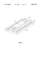
- FIG. 2 shows a two-part approach to construction of a silicon device of the present invention.
- FIG. 3 is a schematic showing the principle of thermally-induced liquid microdroplet motion in a closed channel.
- FIG. 4A shows a selected frame of a videotape wherein two microdroplets are at their starting locations in the branches of the Y-channel.
- FIG. 4B shows movement by heating the left interface of both microdroplets.
- FIG. 4C shows the microdroplets at the intersection.
- FIG. 4D shows the merging of the microdroplets to form the combined microdroplet.
- the open arrowheads in the figure indicate the rear meniscus and the filled arrowheads the leading meniscus for each microdroplet.
- FIG. 5A is a photomicrograph of inlay-process heater elements on the surface of a silicon wafer.
- FIG. 5B is a scanning electron micrograph (SEM) of an inlay-process heater wire in cross section (the arrows indicate the deposited aluminum, silicon dioxide, and silicon nitride layers).
- FIG. 5C is a SEM of a channel formed on glass using a wet-etch process, shown in cross section with the etched face of the wafer immediately adjacent to the intersection of two channels.
- FIG. 6A is a photomicrograph of polyacrylamide gel electrophoresis in a wide etched-glass channel.
- FIG. 6B is a photomicrograph of a set of four doped-diffusion diode radiation detector elements fabricated on a silicon wafer.
- FIG. 6C is an oscilloscope trace of output from the radiation detector showing individual decay events from 32 P-labeled DNA.
- FIG. 7 is a photo of gel electrophoresis of PCR reactions wherein potentially inhibiting components were added directly to the PCR.
- the present invention relates to microfabrication and biological reactions in microfabricated devices, and in particular, movement and mixing of biological samples in microdroplets through microchannels.
- the description of the invention involves I) design of microscale devices (comprising microdroplet transport channels, reaction chambers, electrophoresis ports, and radiation detectors) using silicon and glass substrates, II) movement of discrete microdroplets using a surface-tension-gradient mechanism in which discrete microdroplets are differentially heated and propelled through etched channels, and III) mixing of biological samples for reactions.
- Silicon is the material used for the construction of computing microprocessors and its fabrication technologies have developed at an unprecedented pace over the past 30 years. While this technology was initially applied to making microelectronic devices, the same techniques are currently being used for micromechanical systems.
- Continuous flow liquid transport has been described using a microfluidic device developed with silicon. See J. Pfahler et al., Sensors and Actuators, A21-A23 (1990), pp. 431-434. Pumps have also been described, using external forces to create flow, based on micromachining of silicon. See H. T. G. Van Lintel et al., Sensors and Actuators 15:153-167 (1988).
- the present invention employs discrete droplet transport in silicon (i.e., in contrast to continuous flow) using internal forces (i.e., in contrast to the use of external forces created by pumps).
- silicon As a mechanical building material, silicon has well-known fabrication characteristics.
- the economic attraction of silicon devices is that their associated micromachining technologies are, essentially, photographic reproduction techniques.
- transparent templates or masks containing opaque designs are used to photodefine objects on the surface of the silicon substrate.
- the patterns on the templates are generated with computer-aided design programs and can delineate structures with line-widths of less than one micron.
- Once a template is generated it can be used almost indefinitely to produce identical replicate structures. Consequently, even extremely complex micromachines can be reproduced in mass quantities and at low incremental unit cost--provided that all of the components are compatible with the silicon micromachining process.
- substrates such as glass or quartz
- can use photolithographic methods to construct microfabricated analysis devices only silicon gives the added advantage of allowing a large variety of electronic components to be fabricated within the same structure.
- the present invention contemplates silicon micromachined components in an integrated analysis system, including the elements identified schematically in FIG. 1.
- sample and reagent are injected into the device through entry ports (A) and they are transported as discrete droplets through channels (B) to a reaction chamber, such as a thermally controlled reactor where mixing and reactions (e.g., restriction enzyme digestion or nucleic acid amplification) occur (C).
- C mixing and reactions
- C nucleic acid amplification
- the biochemical products are then moved by the same method to an electrophoresis module (D) where migration data is collected by a detector (E) and transmitted to a recording instrument (not shown).
- D electrophoresis module
- E detector
- the fluidic and electronic components are designed to be fully compatible in function and construction with the biological reactions and reagents.
- isotropic and anisotropic etch reagents either liquid or gaseous, that can produce channels with well-defined side walls and uniform etch depths. Since the paths of the channels are defined by the photo-process mask, the complexity of channel patterns on the device is virtually unlimited. Controlled etching can also produce sample entry holes that pass completely through the substrate, resulting in entry ports on the outside surface of the device connected to channel structures.
- FIG. 2 shows a two-part approach to construction.
- Microchannels (100) are made in the silicon substrate (200) and the structure is bonded to a glass substrate (300).
- the two-part channel construction technique requires alignment and bonding processes but is amenable to a variety of substrates and channel profiles.
- the two-part approach allows for customizing one piece (i.e., the silicon with channels and reaction formats) and bonding with a standardized (non-customized) second piece, e.g., containing standard electrical pads (400).
- the present invention describes the controlled movement of liquid samples in discrete droplets in silicon.
- Discrete droplet transport involves a system using enclosed channels or tubes to transport the liquid to the desired locations (FIG. 1, B). Within the channels, discrete liquid reagent microdroplets can be injected, measured, and moved between the biochemical analysis components.
- Discrete droplet movement has three advantages. First, each sample droplet is separated from all others so that the risk of contamination is reduced. Second, in a uniform channel, the volume of each sample can be determined by merely measuring the droplet length. Third, the motion of these droplets can be accomplished with simple heating (i.e., using internal forces and no moving parts).
- Movement is performed using thermal gradients to change the interfacial tension at the front or back of the droplets and, thus, generate pressure differences across the droplet (FIG. 3).
- a droplet in a hydrophilic channel can be propelled forward by heating the back interface.
- the local increase in temperature reduces the surface tension on the back surface of the droplet and, therefore, decreases the interfacial pressure difference.
- the decreased pressure difference corresponds to an increase in the local internal pressure on that end of the droplet (P 1 increases).
- P 1 increases.
- the two droplet interfaces are no longer in equilibrium, with P 1 greater than P 2 , and the pressure difference propels the droplet forward.
- forward motion can be maintained by continuing to heat the droplet at the rear surface with successive heaters along the channel, while heating the front surface can be used to reverse the motion of the droplet.
- Applying a voltage to the wire beneath the channel generates heat under the edge of the droplet. Heating the left interface increases the internal pressure on that end of the droplet and forces the entire droplet to the right.
- the pressure on the interior of the droplet can be calculated knowing the atmospheric pressure, P atmP the surface tension, ⁇ , and the dimensions of the channel.
- P i P atm -(4 ⁇ cos ⁇ )/d where d is the diameter of the channel and ⁇ is the contact angle.
- ⁇ o and b are positive constants and T is the temperature
- increasing the temperature on the left end of the droplet decreases the surface tension and, therefore, increases the internal pressure on that end.
- the pressure difference between the two ends then pushes the droplet towards the direction of lower pressure (i.e., towards the right).
- the aqueous droplet shown is in a hydrophilic channel (0 ⁇ 90); for a hydrophobic channel (90 ⁇ 180), heating the right edge would make the droplet move to the right.
- Contact angle hysteresis (the contact angle on the advancing edge of the droplet is larger than the contact angle on the retreating edge) requires a minimum temperature difference before movement will occur.
- the present invention contemplates temperature differences of greater than thirty (30) degrees Centigrade to create movement. Experiments using temperature sensors arrayed along the entire channel indicate that a differential of approximately 40° C. across the droplet is sufficient to provide motion. In these experiments, the channel cross-section was 20 ⁇ m ⁇ 500 ⁇ m, and the volume of each of these droplets can be calculated from their lengths and is approximately 100 nanoliters for a 1 cm long droplet.
- Droplet motion (described generally above) is contemplated as one step in a pathway.
- the other steps typically involve sample mixing and a controlled reaction.
- the integral heaters arrayed along the entire surface of the channel used for droplet motion also allow for a region of a channel to be used as a thermal reaction chamber.
- a Y-channel device is contemplated (FIG. 4A).
- a first droplet containing a first sample e.g., nucleic acid
- a second droplet containing a second sample e.g., a restriction digest enzyme in digestion buffer
- the characteristic time for this mixing could be on the order of several hours or more. Circulation patterns generated inside the droplets during movement and heating significantly reduce this time.
- the present invention contemplates maintaining the mixture as a heated mixture (e.g., maintaining the temperature at 65° C. for 10 minutes) using the integral heaters and temperature sensors.
- the present invention contemplates mixing by reversing the flow direction of the mixture over a relatively short distance in the channel. While a variety of reverse flow approaches are possible, one or two direction changes over a distance comprising approximately two droplet lengths has been found to be adequate.
- the mixture is moved against or over physical obstacles.
- the mixture can be either “crashed” back against merge point of the Y-channel or simply moved over deliberate imperfections in the channel (i.e., "roller coaster” mixing).
- Successful mixing can be confirmed by characterization of the product(s) from the reaction. Where product is detected, mixing has been at least partially successful.
- the present invention contemplates, in one embodiment, using electrophoresis to confirm product formation.
- the description of the preferred embodiments involves: I) microfabrication techniques for manufacture of silicon-based devices; II) channel treatment for optimum flow and reproducibility; and III) component design (particularly the electrophoresis module and the radiation detectors).
- planar process relies on the unique characteristics of silicon and comprises a complex sequence of manufacturing steps involving deposition, oxidation, photolithography, diffusion and/or ion implantation, and metallization, to fabricate a "layered" integrated circuit device in a silicon substrate. See e.g., W. Miller, U.S. Pat. No. 5,091,328, hereby incorporated by reference.
- oxidation of a crystalline silicon substrate results in the formation of a layer of silicon dioxide on the substrate surface.
- Photolithography can then be used to selectively pattern and etch the silicon dioxide layer to expose a portion of the underlying substrate.
- These openings in the silicon dioxide layer allow for the introduction (“doping") of ions (“dopant”) into defined areas of the underlying silicon.
- the silicon dioxide acts as a mask; that is, doping only occurs where there are openings. Careful control of the doping process and of the type of dopant allows for the creation of localized areas of different electrical resistivity in the silicon.
- acceptor ion-doped (positive free hole, "p") regions and donor ion-doped (negative free electron, "n") regions in large part defines the interrelated design of the transistors, resistors, capacitors and other circuit elements on the silicon wafer. Electrical interconnection and contact to the various p or n regions that make up the integrated circuit is made by a deposition of a thin film of conductive material, usually aluminum or polysilicon, thereby finalizing the design of the integrated circuit.
- channels were prepared on 500 ⁇ m thick glass wafers (Dow Corning 7740) using standard aqueous-based etch procedures.
- the initial glass surface was cleaned and received two layers of electron beam evaporated metal (20 nm chromium followed by 50 nm gold).
- Photoresist Microposit 1813 (Shipley Co.) was applied 4000 rpm, 30 seconds; patterned using glass mask 1 and developed.
- the metal layers were etched in chromium etchant (Cr-14, Cyantek Inc.) and gold etchant (Gold Etchant TFA, Transene Co.) until the pattern was clearly visible on the glass surface.
- the accessible glass was then etched in a solution of hydrofluoric acid and water (1:1, v/v).
- Etch rates were estimated using test wafers, with the final etch typically giving channel depths of 20 to 30 ⁇ m. For each wafer, the depth of the finished channel was determined using a surface profilometer. The final stripping (PRS-2000, J.T. Baker) removed both the remaining photoresist material and the overlying metal.
- channels etched on glass in the above-described manner were bonded to the heater-element wafer in a two-part construction approach using optical adhesive (SK-9 Lens Bond, Sumers Laboratories, Fort Washington, Pa.). The bond was cured under an ultraviolet light source (365 nm) for 12 to 24 hours.
- optical adhesive SK-9 Lens Bond, Sumers Laboratories, Fort Washington, Pa.
- Initial device design by the present inventors involved single layers of silicon. However, experience showed these to be inadequate to prevent short circuiting due to (necessary) liquid microdroplets within the channels (see experiments described below).
- the preferred design involves a triple layer of oxides. Such a preferred device capable of moving and mixing nanoliter droplets was constructed by bonding a planar silicon substrate to channels etched in a glass cover. A series of metal heaters was inlaid on the silicon substrate as two parallel lanes merging into a single lane (a "Y"-shape) (FIG. 5A).
- the heating elements were formed by first coating the wafer with a 1.0 ⁇ m layer of thermal silicon dioxide Next, 0.35 ⁇ m deep, 5 ⁇ m wide grooves were reactive-ion etched (RIE) into the silicon dioxide following the pattern set in an overlying photoresist. Aluminum was deposited (0.35 ⁇ m) across the entire wafer using electron beam evaporation and the metal layer was "lifted-off" from all surfaces having intact photoresist using a stripping solution. The metal inlay process gives a relatively planar surface and provides a uniform base for deposition of a solution-impermeable barrier layer.
- RIE reactive-ion etched
- the barrier layer is made by a sequence of three plasma-enhanced chemical vapor depositions (PECVD): 1.0 ⁇ m silicon oxide (SiO x ), 0.25 ⁇ m silicon nitride (Si x N y ), and 1.0 ⁇ m silicon oxide (SiO x ) (FIG. 5B). Some heating elements were also used as resistive temperature sensors.
- PECVD plasma-enhanced chemical vapor depositions
- Heater elements were fabricated as follows. Silicon wafer (p-type, 18-221/2-cm, ⁇ 100>, boron concentration ⁇ 10 15 cm -3 ) was used as a substrate for growth of SiO 2 thermal oxide (1 ⁇ m); photoresist (AZ-5214-E, Hoescht-Celanese) was applied and spun at 3000 rpm, 30 seconds. The resist was patterned (metal 1) and developed.
- Reactive ion etch (RIE, PlasmaTherm, Inc.) was performed to 0.35 ⁇ m depth into the SiO 2 layer at the following conditions: CHF 3 , 15 sccm (standard cubic centimeters per minute); CF 4 , 15 sccm; 4 mTorr; DC bias voltage of 200V, 100 W, 20 minutes.
- the etch depth was measured by profilometer and 0.35 ⁇ m metallic aluminum was electron beam deposited.
- the resist and overlying metal was lifted off by development using Microposit 1112A remover in solution (Shipley Co.).
- the barrier layers consist of sequentially deposited 1 ⁇ m SiO x , 0.25 ⁇ m Si x N y , and 1 ⁇ m SiO x using plasma-enhanced chemical vapor deposition (PECVD).
- PECVD plasma-enhanced chemical vapor deposition
- RIE was used to etch contact holes to the metal layer using a second mask (CHF 3 , 15 sccm; CF 4 , 15 sccm; 4 mTorr; and DC bias voltage of 200V, 100 W, 120 minutes).
- the elements are arrayed as two parallel lanes, each 500 ⁇ m wide, merging into one lane.
- the individual heaters consist of paired aluminum wires (5 ⁇ m) winding across the 500 ⁇ m wide region.
- the broad metal areas on either side of the elements are bonding locations for connection to external circuitry.
- the width of the aluminum element is 5 ⁇ m.
- the channel in FIG. 5C has identical width and design configurations as the heating element lanes in FIG. 5A, and is uniformly etched 500 ⁇ m wide and approximately 20 ⁇ m deep.
- the heating-element wafer was bonded to a glass wafer containing etched channels with the same "Y" format.
- An aqueous chemical etch of concentrated hydrofluoric acid was used to produce channels with defined side walls and uniform depth.
- the etched channels are defined by a chromium/gold mask and are 500 ⁇ m wide and approximately 20 ⁇ m deep (FIG. 3C).
- the complementary silicon heater and glass channel wafers were aligned and then bonded with adhesive to form the finished device.
- Each heating element used as a temperature sensor is preferably first calibrated by measurement of electrical resistance at 22° C. and 65° C. under constant voltage; intermediate temperatures are estimated by linear interpolation.
- the channels Prior to performing microdroplet motion and biological reactions, the channels are preferably treated by washing with base, acid, buffer, water and a hydrophilicity-enhancing compound, followed by a relatively high concentration solution of nonspecific protein.
- the channels are washed with approximately 100 ⁇ l each of the following solutions in series: 0.1N NaOH; 0.1N HCl; 10 mM Tris-HCl (pH 8.0), deionized H 2 O, Rain-X Anti-Fog (a hydrophilicity-enhancing compound commercially available from Unelko Corp., Scottsdale, Ariz.), and 500 ⁇ g/ ⁇ l bovine serum albumin (non-specific protein commercially available in restriction enzyme grade from GIBCO-BRL).
- the wafer was placed on a stereoscope stage (Olympus SZ1145), and the contact pads for the heating elements were connected to a regulated power supply. Heating occurred by passing approximately 30 volts through the element in short pulses and observing the movement rate of the droplets. A detectable reduction in droplet volume from evaporation was noted in each experiment, usually of less than 30%. Droplet movement was recorded with a Hamamatsu video camera on videotape.
- the present invention contemplates one or more gel electrophoresis modules as a component of the microscale device.
- Theoretical and empirical research has indicated that reducing the thickness of the electrophoresis channel leads to improved resolution. Thinner gels dissipate heat more readily and allow higher voltages to be used, with concomitant improvements in separation.
- the position and width of the electrophoresis detector are also critical to the ultimate resolution of the electrophoresis system.
- a micromachined electronic detector, such as a photodiode, placed in the underlying silicon substrate can be less than one micron from the gel matrix and can have a width of 5 microns or less. Since the gel length required for the resolution of two migrating bands is proportional to the resolution of the detector, the incorporation of micron-width electronic detectors can reduce the total gel length required for standard genotyping by at least an order of magnitude.
- modules were fabricated using etched glass channels identical to FIG. 4B and fluorescent-labeled DNA (YOYO intercalating dye).
- Polyacrylamide gel electrophoresis of a complex DNA mixture is shown in FIG. 6A in a channel 500 ⁇ m wide and 20 ⁇ m deep. The electrophoresis was performed with the positive electrode to the right and the DNA sample applied at the left. The white vertical line is the gel-to-buffer interface.
- the DNA sample (BluescriptKS digested with MspI) is labeled with intercalating UV-fluorescent dye (YOYO-1) and is visualized under incandescent light. Separation of the component bands is clearly visible less than 300 ⁇ m from the buffer reservoir-to-gel interface.
- the high resolution of the detector in this case, a microscope allowed the use of an unusually short gel, resolving several closely eluting bands.
- the present invention contemplates an electrophoresis unit that integrates a micromachined channel and an electronic DNA detector.
- the channel is constructed using a sacrificial etch process on a single silicon wafer rather than the bonded surface-etch method described earlier.
- the channel configuration is patterned by depositing on the wafer surface an etch-sensitive material (phosphosilicate glass, SiO 2 .P x ) with a thickness equivalent to the desired channel height.
- a triple-layer overlay of plasma-enhanced chemical vapor deposited silicon nitride, undoped polycrystalline silicon, and silicon nitride (Si x N y /polySi/Si x N y ) completely covers the sacrificial material with the exception of small access holes on the top or sides.
- a selective liquid etch removes the sacrificial layer material, but not the overlay or the underlying substrate.
- the sacrificial etch technique results in a complete channel being formed directly on the substrate containing the electronic components (FIGS. 4C and 4D).
- the 3 ⁇ m deep channel has two buffer reservoirs on either end with integral phosphorus-doped polycrystalline silicon electrodes.
- the channel height formed by this technique ( ⁇ 3 ⁇ m) is considerably smaller than the height of the bonded structures due to the limitations of the sacrificial layer deposition and the strength of the overlying layer. Note that, for these channel dimensions, liquid drops would have volumes on the order of picoliters.
- FIG. 6B is photomicrograph of a set of four doped-diffusion diode radiation detector elements fabricated on a silicon wafer. For each element, the three parallel dark lines define the diffusion regions of the central the detector flanked by the guard ring shielding electrodes. The diffusion regions are approximately 300 ⁇ m long and 4 ⁇ m wide.
- a radiation detector consisting of a 10 ⁇ m wide "p-n"-type diode with a 5 ⁇ m wide guard ring around the outer edge, is fashioned directly into the silicon substrate underneath the channel.
- an integral radiation detector was chosen because of (i) high sensitivity (a single decay event), (ii) small aperture dimensions, and (iii) well-know fabrication and response characteristics.
- a 1 cm long, 3 ⁇ m thick gel is able to perform as separation on a 80 and a 300 base-pair fragment of DNA.
- this diode although currently configured for high-energy beta particle detection, can also operate as a photon detector. With proper wavelength filters and light sources, detection of fluorescence emission may be accommodated with a similar device.
- Radiation detectors were prepared as follows. A 2001/2-cm, ⁇ 100>, float zone, boron-doped, p-type silicon wafer was used as a substrate. Diffused layers of phosphorus (5 ⁇ 10 14 cm -2 ) and boron (1 ⁇ 10 15 cm -2 ) were ion-implanted onto the sample in lithographically-defined regions; thermal silicon oxide was grown (0.2 ⁇ m at 900° C.) over the wafer; and contact holes were etched to the diffusion layer using buffered hydrofluoric acid solution (5:1).
- a 3.3 ⁇ m layer of Microposit 1400-37 photoresist was patterned to define the metal pads; 50 nm chromium followed by 400 nm gold was evaporated over the resist; and the metallization lifted off the regions retaining the resist.
- a layer of Microposit 1813 photoresist was applied across the wafer and baked for 110° C. for 30 minutes to form an aqueous solution barrier. Radioactive phosphorus ( 32 P) decay events could be detected using a sample of labeled DNA in PCR reaction buffer placed on the photoresist layer.
- the detector was connected to a charge-sensitive preamplifier (EV-Products 550A), followed by a linear shaping amplifier and a standard oscilloscope.
- FIG. 6C shows an oscilloscope trace of output from the radiation detector showing individual decay events from 32 P-labeled DNA.
- the aqueous DNA sample was placed directly on the detector and sampled for 30 seconds.
- the screen is displaying a vertical scale of 0.5V/division and horizontal scale of 20 ⁇ sec/division.
- This example describes approaches to the problem of forming a moisture barrier over electrical elements of the microscale device.
- Initial prototypes employed 5000 angstroms of aluminum and covered it with PECVD SiO x . Upon testing, it was determined that the liquids were penetrating this later and destroying the aluminum heating elements.
- This example describes approaches to enhancing droplet motion by surface treatment.
- the principle of using surface tension to cause droplets to move may be applied to either hydrophilic or hydrophobic surfaces.
- Glass for instance, is naturally hydrophilic with a near zero contact angle with water. Because the oxide coating of the present invention is made principally of the same material as glass, it was expected that the devices would also exhibit near zero angles. It was discovered, however, that the actual construction materials had contact angles far from zero, thus enhancing the effects of contact angle hysteresis (discussed in greater detail in Example 3). For instance, water gave a contact angle (static) of ⁇ 42° on polyamide, ⁇ 41° on SiO 2 (major component of most glasses), ⁇ 62° on silicone spray. To enhance the surface effectiveness, several treatment processes for both hydrophilic and hydrophobic surfaces were tried, as described below.
- Rain-X antifog (commercially available) as a treatment was observed to work. This is a surface treatment which makes surfaces hydrophilic. Although, the resulting surfaces may not be 0°, by using this coating the entire surface gets treated giving a uniform surface for the droplet. Experimentally, it was found that Rain-X antifog treatments greatly enhanced droplet motion experiments using heat. Another such treatment which was tested but which did not work was a material called SilWet. This material is used in the agriculture industry for enhancing the wetting of plants with agricultural sprays.
- This example describes approaches to droplet motion by heat treatment.
- the contact angle on the advancing end of a liquid droplet in motion (known as the advancing contact angle) is greater that the that on the receding end (receding contact angle).
- the hydrophilic surface--such as water on glass-- this tends to create a back pressure countering attempts at forward motion by heating the back side of a droplet. This is best shown by a simple model describing laminar flow through a channel.
- ⁇ G change in surface tension between the ends of the droplet.
- ⁇ v> [0.16*R/(8 ⁇ L)]*(T back -T front ).
- CAH contact angle hysteresis
- the advancing angle is 36° and the receding angle is 29° (with the front of the droplet being 25° C.)
- the back of the droplet would need to be heated to ⁇ 60° C. for a 1 mm long droplet in a 20 ⁇ m high channel. This is just one example situation.
- the device consists of a series of aluminum heaters inlaid on a planar silicon dioxide substrate (similar to the structure shown in FIG. 2) and bonded by glue to a wet-etched glass channel (20 ⁇ m depth, 500 ⁇ m width). Liquid samples were manually loaded into the two channels on the left using a micropipette. Heating the left interface of each droplet propels it toward the intersection of the channels. At the intersection, the droplets meet and join to form a single larger droplet. Note that, since the channel cross-section is 20 ⁇ m ⁇ 500 ⁇ m, the volume of each of these droplets can be calculated from their lengths and is approximately 50 nanoliters.
- the heaters along the entire surface of the channel shown in FIG. 4 allow it to be used as a thermal reaction chamber in addition to a droplet-motion device.
- the upper droplet in the figure contains a DNA sample, while the lower contains a restriction digest enzyme (TaqI) and digestion buffer. Following sample merging, the combined droplet was maintained at 65° C. for 30 minutes using the integral heaters and temperature sensors.
- the completed enzymatic reaction was confirmed by expressing the droplet from the right end of the channel and loading it onto a capillary gel electrophoresis system with a laser-induced fluorescence detector.
- the chromatogram produced by the silicon-device sample was similar to chromatograms generated from DNA digests runs in a standard polypropylene microreaction vessel (not shown).
- a preferred glue was a UV cured glue, although the process of applying the UV glue is tedious and requires some practice to avoid putting the glue in places where it does not belong, e.g., in the channels.
- This example describes a nucleic acid amplification reaction on a silicon-based substrate.
- the established DNA biochemistry steps for PCR occur within physiological conditions of ionic strength, temperature, and pH.
- the reaction chamber components have design limitations in that there must be compatibility with the DNA, enzymes and other reagents in solution.
- the present inventors began by coating a standard silicon wafer with a 0.5 ⁇ m layer of silicon dioxide. Next, a 0.3 ⁇ m deep, 500 ⁇ m wide channel was etched into the silicon oxide and gold or aluminum was deposited (0.3 ⁇ m thick). This inlay process results in a relatively planar surface (FIG. 2A) and provides a base for deposition of a water-impermeable layer.
- the impermeable layer is made by a sequence of three plasma enhanced vapor depositions: silicon oxide (SiO x ), silicon nitride (Si x N y ), and silicon oxide (SiO x ).
- a device fabricated with metal resistive heaters and oxide/nitride/oxide coating was tested for biological compatibility and temperature control by using PCR amplification of a known DNA template sample.
- the reaction was carried out on the planar device using twenty microliters of PCR reaction mix covered with mineral oil to prevent evaporation.
- the reaction mixture was cycled through a standard 35-cycle PCR temperature cycling regime using the integral temperature sensors linked to a programmable controller. Since the reaction volume was significantly larger than intended for the original heater design, a polypropylene ring was cemented to the heater surface to serve as a sample containment chamber. In all test cases, the presence of amplified reaction products indicated that the silicon dioxide surface and the heater design did not inhibit the reaction.
- Parallel amplification experiments performed on a commercial PCR thermocycler gave similar results.
- a series of PCR compatibility tests indicated that the reaction on the device is very sensitive to controller settings and to the final surface material in contact with the sample (not shown).
- the present invention can be adapted for high-volume projects, such as genotyping.
- the microdroplet transport avoids the current inefficiencies in liquid handling and mixing of reagents.
- the devices are not limited by the nature of the reactions, including biological reactions.
Abstract
Description
<v>=-ΔP*[R.sup.2 /(8 μL]
<v>=-(ΔG)*(1/R)*[R.sup.2 /(8 μL)]=[-0.16*ΔT*R/(8 μL)]
G.sub.front /G.sub.back >(R.sub.front /R.sub.back)*(cos β.sub.back /cos β.sub.front)
______________________________________
Adhesive  Form    Dries   Texture
                                 Comments
______________________________________
 1. Dymax UV  Gel     Clear Rubbery
                                   Cures on UV
   Glue    exposure.
   2. Carter's Goo Yellow/ Rubbery Dries quickly and
   Rubber  Clear  stringy when thinned.
   Cement
   3. Borden's Liquid Clear Hard Thin, dries on first
   Krazy Glue    contact.
   4. UHU Bond- Gel/ Clear Hard Dries quickly and
   All Goo   stringy when thin.
   5. Dennison Paste Clear Hard Will not flow on
   Permanent    applying.
   Glue Stick
   6. Elmer's Thick White Hard Slow drying.
   Glue-All Liquid
   (Borden)
   7. Liquid Nails Thin Wood- Hard Thick, dries quickly
    Paste like  when thinned.
   8. Devcon 5- Gel Yellow/ Hard Thick, cures on about
   Minute  Clear  5 min.
   Epoxy
   9. Scotch Tape Clear Rubbery Tape.
   Double-Stick
   Tape
  10. Dow Corn- Thick Frosty Soft Seals but does not
   ing High Gel   bond.
   Vacuum
   Grease
  11. Nujol Miner- Liquid Clear Runny Neither seals (doesn't
   al Oil     spread on glass) nor
   (Perkin    bonds.
   Elmer)
  12. Household Gel/ Clear Rubbery Contact cement which
   Goop Goo   dries stringy.
  13. Permatex Gel/ Yellow/ Rubbery Dries quickly and
   Weather Goo Clear  stringy when thinned.
   Strip Cement
  14. Thick Gel Gel Clear Hard Does not cure on
   Super Glue    contact but does
       quickly.
  15. DAP Weld- Goo Orange/ Rubbery Contact cement which
   wood Con-  Clear  gets stringy when
   tact Cement    thinned.
  16. Scotch (3M) Thin Yellow/ Rubbery Spray. `Gooey` but
   Photo Mount Goo Clear  not stringy.
   Spray
   Adhesive
  17. Silicone Liquid Clear Smooth Spray. Dries to thin,
   Resin (spray)    clear, and sealed
   Lacquer (GC    coating.
   Electronics)
______________________________________
Claims (12)
Priority Applications (10)
| Application Number | Priority Date | Filing Date | Title |
|---|---|---|---|
| US08/529,293 US6057149A (en) | 1995-09-15 | 1995-09-15 | Microscale devices and reactions in microscale devices |
| US08/888,309 US6048734A (en) | 1995-09-15 | 1997-07-03 | Thermal microvalves in a fluid flow method |
| US08/938,689 US6130098A (en) | 1995-09-15 | 1997-09-26 | Moving microdroplets |
| US09/271,963 US6271021B1 (en) | 1995-09-15 | 1999-03-18 | Microscale devices and reactions in microscale devices |
| US09/517,680 US6949385B1 (en) | 1995-09-15 | 2000-03-02 | Thermal microvalves |
| US09/518,895 US6911183B1 (en) | 1995-09-15 | 2000-03-06 | Moving microdroplets |
| US09/751,493 US7066453B2 (en) | 1995-09-15 | 2000-12-28 | Microscale reaction devices |
| US11/119,539 US8071056B2 (en) | 1995-09-15 | 2005-04-29 | Thermal microvalves |
| US11/168,144 US20070042503A1 (en) | 1995-09-15 | 2005-06-28 | Moving microdroplets |
| US13/311,087 US8617905B2 (en) | 1995-09-15 | 2011-12-05 | Thermal microvalves |
Applications Claiming Priority (1)
| Application Number | Priority Date | Filing Date | Title |
|---|---|---|---|
| US08/529,293 US6057149A (en) | 1995-09-15 | 1995-09-15 | Microscale devices and reactions in microscale devices |
Related Child Applications (3)
| Application Number | Title | Priority Date | Filing Date |
|---|---|---|---|
| US08/888,309 Continuation-In-Part US6048734A (en) | 1995-09-15 | 1997-07-03 | Thermal microvalves in a fluid flow method |
| US09/271,963 Continuation US6271021B1 (en) | 1995-09-15 | 1999-03-18 | Microscale devices and reactions in microscale devices |
| US09/271,963 Division US6271021B1 (en) | 1995-09-15 | 1999-03-18 | Microscale devices and reactions in microscale devices |
Publications (1)
| Publication Number | Publication Date |
|---|---|
| US6057149A true US6057149A (en) | 2000-05-02 |
Family
ID=24109298
Family Applications (3)
| Application Number | Title | Priority Date | Filing Date |
|---|---|---|---|
| US08/529,293 Expired - Lifetime US6057149A (en) | 1995-09-15 | 1995-09-15 | Microscale devices and reactions in microscale devices |
| US09/271,963 Expired - Lifetime US6271021B1 (en) | 1995-09-15 | 1999-03-18 | Microscale devices and reactions in microscale devices |
| US09/751,493 Expired - Fee Related US7066453B2 (en) | 1995-09-15 | 2000-12-28 | Microscale reaction devices |
Family Applications After (2)
| Application Number | Title | Priority Date | Filing Date |
|---|---|---|---|
| US09/271,963 Expired - Lifetime US6271021B1 (en) | 1995-09-15 | 1999-03-18 | Microscale devices and reactions in microscale devices |
| US09/751,493 Expired - Fee Related US7066453B2 (en) | 1995-09-15 | 2000-12-28 | Microscale reaction devices |
Country Status (1)
| Country | Link |
|---|---|
| US (3) | US6057149A (en) |
Cited By (154)
| Publication number | Priority date | Publication date | Assignee | Title |
|---|---|---|---|---|
| WO2001000863A1 (en) * | 1999-06-25 | 2001-01-04 | Integrated Genetic Devices Ltd. | Apparatus, system and method for automated execution and analysis of biological and chemical reactions |
| US20010046701A1 (en) * | 2000-05-24 | 2001-11-29 | Schulte Thomas H. | Nucleic acid amplification and detection using microfluidic diffusion based structures |
| US6337740B1 (en) | 1996-07-16 | 2002-01-08 | Caliper Technologies Corp. | Microfluidic devices for electrophoretic analysis of materials |
| US6444474B1 (en) * | 1998-04-22 | 2002-09-03 | Eltron Research, Inc. | Microfluidic system for measurement of total organic carbon |
| US20020142471A1 (en) * | 2001-03-28 | 2002-10-03 | Kalyan Handique | Methods and systems for moving fluid in a microfluidic device |
| US20020143437A1 (en) * | 2001-03-28 | 2002-10-03 | Kalyan Handique | Methods and systems for control of microfluidic devices |
| US20020142482A1 (en) * | 2001-03-28 | 2002-10-03 | Betty Wu | Methods and systems for releasing intracellular material from cells within microfluidic samples of fluids |
| US20020195343A1 (en) * | 2001-06-20 | 2002-12-26 | Coventor, Inc. | Microfabricated separation device employing a virtual wall for interfacing fluids |
| US20020197733A1 (en) * | 2001-06-20 | 2002-12-26 | Coventor, Inc. | Microfluidic system including a virtual wall fluid interface port for interfacing fluids with the microfluidic system |
| US20030007898A1 (en) * | 2001-06-20 | 2003-01-09 | Coventor, Inc. | Microfluidic system including a virtual wall fluid interface port for interfacing fluids with the microfluidic system |
| US20030049174A1 (en) * | 2001-09-12 | 2003-03-13 | Karthik Ganesan | Microfluidic devices having a reduced number of input and output connections |
| US20030057199A1 (en) * | 2001-04-23 | 2003-03-27 | Stmicroelectronics S.R.L. | Integrated device based upon semiconductor technology, in particular chemical microreactor |
| US6544734B1 (en) | 1998-10-09 | 2003-04-08 | Cynthia G. Briscoe | Multilayered microfluidic DNA analysis system and method |
| US20030077570A1 (en) * | 2001-09-20 | 2003-04-24 | Coventor, Inc. | Small molecule substrate based enzyme activity assays |
| US6575188B2 (en) | 2001-07-26 | 2003-06-10 | Handylab, Inc. | Methods and systems for fluid control in microfluidic devices |
| WO2003050854A2 (en) * | 2001-12-12 | 2003-06-19 | The Pennsylvania State University | Chemical reactor templates: sacrificial layer fabrication and template use |
| US20030157783A1 (en) * | 2002-01-11 | 2003-08-21 | The Penn State Research Foundation | Use of sacrificial layers in the manufacture of high performance systems on tailored substrates |
| US20030213693A1 (en) * | 2002-01-18 | 2003-11-20 | The Regents Of The University Of Michigan | Microscale electrophoresis devices for biomolecule separation and detection |
| US20030230486A1 (en) * | 2002-03-05 | 2003-12-18 | Caliper Technologies Corp. | Mixed mode microfluidic systems |
| US6710311B2 (en) * | 2000-06-05 | 2004-03-23 | Stmicroelectronics S.R.L. | Process for manufacturing integrated chemical microreactors of semiconductor material |
| US20040058450A1 (en) * | 2002-09-24 | 2004-03-25 | Pamula Vamsee K. | Methods and apparatus for manipulating droplets by electrowetting-based techniques |
| US20040055536A1 (en) * | 2002-09-24 | 2004-03-25 | Pramod Kolar | Method and apparatus for non-contact electrostatic actuation of droplets |
| US20040055891A1 (en) * | 2002-09-24 | 2004-03-25 | Pamula Vamsee K. | Methods and apparatus for manipulating droplets by electrowetting-based techniques |
| US20040115830A1 (en) * | 2002-09-25 | 2004-06-17 | Igor Touzov | Components for nano-scale Reactor |
| US6756018B2 (en) * | 2001-02-12 | 2004-06-29 | Agilent Technologies, Inc. | Method and apparatus for selective execution of microfluidic circuits utilizing electrically addressable gas generators |
| US20040219070A1 (en) * | 2001-02-14 | 2004-11-04 | Handylab, Inc., A Delaware Corporation | Heat-reduction methods and systems related to microfluidic devices |
| US6825127B2 (en) | 2001-07-24 | 2004-11-30 | Zarlink Semiconductor Inc. | Micro-fluidic devices |
| US20050039452A1 (en) * | 2003-08-20 | 2005-02-24 | Lockheed Martin Corporation | Solid state thermal engine |
| US20050074782A1 (en) * | 2003-10-03 | 2005-04-07 | The Regents Of The University Of Michigan | Methods of performing biochemical reactions in a convective flow field |
| US20050244481A1 (en) * | 2004-04-30 | 2005-11-03 | Kimberly-Clark Worldwide, Inc. | Personal care products and methods for inhibiting the adherence of flora to skin |
| US6977163B1 (en) * | 2001-06-13 | 2005-12-20 | Caliper Life Sciences, Inc. | Methods and systems for performing multiple reactions by interfacial mixing |
| US7066453B2 (en) * | 1995-09-15 | 2006-06-27 | The Regents Of The University Of Michigan | Microscale reaction devices |
| US20060194331A1 (en) * | 2002-09-24 | 2006-08-31 | Duke University | Apparatuses and methods for manipulating droplets on a printed circuit board |
| US20070292941A1 (en) * | 2006-03-24 | 2007-12-20 | Handylab, Inc. | Integrated system for processing microfluidic samples, and method of using the same |
| US20070295372A1 (en) * | 2006-06-22 | 2007-12-27 | Institute For Research & Industry Cooperation, Pusan National University | Device for passive microfluidic washing using capillary force |
| US20080182301A1 (en) * | 2006-03-24 | 2008-07-31 | Kalyan Handique | Microfluidic system for amplifying and detecting polynucleotides in parallel |
| US20080207892A1 (en) * | 2006-11-22 | 2008-08-28 | Yoshihide Iwaki | Nucleic acid amplification method using microchip and microchip, and nucleic acid amplification system using the same |
| EP1970346A2 (en) | 2007-03-15 | 2008-09-17 | DALSA Semiconductor Inc. | Microchannels for biomens devices |
| US7427526B2 (en) | 1999-12-20 | 2008-09-23 | The Penn State Research Foundation | Deposited thin films and their use in separation and sacrificial layer applications |
| US20090019924A1 (en) * | 2005-03-18 | 2009-01-22 | Nanyang Technological University | Microfluidic Sensor for Interfacial Tension Measurement and Method for Measuring Interfacial Tension |
| US20090042319A1 (en) * | 2005-06-16 | 2009-02-12 | Peter Patrick De Guzman | Biosensor Detection By Means Of Droplet Driving, Agitation, and Evaporation |
| US20090072332A1 (en) * | 2006-03-20 | 2009-03-19 | Koniklijke Phillips Electronics N.V | System-in-package platform for electronic-microfluidic devices |
| US20090071833A1 (en) * | 2004-02-20 | 2009-03-19 | Vera Gorfinkel | Method and device for manipulating liquids in microfluidic systems |
| US20090113378A1 (en) * | 2007-10-30 | 2009-04-30 | International Business Machines Corporation | Extending unified process and method content to include dynamic and collaborative content |
| US20090134069A1 (en) * | 2007-07-13 | 2009-05-28 | Handylab, Inc. | Integrated Heater and Magnetic Separator |
| US20100064780A1 (en) * | 2005-07-27 | 2010-03-18 | Howard A Stone | Pressure Determination In Microfludic Systems |
| US20100126860A1 (en) * | 2007-08-09 | 2010-05-27 | Advanced Liquid Logic, Inc. | PCB Droplet Actuator Fabrication |
| US7731906B2 (en) | 2003-07-31 | 2010-06-08 | Handylab, Inc. | Processing particle-containing samples |
| US20100155907A1 (en) * | 2008-12-23 | 2010-06-24 | Soendker Erich H | Semiconductor device having an inorganic coating layer applied over a junction termination extension |
| EP2204348A2 (en) | 2009-01-05 | 2010-07-07 | DALSA Semiconductor Inc. | Method of making bio MEMS devices |
| USRE41780E1 (en) | 2003-03-14 | 2010-09-28 | Lawrence Livermore National Security, Llc | Chemical amplification based on fluid partitioning in an immiscible liquid |
| US7829025B2 (en) | 2001-03-28 | 2010-11-09 | Venture Lending & Leasing Iv, Inc. | Systems and methods for thermal actuation of microfluidic devices |
| US20110053798A1 (en) * | 2009-09-02 | 2011-03-03 | Quantalife, Inc. | System for mixing fluids by coalescence of multiple emulsions |
| US20110086780A1 (en) * | 2008-09-23 | 2011-04-14 | Quantalife, Inc. | System for forming an array of emulsions |
| US20110212516A1 (en) * | 2008-09-23 | 2011-09-01 | Ness Kevin D | Flow-based thermocycling system with thermoelectric cooler |
| US20110217712A1 (en) * | 2010-03-02 | 2011-09-08 | Quantalife, Inc. | Emulsion chemistry for encapsulated droplets |
| US8088616B2 (en) | 2006-03-24 | 2012-01-03 | Handylab, Inc. | Heater unit for microfluidic diagnostic system |
| US8105783B2 (en) | 2007-07-13 | 2012-01-31 | Handylab, Inc. | Microfluidic cartridge |
| US8133671B2 (en) | 2007-07-13 | 2012-03-13 | Handylab, Inc. | Integrated apparatus for performing nucleic acid extraction and diagnostic testing on multiple biological samples |
| US8182763B2 (en) | 2007-07-13 | 2012-05-22 | Handylab, Inc. | Rack for sample tubes and reagent holders |
| US8216530B2 (en) | 2007-07-13 | 2012-07-10 | Handylab, Inc. | Reagent tube |
| USD665095S1 (en) | 2008-07-11 | 2012-08-07 | Handylab, Inc. | Reagent holder |
| US8287820B2 (en) | 2007-07-13 | 2012-10-16 | Handylab, Inc. | Automated pipetting apparatus having a combined liquid pump and pipette head system |
| USD669191S1 (en) | 2008-07-14 | 2012-10-16 | Handylab, Inc. | Microfluidic cartridge |
| US8324372B2 (en) | 2007-07-13 | 2012-12-04 | Handylab, Inc. | Polynucleotide capture materials, and methods of using same |
| US8470586B2 (en) | 2004-05-03 | 2013-06-25 | Handylab, Inc. | Processing polynucleotide-containing samples |
| USD692162S1 (en) | 2011-09-30 | 2013-10-22 | Becton, Dickinson And Company | Single piece reagent holder |
| US8617905B2 (en) | 1995-09-15 | 2013-12-31 | The Regents Of The University Of Michigan | Thermal microvalves |
| US8663920B2 (en) | 2011-07-29 | 2014-03-04 | Bio-Rad Laboratories, Inc. | Library characterization by digital assay |
| US8709762B2 (en) | 2010-03-02 | 2014-04-29 | Bio-Rad Laboratories, Inc. | System for hot-start amplification via a multiple emulsion |
| US8709787B2 (en) | 2006-11-14 | 2014-04-29 | Handylab, Inc. | Microfluidic cartridge and method of using same |
| US8730479B2 (en) | 2010-03-25 | 2014-05-20 | Bio-Rad Laboratories, Inc. | Detection system for droplet-based assays |
| US8852862B2 (en) | 2004-05-03 | 2014-10-07 | Handylab, Inc. | Method for processing polynucleotide-containing samples |
| US8883490B2 (en) | 2006-03-24 | 2014-11-11 | Handylab, Inc. | Fluorescence detector for microfluidic diagnostic system |
| US8895311B1 (en) | 2001-03-28 | 2014-11-25 | Handylab, Inc. | Methods and systems for control of general purpose microfluidic devices |
| US8951939B2 (en) | 2011-07-12 | 2015-02-10 | Bio-Rad Laboratories, Inc. | Digital assays with multiplexed detection of two or more targets in the same optical channel |
| US9089844B2 (en) | 2010-11-01 | 2015-07-28 | Bio-Rad Laboratories, Inc. | System for forming emulsions |
| US9132394B2 (en) | 2008-09-23 | 2015-09-15 | Bio-Rad Laboratories, Inc. | System for detection of spaced droplets |
| US9186677B2 (en) | 2007-07-13 | 2015-11-17 | Handylab, Inc. | Integrated apparatus for performing nucleic acid extraction and diagnostic testing on multiple biological samples |
| US9222128B2 (en) | 2011-03-18 | 2015-12-29 | Bio-Rad Laboratories, Inc. | Multiplexed digital assays with combinatorial use of signals |
| US9222954B2 (en) | 2011-09-30 | 2015-12-29 | Becton, Dickinson And Company | Unitized reagent strip |
| US9347059B2 (en) | 2011-04-25 | 2016-05-24 | Bio-Rad Laboratories, Inc. | Methods and compositions for nucleic acid analysis |
| US9393560B2 (en) | 2010-03-25 | 2016-07-19 | Bio-Rad Laboratories, Inc. | Droplet transport system for detection |
| US9399215B2 (en) | 2012-04-13 | 2016-07-26 | Bio-Rad Laboratories, Inc. | Sample holder with a well having a wicking promoter |
| US9417190B2 (en) | 2008-09-23 | 2016-08-16 | Bio-Rad Laboratories, Inc. | Calibrations and controls for droplet-based assays |
| CN105854685A (en) * | 2016-06-15 | 2016-08-17 | 浙江大学 | Dynamic cell printing micromixer |
| US9492797B2 (en) | 2008-09-23 | 2016-11-15 | Bio-Rad Laboratories, Inc. | System for detection of spaced droplets |
| US9500664B2 (en) | 2010-03-25 | 2016-11-22 | Bio-Rad Laboratories, Inc. | Droplet generation for droplet-based assays |
| USD787087S1 (en) | 2008-07-14 | 2017-05-16 | Handylab, Inc. | Housing |
| US9765389B2 (en) | 2011-04-15 | 2017-09-19 | Becton, Dickinson And Company | Scanning real-time microfluidic thermocycler and methods for synchronized thermocycling and scanning optical detection |
| US9764322B2 (en) | 2008-09-23 | 2017-09-19 | Bio-Rad Laboratories, Inc. | System for generating droplets with pressure monitoring |
| US9856530B2 (en) | 2012-12-14 | 2018-01-02 | 10X Genomics, Inc. | Methods and systems for processing polynucleotides |
| US9951386B2 (en) | 2014-06-26 | 2018-04-24 | 10X Genomics, Inc. | Methods and systems for processing polynucleotides |
| US9975122B2 (en) | 2014-11-05 | 2018-05-22 | 10X Genomics, Inc. | Instrument systems for integrated sample processing |
| US10011872B1 (en) | 2016-12-22 | 2018-07-03 | 10X Genomics, Inc. | Methods and systems for processing polynucleotides |
| US20180221878A1 (en) * | 2015-10-09 | 2018-08-09 | Sysmex Corporation | Specimen treatment chip, specimen treatment apparatus, and specimen treatment method |
| US10053723B2 (en) | 2012-08-14 | 2018-08-21 | 10X Genomics, Inc. | Capsule array devices and methods of use |
| US10071377B2 (en) | 2014-04-10 | 2018-09-11 | 10X Genomics, Inc. | Fluidic devices, systems, and methods for encapsulating and partitioning reagents, and applications of same |
| US10150963B2 (en) | 2013-02-08 | 2018-12-11 | 10X Genomics, Inc. | Partitioning and processing of analytes and other species |
| US10221436B2 (en) | 2015-01-12 | 2019-03-05 | 10X Genomics, Inc. | Processes and systems for preparation of nucleic acid sequencing libraries and libraries prepared using same |
| US10221442B2 (en) | 2012-08-14 | 2019-03-05 | 10X Genomics, Inc. | Compositions and methods for sample processing |
| US10227648B2 (en) | 2012-12-14 | 2019-03-12 | 10X Genomics, Inc. | Methods and systems for processing polynucleotides |
| US10273541B2 (en) | 2012-08-14 | 2019-04-30 | 10X Genomics, Inc. | Methods and systems for processing polynucleotides |
| US10287623B2 (en) | 2014-10-29 | 2019-05-14 | 10X Genomics, Inc. | Methods and compositions for targeted nucleic acid sequencing |
| US10323279B2 (en) | 2012-08-14 | 2019-06-18 | 10X Genomics, Inc. | Methods and systems for processing polynucleotides |
| US10357771B2 (en) | 2017-08-22 | 2019-07-23 | 10X Genomics, Inc. | Method of producing emulsions |
| US10400280B2 (en) | 2012-08-14 | 2019-09-03 | 10X Genomics, Inc. | Methods and systems for processing polynucleotides |
| US10400235B2 (en) | 2017-05-26 | 2019-09-03 | 10X Genomics, Inc. | Single cell analysis of transposase accessible chromatin |
| US10428326B2 (en) | 2017-01-30 | 2019-10-01 | 10X Genomics, Inc. | Methods and systems for droplet-based single cell barcoding |
| US10512910B2 (en) | 2008-09-23 | 2019-12-24 | Bio-Rad Laboratories, Inc. | Droplet-based analysis method |
| US10533221B2 (en) | 2012-12-14 | 2020-01-14 | 10X Genomics, Inc. | Methods and systems for processing polynucleotides |
| US10544413B2 (en) | 2017-05-18 | 2020-01-28 | 10X Genomics, Inc. | Methods and systems for sorting droplets and beads |
| US10550429B2 (en) | 2016-12-22 | 2020-02-04 | 10X Genomics, Inc. | Methods and systems for processing polynucleotides |
| US10697000B2 (en) | 2015-02-24 | 2020-06-30 | 10X Genomics, Inc. | Partition processing methods and systems |
| US10725027B2 (en) | 2018-02-12 | 2020-07-28 | 10X Genomics, Inc. | Methods and systems for analysis of chromatin |
| US10745742B2 (en) | 2017-11-15 | 2020-08-18 | 10X Genomics, Inc. | Functionalized gel beads |
| US10752949B2 (en) | 2012-08-14 | 2020-08-25 | 10X Genomics, Inc. | Methods and systems for processing polynucleotides |
| US10774370B2 (en) | 2015-12-04 | 2020-09-15 | 10X Genomics, Inc. | Methods and compositions for nucleic acid analysis |
| US10815525B2 (en) | 2016-12-22 | 2020-10-27 | 10X Genomics, Inc. | Methods and systems for processing polynucleotides |
| US10822644B2 (en) | 2012-02-03 | 2020-11-03 | Becton, Dickinson And Company | External files for distribution of molecular diagnostic tests and determination of compatibility between tests |
| US10829815B2 (en) | 2017-11-17 | 2020-11-10 | 10X Genomics, Inc. | Methods and systems for associating physical and genetic properties of biological particles |
| US10900066B2 (en) | 2006-03-24 | 2021-01-26 | Handylab, Inc. | Microfluidic system for amplifying and detecting polynucleotides in parallel |
| US10995333B2 (en) | 2017-02-06 | 2021-05-04 | 10X Genomics, Inc. | Systems and methods for nucleic acid preparation |
| US11030276B2 (en) | 2013-12-16 | 2021-06-08 | 10X Genomics, Inc. | Methods and apparatus for sorting data |
| US11081208B2 (en) | 2016-02-11 | 2021-08-03 | 10X Genomics, Inc. | Systems, methods, and media for de novo assembly of whole genome sequence data |
| US11084036B2 (en) | 2016-05-13 | 2021-08-10 | 10X Genomics, Inc. | Microfluidic systems and methods of use |
| US11130128B2 (en) | 2008-09-23 | 2021-09-28 | Bio-Rad Laboratories, Inc. | Detection method for a target nucleic acid |
| US11155881B2 (en) | 2018-04-06 | 2021-10-26 | 10X Genomics, Inc. | Systems and methods for quality control in single cell processing |
| US11274343B2 (en) | 2015-02-24 | 2022-03-15 | 10X Genomics, Inc. | Methods and compositions for targeted nucleic acid sequence coverage |
| US11365438B2 (en) | 2017-11-30 | 2022-06-21 | 10X Genomics, Inc. | Systems and methods for nucleic acid preparation and analysis |
| US11371094B2 (en) | 2015-11-19 | 2022-06-28 | 10X Genomics, Inc. | Systems and methods for nucleic acid processing using degenerate nucleotides |
| US11453906B2 (en) | 2011-11-04 | 2022-09-27 | Handylab, Inc. | Multiplexed diagnostic detection apparatus and methods |
| US11459607B1 (en) | 2018-12-10 | 2022-10-04 | 10X Genomics, Inc. | Systems and methods for processing-nucleic acid molecules from a single cell using sequential co-partitioning and composite barcodes |
| US11467153B2 (en) | 2019-02-12 | 2022-10-11 | 10X Genomics, Inc. | Methods for processing nucleic acid molecules |
| US11584953B2 (en) | 2019-02-12 | 2023-02-21 | 10X Genomics, Inc. | Methods for processing nucleic acid molecules |
| US11584954B2 (en) | 2017-10-27 | 2023-02-21 | 10X Genomics, Inc. | Methods and systems for sample preparation and analysis |
| US11591637B2 (en) | 2012-08-14 | 2023-02-28 | 10X Genomics, Inc. | Compositions and methods for sample processing |
| US11629344B2 (en) | 2014-06-26 | 2023-04-18 | 10X Genomics, Inc. | Methods and systems for processing polynucleotides |
| US11639928B2 (en) | 2018-02-22 | 2023-05-02 | 10X Genomics, Inc. | Methods and systems for characterizing analytes from individual cells or cell populations |
| US11655499B1 (en) | 2019-02-25 | 2023-05-23 | 10X Genomics, Inc. | Detection of sequence elements in nucleic acid molecules |
| US11660601B2 (en) | 2017-05-18 | 2023-05-30 | 10X Genomics, Inc. | Methods for sorting particles |
| US11703427B2 (en) | 2018-06-25 | 2023-07-18 | 10X Genomics, Inc. | Methods and systems for cell and bead processing |
| US11725231B2 (en) | 2017-10-26 | 2023-08-15 | 10X Genomics, Inc. | Methods and systems for nucleic acid preparation and chromatin analysis |
| US11773389B2 (en) | 2017-05-26 | 2023-10-03 | 10X Genomics, Inc. | Single cell analysis of transposase accessible chromatin |
| US11806718B2 (en) | 2006-03-24 | 2023-11-07 | Handylab, Inc. | Fluorescence detector for microfluidic diagnostic system |
| US11833515B2 (en) | 2017-10-26 | 2023-12-05 | 10X Genomics, Inc. | Microfluidic channel networks for partitioning |
| US11845983B1 (en) | 2019-01-09 | 2023-12-19 | 10X Genomics, Inc. | Methods and systems for multiplexing of droplet based assays |
| US11851700B1 (en) | 2020-05-13 | 2023-12-26 | 10X Genomics, Inc. | Methods, kits, and compositions for processing extracellular molecules |
| US11851683B1 (en) | 2019-02-12 | 2023-12-26 | 10X Genomics, Inc. | Methods and systems for selective analysis of cellular samples |
| US11873530B1 (en) | 2018-07-27 | 2024-01-16 | 10X Genomics, Inc. | Systems and methods for metabolome analysis |
| US11884964B2 (en) | 2017-10-04 | 2024-01-30 | 10X Genomics, Inc. | Compositions, methods, and systems for bead formation using improved polymers |
| US11920183B2 (en) | 2019-03-11 | 2024-03-05 | 10X Genomics, Inc. | Systems and methods for processing optically tagged beads |
| US11932899B2 (en) | 2018-06-07 | 2024-03-19 | 10X Genomics, Inc. | Methods and systems for characterizing nucleic acid molecules |
| US11952626B2 (en) | 2023-08-22 | 2024-04-09 | 10X Genomics, Inc. | Probe-based analysis of nucleic acids and proteins |
Families Citing this family (25)
| Publication number | Priority date | Publication date | Assignee | Title |
|---|---|---|---|---|
| US6977145B2 (en) * | 1999-07-28 | 2005-12-20 | Serono Genetics Institute S.A. | Method for carrying out a biochemical protocol in continuous flow in a microreactor |
| JP4316877B2 (en) * | 2000-11-29 | 2009-08-19 | メルク パテント ゲゼルシャフト ミット ベシュレンクテル ハフツング | Temperature control device for micro components |
| US6942018B2 (en) | 2001-09-28 | 2005-09-13 | The Board Of Trustees Of The Leland Stanford Junior University | Electroosmotic microchannel cooling system |
| EP1442131A4 (en) * | 2001-10-19 | 2006-06-07 | Univ West Virginia | Microfluidic system for proteome analysis |
| US6606251B1 (en) | 2002-02-07 | 2003-08-12 | Cooligy Inc. | Power conditioning module |
| US7195986B1 (en) * | 2002-03-08 | 2007-03-27 | Caliper Life Sciences, Inc. | Microfluidic device with controlled substrate conductivity |
| US6733172B2 (en) * | 2002-03-11 | 2004-05-11 | The Regents Of The University Of California | Magnetohydrodynamic (MHD) driven droplet mixer |
| US20030215816A1 (en) * | 2002-05-20 | 2003-11-20 | Narayan Sundararajan | Method for sequencing nucleic acids by observing the uptake of nucleotides modified with bulky groups |
| US7528161B2 (en) * | 2002-05-31 | 2009-05-05 | Michigan State University | NF-kappaB inhibitors and uses thereof |
| DE10234564B4 (en) * | 2002-07-25 | 2005-06-02 | Senslab-Gesellschaft Zur Entwicklung Und Herstellung Bioelektrochemischer Sensoren Mbh | biosensor |
| US20040086872A1 (en) * | 2002-10-31 | 2004-05-06 | Childers Winthrop D. | Microfluidic system for analysis of nucleic acids |
| US7932098B2 (en) * | 2002-10-31 | 2011-04-26 | Hewlett-Packard Development Company, L.P. | Microfluidic system utilizing thin-film layers to route fluid |
| US7806168B2 (en) | 2002-11-01 | 2010-10-05 | Cooligy Inc | Optimal spreader system, device and method for fluid cooled micro-scaled heat exchange |
| US7836597B2 (en) | 2002-11-01 | 2010-11-23 | Cooligy Inc. | Method of fabricating high surface to volume ratio structures and their integration in microheat exchangers for liquid cooling system |
| US20040202994A1 (en) * | 2003-02-21 | 2004-10-14 | West Virginia University Research Corporation | Apparatus and method for on-chip concentration using a microfluidic device with an integrated ultrafiltration membrane structure |
| US7316543B2 (en) * | 2003-05-30 | 2008-01-08 | The Board Of Trustees Of The Leland Stanford Junior University | Electroosmotic micropump with planar features |
| US7591302B1 (en) | 2003-07-23 | 2009-09-22 | Cooligy Inc. | Pump and fan control concepts in a cooling system |
| US7021369B2 (en) * | 2003-07-23 | 2006-04-04 | Cooligy, Inc. | Hermetic closed loop fluid system |
| US7231839B2 (en) * | 2003-08-11 | 2007-06-19 | The Board Of Trustees Of The Leland Stanford Junior University | Electroosmotic micropumps with applications to fluid dispensing and field sampling |
| DE102004009012A1 (en) * | 2004-02-25 | 2005-09-15 | Roche Diagnostics Gmbh | Test element with a capillary for transporting a liquid sample |
| US7913719B2 (en) | 2006-01-30 | 2011-03-29 | Cooligy Inc. | Tape-wrapped multilayer tubing and methods for making the same |
| TW200809477A (en) | 2006-03-30 | 2008-02-16 | Cooligy Inc | Integrated fluid pump and radiator reservoir |
| US7715194B2 (en) | 2006-04-11 | 2010-05-11 | Cooligy Inc. | Methodology of cooling multiple heat sources in a personal computer through the use of multiple fluid-based heat exchanging loops coupled via modular bus-type heat exchangers |
| TW200924625A (en) | 2007-08-07 | 2009-06-01 | Cooligy Inc | Deformable duct guides that accommodate electronic connection lines |
| US8250877B2 (en) | 2008-03-10 | 2012-08-28 | Cooligy Inc. | Device and methodology for the removal of heat from an equipment rack by means of heat exchangers mounted to a door |
Citations (11)
| Publication number | Priority date | Publication date | Assignee | Title |
|---|---|---|---|---|
| US4683195A (en) * | 1986-01-30 | 1987-07-28 | Cetus Corporation | Process for amplifying, detecting, and/or-cloning nucleic acid sequences |
| US4683202A (en) * | 1985-03-28 | 1987-07-28 | Cetus Corporation | Process for amplifying nucleic acid sequences |
| US5091328A (en) * | 1989-11-21 | 1992-02-25 | National Semiconductor Corporation | Method of late programming MOS devices |
| FR2672301A1 (en) * | 1991-02-01 | 1992-08-07 | Larzul Daniel | Process and device for amplifying the number of a defined sequence of nucleic acid in a biological sample |
| US5160945A (en) * | 1991-05-10 | 1992-11-03 | Xerox Corporation | Pagewidth thermal ink jet printhead |
| US5498392A (en) * | 1992-05-01 | 1996-03-12 | Trustees Of The University Of Pennsylvania | Mesoscale polynucleotide amplification device and method |
| US5533412A (en) * | 1993-07-07 | 1996-07-09 | Ic Sensors, Inc. | Pulsed thermal flow sensor system |
| US5585069A (en) * | 1994-11-10 | 1996-12-17 | David Sarnoff Research Center, Inc. | Partitioned microelectronic and fluidic device array for clinical diagnostics and chemical synthesis |
| US5587128A (en) * | 1992-05-01 | 1996-12-24 | The Trustees Of The University Of Pennsylvania | Mesoscale polynucleotide amplification devices |
| US5651839A (en) * | 1995-10-26 | 1997-07-29 | Queen's University At Kingston | Process for engineering coherent twin and coincident site lattice grain boundaries in polycrystalline materials |
| US5700637A (en) * | 1988-05-03 | 1997-12-23 | Isis Innovation Limited | Apparatus and method for analyzing polynucleotide sequences and method of generating oligonucleotide arrays |
Family Cites Families (4)
| Publication number | Priority date | Publication date | Assignee | Title |
|---|---|---|---|---|
| US3965047A (en) * | 1971-07-20 | 1976-06-22 | Ernest K. Cleland | Electrical resistant fluid-permeable heat generating member and method of producing the same |
| US4829324A (en) * | 1987-12-23 | 1989-05-09 | Xerox Corporation | Large array thermal ink jet printhead |
| US5856174A (en) * | 1995-06-29 | 1999-01-05 | Affymetrix, Inc. | Integrated nucleic acid diagnostic device |
| US6057149A (en) * | 1995-09-15 | 2000-05-02 | The University Of Michigan | Microscale devices and reactions in microscale devices |
-
1995
- 1995-09-15 US US08/529,293 patent/US6057149A/en not_active Expired - Lifetime
-
1999
- 1999-03-18 US US09/271,963 patent/US6271021B1/en not_active Expired - Lifetime
-
2000
- 2000-12-28 US US09/751,493 patent/US7066453B2/en not_active Expired - Fee Related
Patent Citations (13)
| Publication number | Priority date | Publication date | Assignee | Title |
|---|---|---|---|---|
| US4683202A (en) * | 1985-03-28 | 1987-07-28 | Cetus Corporation | Process for amplifying nucleic acid sequences |
| US4683202B1 (en) * | 1985-03-28 | 1990-11-27 | Cetus Corp | |
| US4683195B1 (en) * | 1986-01-30 | 1990-11-27 | Cetus Corp | |
| US4683195A (en) * | 1986-01-30 | 1987-07-28 | Cetus Corporation | Process for amplifying, detecting, and/or-cloning nucleic acid sequences |
| US5700637A (en) * | 1988-05-03 | 1997-12-23 | Isis Innovation Limited | Apparatus and method for analyzing polynucleotide sequences and method of generating oligonucleotide arrays |
| US5091328A (en) * | 1989-11-21 | 1992-02-25 | National Semiconductor Corporation | Method of late programming MOS devices |
| FR2672301A1 (en) * | 1991-02-01 | 1992-08-07 | Larzul Daniel | Process and device for amplifying the number of a defined sequence of nucleic acid in a biological sample |
| US5160945A (en) * | 1991-05-10 | 1992-11-03 | Xerox Corporation | Pagewidth thermal ink jet printhead |
| US5587128A (en) * | 1992-05-01 | 1996-12-24 | The Trustees Of The University Of Pennsylvania | Mesoscale polynucleotide amplification devices |
| US5498392A (en) * | 1992-05-01 | 1996-03-12 | Trustees Of The University Of Pennsylvania | Mesoscale polynucleotide amplification device and method |
| US5533412A (en) * | 1993-07-07 | 1996-07-09 | Ic Sensors, Inc. | Pulsed thermal flow sensor system |
| US5585069A (en) * | 1994-11-10 | 1996-12-17 | David Sarnoff Research Center, Inc. | Partitioned microelectronic and fluidic device array for clinical diagnostics and chemical synthesis |
| US5651839A (en) * | 1995-10-26 | 1997-07-29 | Queen's University At Kingston | Process for engineering coherent twin and coincident site lattice grain boundaries in polycrystalline materials |
Non-Patent Citations (49)
| Title |
|---|
| Ansorge et al., "High-throughput automated DNA sequencing facility with fluorescent labels at the European Molecular Biology Laboratory," Electrphoresis 13:616 (1992). |
| Ansorge et al., High throughput automated DNA sequencing facility with fluorescent labels at the European Molecular Biology Laboratory, Electrphoresis 13:616 (1992). * |
| Arnheim, Polymerase Chain Reacton Strategy, Annu. Rev. Biochem. 61:131 (1992). * |
| Chamberlain et al., "BRCA1 Maps Proximal to D17S579 on Chromosome 17q21 by Genetic Analysis", Am. J. Hum. Genet. 52:792 (1993). |
| Chamberlain et al., BRCA1 Maps Proximal to D17S579 on Chromosome 17q21 by Genetic Analysis , Am. J. Hum. Genet. 52:792 (1993). * |
| Daniel et al., French patent #2,672,301. |
| Daniel et al., French patent 2,672,301. * |
| Doty et al. Proc.Nat.Acad.Sci., U.S.A. 46, 461 (1960). * |
| Dussan, On the Spreading of Liquids on Solid Surfaces Static and Dynamic Contact Lines, Annual Review of Fluid Mechanics 11:371 (1979). * |
| Gordon et al., Capillary Electrophoresis, Science 27:224 (1988). * |
| Graham et al., Direct DNA sequencing using avian myeloblastosis virus and Moleney murine leukemia virus reverse transcriptase Bethesda Res. Lab. Focus 8(2): (1986). * |
| H.T.G. Van Lintel et al., Sensors and Actuators 15:153 167 (1988). * |
| H.T.G. Van Lintel et al., Sensors and Actuators 15:153-167 (1988). |
| Hayashi et al., Proc.Nat.Acad.Sci., U.S.A. 50, 664 (1963). * |
| Heller and Tullis, Microelectrophoresis for the separation of DNA fragments, Electrophoresis 13:512 (1992). * |
| Hunkapiller, M.W. Curr. Op. Gen. Devl. 1:88 92 (1991). * |
| Hunkapiller, M.W. Curr. Op. Gen. Devl. 1:88-92 (1991). |
| Innis et al., Proc. Natl. Acad. Sci. USA 85:9436 (1988). * |
| J. Pfahler et al., Sensor and Actuators, A21 A23, pp. 431 434 (1990). * |
| J. Pfahler et al., Sensor and Actuators, A21-A23, pp. 431-434 (1990). |
| Jorgenson and Lukacs, "High-Resolution Separations Based on Electrophoresis and Electroosmosis," J. Chrom. 218:209 (1981). |
| Jorgenson and Lukacs, High Resolution Separations Based on Electrophoresis and Electroosmosis, J. Chrom. 218:209 (1981). * |
| Lawrence Berkeley Lab Presentation, Park City, Utah (1993). * |
| Manz et al., Planar chips technology for miniaturization and integration of separation techniques into monitoring systems Capillary electrophoresis on a chip, J. Chrom. 593:253 (1992). * |
| Marmur and Lane, Proc.Nat.Acad.Sci., U.S.A. 46, 453 (1960). * |
| Maxam and Gilbert, Proc. Natl. Acad. Sci. USA 74:560 (1977). * |
| Mullis and Faloona, "Specific Synthesis of DNA in Vitro via a Polymerase-Catalyzed Chain Reaction," Meth. Enzym. 155:335 (1987). |
| Mullis and Faloona, Specific Synthesis of DNA in Vitro via a Polymerase Catalyzed Chain Reaction, Meth. Enzym. 155:335 (1987). * |
| Nickerson et al., "Automated DNA diagnostics using a ELISA-based oligonucleotide ligation assay," Proc. Nat. Acad. Sci. USA 87:8923 (1990). |
| Nickerson et al., Automated DNA diagnostics using a ELISA based oligonucleotide ligation assay, Proc. Nat. Acad. Sci. USA 87:8923 (1990). * |
| Pentoney et al., "A single-fluor approach to DNA sequence determination using high performance capillary electrophoresis," Electrophoresis 13:467 1992). |
| Pentoney et al., A single fluor approach to DNA sequence determination using high performance capillary electrophoresis, Electrophoresis 13:467 1992). * |
| Presentation at Cold Spring Harbor (Aug. 31 Sep. 2, 1995). * |
| Presentation at Cold Spring Harbor (Aug. 31-Sep. 2, 1995). |
| Probstein, Physicochemical Hydrodynamics, (1989). * |
| R. Nowak, "Xeroxing DNA Analysis". |
| R. Nowak, Xeroxing DNA Analysis . * |
| R.F. Service, The Incredible Shrinking Laboratory, Science 268:26 (1995). * |
| Sambrook, J. et al. Molecular Cloning, A Laboratory Manuel, 2d Ed. Cold Spring Harbor Laboratory Press, New York, 13.7 13.9. * |
| Sambrook, J. et al. Molecular Cloning, A Laboratory Manuel, 2d Ed. Cold Spring Harbor Laboratory Press, New York, 13.7-13.9. |
| Sanger et al., Proc. Natl. Acad. Sci. USA 74:5463 (1977). * |
| Smith and Wilcox, J.Mol.Biol. 51, 379 (1970). * |
| Smits, "Piezoelctric Micropump with Three Valves Working Peristaltically," Sensors and Actuators A21-A23:203 (1990). |
| Smits, Piezoelctric Micropump with Three Valves Working Peristaltically, Sensors and Actuators A21 A23:203 (1990). * |
| Southern, J.Mol.Biol. 98, 503 (1975). * |
| Tabor et al., Proc. Natl. Acad. Sci. USA 84:4767 (1987). * |
| Tenan et al., Friction in Capillary Systems, Journal of Applied Physics 53:6687 (1982). * |
| Turner, "New Dimensions in Capillary Electrophoresis Columns," LC-GC vol. 9 (1991). |
| Turner, New Dimensions in Capillary Electrophoresis Columns, LC GC vol. 9 (1991). * |
Cited By (389)
| Publication number | Priority date | Publication date | Assignee | Title |
|---|---|---|---|---|
| US7066453B2 (en) * | 1995-09-15 | 2006-06-27 | The Regents Of The University Of Michigan | Microscale reaction devices |
| US8617905B2 (en) | 1995-09-15 | 2013-12-31 | The Regents Of The University Of Michigan | Thermal microvalves |
| US20050189224A1 (en) * | 1996-07-16 | 2005-09-01 | Caliper Technologies Corp. | Microfluidic devices for electrophoretic analysis of materials |
| US6337740B1 (en) | 1996-07-16 | 2002-01-08 | Caliper Technologies Corp. | Microfluidic devices for electrophoretic analysis of materials |
| US6590653B2 (en) * | 1996-07-16 | 2003-07-08 | Caliper Technologies Corp. | Rapid detection of species bands in a separation conduit |
| US20070177147A1 (en) * | 1996-07-16 | 2007-08-02 | Caliper Life Sciences, Inc. | Microfluidic devices for electrophoretic analysis of materials |
| US6444474B1 (en) * | 1998-04-22 | 2002-09-03 | Eltron Research, Inc. | Microfluidic system for measurement of total organic carbon |
| US6544734B1 (en) | 1998-10-09 | 2003-04-08 | Cynthia G. Briscoe | Multilayered microfluidic DNA analysis system and method |
| WO2001000863A1 (en) * | 1999-06-25 | 2001-01-04 | Integrated Genetic Devices Ltd. | Apparatus, system and method for automated execution and analysis of biological and chemical reactions |
| US7427526B2 (en) | 1999-12-20 | 2008-09-23 | The Penn State Research Foundation | Deposited thin films and their use in separation and sacrificial layer applications |
| US20010046701A1 (en) * | 2000-05-24 | 2001-11-29 | Schulte Thomas H. | Nucleic acid amplification and detection using microfluidic diffusion based structures |
| US7009154B2 (en) | 2000-06-05 | 2006-03-07 | Stmicroelectronics S.R.L. | Process for manufacturing integrated chemical microreactors of semiconductor material |
| US6710311B2 (en) * | 2000-06-05 | 2004-03-23 | Stmicroelectronics S.R.L. | Process for manufacturing integrated chemical microreactors of semiconductor material |
| US20040164068A1 (en) * | 2000-06-05 | 2004-08-26 | Flavio Villa | Process for manufacturing integrated chemical microreactors of semiconductor material |
| US6756018B2 (en) * | 2001-02-12 | 2004-06-29 | Agilent Technologies, Inc. | Method and apparatus for selective execution of microfluidic circuits utilizing electrically addressable gas generators |
| US20040219070A1 (en) * | 2001-02-14 | 2004-11-04 | Handylab, Inc., A Delaware Corporation | Heat-reduction methods and systems related to microfluidic devices |
| US8440149B2 (en) | 2001-02-14 | 2013-05-14 | Handylab, Inc. | Heat-reduction methods and systems related to microfluidic devices |
| US9051604B2 (en) | 2001-02-14 | 2015-06-09 | Handylab, Inc. | Heat-reduction methods and systems related to microfluidic devices |
| US9528142B2 (en) | 2001-02-14 | 2016-12-27 | Handylab, Inc. | Heat-reduction methods and systems related to microfluidic devices |
| US8734733B2 (en) | 2001-02-14 | 2014-05-27 | Handylab, Inc. | Heat-reduction methods and systems related to microfluidic devices |
| US8110158B2 (en) | 2001-02-14 | 2012-02-07 | Handylab, Inc. | Heat-reduction methods and systems related to microfluidic devices |
| US8703069B2 (en) | 2001-03-28 | 2014-04-22 | Handylab, Inc. | Moving microdroplets in a microfluidic device |
| US20060036348A1 (en) * | 2001-03-28 | 2006-02-16 | Handylab, Inc. | Methods and systems for control of microfluidic devices |
| US8768517B2 (en) | 2001-03-28 | 2014-07-01 | Handylab, Inc. | Methods and systems for control of microfluidic devices |
| US8895311B1 (en) | 2001-03-28 | 2014-11-25 | Handylab, Inc. | Methods and systems for control of general purpose microfluidic devices |
| US10571935B2 (en) | 2001-03-28 | 2020-02-25 | Handylab, Inc. | Methods and systems for control of general purpose microfluidic devices |
| US8894947B2 (en) | 2001-03-28 | 2014-11-25 | Handylab, Inc. | Systems and methods for thermal actuation of microfluidic devices |
| US8473104B2 (en) | 2001-03-28 | 2013-06-25 | Handylab, Inc. | Methods and systems for control of microfluidic devices |
| US20020142471A1 (en) * | 2001-03-28 | 2002-10-03 | Kalyan Handique | Methods and systems for moving fluid in a microfluidic device |
| US7829025B2 (en) | 2001-03-28 | 2010-11-09 | Venture Lending & Leasing Iv, Inc. | Systems and methods for thermal actuation of microfluidic devices |
| US20020143437A1 (en) * | 2001-03-28 | 2002-10-03 | Kalyan Handique | Methods and systems for control of microfluidic devices |
| US9677121B2 (en) | 2001-03-28 | 2017-06-13 | Handylab, Inc. | Systems and methods for thermal actuation of microfluidic devices |
| US7010391B2 (en) | 2001-03-28 | 2006-03-07 | Handylab, Inc. | Methods and systems for control of microfluidic devices |
| US20020142482A1 (en) * | 2001-03-28 | 2002-10-03 | Betty Wu | Methods and systems for releasing intracellular material from cells within microfluidic samples of fluids |
| US8420015B2 (en) | 2001-03-28 | 2013-04-16 | Handylab, Inc. | Systems and methods for thermal actuation of microfluidic devices |
| US10619191B2 (en) | 2001-03-28 | 2020-04-14 | Handylab, Inc. | Systems and methods for thermal actuation of microfluidic devices |
| US8273308B2 (en) | 2001-03-28 | 2012-09-25 | Handylab, Inc. | Moving microdroplets in a microfluidic device |
| US10351901B2 (en) | 2001-03-28 | 2019-07-16 | Handylab, Inc. | Systems and methods for thermal actuation of microfluidic devices |
| US9259735B2 (en) | 2001-03-28 | 2016-02-16 | Handylab, Inc. | Methods and systems for control of microfluidic devices |
| US7987022B2 (en) | 2001-03-28 | 2011-07-26 | Handylab, Inc. | Methods and systems for control of microfluidic devices |
| WO2002078845A1 (en) | 2001-03-28 | 2002-10-10 | Handylab, Inc. | Methods and systems for control of microfluidic devices |
| US20030057199A1 (en) * | 2001-04-23 | 2003-03-27 | Stmicroelectronics S.R.L. | Integrated device based upon semiconductor technology, in particular chemical microreactor |
| US6727479B2 (en) * | 2001-04-23 | 2004-04-27 | Stmicroelectronics S.R.L. | Integrated device based upon semiconductor technology, in particular chemical microreactor |
| US6977163B1 (en) * | 2001-06-13 | 2005-12-20 | Caliper Life Sciences, Inc. | Methods and systems for performing multiple reactions by interfacial mixing |
| US20020195343A1 (en) * | 2001-06-20 | 2002-12-26 | Coventor, Inc. | Microfabricated separation device employing a virtual wall for interfacing fluids |
| US20020197733A1 (en) * | 2001-06-20 | 2002-12-26 | Coventor, Inc. | Microfluidic system including a virtual wall fluid interface port for interfacing fluids with the microfluidic system |
| US20030007898A1 (en) * | 2001-06-20 | 2003-01-09 | Coventor, Inc. | Microfluidic system including a virtual wall fluid interface port for interfacing fluids with the microfluidic system |
| US7179423B2 (en) * | 2001-06-20 | 2007-02-20 | Cytonome, Inc. | Microfluidic system including a virtual wall fluid interface port for interfacing fluids with the microfluidic system |
| US6825127B2 (en) | 2001-07-24 | 2004-11-30 | Zarlink Semiconductor Inc. | Micro-fluidic devices |
| US6575188B2 (en) | 2001-07-26 | 2003-06-10 | Handylab, Inc. | Methods and systems for fluid control in microfluidic devices |
| JP2009019776A (en) * | 2001-07-26 | 2009-01-29 | Handylab Inc | Method and system for fluid control in microfluidics device |
| US20050152808A1 (en) * | 2001-09-12 | 2005-07-14 | Karthik Ganesan | Microfluidic devices having a reduced number of input and output connections |
| WO2003022442A1 (en) | 2001-09-12 | 2003-03-20 | Handylab, Inc. | Microfluidic device having a reduced number of input and output connections |
| US9028773B2 (en) | 2001-09-12 | 2015-05-12 | Handylab, Inc. | Microfluidic devices having a reduced number of input and output connections |
| US20030049174A1 (en) * | 2001-09-12 | 2003-03-13 | Karthik Ganesan | Microfluidic devices having a reduced number of input and output connections |
| US8323584B2 (en) | 2001-09-12 | 2012-12-04 | Handylab, Inc. | Method of controlling a microfluidic device having a reduced number of input and output connections |
| US8043581B2 (en) | 2001-09-12 | 2011-10-25 | Handylab, Inc. | Microfluidic devices having a reduced number of input and output connections |
| US8685341B2 (en) | 2001-09-12 | 2014-04-01 | Handylab, Inc. | Microfluidic devices having a reduced number of input and output connections |
| US7674431B2 (en) | 2001-09-12 | 2010-03-09 | Handylab, Inc. | Microfluidic devices having a reduced number of input and output connections |
| US20030077570A1 (en) * | 2001-09-20 | 2003-04-24 | Coventor, Inc. | Small molecule substrate based enzyme activity assays |
| US20040005258A1 (en) * | 2001-12-12 | 2004-01-08 | Fonash Stephen J. | Chemical reactor templates: sacrificial layer fabrication and template use |
| WO2003050854A2 (en) * | 2001-12-12 | 2003-06-19 | The Pennsylvania State University | Chemical reactor templates: sacrificial layer fabrication and template use |
| WO2003050854A3 (en) * | 2001-12-12 | 2003-12-18 | Univ Pennsylvania | Chemical reactor templates: sacrificial layer fabrication and template use |
| US20030157783A1 (en) * | 2002-01-11 | 2003-08-21 | The Penn State Research Foundation | Use of sacrificial layers in the manufacture of high performance systems on tailored substrates |
| US7309620B2 (en) | 2002-01-11 | 2007-12-18 | The Penn State Research Foundation | Use of sacrificial layers in the manufacture of high performance systems on tailored substrates |
| US20030213693A1 (en) * | 2002-01-18 | 2003-11-20 | The Regents Of The University Of Michigan | Microscale electrophoresis devices for biomolecule separation and detection |
| US7125478B2 (en) | 2002-01-18 | 2006-10-24 | The Regents Of The University Of Michigan | Microscale electrophoresis devices for biomolecule separation and detection |
| US20030230486A1 (en) * | 2002-03-05 | 2003-12-18 | Caliper Technologies Corp. | Mixed mode microfluidic systems |
| US20070151852A1 (en) * | 2002-03-05 | 2007-07-05 | Caliper Life Sciences, Inc. | Mixed mode microfluidic systems |
| US7160423B2 (en) | 2002-03-05 | 2007-01-09 | Caliper Life Sciences, Inc. | Mixed mode microfluidic systems |
| US20040055536A1 (en) * | 2002-09-24 | 2004-03-25 | Pramod Kolar | Method and apparatus for non-contact electrostatic actuation of droplets |
| US20040055891A1 (en) * | 2002-09-24 | 2004-03-25 | Pamula Vamsee K. | Methods and apparatus for manipulating droplets by electrowetting-based techniques |
| US8906627B2 (en) | 2002-09-24 | 2014-12-09 | Duke University | Apparatuses and methods for manipulating droplets |
| US8287711B2 (en) | 2002-09-24 | 2012-10-16 | Duke University | Apparatus for manipulating droplets |
| US8388909B2 (en) | 2002-09-24 | 2013-03-05 | Duke University | Apparatuses and methods for manipulating droplets |
| US8871071B2 (en) | 2002-09-24 | 2014-10-28 | Duke University | Droplet manipulation device |
| US8394249B2 (en) | 2002-09-24 | 2013-03-12 | Duke University | Methods for manipulating droplets by electrowetting-based techniques |
| US8349276B2 (en) | 2002-09-24 | 2013-01-08 | Duke University | Apparatuses and methods for manipulating droplets on a printed circuit board |
| US20060194331A1 (en) * | 2002-09-24 | 2006-08-31 | Duke University | Apparatuses and methods for manipulating droplets on a printed circuit board |
| US9110017B2 (en) | 2002-09-24 | 2015-08-18 | Duke University | Apparatuses and methods for manipulating droplets |
| US20080264797A1 (en) * | 2002-09-24 | 2008-10-30 | Duke University | Apparatus for Manipulating Droplets |
| US9638662B2 (en) | 2002-09-24 | 2017-05-02 | Duke University | Apparatuses and methods for manipulating droplets |
| US7329545B2 (en) | 2002-09-24 | 2008-02-12 | Duke University | Methods for sampling a liquid flow |
| US9180450B2 (en) | 2002-09-24 | 2015-11-10 | Advanced Liquid Logic, Inc. | Droplet manipulation system and method |
| US6989234B2 (en) | 2002-09-24 | 2006-01-24 | Duke University | Method and apparatus for non-contact electrostatic actuation of droplets |
| US8221605B2 (en) | 2002-09-24 | 2012-07-17 | Duke University | Apparatus for manipulating droplets |
| US20040058450A1 (en) * | 2002-09-24 | 2004-03-25 | Pamula Vamsee K. | Methods and apparatus for manipulating droplets by electrowetting-based techniques |
| US6911132B2 (en) | 2002-09-24 | 2005-06-28 | Duke University | Apparatus for manipulating droplets by electrowetting-based techniques |
| US20040115830A1 (en) * | 2002-09-25 | 2004-06-17 | Igor Touzov | Components for nano-scale Reactor |
| USRE45539E1 (en) | 2003-03-14 | 2015-06-02 | Lawrence Livermore National Security, Llc | Method for chemical amplification based on fluid partitioning in an immiscible liquid |
| USRE46322E1 (en) | 2003-03-14 | 2017-02-28 | Lawrence Livermore National Security, Llc | Method for chemical amplification based on fluid partitioning in an immiscible liquid |
| USRE41780E1 (en) | 2003-03-14 | 2010-09-28 | Lawrence Livermore National Security, Llc | Chemical amplification based on fluid partitioning in an immiscible liquid |
| USRE47080E1 (en) | 2003-03-14 | 2018-10-09 | Lawrence Livermore National Security, Llc | Chemical amplification based on fluid partitioning |
| USRE48788E1 (en) | 2003-03-14 | 2021-10-26 | Lawrence Livermore National Security, Llc | Chemical amplification based on fluid partitioning |
| USRE43365E1 (en) | 2003-03-14 | 2012-05-08 | Lawrence Livermore National Security, Llc | Apparatus for chemical amplification based on fluid partitioning in an immiscible liquid |
| US11078523B2 (en) | 2003-07-31 | 2021-08-03 | Handylab, Inc. | Processing particle-containing samples |
| US10865437B2 (en) | 2003-07-31 | 2020-12-15 | Handylab, Inc. | Processing particle-containing samples |
| US8679831B2 (en) | 2003-07-31 | 2014-03-25 | Handylab, Inc. | Processing particle-containing samples |
| US9670528B2 (en) | 2003-07-31 | 2017-06-06 | Handylab, Inc. | Processing particle-containing samples |
| US7731906B2 (en) | 2003-07-31 | 2010-06-08 | Handylab, Inc. | Processing particle-containing samples |
| US10731201B2 (en) | 2003-07-31 | 2020-08-04 | Handylab, Inc. | Processing particle-containing samples |
| US6880336B2 (en) | 2003-08-20 | 2005-04-19 | Lockheed Martin Corporation | Solid state thermal engine |
| US20050039452A1 (en) * | 2003-08-20 | 2005-02-24 | Lockheed Martin Corporation | Solid state thermal engine |
| US20050074782A1 (en) * | 2003-10-03 | 2005-04-07 | The Regents Of The University Of Michigan | Methods of performing biochemical reactions in a convective flow field |
| US7537890B2 (en) | 2003-10-03 | 2009-05-26 | The Regents Of The University Of Michigan | Methods of performing biochemical reactions in a convective flow field |
| US20090071833A1 (en) * | 2004-02-20 | 2009-03-19 | Vera Gorfinkel | Method and device for manipulating liquids in microfluidic systems |
| US8231844B2 (en) | 2004-02-20 | 2012-07-31 | The Research Foundation Of State University Of New York | Method and device for manipulating liquids in microfluidic systems |
| US20050244481A1 (en) * | 2004-04-30 | 2005-11-03 | Kimberly-Clark Worldwide, Inc. | Personal care products and methods for inhibiting the adherence of flora to skin |
| US8852862B2 (en) | 2004-05-03 | 2014-10-07 | Handylab, Inc. | Method for processing polynucleotide-containing samples |
| US11441171B2 (en) | 2004-05-03 | 2022-09-13 | Handylab, Inc. | Method for processing polynucleotide-containing samples |
| US10494663B1 (en) | 2004-05-03 | 2019-12-03 | Handylab, Inc. | Method for processing polynucleotide-containing samples |
| US8470586B2 (en) | 2004-05-03 | 2013-06-25 | Handylab, Inc. | Processing polynucleotide-containing samples |
| US10364456B2 (en) | 2004-05-03 | 2019-07-30 | Handylab, Inc. | Method for processing polynucleotide-containing samples |
| US10604788B2 (en) | 2004-05-03 | 2020-03-31 | Handylab, Inc. | System for processing polynucleotide-containing samples |
| US10443088B1 (en) | 2004-05-03 | 2019-10-15 | Handylab, Inc. | Method for processing polynucleotide-containing samples |
| US20090019924A1 (en) * | 2005-03-18 | 2009-01-22 | Nanyang Technological University | Microfluidic Sensor for Interfacial Tension Measurement and Method for Measuring Interfacial Tension |
| US7975531B2 (en) * | 2005-03-18 | 2011-07-12 | Nanyang Technological University | Microfluidic sensor for interfacial tension measurement and method for measuring interfacial tension |
| US20090042319A1 (en) * | 2005-06-16 | 2009-02-12 | Peter Patrick De Guzman | Biosensor Detection By Means Of Droplet Driving, Agitation, and Evaporation |
| US7919330B2 (en) * | 2005-06-16 | 2011-04-05 | Advanced Liquid Logic, Inc. | Method of improving sensor detection of target molcules in a sample within a fluidic system |
| US20100064780A1 (en) * | 2005-07-27 | 2010-03-18 | Howard A Stone | Pressure Determination In Microfludic Systems |
| US8715592B2 (en) | 2006-03-20 | 2014-05-06 | Koninklijke Philips N.V. | System-in-package platform for electronic-microfluidic devices |
| US8383060B2 (en) * | 2006-03-20 | 2013-02-26 | Koninklijke Philips Electronics N.V. | System-in-package platform for electronic-microfluidic devices |
| US20090072332A1 (en) * | 2006-03-20 | 2009-03-19 | Koniklijke Phillips Electronics N.V | System-in-package platform for electronic-microfluidic devices |
| US11666903B2 (en) | 2006-03-24 | 2023-06-06 | Handylab, Inc. | Integrated system for processing microfluidic samples, and method of using same |
| US8883490B2 (en) | 2006-03-24 | 2014-11-11 | Handylab, Inc. | Fluorescence detector for microfluidic diagnostic system |
| US10695764B2 (en) | 2006-03-24 | 2020-06-30 | Handylab, Inc. | Fluorescence detector for microfluidic diagnostic system |
| US8088616B2 (en) | 2006-03-24 | 2012-01-03 | Handylab, Inc. | Heater unit for microfluidic diagnostic system |
| US10799862B2 (en) | 2006-03-24 | 2020-10-13 | Handylab, Inc. | Integrated system for processing microfluidic samples, and method of using same |
| US10857535B2 (en) | 2006-03-24 | 2020-12-08 | Handylab, Inc. | Integrated system for processing microfluidic samples, and method of using same |
| US11142785B2 (en) | 2006-03-24 | 2021-10-12 | Handylab, Inc. | Microfluidic system for amplifying and detecting polynucleotides in parallel |
| US7998708B2 (en) | 2006-03-24 | 2011-08-16 | Handylab, Inc. | Microfluidic system for amplifying and detecting polynucleotides in parallel |
| US10900066B2 (en) | 2006-03-24 | 2021-01-26 | Handylab, Inc. | Microfluidic system for amplifying and detecting polynucleotides in parallel |
| US10843188B2 (en) | 2006-03-24 | 2020-11-24 | Handylab, Inc. | Integrated system for processing microfluidic samples, and method of using the same |
| US11141734B2 (en) | 2006-03-24 | 2021-10-12 | Handylab, Inc. | Fluorescence detector for microfluidic diagnostic system |
| US9802199B2 (en) | 2006-03-24 | 2017-10-31 | Handylab, Inc. | Fluorescence detector for microfluidic diagnostic system |
| US11085069B2 (en) | 2006-03-24 | 2021-08-10 | Handylab, Inc. | Microfluidic system for amplifying and detecting polynucleotides in parallel |
| US10821446B1 (en) | 2006-03-24 | 2020-11-03 | Handylab, Inc. | Fluorescence detector for microfluidic diagnostic system |
| US20070292941A1 (en) * | 2006-03-24 | 2007-12-20 | Handylab, Inc. | Integrated system for processing microfluidic samples, and method of using the same |
| US10821436B2 (en) | 2006-03-24 | 2020-11-03 | Handylab, Inc. | Integrated system for processing microfluidic samples, and method of using the same |
| US11806718B2 (en) | 2006-03-24 | 2023-11-07 | Handylab, Inc. | Fluorescence detector for microfluidic diagnostic system |
| US9040288B2 (en) | 2006-03-24 | 2015-05-26 | Handylab, Inc. | Integrated system for processing microfluidic samples, and method of using the same |
| US8323900B2 (en) | 2006-03-24 | 2012-12-04 | Handylab, Inc. | Microfluidic system for amplifying and detecting polynucleotides in parallel |
| US10913061B2 (en) | 2006-03-24 | 2021-02-09 | Handylab, Inc. | Integrated system for processing microfluidic samples, and method of using the same |
| US9080207B2 (en) | 2006-03-24 | 2015-07-14 | Handylab, Inc. | Microfluidic system for amplifying and detecting polynucleotides in parallel |
| US20080182301A1 (en) * | 2006-03-24 | 2008-07-31 | Kalyan Handique | Microfluidic system for amplifying and detecting polynucleotides in parallel |
| US20070295372A1 (en) * | 2006-06-22 | 2007-12-27 | Institute For Research & Industry Cooperation, Pusan National University | Device for passive microfluidic washing using capillary force |
| US8765076B2 (en) | 2006-11-14 | 2014-07-01 | Handylab, Inc. | Microfluidic valve and method of making same |
| US10710069B2 (en) | 2006-11-14 | 2020-07-14 | Handylab, Inc. | Microfluidic valve and method of making same |
| US9815057B2 (en) | 2006-11-14 | 2017-11-14 | Handylab, Inc. | Microfluidic cartridge and method of making same |
| US8709787B2 (en) | 2006-11-14 | 2014-04-29 | Handylab, Inc. | Microfluidic cartridge and method of using same |
| US20080207892A1 (en) * | 2006-11-22 | 2008-08-28 | Yoshihide Iwaki | Nucleic acid amplification method using microchip and microchip, and nucleic acid amplification system using the same |
| EP1970346A2 (en) | 2007-03-15 | 2008-09-17 | DALSA Semiconductor Inc. | Microchannels for biomens devices |
| US7799656B2 (en) | 2007-03-15 | 2010-09-21 | Dalsa Semiconductor Inc. | Microchannels for BioMEMS devices |
| US10844368B2 (en) | 2007-07-13 | 2020-11-24 | Handylab, Inc. | Diagnostic apparatus to extract nucleic acids including a magnetic assembly and a heater assembly |
| US9618139B2 (en) | 2007-07-13 | 2017-04-11 | Handylab, Inc. | Integrated heater and magnetic separator |
| US10590410B2 (en) | 2007-07-13 | 2020-03-17 | Handylab, Inc. | Polynucleotide capture materials, and methods of using same |
| US8415103B2 (en) | 2007-07-13 | 2013-04-09 | Handylab, Inc. | Microfluidic cartridge |
| US9238223B2 (en) | 2007-07-13 | 2016-01-19 | Handylab, Inc. | Microfluidic cartridge |
| US10625262B2 (en) | 2007-07-13 | 2020-04-21 | Handylab, Inc. | Integrated apparatus for performing nucleic acid extraction and diagnostic testing on multiple biological samples |
| US10625261B2 (en) | 2007-07-13 | 2020-04-21 | Handylab, Inc. | Integrated apparatus for performing nucleic acid extraction and diagnostic testing on multiple biological samples |
| US9217143B2 (en) | 2007-07-13 | 2015-12-22 | Handylab, Inc. | Polynucleotide capture materials, and methods of using same |
| US9259734B2 (en) | 2007-07-13 | 2016-02-16 | Handylab, Inc. | Integrated apparatus for performing nucleic acid extraction and diagnostic testing on multiple biological samples |
| US9347586B2 (en) | 2007-07-13 | 2016-05-24 | Handylab, Inc. | Automated pipetting apparatus having a combined liquid pump and pipette head system |
| US11845081B2 (en) | 2007-07-13 | 2023-12-19 | Handylab, Inc. | Integrated apparatus for performing nucleic acid extraction and diagnostic testing on multiple biological samples |
| US10632466B1 (en) | 2007-07-13 | 2020-04-28 | Handylab, Inc. | Integrated apparatus for performing nucleic acid extraction and diagnostic testing on multiple biological samples |
| US10071376B2 (en) | 2007-07-13 | 2018-09-11 | Handylab, Inc. | Integrated apparatus for performing nucleic acid extraction and diagnostic testing on multiple biological samples |
| US8710211B2 (en) | 2007-07-13 | 2014-04-29 | Handylab, Inc. | Polynucleotide capture materials, and methods of using same |
| US8324372B2 (en) | 2007-07-13 | 2012-12-04 | Handylab, Inc. | Polynucleotide capture materials, and methods of using same |
| US20090134069A1 (en) * | 2007-07-13 | 2009-05-28 | Handylab, Inc. | Integrated Heater and Magnetic Separator |
| US11254927B2 (en) | 2007-07-13 | 2022-02-22 | Handylab, Inc. | Polynucleotide capture materials, and systems using same |
| US10717085B2 (en) | 2007-07-13 | 2020-07-21 | Handylab, Inc. | Integrated apparatus for performing nucleic acid extraction and diagnostic testing on multiple biological samples |
| US8287820B2 (en) | 2007-07-13 | 2012-10-16 | Handylab, Inc. | Automated pipetting apparatus having a combined liquid pump and pipette head system |
| US9186677B2 (en) | 2007-07-13 | 2015-11-17 | Handylab, Inc. | Integrated apparatus for performing nucleic acid extraction and diagnostic testing on multiple biological samples |
| US11266987B2 (en) | 2007-07-13 | 2022-03-08 | Handylab, Inc. | Microfluidic cartridge |
| US10065185B2 (en) | 2007-07-13 | 2018-09-04 | Handylab, Inc. | Microfluidic cartridge |
| US11466263B2 (en) | 2007-07-13 | 2022-10-11 | Handylab, Inc. | Diagnostic apparatus to extract nucleic acids including a magnetic assembly and a heater assembly |
| US8216530B2 (en) | 2007-07-13 | 2012-07-10 | Handylab, Inc. | Reagent tube |
| US10234474B2 (en) | 2007-07-13 | 2019-03-19 | Handylab, Inc. | Automated pipetting apparatus having a combined liquid pump and pipette head system |
| US11549959B2 (en) | 2007-07-13 | 2023-01-10 | Handylab, Inc. | Automated pipetting apparatus having a combined liquid pump and pipette head system |
| US8182763B2 (en) | 2007-07-13 | 2012-05-22 | Handylab, Inc. | Rack for sample tubes and reagent holders |
| US8133671B2 (en) | 2007-07-13 | 2012-03-13 | Handylab, Inc. | Integrated apparatus for performing nucleic acid extraction and diagnostic testing on multiple biological samples |
| US8105783B2 (en) | 2007-07-13 | 2012-01-31 | Handylab, Inc. | Microfluidic cartridge |
| US9701957B2 (en) | 2007-07-13 | 2017-07-11 | Handylab, Inc. | Reagent holder, and kits containing same |
| US10179910B2 (en) | 2007-07-13 | 2019-01-15 | Handylab, Inc. | Rack for sample tubes and reagent holders |
| US10875022B2 (en) | 2007-07-13 | 2020-12-29 | Handylab, Inc. | Integrated apparatus for performing nucleic acid extraction and diagnostic testing on multiple biological samples |
| US11060082B2 (en) | 2007-07-13 | 2021-07-13 | Handy Lab, Inc. | Polynucleotide capture materials, and systems using same |
| US10139012B2 (en) | 2007-07-13 | 2018-11-27 | Handylab, Inc. | Integrated heater and magnetic separator |
| US10100302B2 (en) | 2007-07-13 | 2018-10-16 | Handylab, Inc. | Polynucleotide capture materials, and methods of using same |
| US20100126860A1 (en) * | 2007-08-09 | 2010-05-27 | Advanced Liquid Logic, Inc. | PCB Droplet Actuator Fabrication |
| US8268246B2 (en) | 2007-08-09 | 2012-09-18 | Advanced Liquid Logic Inc | PCB droplet actuator fabrication |
| US20090113378A1 (en) * | 2007-10-30 | 2009-04-30 | International Business Machines Corporation | Extending unified process and method content to include dynamic and collaborative content |
| USD665095S1 (en) | 2008-07-11 | 2012-08-07 | Handylab, Inc. | Reagent holder |
| USD787087S1 (en) | 2008-07-14 | 2017-05-16 | Handylab, Inc. | Housing |
| USD669191S1 (en) | 2008-07-14 | 2012-10-16 | Handylab, Inc. | Microfluidic cartridge |
| US11130128B2 (en) | 2008-09-23 | 2021-09-28 | Bio-Rad Laboratories, Inc. | Detection method for a target nucleic acid |
| US11633739B2 (en) | 2008-09-23 | 2023-04-25 | Bio-Rad Laboratories, Inc. | Droplet-based assay system |
| US8633015B2 (en) | 2008-09-23 | 2014-01-21 | Bio-Rad Laboratories, Inc. | Flow-based thermocycling system with thermoelectric cooler |
| US10512910B2 (en) | 2008-09-23 | 2019-12-24 | Bio-Rad Laboratories, Inc. | Droplet-based analysis method |
| US9243288B2 (en) | 2008-09-23 | 2016-01-26 | Bio-Rad Laboratories, Inc. | Cartridge with lysis chamber and droplet generator |
| US11130134B2 (en) | 2008-09-23 | 2021-09-28 | Bio-Rad Laboratories, Inc. | Method of performing droplet-based assays |
| US20110086780A1 (en) * | 2008-09-23 | 2011-04-14 | Quantalife, Inc. | System for forming an array of emulsions |
| US20110092376A1 (en) * | 2008-09-23 | 2011-04-21 | Quantalife, Inc. | System for droplet-based assays using an array of emulsions |
| US9248417B2 (en) | 2008-09-23 | 2016-02-02 | Bio-Rad Laboratories, Inc. | System for droplet-based assays using an array of emulsions |
| US11612892B2 (en) | 2008-09-23 | 2023-03-28 | Bio-Rad Laboratories, Inc. | Method of performing droplet-based assays |
| US9417190B2 (en) | 2008-09-23 | 2016-08-16 | Bio-Rad Laboratories, Inc. | Calibrations and controls for droplet-based assays |
| US9492797B2 (en) | 2008-09-23 | 2016-11-15 | Bio-Rad Laboratories, Inc. | System for detection of spaced droplets |
| US9126160B2 (en) | 2008-09-23 | 2015-09-08 | Bio-Rad Laboratories, Inc. | System for forming an array of emulsions |
| US20110212516A1 (en) * | 2008-09-23 | 2011-09-01 | Ness Kevin D | Flow-based thermocycling system with thermoelectric cooler |
| US10279350B2 (en) | 2008-09-23 | 2019-05-07 | Bio-Rad Laboratories, Inc. | Method of generating droplets |
| US9764322B2 (en) | 2008-09-23 | 2017-09-19 | Bio-Rad Laboratories, Inc. | System for generating droplets with pressure monitoring |
| US10258988B2 (en) | 2008-09-23 | 2019-04-16 | Bio-Rad Laboratories, Inc. | Device for generating droplets |
| US10258989B2 (en) | 2008-09-23 | 2019-04-16 | Bio-Rad Laboratories, Inc. | Method of making a device for generating droplets |
| US9216392B2 (en) | 2008-09-23 | 2015-12-22 | Bio-Rad Laboratories, Inc. | System for forming an array of emulsions |
| US9623384B2 (en) | 2008-09-23 | 2017-04-18 | Bio-Rad Laboratories, Inc. | System for transporting emulsions from an array to a detector |
| US9132394B2 (en) | 2008-09-23 | 2015-09-15 | Bio-Rad Laboratories, Inc. | System for detection of spaced droplets |
| US9156010B2 (en) | 2008-09-23 | 2015-10-13 | Bio-Rad Laboratories, Inc. | Droplet-based assay system |
| US9649635B2 (en) | 2008-09-23 | 2017-05-16 | Bio-Rad Laboratories, Inc. | System for generating droplets with push-back to remove oil |
| US9636682B2 (en) | 2008-09-23 | 2017-05-02 | Bio-Rad Laboratories, Inc. | System for generating droplets—instruments and cassette |
| US20100155907A1 (en) * | 2008-12-23 | 2010-06-24 | Soendker Erich H | Semiconductor device having an inorganic coating layer applied over a junction termination extension |
| US8106487B2 (en) | 2008-12-23 | 2012-01-31 | Pratt & Whitney Rocketdyne, Inc. | Semiconductor device having an inorganic coating layer applied over a junction termination extension |
| EP2204348A2 (en) | 2009-01-05 | 2010-07-07 | DALSA Semiconductor Inc. | Method of making bio MEMS devices |
| US9194861B2 (en) | 2009-09-02 | 2015-11-24 | Bio-Rad Laboratories, Inc. | Method of mixing fluids by coalescence of multiple emulsions |
| US10166522B2 (en) | 2009-09-02 | 2019-01-01 | Bio-Rad Laboratories, Inc. | System for mixing fluids by coalescence of multiple emulsions |
| US10677693B2 (en) | 2009-09-02 | 2020-06-09 | Bio-Rad Laboratories, Inc. | System for mixing fluids by coalescence of multiple emulsions |
| US20110053798A1 (en) * | 2009-09-02 | 2011-03-03 | Quantalife, Inc. | System for mixing fluids by coalescence of multiple emulsions |
| US11866771B2 (en) | 2010-03-02 | 2024-01-09 | Bio-Rad Laboratories, Inc. | Emulsion chemistry for encapsulated droplets |
| US9598725B2 (en) | 2010-03-02 | 2017-03-21 | Bio-Rad Laboratories, Inc. | Emulsion chemistry for encapsulated droplets |
| US20110217712A1 (en) * | 2010-03-02 | 2011-09-08 | Quantalife, Inc. | Emulsion chemistry for encapsulated droplets |
| US8709762B2 (en) | 2010-03-02 | 2014-04-29 | Bio-Rad Laboratories, Inc. | System for hot-start amplification via a multiple emulsion |
| US10378048B2 (en) | 2010-03-02 | 2019-08-13 | Bio-Rad Laboratories, Inc. | Emulsion chemistry for encapsulated droplets |
| US11060136B2 (en) | 2010-03-02 | 2021-07-13 | Bio-Rad Laboratories, Inc. | Emulsion chemistry for encapsulated droplets |
| US10099219B2 (en) | 2010-03-25 | 2018-10-16 | Bio-Rad Laboratories, Inc. | Device for generating droplets |
| US8730479B2 (en) | 2010-03-25 | 2014-05-20 | Bio-Rad Laboratories, Inc. | Detection system for droplet-based assays |
| US9393560B2 (en) | 2010-03-25 | 2016-07-19 | Bio-Rad Laboratories, Inc. | Droplet transport system for detection |
| US9500664B2 (en) | 2010-03-25 | 2016-11-22 | Bio-Rad Laboratories, Inc. | Droplet generation for droplet-based assays |
| US10744506B2 (en) | 2010-03-25 | 2020-08-18 | Bio-Rad Laboratories, Inc. | Device for generating droplets |
| US10272432B2 (en) | 2010-03-25 | 2019-04-30 | Bio-Rad Laboratories, Inc. | Device for generating droplets |
| US9089844B2 (en) | 2010-11-01 | 2015-07-28 | Bio-Rad Laboratories, Inc. | System for forming emulsions |
| US9222128B2 (en) | 2011-03-18 | 2015-12-29 | Bio-Rad Laboratories, Inc. | Multiplexed digital assays with combinatorial use of signals |
| US11788127B2 (en) | 2011-04-15 | 2023-10-17 | Becton, Dickinson And Company | Scanning real-time microfluidic thermocycler and methods for synchronized thermocycling and scanning optical detection |
| US10781482B2 (en) | 2011-04-15 | 2020-09-22 | Becton, Dickinson And Company | Scanning real-time microfluidic thermocycler and methods for synchronized thermocycling and scanning optical detection |
| US9765389B2 (en) | 2011-04-15 | 2017-09-19 | Becton, Dickinson And Company | Scanning real-time microfluidic thermocycler and methods for synchronized thermocycling and scanning optical detection |
| US10190115B2 (en) | 2011-04-25 | 2019-01-29 | Bio-Rad Laboratories, Inc. | Methods and compositions for nucleic acid analysis |
| US9347059B2 (en) | 2011-04-25 | 2016-05-24 | Bio-Rad Laboratories, Inc. | Methods and compositions for nucleic acid analysis |
| US10760073B2 (en) | 2011-04-25 | 2020-09-01 | Bio-Rad Laboratories, Inc. | Methods and compositions for nucleic acid analysis |
| US11939573B2 (en) | 2011-04-25 | 2024-03-26 | Bio-Rad Laboratories, Inc. | Methods and compositions for nucleic acid analysis |
| US9885034B2 (en) | 2011-04-25 | 2018-02-06 | Bio-Rad Laboratories, Inc. | Methods and compositions for nucleic acid analysis |
| US8951939B2 (en) | 2011-07-12 | 2015-02-10 | Bio-Rad Laboratories, Inc. | Digital assays with multiplexed detection of two or more targets in the same optical channel |
| US8663920B2 (en) | 2011-07-29 | 2014-03-04 | Bio-Rad Laboratories, Inc. | Library characterization by digital assay |
| USD692162S1 (en) | 2011-09-30 | 2013-10-22 | Becton, Dickinson And Company | Single piece reagent holder |
| USD905269S1 (en) | 2011-09-30 | 2020-12-15 | Becton, Dickinson And Company | Single piece reagent holder |
| USD831843S1 (en) | 2011-09-30 | 2018-10-23 | Becton, Dickinson And Company | Single piece reagent holder |
| US9480983B2 (en) | 2011-09-30 | 2016-11-01 | Becton, Dickinson And Company | Unitized reagent strip |
| US9222954B2 (en) | 2011-09-30 | 2015-12-29 | Becton, Dickinson And Company | Unitized reagent strip |
| US10076754B2 (en) | 2011-09-30 | 2018-09-18 | Becton, Dickinson And Company | Unitized reagent strip |
| USD742027S1 (en) | 2011-09-30 | 2015-10-27 | Becton, Dickinson And Company | Single piece reagent holder |
| US11453906B2 (en) | 2011-11-04 | 2022-09-27 | Handylab, Inc. | Multiplexed diagnostic detection apparatus and methods |
| US10822644B2 (en) | 2012-02-03 | 2020-11-03 | Becton, Dickinson And Company | External files for distribution of molecular diagnostic tests and determination of compatibility between tests |
| US9399215B2 (en) | 2012-04-13 | 2016-07-26 | Bio-Rad Laboratories, Inc. | Sample holder with a well having a wicking promoter |
| US10273541B2 (en) | 2012-08-14 | 2019-04-30 | 10X Genomics, Inc. | Methods and systems for processing polynucleotides |
| US11591637B2 (en) | 2012-08-14 | 2023-02-28 | 10X Genomics, Inc. | Compositions and methods for sample processing |
| US10626458B2 (en) | 2012-08-14 | 2020-04-21 | 10X Genomics, Inc. | Methods and systems for processing polynucleotides |
| US10400280B2 (en) | 2012-08-14 | 2019-09-03 | 10X Genomics, Inc. | Methods and systems for processing polynucleotides |
| US10669583B2 (en) | 2012-08-14 | 2020-06-02 | 10X Genomics, Inc. | Method and systems for processing polynucleotides |
| US10450607B2 (en) | 2012-08-14 | 2019-10-22 | 10X Genomics, Inc. | Methods and systems for processing polynucleotides |
| US10053723B2 (en) | 2012-08-14 | 2018-08-21 | 10X Genomics, Inc. | Capsule array devices and methods of use |
| US11078522B2 (en) | 2012-08-14 | 2021-08-03 | 10X Genomics, Inc. | Capsule array devices and methods of use |
| US11035002B2 (en) | 2012-08-14 | 2021-06-15 | 10X Genomics, Inc. | Methods and systems for processing polynucleotides |
| US11021749B2 (en) | 2012-08-14 | 2021-06-01 | 10X Genomics, Inc. | Methods and systems for processing polynucleotides |
| US11359239B2 (en) | 2012-08-14 | 2022-06-14 | 10X Genomics, Inc. | Methods and systems for processing polynucleotides |
| US10221442B2 (en) | 2012-08-14 | 2019-03-05 | 10X Genomics, Inc. | Compositions and methods for sample processing |
| US10323279B2 (en) | 2012-08-14 | 2019-06-18 | 10X Genomics, Inc. | Methods and systems for processing polynucleotides |
| US11441179B2 (en) | 2012-08-14 | 2022-09-13 | 10X Genomics, Inc. | Methods and systems for processing polynucleotides |
| US10584381B2 (en) | 2012-08-14 | 2020-03-10 | 10X Genomics, Inc. | Methods and systems for processing polynucleotides |
| US10752949B2 (en) | 2012-08-14 | 2020-08-25 | 10X Genomics, Inc. | Methods and systems for processing polynucleotides |
| US10752950B2 (en) | 2012-08-14 | 2020-08-25 | 10X Genomics, Inc. | Methods and systems for processing polynucleotides |
| US10597718B2 (en) | 2012-08-14 | 2020-03-24 | 10X Genomics, Inc. | Methods and systems for sample processing polynucleotides |
| US10253364B2 (en) | 2012-12-14 | 2019-04-09 | 10X Genomics, Inc. | Method and systems for processing polynucleotides |
| US9856530B2 (en) | 2012-12-14 | 2018-01-02 | 10X Genomics, Inc. | Methods and systems for processing polynucleotides |
| US10612090B2 (en) | 2012-12-14 | 2020-04-07 | 10X Genomics, Inc. | Methods and systems for processing polynucleotides |
| US10533221B2 (en) | 2012-12-14 | 2020-01-14 | 10X Genomics, Inc. | Methods and systems for processing polynucleotides |
| US10676789B2 (en) | 2012-12-14 | 2020-06-09 | 10X Genomics, Inc. | Methods and systems for processing polynucleotides |
| US11473138B2 (en) | 2012-12-14 | 2022-10-18 | 10X Genomics, Inc. | Methods and systems for processing polynucleotides |
| US11421274B2 (en) | 2012-12-14 | 2022-08-23 | 10X Genomics, Inc. | Methods and systems for processing polynucleotides |
| US10227648B2 (en) | 2012-12-14 | 2019-03-12 | 10X Genomics, Inc. | Methods and systems for processing polynucleotides |
| US11193121B2 (en) | 2013-02-08 | 2021-12-07 | 10X Genomics, Inc. | Partitioning and processing of analytes and other species |
| US10150963B2 (en) | 2013-02-08 | 2018-12-11 | 10X Genomics, Inc. | Partitioning and processing of analytes and other species |
| US10150964B2 (en) | 2013-02-08 | 2018-12-11 | 10X Genomics, Inc. | Partitioning and processing of analytes and other species |
| US11030276B2 (en) | 2013-12-16 | 2021-06-08 | 10X Genomics, Inc. | Methods and apparatus for sorting data |
| US11853389B2 (en) | 2013-12-16 | 2023-12-26 | 10X Genomics, Inc. | Methods and apparatus for sorting data |
| US10137449B2 (en) | 2014-04-10 | 2018-11-27 | 10X Genomics, Inc. | Fluidic devices, systems, and methods for encapsulating and partitioning reagents, and applications of same |
| US10343166B2 (en) | 2014-04-10 | 2019-07-09 | 10X Genomics, Inc. | Fluidic devices, systems, and methods for encapsulating and partitioning reagents, and applications of same |
| US10071377B2 (en) | 2014-04-10 | 2018-09-11 | 10X Genomics, Inc. | Fluidic devices, systems, and methods for encapsulating and partitioning reagents, and applications of same |
| US10150117B2 (en) | 2014-04-10 | 2018-12-11 | 10X Genomics, Inc. | Fluidic devices, systems, and methods for encapsulating and partitioning reagents, and applications of same |
| US10480028B2 (en) | 2014-06-26 | 2019-11-19 | 10X Genomics, Inc. | Methods and systems for processing polynucleotides |
| US10344329B2 (en) | 2014-06-26 | 2019-07-09 | 10X Genomics, Inc. | Methods and systems for processing polynucleotides |
| US11713457B2 (en) | 2014-06-26 | 2023-08-01 | 10X Genomics, Inc. | Methods and systems for processing polynucleotides |
| US10457986B2 (en) | 2014-06-26 | 2019-10-29 | 10X Genomics, Inc. | Methods and systems for processing polynucleotides |
| US9951386B2 (en) | 2014-06-26 | 2018-04-24 | 10X Genomics, Inc. | Methods and systems for processing polynucleotides |
| US10208343B2 (en) | 2014-06-26 | 2019-02-19 | 10X Genomics, Inc. | Methods and systems for processing polynucleotides |
| US10337061B2 (en) | 2014-06-26 | 2019-07-02 | 10X Genomics, Inc. | Methods and systems for processing polynucleotides |
| US10041116B2 (en) | 2014-06-26 | 2018-08-07 | 10X Genomics, Inc. | Methods and systems for processing polynucleotides |
| US10760124B2 (en) | 2014-06-26 | 2020-09-01 | 10X Genomics, Inc. | Methods and systems for processing polynucleotides |
| US10030267B2 (en) | 2014-06-26 | 2018-07-24 | 10X Genomics, Inc. | Methods and systems for processing polynucleotides |
| US11629344B2 (en) | 2014-06-26 | 2023-04-18 | 10X Genomics, Inc. | Methods and systems for processing polynucleotides |
| US10287623B2 (en) | 2014-10-29 | 2019-05-14 | 10X Genomics, Inc. | Methods and compositions for targeted nucleic acid sequencing |
| US11739368B2 (en) | 2014-10-29 | 2023-08-29 | 10X Genomics, Inc. | Methods and compositions for targeted nucleic acid sequencing |
| US11135584B2 (en) | 2014-11-05 | 2021-10-05 | 10X Genomics, Inc. | Instrument systems for integrated sample processing |
| US9975122B2 (en) | 2014-11-05 | 2018-05-22 | 10X Genomics, Inc. | Instrument systems for integrated sample processing |
| US10245587B2 (en) | 2014-11-05 | 2019-04-02 | 10X Genomics, Inc. | Instrument systems for integrated sample processing |
| US10557158B2 (en) | 2015-01-12 | 2020-02-11 | 10X Genomics, Inc. | Processes and systems for preparation of nucleic acid sequencing libraries and libraries prepared using same |
| US11414688B2 (en) | 2015-01-12 | 2022-08-16 | 10X Genomics, Inc. | Processes and systems for preparation of nucleic acid sequencing libraries and libraries prepared using same |
| US10221436B2 (en) | 2015-01-12 | 2019-03-05 | 10X Genomics, Inc. | Processes and systems for preparation of nucleic acid sequencing libraries and libraries prepared using same |
| US11274343B2 (en) | 2015-02-24 | 2022-03-15 | 10X Genomics, Inc. | Methods and compositions for targeted nucleic acid sequence coverage |
| US10697000B2 (en) | 2015-02-24 | 2020-06-30 | 10X Genomics, Inc. | Partition processing methods and systems |
| US11603554B2 (en) | 2015-02-24 | 2023-03-14 | 10X Genomics, Inc. | Partition processing methods and systems |
| US11325120B2 (en) * | 2015-10-09 | 2022-05-10 | Sysmex Corporation | Specimen treatment chip, specimen treatment apparatus, and specimen treatment method |
| US20180221878A1 (en) * | 2015-10-09 | 2018-08-09 | Sysmex Corporation | Specimen treatment chip, specimen treatment apparatus, and specimen treatment method |
| US11371094B2 (en) | 2015-11-19 | 2022-06-28 | 10X Genomics, Inc. | Systems and methods for nucleic acid processing using degenerate nucleotides |
| US10774370B2 (en) | 2015-12-04 | 2020-09-15 | 10X Genomics, Inc. | Methods and compositions for nucleic acid analysis |
| US11873528B2 (en) | 2015-12-04 | 2024-01-16 | 10X Genomics, Inc. | Methods and compositions for nucleic acid analysis |
| US11473125B2 (en) | 2015-12-04 | 2022-10-18 | 10X Genomics, Inc. | Methods and compositions for nucleic acid analysis |
| US11624085B2 (en) | 2015-12-04 | 2023-04-11 | 10X Genomics, Inc. | Methods and compositions for nucleic acid analysis |
| US11081208B2 (en) | 2016-02-11 | 2021-08-03 | 10X Genomics, Inc. | Systems, methods, and media for de novo assembly of whole genome sequence data |
| US11084036B2 (en) | 2016-05-13 | 2021-08-10 | 10X Genomics, Inc. | Microfluidic systems and methods of use |
| CN105854685A (en) * | 2016-06-15 | 2016-08-17 | 浙江大学 | Dynamic cell printing micromixer |
| CN105854685B (en) * | 2016-06-15 | 2018-10-12 | 浙江大学 | A kind of dynamic cellular printing micro-mixer |
| US10815525B2 (en) | 2016-12-22 | 2020-10-27 | 10X Genomics, Inc. | Methods and systems for processing polynucleotides |
| US10793905B2 (en) | 2016-12-22 | 2020-10-06 | 10X Genomics, Inc. | Methods and systems for processing polynucleotides |
| US10323278B2 (en) | 2016-12-22 | 2019-06-18 | 10X Genomics, Inc. | Methods and systems for processing polynucleotides |
| US11248267B2 (en) | 2016-12-22 | 2022-02-15 | 10X Genomics, Inc. | Methods and systems for processing polynucleotides |
| US11180805B2 (en) | 2016-12-22 | 2021-11-23 | 10X Genomics, Inc | Methods and systems for processing polynucleotides |
| US10550429B2 (en) | 2016-12-22 | 2020-02-04 | 10X Genomics, Inc. | Methods and systems for processing polynucleotides |
| US10011872B1 (en) | 2016-12-22 | 2018-07-03 | 10X Genomics, Inc. | Methods and systems for processing polynucleotides |
| US10954562B2 (en) | 2016-12-22 | 2021-03-23 | 10X Genomics, Inc. | Methods and systems for processing polynucleotides |
| US10480029B2 (en) | 2016-12-22 | 2019-11-19 | 10X Genomics, Inc. | Methods and systems for processing polynucleotides |
| US10858702B2 (en) | 2016-12-22 | 2020-12-08 | 10X Genomics, Inc. | Methods and systems for processing polynucleotides |
| US11732302B2 (en) | 2016-12-22 | 2023-08-22 | 10X Genomics, Inc. | Methods and systems for processing polynucleotides |
| US11193122B2 (en) | 2017-01-30 | 2021-12-07 | 10X Genomics, Inc. | Methods and systems for droplet-based single cell barcoding |
| US10428326B2 (en) | 2017-01-30 | 2019-10-01 | 10X Genomics, Inc. | Methods and systems for droplet-based single cell barcoding |
| US10995333B2 (en) | 2017-02-06 | 2021-05-04 | 10X Genomics, Inc. | Systems and methods for nucleic acid preparation |
| US11660601B2 (en) | 2017-05-18 | 2023-05-30 | 10X Genomics, Inc. | Methods for sorting particles |
| US10544413B2 (en) | 2017-05-18 | 2020-01-28 | 10X Genomics, Inc. | Methods and systems for sorting droplets and beads |
| US11773389B2 (en) | 2017-05-26 | 2023-10-03 | 10X Genomics, Inc. | Single cell analysis of transposase accessible chromatin |
| US10927370B2 (en) | 2017-05-26 | 2021-02-23 | 10X Genomics, Inc. | Single cell analysis of transposase accessible chromatin |
| US10844372B2 (en) | 2017-05-26 | 2020-11-24 | 10X Genomics, Inc. | Single cell analysis of transposase accessible chromatin |
| US10400235B2 (en) | 2017-05-26 | 2019-09-03 | 10X Genomics, Inc. | Single cell analysis of transposase accessible chromatin |
| US11198866B2 (en) | 2017-05-26 | 2021-12-14 | 10X Genomics, Inc. | Single cell analysis of transposase accessible chromatin |
| US11155810B2 (en) | 2017-05-26 | 2021-10-26 | 10X Genomics, Inc. | Single cell analysis of transposase accessible chromatin |
| US10766032B2 (en) | 2017-08-22 | 2020-09-08 | 10X Genomics, Inc. | Devices having a plurality of droplet formation regions |
| US10357771B2 (en) | 2017-08-22 | 2019-07-23 | 10X Genomics, Inc. | Method of producing emulsions |
| US10610865B2 (en) | 2017-08-22 | 2020-04-07 | 10X Genomics, Inc. | Droplet forming devices and system with differential surface properties |
| US10821442B2 (en) | 2017-08-22 | 2020-11-03 | 10X Genomics, Inc. | Devices, systems, and kits for forming droplets |
| US11565263B2 (en) | 2017-08-22 | 2023-01-31 | 10X Genomics, Inc. | Droplet forming devices and system with differential surface properties |
| US10549279B2 (en) | 2017-08-22 | 2020-02-04 | 10X Genomics, Inc. | Devices having a plurality of droplet formation regions |
| US10898900B2 (en) | 2017-08-22 | 2021-01-26 | 10X Genomics, Inc. | Method of producing emulsions |
| US10583440B2 (en) | 2017-08-22 | 2020-03-10 | 10X Genomics, Inc. | Method of producing emulsions |
| US11884964B2 (en) | 2017-10-04 | 2024-01-30 | 10X Genomics, Inc. | Compositions, methods, and systems for bead formation using improved polymers |
| US11833515B2 (en) | 2017-10-26 | 2023-12-05 | 10X Genomics, Inc. | Microfluidic channel networks for partitioning |
| US11725231B2 (en) | 2017-10-26 | 2023-08-15 | 10X Genomics, Inc. | Methods and systems for nucleic acid preparation and chromatin analysis |
| US11584954B2 (en) | 2017-10-27 | 2023-02-21 | 10X Genomics, Inc. | Methods and systems for sample preparation and analysis |
| US10876147B2 (en) | 2017-11-15 | 2020-12-29 | 10X Genomics, Inc. | Functionalized gel beads |
| US10745742B2 (en) | 2017-11-15 | 2020-08-18 | 10X Genomics, Inc. | Functionalized gel beads |
| US11884962B2 (en) | 2017-11-15 | 2024-01-30 | 10X Genomics, Inc. | Functionalized gel beads |
| US10829815B2 (en) | 2017-11-17 | 2020-11-10 | 10X Genomics, Inc. | Methods and systems for associating physical and genetic properties of biological particles |
| US11365438B2 (en) | 2017-11-30 | 2022-06-21 | 10X Genomics, Inc. | Systems and methods for nucleic acid preparation and analysis |
| US11739440B2 (en) | 2018-02-12 | 2023-08-29 | 10X Genomics, Inc. | Methods and systems for analysis of chromatin |
| US11131664B2 (en) | 2018-02-12 | 2021-09-28 | 10X Genomics, Inc. | Methods and systems for macromolecule labeling |
| US11002731B2 (en) | 2018-02-12 | 2021-05-11 | 10X Genomics, Inc. | Methods and systems for antigen screening |
| US11255847B2 (en) | 2018-02-12 | 2022-02-22 | 10X Genomics, Inc. | Methods and systems for analysis of cell lineage |
| US10816543B2 (en) | 2018-02-12 | 2020-10-27 | 10X Genomics, Inc. | Methods and systems for analysis of major histocompatability complex |
| US10725027B2 (en) | 2018-02-12 | 2020-07-28 | 10X Genomics, Inc. | Methods and systems for analysis of chromatin |
| US10928386B2 (en) | 2018-02-12 | 2021-02-23 | 10X Genomics, Inc. | Methods and systems for characterizing multiple analytes from individual cells or cell populations |
| US11639928B2 (en) | 2018-02-22 | 2023-05-02 | 10X Genomics, Inc. | Methods and systems for characterizing analytes from individual cells or cell populations |
| US11852628B2 (en) | 2018-02-22 | 2023-12-26 | 10X Genomics, Inc. | Methods and systems for characterizing analytes from individual cells or cell populations |
| US11155881B2 (en) | 2018-04-06 | 2021-10-26 | 10X Genomics, Inc. | Systems and methods for quality control in single cell processing |
| US11932899B2 (en) | 2018-06-07 | 2024-03-19 | 10X Genomics, Inc. | Methods and systems for characterizing nucleic acid molecules |
| US11703427B2 (en) | 2018-06-25 | 2023-07-18 | 10X Genomics, Inc. | Methods and systems for cell and bead processing |
| US11873530B1 (en) | 2018-07-27 | 2024-01-16 | 10X Genomics, Inc. | Systems and methods for metabolome analysis |
| US11459607B1 (en) | 2018-12-10 | 2022-10-04 | 10X Genomics, Inc. | Systems and methods for processing-nucleic acid molecules from a single cell using sequential co-partitioning and composite barcodes |
| US11845983B1 (en) | 2019-01-09 | 2023-12-19 | 10X Genomics, Inc. | Methods and systems for multiplexing of droplet based assays |
| US11851683B1 (en) | 2019-02-12 | 2023-12-26 | 10X Genomics, Inc. | Methods and systems for selective analysis of cellular samples |
| US11584953B2 (en) | 2019-02-12 | 2023-02-21 | 10X Genomics, Inc. | Methods for processing nucleic acid molecules |
| US11467153B2 (en) | 2019-02-12 | 2022-10-11 | 10X Genomics, Inc. | Methods for processing nucleic acid molecules |
| US11655499B1 (en) | 2019-02-25 | 2023-05-23 | 10X Genomics, Inc. | Detection of sequence elements in nucleic acid molecules |
| US11920183B2 (en) | 2019-03-11 | 2024-03-05 | 10X Genomics, Inc. | Systems and methods for processing optically tagged beads |
| US11851700B1 (en) | 2020-05-13 | 2023-12-26 | 10X Genomics, Inc. | Methods, kits, and compositions for processing extracellular molecules |
| US11959126B2 (en) | 2021-10-07 | 2024-04-16 | Handylab, Inc. | Microfluidic system for amplifying and detecting polynucleotides in parallel |
| US11952626B2 (en) | 2023-08-22 | 2024-04-09 | 10X Genomics, Inc. | Probe-based analysis of nucleic acids and proteins |
Also Published As
| Publication number | Publication date |
|---|---|
| US7066453B2 (en) | 2006-06-27 |
| US20010046703A1 (en) | 2001-11-29 |
| US6271021B1 (en) | 2001-08-07 |
Similar Documents
| Publication | Publication Date | Title |
|---|---|---|
| US6057149A (en) | Microscale devices and reactions in microscale devices | |
| US6048734A (en) | Thermal microvalves in a fluid flow method | |
| US6130098A (en) | Moving microdroplets | |
| US6911183B1 (en) | Moving microdroplets | |
| US8936945B2 (en) | Compositions and methods for liquid metering in microchannels | |
| US7004184B2 (en) | Compositions and methods for liquid metering in microchannels | |
| AU746549B2 (en) | Microfabricated isothermal nucleic acid amplification devices and methods | |
| US7462449B2 (en) | Methods and apparatuses for analyzing polynucleotide sequences | |
| AU1471001A (en) | Methods and apparatus for analyzing polynucleotide sequences | |
| AU2003211181A1 (en) | Moving Microdroplets |
Legal Events
| Date | Code | Title | Description |
|---|---|---|---|
| AS | Assignment |
Owner name: MICHIGAN, UNIVERSITY OF, THE, MICHIGAN Free format text: ASSIGNMENT OF ASSIGNORS INTEREST;ASSIGNORS:BURNS, MARK A.;MASTRANGELO, CARLOS H.;SAMMARCO, TIMOTHY S.;AND OTHERS;REEL/FRAME:007871/0366 Effective date: 19960110 |
|
| AS | Assignment |
Owner name: NATIONAL INSTITUTES OF HEALTH, THE, MARYLAND Free format text: CONFIRMATORY LICENSE;ASSIGNOR:MICHIGAN, UNIVERSITY OF;REEL/FRAME:009999/0238 Effective date: 19990419 |
|
| STCF | Information on status: patent grant |
Free format text: PATENTED CASE |
|
| CC | Certificate of correction | ||
| FPAY | Fee payment |
Year of fee payment: 4 |
|
| FPAY | Fee payment |
Year of fee payment: 8 |
|
| FEPP | Fee payment procedure |
Free format text: PAT HOLDER NO LONGER CLAIMS SMALL ENTITY STATUS, ENTITY STATUS SET TO UNDISCOUNTED (ORIGINAL EVENT CODE: STOL); ENTITY STATUS OF PATENT OWNER: LARGE ENTITY |
|
| FPAY | Fee payment |
Year of fee payment: 12 |
|
| AS | Assignment |
Owner name: NATIONAL INSTITUTES OF HEALTH (NIH), U.S. DEPT. OF Free format text: CONFIRMATORY LICENSE;ASSIGNOR:UNIVERSITY OF MICHIGAN;REEL/FRAME:040769/0954 Effective date: 20161222 |