US6055071A - Image forming apparatus - Google Patents
Image forming apparatus Download PDFInfo
- Publication number
- US6055071A US6055071A US08/854,111 US85411197A US6055071A US 6055071 A US6055071 A US 6055071A US 85411197 A US85411197 A US 85411197A US 6055071 A US6055071 A US 6055071A
- Authority
- US
- United States
- Prior art keywords
- image
- forming apparatus
- read
- image forming
- signals
- Prior art date
- Legal status (The legal status is an assumption and is not a legal conclusion. Google has not performed a legal analysis and makes no representation as to the accuracy of the status listed.)
- Expired - Lifetime
Links
Images


Classifications
-
- H—ELECTRICITY
- H04—ELECTRIC COMMUNICATION TECHNIQUE
- H04N—PICTORIAL COMMUNICATION, e.g. TELEVISION
- H04N1/00—Scanning, transmission or reproduction of documents or the like, e.g. facsimile transmission; Details thereof
- H04N1/46—Colour picture communication systems
- H04N1/56—Processing of colour picture signals
- H04N1/60—Colour correction or control
- H04N1/603—Colour correction or control controlled by characteristics of the picture signal generator or the picture reproducer
- H04N1/6033—Colour correction or control controlled by characteristics of the picture signal generator or the picture reproducer using test pattern analysis
Definitions
- the present invention relates to an image forming apparatus such as a copying machine, a printer, and a facsimile machine each based on a digital system.
- an image signal conversion table (look up table: described as "LUT” hereinafter) has been used to correct output characteristics of an output device (an image forming means) such as a printer or to emphasize a particular density area.
- This image forming apparatus generally comprises an image reading means, an image processing means, an image writing means, and an image forming means, and the LUT described above is incorporated in the image processing means, converts an input image signal inputted from the image reading means into the image processing means and outputs the converted signal as an output image signal to the image writing means.
- the LUT is made reflecting output characteristics for image density of an image forming means such as a printer, so that, in a case where output characteristics of the printer has changed because of degradation or contamination of the image forming means or the like, the LUT can not play a role for calibration.
- a plurality of patterns each having different image density are formed on an image carrier such as a photosensitive body or a transfer body; the patterns are detected by an optical sensor by checking the reflected light or transmitted light to change charged potential, development bias, or an exposure to a laser beam according to a result of detection, or to correct a gradation calibration table for gradation conversion for image data.
- This calibrating method provides the merits that it enables automatic calibration within an image forming apparatus and that intervention by an operator is not required, but because of the characteristics of the optical sensor, there is no change in the side of high density where a quantity of deposited toner is large, so that calibration is possible only in a range from low density to intermediate density where a quantity of deposited toner is small. Further it is impossible to correct a quantity of toner which fluctuates according to change in a transfer capability of a transfer section associated with passage of time or to correct fluctuation of image density caused by change in fixing capability of a fixing section.
- a calibrating method in which a pattern image formed on an image carrier and transferred and fixed on a transfer member is read with a scanner and a gradation calibration table is selected or prepared according to the read data, or color conversion coefficients and an RGB-YMCK color conversion table are prepared.
- this method different from the calibrating method using an optical sensor as described above, intervention by an operator such as mounting a discharged transfer member onto a document base is required, but calibration of a high image density section where a quantity of deposited toner is large is possible, and there is provided the merit that change of image density due to change of fixing capability in the fixing section can be calibrated.
- the calibrating method as described above there has been known, for instance, the invention disclosed in Japanese Patent Laid-Open Publication No. HEI 5-114962.
- a) indicates a spectral transmission factor of a B filter 1 in a CCD
- b) indicates a spectral transmission factor of a B filter 2 in the CCD
- c) indicates a spectral transmission factor of yellow (Y) toner
- d) indicates a spectral transmission factor of black (K) toner in a case where a quantity of deposited toner is small.
- the horizontal axis indicates a wavelength, while the vertical axis indicates a spectral transmission factor or a spectral reflection factor of the CCD.
- a) and b) show an example of non-uniformity in a spectral transmission factor of the B filter.
- the spectral transmission factors a) and b) have been shifted by a rate indicated at h) respectively, but the same consideration is applicable also to a case where the assumption as described above is not made.
- a quantity of light having transmitted through the filter B1 is larger by a quantity of light having transmitted through a region e), but is smaller by the light having transmitted through regions f) and g) as compared to a quantity of light having transmitted through the filter B2.
- the difference between filters in a) and b) appears as a difference of light having transmitted through or having been blocked by the region g), and the difference is clearly larger than that in a case of black toner.
- the difference can not be calibrated even by a shading calibration using an achromatic-colored reflection plate.
- the non-uniformity in spectral transmission factors among filters in a CCD can be calibrated in a case of achromatic colors like white or gray by means of shading calibration so that the RGB data become uniform, but in a case of a document with a spectral characteristic dependent on wavelength, the calibration can not be executed appropriately, and sometimes values for R, G, and B may vary unit by unit.
- the difference generates some influences when reading transfer paper with a gradation pattern of each color YMCK or color patch recorded thereon with a scanner and preparing a gradation calibration table ( ⁇ -calibration table) to correct gradation characteristics of a printer section from the read values (this operation is called Auto Color Calibration, and is described as ACC hereinafter), and offset from an idealistic state causes this phenomenon.
- ⁇ -calibration table a gradation calibration table
- An image forming apparatus comprises a scanner for optically scanning and reading a draft image, an image processing circuit for converting input image signals from this scanner to output image signals by referring to an image signal conversion table and outputting the converted signals, a laser optical system for writing image information on a photosensitive drum in response to the output image signals, developing units for forming images with toner, an image signal generating means for generating a plurality of gradation patterns, and a CPU which prepares and selectors an image signal conversion table according to read signals for gradation patterns read by the scanner; wherein a read signal for a gradation pattern comprises a plurality of signals with different spectral sensitivity respectively, and said image forming apparatus has a RAM to store calibration factors for the plurality of factors with different spectral sensitivity respectively and calibrates read signals according to a calibration factor from the RAM.
- FIG. 1 is a block diagram showing electric configuration of an image processing section according to Embodiment 1 of the present invention
- FIG. 2 is an organizational view showing an outline of a mechanism of the main body of a copying machine according to Embodiment 1;
- FIG. 3 is a view for explanation of a control system of the main body of the copying machine shown in FIG. 2;
- FIG. 4 is a block diagram showing a laser modulator according to Embodiment 1;
- FIG. 5 is a flow chart for explanation of a sequence of preparing a gradation conversion table
- FIG. 6 is a view for explanation of selecting curvature for the entire section
- FIG. 7 is a view for explanation of the selected curvature
- FIG. 8 is a view showing an example of a conversion curve for changing gradation characteristics in a highlight area
- FIG. 9 is a flow chart showing operations for auto color calibration in an image density
- FIG. 10 is a plan view showing an operating section
- FIG. 11 is a plan view showing a liquid-crystal display screen of the operating section at the time of invoking an ACC menu
- FIG. 12 is a plan view showing a liquid-crystal display screen of the operating section when the performance of the auto color calibration required for using a printer is selected;
- FIG. 13 is a plan view showing density gradation patterns on transfer paper when a print-start key is selected
- FIG. 14 is a plan view showing a liquid-crystal display screen of the operating section after the patterns are outputted onto the transfer paper;
- FIG. 15 is a plan view showing a liquid-crystal display screen of the operating section during processing of auto color calibration
- FIG. 16 is a graph for explanation of calibration of a background color
- FIG. 17 is a flow chart showing a sequence of preparing a gradation conversion table when the ACC is performed
- FIG. 18 is a flow chart showing a sequence of selecting a gradation conversion table when the ACC is performed
- FIG. 19 is a plan view showing a liquid-crystal display screen of the operating section for displaying RGB calibration data
- FIG. 20 is a schematic view showing an example of configuration for setting and inputting calibration values for RGB signals
- FIG. 21 is a block diagram showing electric configuration of the view shown in FIG. 20;
- FIG. 22 is a flow chart showing a sequence of preparation for setting and inputting calibration values for RGB signals
- FIG. 23 is a plan view showing an example of a color patch transferred onto transfer paper
- FIG. 24 is a block diagram showing another example for setting and inputting calibration values for RGB signals
- FIG. 25 is a flow chart showing a sequence of preparation for setting and inputting calibration values for RGB signals in FIG. 24;
- FIG. 26 is a schematic view showing another further example for setting and inputting calibration values for RGB signals
- FIG. 27 is a block diagram showing electric configuration of the view shown in FIG. 26;
- FIG. 28 is a block diagram showing electric configuration in a case where a toner patch is used in the configuration shown in FIG. 26;
- FIG. 29 is a flow chart showing a sequence of preparation for setting and inputting calibration values for RGB signals in the configuration shown in FIG. 27 and FIG. 28;
- FIG. 30 is a flow chart showing another further sequence of a case where calibration values for RGB signals are computed.
- FIG. 31 is a flow chart showing a sequence of preparing a gradation conversion table when the ACC is performed.
- FIG. 32 is a graph showing dispersion of spectral transmission characteristics in a blue filter of a CCD based on the conventional technology.
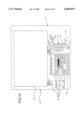
- FIG. 2 is a schematic view showing mechanical configuration of the main body of a copying machine according to the first embodiment.
- an organic photosensitive (OPC) drum 102 having a diameter of 120 mm as an image carrier provided in substantially the center of the main body of the copying machine 101 are an electrifying charger 103 for electrifying the surface of this photosensitive drum, a laser optical system 104 for irradiating the surface of the uniformly electrified photosensitive drum 102 with a semiconductor laser beam to form an electrostatic latent image, a black-developing device 105 for supplying toner for each color to the electrostatic latent image to be developed and obtaining each toner image in each color, three types of developing device 106, 107, 108 for yellow Y, magenta M, and cyan C, an intermediate transfer belt 109 for successively transferring the toner images in each of the colors formed on the photosensitive drum 102, a bias roller 110 for applying a transfer voltage to this intermediate transfer belt 109, a cleaning device 111 for removing toner residues on the surface of the photosensitive drum 102 after the to
- OPC organic photosensitive
- a transfer bias roller 113 for applying a voltage for transferring the toner image transferred along the intermediate transfer belt 109 onto transfer paper and a belt cleaning device 114 for cleaning the image of toner residues on the intermediate transfer belt 109 after the toner image is transferred onto the transfer paper.
- a fixing device 116 for fixing the toner image by being heated or pressured is provided in the exit side of an edge section of a transfer belt 115 for transferring transfer paper peeled from the intermediate transfer belt 109 after the toner image on the intermediate transfer belt 109 is transferred thereonto, and a paper feeder tray 117 is also attached to the exit section of this fixing device 116.
- a contact glass 118 as a document base arranged on the top section of the main body of a copying machine 101 and an exposing lamp 119 for irradiating a document on this contact glass 118 with scanning light are provided in the upper side of the laser optical system 104, and a reflected light from the document is led to an image-formation lens 122 by a reflecting mirror 121 to be introduced into an image sensor array 123 of a CCD as a photoelectric transfer element.
- Image signals converted to electric signals in the image sensor array 123 of a CCD oscillate a semiconductor laser in the laser optical system 104 through the image processing apparatus not shown herein.
- FIG. 3 is a view for explanation of the control system in the main body of the copying machine shown in FIG. 2.
- the control system has a main control section (CPU) 130, and a ROM 131 and a RAM 132 to this main control section 130 are additionally provided therein.
- a main control section 130 Connected to the main control section 130 are also a laser-optical system control section 134, a power supply circuit 135, an optical sensor 136, a toner density sensor 137, an environment sensor 138, a photosensitive body surface potential sensor 139, a toner supplying circuit 140, an intermediate transfer belt driving section 141, and an operating section 142 respectively through an interface I/O 133.
- the laser system control section 134 adjusts laser output from the laser optical system 104, and the power supply circuit 135 gives a specified discharging voltage for electrification to the electrifying charger 103, gives a development bias at a specified voltage to the developing devices 105, 106, 107, 108, and also gives a specified transfer voltage to the bias roller 110 as well as to the transfer bias roller 113.
- the optical sensor 136 comprises light-emitter such as light-emitting diodes or the like and light-receptors such as photosensors or the like each provided adjacent to an area of the image after being transferred from the photosensitive drum 102, and a quantity of deposited toner in a toner image for a detection-pattern latent image formed on the photosensitive drum 102 and a quantity of deposited toner in the background color section are detected for each color respectively, and so-called potential residues on the photosensitive body after electrification thereon is removed is also detected.
- light-emitter such as light-emitting diodes or the like
- light-receptors such as photosensors or the like
- the detection output signal from this photoelectric sensor 136 is applied to the photoelectric sensor control section not shown herein.
- the photoelectric sensor control section computes a ratio between the quantity of deposited toner in the detection-pattern toner image and the quantity of deposited toner in the background color section, compares the ratio value to the reference value to detect fluctuation in an image density, and corrects the control values for the toner density sensor 137.
- the toner density sensor 137 detects a toner density according to changes of magnetic permeability in a developer existing in each of the developing devices 105 to 108.
- the toner density sensor 137 has a function of applying a toner supply signal with amplitude, in a case where the detected toner density value is compared to the reference value and the toner density is found under the specified value which indicates a short of toner therein, corresponding to the shortage thereof to the toner supplying circuit 140.
- the potential sensor 139 detects a surface potential of the photosensitive body 102 as an image carrier, and the intermediate transfer belt driving section 141 controls driving of the intermediate transfer belt 109.
- a developer containing M-toner and carrier is accommodated, for instance, in the magenta-developing device 107 and is agitated in association with rotation of a developer agitating member 202M, so that the developer sucked up onto a sleeve 201M by a developer restricting member is adjusted on the developing sleeve 201M.
- This supplied developer rotates in the direction of rotation of the developing sleeve 201M as a magnetic brush while it is magnetically carried on the developing sleeve 201M.
- developing sleeves 201C, 201Y, and 201B are provided for C-toner, Y-toner, and B-toner, agitated by agitating member 202C, 202Y, and 202B, respectively, as shown in FIG. 2.
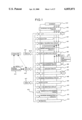
- a color scanner at 402 a shading calibrating circuit, at 403 an RGB ⁇ -calibrating circuit, at 404 an image separating circuit, at 405 an MTF calibrating circuit, at 406 a color conversion-UCR processing circuit, at 407 a scaling circuit, at 408 an image processing (creating) circuit, at 409 an MTF filter, at 410 a ⁇ -calibrating circuit, at 411 a gradation processing circuit, and at 412 a printer.
- a document to be copied is resolved into colors of R, G, B to be read by G, B to be read by the color scanner 401.
- Non-uniformity due to characteristics of an image pickup device or non-uniformity in irradiation of a light source or the like are calibrated in the shading calibrating circuit 402.
- Read signals from the color scanner 401 are converted from data for reflection factors to data for brightness in the RGB ⁇ -calibrating circuit 403. Determination is made between a character section and a photographic section as well as between chromatic color and achromatic color in the image separating circuit 404.
- Degradation of an MTF characteristics in an input system, especially in a high frequency area is calibrated in the MTF calibrating circuit 405.
- the color conversion-UCR processing circuit 406 comprises a color calibration processing section for correcting a difference between color-resolution characteristics in the input system and spectral characteristics of color materials in an output system and computing a rate of color materials for YMC required for faithful color reproduction and a UCR processing for replacing a section in which three colors of YMC are superimposed on each other with Bk (black).
- the color calibration processing in the color calibration processing section can be realized by performing matrix-operation as described below.
- R", G", B” indicate complements of R, G, B respectively.
- Matrix factors a j i are decided depending on spectral characteristics of the input system and output system (color materials).
- an one-dimensional masking equation is used as an example, but by using a second term such as B"2, B" G", or further higher-term, color calibration can more precisely be executed.
- An operation expression may be changed according to a hue, or a Noigebauwer expression may be used.
- Y, M, C can be obtained from values of B", G", R" (or may he B, G, R).
- the UCR processing can be executed by computing using the below equations for each color.
- This ⁇ may be a specified value, or in a high-density section, for instance, ⁇ is close to 1 and in the highlight section, an image in the highlight section can be smoothed by making ⁇ closer to 0.
- a hue determining circuit 422 is connected to between the MTF calibrating circuit 405 and the color conversion-UCR processing circuit 406. Determination is made in this hue determining circuit 422 as to which hue signal among RGBCMY an RGB image signal indicates, and a color conversion coefficient is selected according to each hue.
- the scaling circuit 407 vertical and horizontal scaling is executed, and a repeat processing or the like is executed in the image processing (creating) circuit 408.
- Executed in the MTF filter 409 is processing for changing frequency characteristics of image signals such as edge enhancement or smoothing or the like according to a user's taste to an image such as a sharp image or a soft image or the like.
- Image signals are calibrated in the ⁇ -calibrating circuit 410 according to characteristics of a printer 412. Processing such as eliminating a background color or the like can concurrently be executed also in the ⁇ -calibrating circuit 410.
- Dither processing or pattern processing is executed in the gradation processing circuit 411.
- interfaces I/F 413, 414 for processing image data read by the scanner 401 in an external image processing unit or the like or outputting the image data from the external image processing unit to the printer 412.
- a CPU 415 for controlling the image processing circuit described above, a ROM 416, and a RAM 417 are connected to each other through a BUS 418.
- the CPU 415 is connected to a system controller 419 through a serial I/F, and commands from the operating section or the like not shown herein are sent thereto.
- the reference numeral 421 indicates a pattern generating circuit
- the reference numeral 422 indicates a hue determining circuit
- the reference numeral 423 indicates a selector although particular description is not made therefor herein.
- a write frequency is 18.6 MHz
- a scanning time for 1 pixel is 53.8 nsec.
- 8 bits of image data can be ⁇ -converted with a look up table (LUT) 451.
- the 8 bits of image data are converted to a 8-value pulse width according to signals with the 3 bits at the highest end of the 8 bits of image signal by a pulse width modulator (PWM) 452, are subjected to 32-value power modulation according to signals with the 5 bits at the lowest end by a power modulator (PM) 453, and laser diodes (LD) 454 emit light according to the modulated signals.
- PWM pulse width modulator
- PM power modulator
- LD laser diodes
- Light-emitting amplitude is monitored by a photodetector (PD) 455 to be calibrated each one dot.
- the maximum value by a laser beam amplitude can be changed to 8 bits (256 levels) discretely from image signals.
- a beam diameter (this beam diameter is specified as a width when the beam amplitude is attenuated to 1/e2 while the beam amplitude at rest is the maximum value) in the main scanning direction to a size of one pixel is not more than 90%, and desirably 80%. In conditions of 400 DPI and 63.5 ⁇ m per one pixel, a desirable beam diameter is not more than 50 ⁇ m.
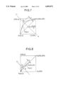
- Step 1001 curvature for the entire section is selected (step 1001), and then curvature for the low image density (highlight) section and that for the high image density (shadow) section are selected (steps 1002, 1003). Then, the curvature for the entire section is multiplied by a factor IDMAX so that the image density has a desired value to prepare a gradation conversion curve (step 1004).
- B indicates a function for changing the curvature of A.
- the Pege function satisfying the above conditions is described as a quadratic Pege curve from a straight line P0P1 connecting a starting point P0 (0, 0) to an endpoint P1 (255, 255) as shown in FIG. 7, a straight line L intersecting this straight line P0P1, and a control point P3 existing on this straight line L and setting a distance d from a point of the intersection of the straight line P0P1 and the straight line L to a parameter.
- t is a parameter in a range of 0 ⁇ t ⁇ 1.
- ⁇ List 1> is rewritten as follows:
- the Pege curve is used, however, in addition, a higher function or an index/a logarithmic function or the like can be used as required.
- curvature for the low image density (highlight) area and a high image density (shadow) area can be changed by executing processing like that in step 1000. So the ⁇ List 1> can be rewritten to a more general form, as follows.
- curvature, h, s indicate values for deciding curvatures for the entire section, highlight section, and shadow section. It should be noted that curvatures for the highlight section and for the shadow section are prepared independently from each other.
- a gradation conversion curve for changing curvature for a particular density area like in a highlight area and a shadow area is generated as described below.
- a gradation conversion curve is generated using a tertiary Pege curve from a straight line P0P1 between a starting point P0 and an endpoint P1, a straight line L intersecting at right angles this straight line P0P1, and a control point P2 existing on this straight line L and setting a distance d from a point of the intersection of the straight line P0P1 and the straight line L to a parameter.
- the control point P3 in the example shown in FIG. 7 is obtained as follows by setting a distance d from the point of intersection of the straight line P0P1 and the straight line L1 as a parameter:
- control point P3 in the second example is obtained as follows by setting a distance d from the point of intersection of the straight line P0P1 and the straight line L1 as a parameter:
- a line segment not included in the line segment P0P1 on the line segment m is used as equivalence conversion for gradation conversion as it is, and areas other than the line segment function as a gradation conversion curve for changing curvature for particular density area like the highlight area as well as the shadow area.
- FIG. 9 is a flow chart showing operations for auto color calibration in an image density
- FIG. 10 is a plan view showing an operating section
- FIG. 11 is a plan view showing a liquid-crystal display screen of the operating section at the time of invoking an ACC menu
- FIG. 12 is a plan view showing a liquid-crystal display screen of the operating section when the performance of the auto color calibration required for using a printer is selected
- FIG. 13 is a plan view showing density gradation patterns on transfer paper when a print-start key is selected
- FIG. 14 is a plan view showing a liquid-crystal display screen of the operating section after the patterns are outputted onto the transfer paper
- FIG. 15 is a plan view showing a liquid-crystal display screen of the operating section during processing for auto color calibration.
- buttons 304 Provided in the upper side of the main body of a copying machine are a plurality of operating buttons 304, as shown in FIG. 10, for executing various type of operations such as preparatory heating/mode clear, memory call, interrupt operation, color adjustment/registration, program, option, and area processing or the like together with a start button 301, a clear/stop button 302, a ten key 303 for setting the number of sheets to be copied or the like each in the front side of the contact glass 118.
- a display screen 305 of a liquid-crystal display unit (described also as a liquid-crystal screen hereinafter) is also provided thereon so that it is surrounded by these buttons.
- the display screen 305 has a tablet function for outputting a signal by pressing a display point or contacting a display point.
- the liquid-crystal screen 305 is switched from the display thereon to the display as shown in FIG. 11.
- [Execute] of the auto color calibration for "copying is used” or "printing is used” is selected, the display on the liquid-crystal screen 305 is changed to the display as shown in FIG. 12.
- the gradation calibration table used when a copier is used is changed, and in a case where "printing is used” is selected, the gradation calibration table used when a printer is used is changed each according to reference data.
- a plurality of density gradation patterns 311 corresponding to each of image quality modes for colors of YMCK, characters and photographs are formed on transfer paper 310 (step 2001 in FIG. 9).
- the reference numeral 312 indicates a position specifying mark.
- the density gradation patterns are previously stored and set in the ROM of the computer 420 shown in FIG. 1.
- a written value for a pattern has 16 patterns such as 00h, 11h, 22h, . . . EEh, FFh displayed in hexadecimal digit.
- a patch for gradation except a background color section is displayed, and an arbitrary value, of 8 bits of signal in 00h to FFh, can be selected.
- dither processing such as pattern processing is not executed, but a pattern is formed in 256 levels per one dot, while in a photograph mode, a written value for a laser is formed by distributing a sum of write values by two pixels each adjacent to each other in the main scanning direction.
- processing of patterns in a case where a written value for a first pixel is n1 and a written value for a second pixel is n2 are distributed as follows:
- Pattern processing used for actual image forming is used other than the above processing.
- a display on the display screen 305 is changed to a display as shown in FIG. 14 so that the transfer paper 310 is mounted on the contact glass 118.
- the transfer paper 310 with the pattern 311 formed thereon is placed on the contact glass 118 (step 2002 in FIG. 9), and "read start" is selected on the display screen 305 as shown in FIG. 14, then the scanner 401 runs, and RGB data for a YMCK density pattern 311 is read (step 2003 in FIG. 9). In this processing, data for the pattern section and data for a background color section of the transfer paper 310 are read.
- the read value for the pattern 311 is calibrated using a RGB calibration value described in detail later (step 2004 in FIG. 9).
- processing for background color data to read data is executed (step 2006 in FIG. 9)
- a YMCK gradation calibration table is prepared and selected (step 2009 in FIG. 9) after processing (step 2008 in FIG. 9) for a high-image density section to the reference data is executed.
- the processing is executed in each of the image quality modes such as for each color of YMCK (step 2010 in FIG. 9), and for photographs and characters (step 2011 in FIG. 9).
- the display on the display screen 305 is changed to that as shown in FIG. 15.
- a key for [return to the original value] is shown on the display screen 305 as shown in FIG. 11 so that, in a case where the operator gets an undesirable result of image forming with the YMCK gradation calibration table after the processing thereof is finished, the operator can select the YMCK gradation calibration table before processing thereof is executed.
- the former is executed to eliminate the difference between whiteness degrees of used transfer paper because, even if images are formed at the same time in the same types of apparatus, values read by the scanner 401 are different from each other.
- the former is executed to eliminate a case where color of a pressure plate for pressing down transfer paper or the like is seen through the paper to be disadvantageously read by the scanner 401 and copied when the transfer paper used for the ACC is not thick enough in its thickness (paper thickness).
- paper thickness For instance, in a case where an auto document feeder called as ADF is mounted in place of a pressure plate, a belt is used for carrying a document, paper has a low whiteness degree and sometimes has slightly grayish white because of a rubber based material used for this belt.
- an image signal to be read is read as a signal for an image over which the density is apparently higher than original one, so that, when a YMCK gradation calibration table for the image is prepared, the density therefor is intentionally made lower by the degree to be the original one.
- the image is reproduced as one in a low density on the whole, so that a desirable image can not always be obtained.
- a image signal read from the pattern section is calibrated according to an image signal from the background color section of the paper.
- keys for calibrating or not calibrating a background color are displayed on the display screen 305 so that the calibration of the background color can be ON or OFF according to the user's conditions and taste.
- a gradation pattern may be described by brightness, chroma, hue angle (L*, c*, h*), or brightness, redness, blueness (L*, a*, b*) or the like. It is also assumed that read values for white color as reference values previously stored in the ROM 416 or RAM 417 are set to values (r[W], g[W], b[W]).
- read values for a pattern ( ⁇ r[t][k], ⁇ g[t][k], ⁇ b[t][k]) is obtained as follows from read values (r[t][i], g[t][i], b[t][i]) for RGB signals to each of YMCK toner:
- ⁇ k[s][t]1 ⁇ in expression (10) indicates that a decimal close to a numeral 1 is taken, but inside a copying machine, it is held as integer data as described below:
- K[s][t] which are calibration values for RGB signals obtained as described above are shown in Table 1.
- Calibration data for the RGB signals shown in Table 1 is displayed, as shown in FIG. 19, on the display screen 305 of the operating section in the main body of the copying machine 101, and those numerical values can be inputted by pressing down with a finger the corresponding section in the display area. Inputted data is stored in the RAM 417.
- the calibrated values are set to new values (r[t][i], g[t][i], b[t][i]), and are used as follows.
- image signals for each complementary color of YMC toner are b[t][i], g[t][i], r[t][i]respectively, so that only image signals for complementary colors are used.
- a gradation conversion table is prepared, which makes the processing simple. It should be noted that, even if any image signal of RGB is used, sufficient precision can be obtained as far as black toner is concerned, however, a G (green) element is used.
- a YMCK gradation conversion table can be obtained by comparing the a[LD] described above to the reference data A[n] stored in the ROM 416.
- n indicates an input value to the YMCK gradation conversion table
- the reference data A[n] indicates a target value for a read image signal that the YMC toner pattern outputted at a laser write value LD[i] after the input value [n] is subjected to YMCK gradation conversion is read by a scanner.
- the reference data A[n] has two type of reference data, one of which is one for executing calibration according to an image density enabling output by a printer, and the other of which is one for not executing calibration. Determination is made as to whether calibration is executed or not according to the data for determination, described later, previously stored in the ROM 416 or the RAM 417. This calibration is described later.
- FIG. 16 is a graph for explanation of calibration of a background color.
- the X-axis in the upper right quadrant (a) of FIG. 16 indicates an input value n to the YMCMK gradation conversion table and the Y-axis therein indicates a value (after the processing) read by the scanner 401, which indicates the reference data A[1] described above.
- the value (after the processing) read by the scanner 401 is a value, in contrast to a value obtained by reading a gradation pattern by the scanner 401, obtained by RGB ⁇ -converting (conversion is not executed here), averaging and adding the read data in some points of the gradation pattern, and the obtained value is processed herein as 12 bits of data to improve operational precision.
- the X-axis in the upper left quadrant (b) thereof indicates a value (after the processing) read by the scanner 401 like in the Y-axis.
- the Y-axis in the lower left quadrant (c) indicates a written value by a laser beam (LD). This data a[LD] indicates characteristics of a printer.
- the write value by a laser beam (LD) for actually formed pattern includes 16 values in total such as 00h (a background color), 11h, 22h, . . . , EEh, FFh, which indicate values by skipping therebetween, however, values not detected between the detected points are interpolated herein, so that the graph is regarded as a continuous graph.
- the graph in the lower right quadrant (d) thereof indicates a YMCK gradation conversion table LD[1] which is an object to be obtained.
- Values of the X-axis and Y-axis of the graph (f) are the same as those in the graph (d).
- the YMCK gradation conversion table (g) shown in the graph (f) is used.
- the X-axis of the last graph (e) is the same as that in the lower left quadrant (c), which indicates linear conversion for the convenience to show a relation between the write values of LD when a gradation patter is prepared and values read by the scanner 401 (after the processing).
- the reference data A[n] corresponding to an input value n is obtained from the graph shown in FIG. 16, and LD output LD[n] to obtain A[n] is obtained along the arrow (1) in the figure using the read value a[LD] for the gradation pattern.
- FIG. 17 is a flowchart showing a sequence of preparing a gradation conversion table when the ACC is executed.
- the reference data A[n] is calibrated according to an image density in which an image can be outputted onto a printer 412 (step 3002).
- read values by a laser in which the maximum image density enabling preparation by the printer 412 can be obtained is set to FFh (indicated by hexadecimal) and the read value m[FFh]for a pattern at this time is set to mmax.
- a signal is an image signal to which RGB ⁇ -conversion is not executed and which is proportional alto a reflection factor of a document.
- a difference ⁇ ref between the data is computed from the reference data A[i2+1] with the lowest image density in a high image density section as well as from the reference data A[i1] with the lowest image density in a low image density section.
- ⁇ ref is larger than 0 ( ⁇ ref>0).
- ⁇ det is computed from the read value mmax for a pattern with which the maximum image density enabling preparation by the printer 412 can be obtained. Namely, it is assumed as follows:
- the read image signal m[i] by the scanner 401 corresponding to the n[i] obtained in step 3001 is obtained from the reference data A[n] (step 3003).
- a value m[i] is obtained from the following expression using the value j computed as described above:
- step 3003 write values LD[i] by LD to obtain m[i] computed in step 3003 is obtained according to the same sequence as that in step 3003 (step 3004).
- FIG. 18 is a flowchart showing a sequence for selecting a gradation conversion table during execution of ACC.
- coefficient IDMAX [%] applied to the entire ⁇ -calibration table (step S4001) is computed.
- IDMAX is set to LD[imax]/FFh ⁇ 100[%].
- curvature h, and s which are indices for curved section of the whole section, highlight section, and shadowed section respectively, are selected.
- the curvature m for the whole section is selected (step S4002). Basically m is selected so that a sum of square of errors between the finally obtained gradation conversion curve E[j] (0 ⁇ j ⁇ 255) and a set (n[i], LD[i]) (0 ⁇ i ⁇ 15) of the input value n[i] into the YMCK ⁇ -calibration table and the output value LD[i] (described as error hereinafter) will be minimum,
- wi is weight to an input value to the i-th YMCK ⁇ calibration table.
- curvature h for a highlight section which should have a minimum error is obtained (step S4003), and then curvature s for a shadowed error which should also have a minimum error is obtained (step S4004).
- the (h -- min, m -- min, s -- min) obtained as described above and IDMAX are used as new curvature of the calibrated gradation curve.
- FIG. 20 is a general block diagram showing an example of configuration for setting and inputting calibration values for RGB signals
- FIG. 21 is a block diagram showing electric configuration of the system shown in FIG. 20
- FIG. 22 is a flow chart showing a sequence for setting and inputting calibration values for RGB signals in a form according to the second embodiment of the present invention
- FIG. 23 is a flat view showing an example of color patch transferred onto transfer paper.
- a computer 321 which is a computing device for computing calibration values for RGB signals, is connected with a wired communication means to the main body of copying machine 101 so that bi-directional communication can be made.
- the computer 321 comprises a computer for control which can also process data. It should be noted that the main body of copying machine 101 and the computer 321 may be connected to each other with a radio communicating means. Copying machine 101 is arranged to accept a YMCK color patch 324 and discharge a transfer paper 311, as described hereinafter.
- the main body of copying machine 101 has a non-volatile RAM 322, and reads color patch having a known spectral reflection characteristic.
- a memory device 323 is connected to the computer 321.
- a YMCK color patch 324 having a known spectral reflection characteristics is placed on a contact glass 118 of the main body of the copying machine (step S5001).
- the color patch 324 comprises a color patch printed with YMCK ink or the like when transferred onto transfer paper 311 as shown in FIG. 23.
- FIG. 23 shows two types of color tone for each of YMCK, but the color tone may be one type.
- the scanner 401 of the main body of the copying machine 101 the color patch 324 is read, and read values for RGB signals are obtained (step S5002).
- the read values for this color patch 324 are down-loaded to a computer 321 which is an external computing device (step S5003).
- step S5005 calibration values for RGB signals obtained from the computer 321 are up-loaded to the main body of the copying machine 101.
- step S5006 the main body of the copying machine 101 stores the obtained calibration values for RGB signals in the non-volatile RAM 322.
- Calibration values for RGB signals are prepared with the computer 321 as described above, and the calibration values are transferred to the main body of the copying machine 101 and stored in the non-volatile RAM 322 in the main body of the copying machine 101.
- the calibration values for RGB signals stored in the non-volatile RAM 322 are transferred to the CPU 130 just after power for the main body of the copying machine 101 is turned ON, and are stored in the RAM 132 of the CPU 130.
- the calibration value for RGB signals stored in the RAM 132 of the CPU 130 are used in execution of the ACC described above.
- the processing is executed as described below.
- FIG. 24 is a block diagram showing another example of setting and inputting calibration values for RGB signals
- FIG. 25 is a flowchart showing a sequence for setting and inputting calibration values for RGB signals in FIG. 24.
- the configuration is the same as that shown in FIG. 21 excluding the point that a toner patch 324a is obtained from the main body of the copying machine 101, so that duplicated description is omitted herein.
- the sequence from step S6002 to step S6007 is completely the same as a sequence from step S5001 to step 5006 in FIG. 22 excluding the step 6001 for placing the color patch 324 on the contact glass 118 of the basic body of the copying machine 101, so that also description of the steps is omitted herein.
- A is a proportional al constant
- ⁇ is a wavelength
- FIG. 26 is a general block diagram showing still another example of configuration for setting and inputting calibration values for RGB signals
- FIG. 27 is a block diagram showing electric configuration of the system shown in FIG. 26
- FIG. 28 is a block diagram showing electric configuration of a case where a color patch prepared with toner in the configuration shown in FIG. 26 is used
- FIG. 29 is a flow chart showing a sequence for setting and inputting calibration values for RGB signals in FIG. 27 and FIG. 28.
- the configuration shown in FIG. 26 are the same as that shown in FIG. 20 excluding the point that a spectrographic color measuring instrument 331 is connected to the computer 321.
- the image density adjustor 332 comprises a computer 321, a storage device 323, and the spectrographic color measuring instrument 331.
- a toner patch 324a prepared with toner is prepared with the main body of the copying machine 101, so that the blocks as shown in FIG. 28 are provided.
- a color patch is outputted (step S7001). Then the YMCK color patch having a known spectral reflection characteristic is placed on the contact glass 118 of the document base of the main body of the copying machine 101 (step S7002). Then, with the color scanner 401 of the main body of the copying machine 101, the color patch is read to obtain read values for RGB signals (step S7003).
- step S7004 read values for the color patch from the main body of the copying machine 101 is down-loaded (step S7004), and the outputted color patch outputted from the main body of the copying machine 101 is read with the spectrographic color measuring instrument 331 (step S7005).
- the calibration values for RGB signals obtained from the computer 321 are up-loaded to the main body of the copying machine 101 (step 7007) and are stored in the non-volatile RAM 322 in the main body of the copying machine 101 (step 7008).
- the processing through the expression (17) may be executed by previously storing the values for the expression (16) in the non-volatile RAM 322 or ROM 416 of the main body of the copying machine 101.
- the YMCK gradation pattern (color patch) is placed on the contact glass 118 of a document base of the main body of the copying machine 101 (step S8001), and the color patch is read with the color scanner 401 of the main body of the copying machine 101 to obtain read values for RGB signals (step 8002).
- the calibration values for RGB signals obtained as described above are stored in the non-volatile RAM 322 in the main body of the copying machine 101 (step 8004).
- the calibration values for RGB may be set.
- the calibration values may be stored in the memory card so that the calibration values can be read out when the image forming apparatus is used.
- an image signal conversion table is prepared and selected according to read values read for a gradation pattern, but also an image signal conversion table is prepared and selected according to read signals read for gradation patterns formed on a transfer member as well as to reference data (gradation target data) corresponding to read signals for gradation patterns stored in a storing means.
- reference data grade target data
- Ar, Ag, and Ab are reference data for a red signal, a green signal, and a blue signal respectively, while YMCK indicates a color of toner.
- the above expression (19) indicates that a probable input value into a gradation conversion table, namely reference data corresponding to any of 256 values from 0 to 255 are stored on a memory with the processing for 8-bit signal.
- reference data consisting of 256 values as described above
- the calibration data for the RGB signals shown in Table 1 is, as shown in FIG. 19, displayed on a display screen 305 of an operating section of the main body of the copying machine 101, and the numerical values can be inputted by pressing a section corresponding to a section to be displayed with a finger.
- the inputted data is stored in the RAM 417.
- red value is an 8-bit signal
- this value is in a range from 0 to 25
- value 0 indicates the darkest image density, namely a quantity of light detected by a CCD in the scanner 401 when an object with a low reflection factor or a low transmission factor is read
- value 255 indicates the brightest image density, namely a quantity of light detected by a CCD in the scanner 401 when an object with a high reflection factor or a high transmission factor is read.
- Ar[C][0], Ag[C][0], and Ab[C][0] are values obtained when the background color section of the paper is read. It should be noted that, when reading a background color section of paper, it is possible to prevent the precision from becoming lower by setting several sheets of white paper to make up so-called the white back so that the backing for the paper will not become dark.
- i in the expression (22) is in a range from 0 to 10.
- n[0] namely in a case where an input value into the gradation conversion table is 0 (zero)
- calibration by the expression (22) should not be performed.
- the values of k[r][C], k[g][C], and k[b][C] used in the expression (22) are not equal to the values of k[r][C], k[g][C], and k[b][C] used in the expression (21) , and it is necessary to change the numerical values to appropriate ones for each expression.
- Image signals for complementary colors for YMC toners are blue, green, and red respectively, and to simplify the processing, of the reference data Ar[t][i], Ag[t][i], and Ab[t][i], the reference data Ab[t][i], Ag[t][i], and Ar[t][i] for complementary colors for the toners are used.
- This treatment is effective in a case where the spectral (reflection) characteristic of used toner does not change largely, namely in a case where the color taste does not change.
- the following expression is used:
- the read signal is expressed using only an image signal for the complementary color as follows:
- FIG. 31 is a flowchart showing a sequence for preparing a gradation conversion table in execution of ACC.
- step S3001 an input value required for preparation of a YMCK ⁇ -calibration table is computed (step S3001).
- the reference data A [n] is calibrated with a calibration value k[s][t] for RGB signal according to the sequence described above (step S3002).
- the reference data A[n] is calibrated according to an image density which can be outputted from the printer 412 (step 3002a).
- a read value for a laser bean which makes it possible to obtain the maximum image density obtainable with the printer 412 is FFh (displayed in a form of hexadecimal form), and also that the read value m [FFh] for the pattern then is mmax.
- the ⁇ ref is larger than 0.
- the different ⁇ det is computed from the read value mmax for the pattern with the maximum image density obtainable with the printer 412. Namely the following expression is applicable:
- an image signal n[i] read by the scanner 401 corresponding to n[i] obtained in step 3001 is obtained from the reference data A[n] (step 3003).
- a target value m[i] is obtained from j obtained as described above through the following expression:
- interpolation is performed with a linear expression, but interpolation may be formed with a high-order function or a spline function. In that case,
- step 3003 a written value LD[i] for LD to obtain the target value m[i] obtained in step S3003 is obtained through a sequence similar to that in step 3003 (step 3004).
- This type of setting is employed because, as values for a quantity of deposited toner read by the scanner 401 largely changes in an area with image density corresponding to a small quantity of deposited toner, gap between written value LD[k] for a pattern is made smaller to read the area, and also as values for a quantity of deposited toner read by the scanner 401 little changes in an area with image density corresponding to a large quantity of deposited area, the gap be made larger to read the area.
- an image forming apparatus As understood from the description above, with an image forming apparatus according to the present invention, it is possible to correct spectral sensitivity of an image reading means varying unit by unit and to obtain a gradation calibration table for obtaining good gradations. Also it is possible to prepare a YMCK gradation calibration table for obtaining good color balance in a color image forming apparatus.
- an image forming apparatus With an image forming apparatus according to the present invention, a service man or a user can easily obtain a desired image by freely changing a calibration value previously set in an operating section of an image forming apparatus.
- an image forming apparatus when non-uniformity of spectral sensitivity of an image forming means which will vary from unit to unit can be calibrated in the assembly step by inputting a value for calibration from the device provided outside the image forming apparatus, and with this feature a calibration value can easily be set in each image forming apparatus.
- an appropriate value can easily be set as a calibration value according to the change, and a serviceman or a user can set an appropriate calibration value with simple operations.
- an image forming apparatus With an image forming apparatus according to the present invention, it is possible to correct spectral sensitivity of an image reading means which varies unit by unit and also to prepare a YMCK gradation calibration table for obtaining good color balance and gradations by executing ACC.
- a ratio between RGB read values for YMCK toner being used for the image reading means can be inputted according to the necessity, and a read value for YMCK toner can always be calibrated to an appropriate value.
- a serviceman or a user can input an appropriate calibration value into an operating section of an image forming apparatus, so that a gradation calibration table for obtaining good color balance and gradations can be obtained by executing ACC.
- data for calibrating non-uniformity in spectral sensitivity of an image reading means which varies for each image forming apparatus can be prepared or set with a device provided outside the image forming apparatus in the assembly step, so that data can rapidly be set in the image forming apparatus.
Abstract
Description
Y'=Y-α·min(Y, M, C) (2)
M'=M-α·min(Y, M, C) (3)
C'=C-α·min(Y, M, C) (4)
Bk=α·min(Y, M, C) (5)
______________________________________
<List 1>
______________________________________
typedef int Table[256];
Table A, E;
int  B( int A, in curvature)
int  value;
/*  Computing for changing curvature  */
according to a degree of curvature
. . .
return  value;
}
Processing for changing
/* full() : curvature for the entire section */
Table  full(int curvature)
{
/* curvature is a degree of curve  */
int  i;
for(i = 0; i < = 255; i+ +)
E[i] = B( A[i],  curvature);
return  E;
}
______________________________________
P(d, t)=P0·t.sup.3 +2P2(d)t(1-t)+P1(1-t).sup.3 (7)
______________________________________
const   table.sub.-- max = 9:
typedef int  Table[256];
Table   A, E, B[table.sub.-- max = 9;
Processing for changing
/*(): curvature of the entire sectian
Table  full(int curvature)
curvature specifies a degree
/*  of curve.    */
int  i;
for (i = 0; i < = 255; i+ +)
E[i] = B[curvature][ A[i] ]:
return   E;
}
main()
{
/* curvature is a degree of curve   */
int   curvature = 1;
E = full( curvature);
}
______________________________________
______________________________________
<List 3>
______________________________________
const   table.sub.-- max = 9;
typedef int Table[256];
Table A, E, B[table.sub.-- max];
Processing for changing
/* Transform(): curvature      */
Table  Transform(Table Transformer, Table Original)
/*This function executes curvature of the*
*gradatian conversion curve called Original*
using the gradation conversion curve
*called Transformer */
int  i;
for(i = 0;i < = 255;i+ +)
E[i] = Transformer[ Original[i] ];
returu E;
}
main()
{
/* curvature is a degree of curve  */
int  curvature = 1;
E = Transform( B[curvature], A);
Curvature of gradation conversion curve A is
/* changed using the gradation conversion curve B*
*[curvature]  */
}
______________________________________
______________________________________
<List 4>
______________________________________
const   table.sub.-- max =9;
typedef int  Table[2569 ;
Table   A, B[table.sub.-- max], E, CH[table.sub.-- max], CS[table.sub.--
max];
Processing for
/* Transform(): changing curvature    */
Table  Transform( Table Transformer, Table Original);
main()
int   curvature, h, s;
/*Curvature of a curve is changed by changing numerical values
of curvature, h, s */
/* Curvature of the entire section is changed */
E = Tranform( B[curvature, A):
Curvature of the low image density
/*(highlight) section is changed   */
E = Tranform( CH[h], E):
Curvature of high image density
/* (shadowed) section is changed   */
E = Tranform( CS[s], E):
}
______________________________________
P3(d)=(16, 16)+(-d/√ 2, d/√ 2)
P3 (d)=(16, 16)+(0, d)
P(d, t)=P0·t.sup.3 +3·P2·t.sup.2 ·(1-t)+3·P3(d)·t·(1-t).sup.2 +P1·(1-t).sup.3 (8)
Δr[t][k]=r[W]-r[t][k],
Δg[t][k]=g[W]-g[t][k],
Δb[t][k]=b[W]-b[t][k] (9)
k[s][t]{s=R,G, or B; t=Y,M,C, or K|k[s][t]1} (10)
k[s][t]=k1[s][t]/2.sup.n (k1[s][t] is an integer of 2.sup.n)
              TABLE 1
______________________________________
Calibration values for RGB signals:k [s] [t]
t       R              G      B
______________________________________
K       1.00           1.00   1.00
C       1.05           1.00   0.95
M       1.00           1.00   1.00
Y       1.00           1.00   0.95
______________________________________
r1[C][i]=r[C][0]-Δr[t][k]×k[r][t]
g1[C][i]=g[C][0]-Δg[t][k]×k[g][t]
b1[C][i]=b[C][0]-Δb[t][k]×k[b][t]
A[t][n[i]](0≦n[i]≦255, i=1, 2, . . . , 10, t=Y, M, C, or K)
Δref=A[i1]-A[i2+1] (11)
Δdet=A[i1]-mmax (12)
A[i]=A[i1]+(A[i]-A[i1])×(Δdet/Δref) (i=i1+1, i1+2, . . . , i2-1, i2) (13)
m[i]=A[j]+(A[j+1])-A[i])·(n[i]-n[j])/(n[j+1]-n[j])(14)
m[i]=f(n[i])
a[LD[k]]≧a[LD[k+1]]
a[LD[k+1]]≧m[i]>a[LD[k+1]], LD[i]=LD[k]+(LD[k+1]-LD[k])·(m[i]-a[LD[k]]/(a[LD[k+1]]-a[LD[k]])
LD[i]=LD[k]+(LD[kmax]-LD[kmax-1])·(m[i]-a[LD[kmax-1]])/(a[LD[kmax]]-a[LD[kmas-1]])
error=Σwi·(LD[i]-E[n[i]]).sup.2
Δv[t][s]=v[W][s]-v[t][s] (15)
Δv0[t][s]=v0[W][s]-v0[t][s] (16)
k[t][s]=Δv0[t][s]/Δv[t][s] (17)
Δv0[t][s]=A E0(λ)ρ(t, λ)τ0(s, λ)dλ(18)
Ar[t][n](0≦n≦255, t=Y, M, C, or K)
Ag[t][n](0≦n≦255, t=Y, M, C, or K)
Ab[t][n](0≦n≦255, t=Y, M, C, or K) (19)
n[i](0≦n≦255, i=0, 1, . . . , 10)
Ar[t][n[i]](0≦n≦255, i=0, 1, . . . , 10 t=Y, M, C, or K)
Ag[t][n[i]](0≦n≦255, i=0, 1, . . . , 10 t=Y, M, C, or K)
Ab[t][n[i]](0≦n≦255, i=0, 1, . . . , 10 t=Y, M, C, or K)
Arl[C][n[i]]=Ar[W]+(Ar[C][n[i]]-Ar[W])×k[r][C]
Agl[C][n[i]]=Ag[W]+(Ag[C][n[i]]-Ag[W])×k[g][C]
Abl[C][n[i]]=Ab[W]+(Ab[C][n[i]]-Ab[W])×k[b][C] (21)
Ar[W]=Ar[C][0]
Ag[W]=Ag[C][0]
Ab[W]=Ab[C][0]
A[t][n[i]](0≦n[i]≦255, i=0, 1, . . . , 10; t=C, M, Y)
a[t][i](i=0, 1, . . . , 9; t=C, M, Y, K)
Δref=A[i1]-A[i2+1] (23)
Δdet=A[i1]-mmax (24)
A[i]=A[i1]+(A[i]-A[i1]×(Δdet/Δref) (i=i1, i1+2, . . . , i2-1, i2) (25)
m[i]=A[j]+A[j]+(A[j+1]-A[i])·(n[i]-n[j])/(n[i+1]-n[i])(26)
m[i]=f(n[i])
LD[k]<LD(k+1)
a[LD[k]]≧a[LD[k+1]]
a[LD[k]]≧m[i]>a[LD[k+1]]
LD[i]=LD[k]+(LD[k+1]-LD[k])·(m[i]-a[LD[k]])/(aLD[k+1]-a[LD[k]])
LD[i]=LD[k]+(LD[kmax]-LD[kmax-1])·(m[i]-a[LD[kmax-1]])/(aLD[kmax]-a[LD[kmax-1]])
Claims (12)
Applications Claiming Priority (6)
| Application Number | Priority Date | Filing Date | Title |
|---|---|---|---|
| JP11672396 | 1996-05-10 | ||
| JP29654296 | 1996-11-08 | ||
| JP8-116723 | 1996-11-08 | ||
| JP8-296542 | 1996-11-08 | ||
| JP9-109257 | 1997-04-25 | ||
| JP10925797A JP3678875B2 (en) | 1996-05-10 | 1997-04-25 | Image forming apparatus |
Publications (1)
| Publication Number | Publication Date |
|---|---|
| US6055071A true US6055071A (en) | 2000-04-25 |
Family
ID=27311429
Family Applications (1)
| Application Number | Title | Priority Date | Filing Date |
|---|---|---|---|
| US08/854,111 Expired - Lifetime US6055071A (en) | 1996-05-10 | 1997-05-09 | Image forming apparatus |
Country Status (3)
| Country | Link |
|---|---|
| US (1) | US6055071A (en) |
| JP (1) | JP3678875B2 (en) |
| DE (1) | DE19719742C2 (en) |
Cited By (39)
| Publication number | Priority date | Publication date | Assignee | Title |
|---|---|---|---|---|
| US6118557A (en) * | 1994-12-07 | 2000-09-12 | Ricoh Company, Ltd. | Color image forming apparatus |
| US6185007B1 (en) * | 1997-08-20 | 2001-02-06 | Ricoh Company, Ltd. | Image forming apparatus |
| US20020021827A1 (en) * | 2000-08-18 | 2002-02-21 | Cross Match Technologies, Inc. | Fingerprint scanner auto-capture system and method |
| US20020051234A1 (en) * | 1998-03-31 | 2002-05-02 | Ravishankar Rao | Smoothing calibration files to improve reproduction of digitized images |
| US20030002096A1 (en) * | 2001-03-28 | 2003-01-02 | Naoki Sugiyama | Image forming apparatus and masking coefficient calculation method |
| US20030007686A1 (en) * | 2001-06-29 | 2003-01-09 | Roever Jens A. | Combined color space matrix transformation and FIR filter |
| US20030042399A1 (en) * | 2001-06-19 | 2003-03-06 | Umax Data Systems Inc. | Calibration method of an image-capture apparatus |
| US20030142856A1 (en) * | 2002-01-17 | 2003-07-31 | Cross Match Technology, Inc. | Biometric imaging system and method |
| US20030197593A1 (en) * | 2002-04-19 | 2003-10-23 | Cross Match Technologies, Inc. | Systems and methods utilizing biometric data |
| US6658164B1 (en) * | 1999-08-09 | 2003-12-02 | Cross Match Technologies, Inc. | Calibration and correction in a fingerprint scanner |
| US20040001210A1 (en) * | 2002-06-27 | 2004-01-01 | Compaq Information Technologies Group, L.P., A Delaware Corporation | Method and system for characterizing printer color |
| US20040016811A1 (en) * | 2002-04-19 | 2004-01-29 | Cross Match Technologies, Inc. | Mobile handheld code reader and print scanner system and method |
| US6687391B1 (en) | 1999-10-22 | 2004-02-03 | Cross Match Technologies, Inc. | Adjustable, rotatable finger guide in a tenprint scanner with movable prism platen |
| US6714673B1 (en) * | 1999-09-17 | 2004-03-30 | Canon Kabushiki Kaisha | Image processing method and apparatus, and recording medium therefor |
| US20040130739A1 (en) * | 2000-01-05 | 2004-07-08 | Adam George E. | Scanner and printer profiling system |
| US20040170303A1 (en) * | 2003-02-28 | 2004-09-02 | Cross Match Technology, Inc. | Dynamic image adaption method for adjusting the quality of digital prints |
| US20040239996A1 (en) * | 2003-03-20 | 2004-12-02 | Koji Hayashi | Image processing system, image forming system, computer program, and recording medium |
| US20050047631A1 (en) * | 2003-08-26 | 2005-03-03 | Cross Match Technologies, Inc. | Method and apparatus for rolled fingerprint image capture with variable blending |
| US20050057742A1 (en) * | 2002-01-17 | 2005-03-17 | Cross Match Technologies, Inc. | Light wedge for illuminating a platen in a print scanner |
| US20050073703A1 (en) * | 2003-10-07 | 2005-04-07 | Kabushiki Kaisha Toshiba | Image processing device and method for performing gamma correction |
| US20050100196A1 (en) * | 1998-04-28 | 2005-05-12 | Cross Match Technologies Inc. | Methods for capturing fingerprint images using a moving platen |
| US6912064B1 (en) * | 1998-08-07 | 2005-06-28 | Seiko Epson Corporation | Image forming apparatus and image forming method using the same |
| US20050220356A1 (en) * | 1998-09-18 | 2005-10-06 | Canon Kabushiki Kaisha | Image processing apparatus, image processing method, and recording medium |
| US20050231576A1 (en) * | 2001-06-22 | 2005-10-20 | Lee David L | Color reproduction process |
| US20050280866A1 (en) * | 2004-06-04 | 2005-12-22 | Brother Kogyo Kabushiki Kaisha | Density-adjusting device |
| US6992796B1 (en) | 1999-09-03 | 2006-01-31 | Sharp Kabushiki Kaisha | Image forming apparatus and image processing method used for the same |
| US20060133656A1 (en) * | 2002-08-02 | 2006-06-22 | Cross Match Technologies, Inc. | System and method for counting ridges in a captured print image |
| US20060139778A1 (en) * | 2001-04-26 | 2006-06-29 | Cross Match Technologies, Inc. | Silicone rubber surfaces for biometric print TIR prisms |
| US20060170906A1 (en) * | 2002-01-17 | 2006-08-03 | Cross Match Technologies, Inc. | Systems and methods for illuminating a platen in a print scanner |
| US20070223064A1 (en) * | 2006-03-23 | 2007-09-27 | Konica Minolta Business Technologies, Inc. | Image reading apparatus, image processing method and computer-readable recording medium |
| US20070285743A1 (en) * | 2006-06-09 | 2007-12-13 | Kabushiki Kaisha Toshiba | Image forming apparatus and image forming method |
| US20090109508A1 (en) * | 2007-10-24 | 2009-04-30 | Seiko Epson Corporation | Image Processing Method, Program for Image Processing, and Image Processing Apparatus |
| US20090141295A1 (en) * | 2007-11-29 | 2009-06-04 | Koji Hayashi | Image processing apparatus |
| US20140029020A1 (en) * | 2012-07-30 | 2014-01-30 | Ricoh Company, Ltd. | Image forming apparatus, image forming method, and computer-readable medium |
| US8655067B2 (en) | 2010-05-24 | 2014-02-18 | Ricoh Company, Limited | Image processing apparatus, image processing method, and computer program product |
| US20150015657A1 (en) * | 2013-07-10 | 2015-01-15 | Canon Kabushiki Kaisha | Printing apparatus |
| US20150015923A1 (en) * | 2013-07-12 | 2015-01-15 | Ricoh Company, Ltd. | Image forming apparatus and image forming method |
| US20170236041A1 (en) * | 2016-02-16 | 2017-08-17 | Ricoh Company, Ltd. | Halftone Calibration Mechanism |
| US20230154399A1 (en) * | 2019-03-07 | 2023-05-18 | Stereyo Bvba | Real-time deformable and transparent display |
Families Citing this family (1)
| Publication number | Priority date | Publication date | Assignee | Title |
|---|---|---|---|---|
| JP4645531B2 (en) * | 2006-05-31 | 2011-03-09 | 富士ゼロックス株式会社 | Correction characteristic generation apparatus, program, and color signal conversion apparatus |
Citations (13)
| Publication number | Priority date | Publication date | Assignee | Title |
|---|---|---|---|---|
| JPS63208370A (en) * | 1987-02-25 | 1988-08-29 | Canon Inc | Color image forming method |
| JPS63303370A (en) * | 1987-06-03 | 1988-12-09 | Konica Corp | Color image forming device |
| US5194945A (en) * | 1987-08-11 | 1993-03-16 | Canon Kabushiki Kaisha | Color image processing apparatus |
| JPH05114962A (en) * | 1991-10-22 | 1993-05-07 | Canon Inc | Image forming device |
| JPH07193686A (en) * | 1993-12-27 | 1995-07-28 | Canon Inc | Device and method for forming image |
| EP0674429A2 (en) * | 1994-03-25 | 1995-09-27 | Eastman Kodak Company | Field calibration method and apparatus for color image reproduction system |
| JPH07298075A (en) * | 1994-04-28 | 1995-11-10 | Canon Inc | Image forming system and its image processing method |
| EP0685962A2 (en) * | 1994-06-03 | 1995-12-06 | Xerox Corporation | Printer color and gray balance adjustment system |
| US5508826A (en) * | 1993-04-27 | 1996-04-16 | Lloyd; William J. | Method and apparatus for calibrated digital printing using a four by four transformation matrix |
| US5585927A (en) * | 1992-05-19 | 1996-12-17 | Minolta Camera Kabushiki Kaisha | Digital image forming apparatus having gradation characteristic setting means |
| US5754683A (en) * | 1993-12-10 | 1998-05-19 | Mita Industrial Co., Ltd. | Image forming apparatus and gradation output adjusting method in image forming apparatus |
| US5764378A (en) * | 1994-12-12 | 1998-06-09 | Fuji Xerox Co., Ltd. | Image forming apparatus |
| US5767991A (en) * | 1994-05-26 | 1998-06-16 | Fuji Xerox Co., Ltd. | Color image reading device |
-
1997
- 1997-04-25 JP JP10925797A patent/JP3678875B2/en not_active Expired - Fee Related
- 1997-05-09 DE DE19719742A patent/DE19719742C2/en not_active Expired - Fee Related
- 1997-05-09 US US08/854,111 patent/US6055071A/en not_active Expired - Lifetime
Patent Citations (13)
| Publication number | Priority date | Publication date | Assignee | Title |
|---|---|---|---|---|
| JPS63208370A (en) * | 1987-02-25 | 1988-08-29 | Canon Inc | Color image forming method |
| JPS63303370A (en) * | 1987-06-03 | 1988-12-09 | Konica Corp | Color image forming device |
| US5194945A (en) * | 1987-08-11 | 1993-03-16 | Canon Kabushiki Kaisha | Color image processing apparatus |
| JPH05114962A (en) * | 1991-10-22 | 1993-05-07 | Canon Inc | Image forming device |
| US5585927A (en) * | 1992-05-19 | 1996-12-17 | Minolta Camera Kabushiki Kaisha | Digital image forming apparatus having gradation characteristic setting means |
| US5508826A (en) * | 1993-04-27 | 1996-04-16 | Lloyd; William J. | Method and apparatus for calibrated digital printing using a four by four transformation matrix |
| US5754683A (en) * | 1993-12-10 | 1998-05-19 | Mita Industrial Co., Ltd. | Image forming apparatus and gradation output adjusting method in image forming apparatus |
| JPH07193686A (en) * | 1993-12-27 | 1995-07-28 | Canon Inc | Device and method for forming image |
| EP0674429A2 (en) * | 1994-03-25 | 1995-09-27 | Eastman Kodak Company | Field calibration method and apparatus for color image reproduction system |
| JPH07298075A (en) * | 1994-04-28 | 1995-11-10 | Canon Inc | Image forming system and its image processing method |
| US5767991A (en) * | 1994-05-26 | 1998-06-16 | Fuji Xerox Co., Ltd. | Color image reading device |
| EP0685962A2 (en) * | 1994-06-03 | 1995-12-06 | Xerox Corporation | Printer color and gray balance adjustment system |
| US5764378A (en) * | 1994-12-12 | 1998-06-09 | Fuji Xerox Co., Ltd. | Image forming apparatus |
Cited By (60)
| Publication number | Priority date | Publication date | Assignee | Title |
|---|---|---|---|---|
| US6118557A (en) * | 1994-12-07 | 2000-09-12 | Ricoh Company, Ltd. | Color image forming apparatus |
| US6185007B1 (en) * | 1997-08-20 | 2001-02-06 | Ricoh Company, Ltd. | Image forming apparatus |
| US6714321B2 (en) * | 1998-03-31 | 2004-03-30 | International Business Machines Corporation | Smoothing calibration files to improve reproduction of digitized images |
| US20020051234A1 (en) * | 1998-03-31 | 2002-05-02 | Ravishankar Rao | Smoothing calibration files to improve reproduction of digitized images |
| US20050100196A1 (en) * | 1998-04-28 | 2005-05-12 | Cross Match Technologies Inc. | Methods for capturing fingerprint images using a moving platen |
| US6912064B1 (en) * | 1998-08-07 | 2005-06-28 | Seiko Epson Corporation | Image forming apparatus and image forming method using the same |
| US7636495B2 (en) * | 1998-09-18 | 2009-12-22 | Canon Kabushiki Kaisha | Image processing apparatus, image processing method, and recording medium |
| US20050220356A1 (en) * | 1998-09-18 | 2005-10-06 | Canon Kabushiki Kaisha | Image processing apparatus, image processing method, and recording medium |
| US7010148B2 (en) * | 1999-08-09 | 2006-03-07 | Cross Match Technologies, Inc. | Calibration and correction in a fingerprint scanner |
| US6658164B1 (en) * | 1999-08-09 | 2003-12-02 | Cross Match Technologies, Inc. | Calibration and correction in a fingerprint scanner |
| US20040156555A1 (en) * | 1999-08-09 | 2004-08-12 | Cross Match Technologies, Inc. | Calibration and correction in a fingerprint scanner |
| US6992796B1 (en) | 1999-09-03 | 2006-01-31 | Sharp Kabushiki Kaisha | Image forming apparatus and image processing method used for the same |
| US6714673B1 (en) * | 1999-09-17 | 2004-03-30 | Canon Kabushiki Kaisha | Image processing method and apparatus, and recording medium therefor |
| US6687391B1 (en) | 1999-10-22 | 2004-02-03 | Cross Match Technologies, Inc. | Adjustable, rotatable finger guide in a tenprint scanner with movable prism platen |
| US20040130739A1 (en) * | 2000-01-05 | 2004-07-08 | Adam George E. | Scanner and printer profiling system |
| US7414752B2 (en) * | 2000-01-05 | 2008-08-19 | X-Rite, Inc. | Scanner and printer profiling system |
| US20060110016A1 (en) * | 2000-08-18 | 2006-05-25 | Cross Match Technologies, Inc. | Fingerprint scanner auto-capture system and method |
| US7657067B2 (en) | 2000-08-18 | 2010-02-02 | Cross Match Technologies, Inc. | Fingerprint scanner auto-capture system and method |
| US20020021827A1 (en) * | 2000-08-18 | 2002-02-21 | Cross Match Technologies, Inc. | Fingerprint scanner auto-capture system and method |
| US7133154B2 (en) | 2001-03-28 | 2006-11-07 | Ricoh Company, Ltd. | Image forming apparatus and masking coefficient calculation method |
| US20030002096A1 (en) * | 2001-03-28 | 2003-01-02 | Naoki Sugiyama | Image forming apparatus and masking coefficient calculation method |
| US20060139778A1 (en) * | 2001-04-26 | 2006-06-29 | Cross Match Technologies, Inc. | Silicone rubber surfaces for biometric print TIR prisms |
| US20030042399A1 (en) * | 2001-06-19 | 2003-03-06 | Umax Data Systems Inc. | Calibration method of an image-capture apparatus |
| US20080055663A1 (en) * | 2001-06-19 | 2008-03-06 | Chui-Kuei Chiu | Calibration method of an image-capture apparatus |
| US20050231576A1 (en) * | 2001-06-22 | 2005-10-20 | Lee David L | Color reproduction process |
| US20030007686A1 (en) * | 2001-06-29 | 2003-01-09 | Roever Jens A. | Combined color space matrix transformation and FIR filter |
| US8073209B2 (en) | 2002-01-17 | 2011-12-06 | Cross Match Technologies, Inc | Biometric imaging system and method |
| US20050057742A1 (en) * | 2002-01-17 | 2005-03-17 | Cross Match Technologies, Inc. | Light wedge for illuminating a platen in a print scanner |
| US20030142856A1 (en) * | 2002-01-17 | 2003-07-31 | Cross Match Technology, Inc. | Biometric imaging system and method |
| US20050180619A1 (en) * | 2002-01-17 | 2005-08-18 | Cross Match Technologies, Inc. | Biometric imaging system and method |
| US20060170906A1 (en) * | 2002-01-17 | 2006-08-03 | Cross Match Technologies, Inc. | Systems and methods for illuminating a platen in a print scanner |
| US20040016811A1 (en) * | 2002-04-19 | 2004-01-29 | Cross Match Technologies, Inc. | Mobile handheld code reader and print scanner system and method |
| US20050264398A1 (en) * | 2002-04-19 | 2005-12-01 | Cross Match Technologies, Inc. | Systems and methods utilizing biometric data |
| US20030197593A1 (en) * | 2002-04-19 | 2003-10-23 | Cross Match Technologies, Inc. | Systems and methods utilizing biometric data |
| US20040001210A1 (en) * | 2002-06-27 | 2004-01-01 | Compaq Information Technologies Group, L.P., A Delaware Corporation | Method and system for characterizing printer color |
| US7184173B2 (en) * | 2002-06-27 | 2007-02-27 | Hewlett-Packard Development Company, L.P. | Method and system for characterizing printer color |
| US20060133656A1 (en) * | 2002-08-02 | 2006-06-22 | Cross Match Technologies, Inc. | System and method for counting ridges in a captured print image |
| US20040170303A1 (en) * | 2003-02-28 | 2004-09-02 | Cross Match Technology, Inc. | Dynamic image adaption method for adjusting the quality of digital prints |
| US20040239996A1 (en) * | 2003-03-20 | 2004-12-02 | Koji Hayashi | Image processing system, image forming system, computer program, and recording medium |
| US7420700B2 (en) | 2003-03-20 | 2008-09-02 | Ricoh Company, Limited | Image processing system, image forming system, computer program, and recording medium |
| US20050047631A1 (en) * | 2003-08-26 | 2005-03-03 | Cross Match Technologies, Inc. | Method and apparatus for rolled fingerprint image capture with variable blending |
| US20050073703A1 (en) * | 2003-10-07 | 2005-04-07 | Kabushiki Kaisha Toshiba | Image processing device and method for performing gamma correction |
| US7580168B2 (en) * | 2004-06-04 | 2009-08-25 | Brother Kogyo Kabushiki Kaisha | Density-adjusting device that changes the gamma characteristics of regions of a copied image based on a difference value to a set of monotonous gamma correction curves |
| US20050280866A1 (en) * | 2004-06-04 | 2005-12-22 | Brother Kogyo Kabushiki Kaisha | Density-adjusting device |
| US20070223064A1 (en) * | 2006-03-23 | 2007-09-27 | Konica Minolta Business Technologies, Inc. | Image reading apparatus, image processing method and computer-readable recording medium |
| US20070285743A1 (en) * | 2006-06-09 | 2007-12-13 | Kabushiki Kaisha Toshiba | Image forming apparatus and image forming method |
| US8174741B2 (en) * | 2007-10-24 | 2012-05-08 | Seiko Epson Corporation | Image processing method, program for image processing, and image processing apparatus |
| US20090109508A1 (en) * | 2007-10-24 | 2009-04-30 | Seiko Epson Corporation | Image Processing Method, Program for Image Processing, and Image Processing Apparatus |
| US20090141295A1 (en) * | 2007-11-29 | 2009-06-04 | Koji Hayashi | Image processing apparatus |
| US8179576B2 (en) * | 2007-11-29 | 2012-05-15 | Ricoh Company, Limited | Image processing apparatus |
| US8655067B2 (en) | 2010-05-24 | 2014-02-18 | Ricoh Company, Limited | Image processing apparatus, image processing method, and computer program product |
| US20140029020A1 (en) * | 2012-07-30 | 2014-01-30 | Ricoh Company, Ltd. | Image forming apparatus, image forming method, and computer-readable medium |
| US9116491B2 (en) * | 2012-07-30 | 2015-08-25 | Ricoh Company, Ltd. | Image forming method and apparatus configured to correct image gradation |
| US20150015657A1 (en) * | 2013-07-10 | 2015-01-15 | Canon Kabushiki Kaisha | Printing apparatus |
| US9250559B2 (en) * | 2013-07-10 | 2016-02-02 | Canon Kabushiki Kaisha | Printing apparatus |
| US20150015923A1 (en) * | 2013-07-12 | 2015-01-15 | Ricoh Company, Ltd. | Image forming apparatus and image forming method |
| US20170236041A1 (en) * | 2016-02-16 | 2017-08-17 | Ricoh Company, Ltd. | Halftone Calibration Mechanism |
| US9785873B2 (en) * | 2016-02-16 | 2017-10-10 | Ricoh Company, Ltd. | Halftone calibration mechanism |
| US20230154399A1 (en) * | 2019-03-07 | 2023-05-18 | Stereyo Bvba | Real-time deformable and transparent display |
| US11948506B2 (en) * | 2019-03-07 | 2024-04-02 | Stereyo Bv | Color calibration method for a real-time deformable and transparent display |
Also Published As
| Publication number | Publication date |
|---|---|
| JP3678875B2 (en) | 2005-08-03 |
| DE19719742C2 (en) | 2000-03-16 |
| DE19719742A1 (en) | 1998-01-29 |
| JPH10191061A (en) | 1998-07-21 |
Similar Documents
| Publication | Publication Date | Title |
|---|---|---|
| US6055071A (en) | Image forming apparatus | |
| EP0604941B1 (en) | Image forming apparatus | |
| US7545536B2 (en) | Image forming apparatus and calibration reference chart | |
| US8179576B2 (en) | Image processing apparatus | |
| US7139087B2 (en) | Image formation system, image formation apparatus, image formation method and computer products | |
| US7650093B2 (en) | Image forming device, calibration method and storage medium storing program | |
| US20090231645A1 (en) | Image processing device and image processing method | |
| US6185007B1 (en) | Image forming apparatus | |
| US5982947A (en) | Image forming apparatus with color adjustment | |
| US6271934B1 (en) | Image forming apparatus which can correct an image signal conversion table | |
| US7133154B2 (en) | Image forming apparatus and masking coefficient calculation method | |
| JP3594712B2 (en) | Image forming device | |
| JP2000050072A (en) | Image output system | |
| JPH10322568A (en) | Image forming device | |
| JP2002171417A (en) | Image forming device and image forming method | |
| JP3853909B2 (en) | Image forming apparatus | |
| JP3861109B2 (en) | Image forming apparatus | |
| JPH10178551A (en) | Image forming device | |
| JPH05303254A (en) | Image density setting method for electrophtographic image output device | |
| JPH10112802A (en) | Image forming device | |
| JPH11177826A (en) | Image formation device | |
| JPH10164304A (en) | Image formation system | |
| JPH09107487A (en) | Image forming device | |
| JPH09107477A (en) | Image forming device | |
| JP2001251509A (en) | Image forming device |
Legal Events
| Date | Code | Title | Description |
|---|---|---|---|
| AS | Assignment |
Owner name: RICOH COMPANY, LTD., JAPAN Free format text: ASSIGNMENT OF ASSIGNORS INTEREST;ASSIGNORS:KUWATA, KAZUMI;HAYASHI, KOUJI;REEL/FRAME:008840/0110 Effective date: 19970620 |
|
| AS | Assignment |
Owner name: RICOH COMPANY, LTD., JAPAN Free format text: ASSIGNMENT OF ASSIGNOR INTEREST. RE-RECORD TO CORRECT THE RECORDATION DATE 12-7-97 TO 12-9-97, PREVIOUSLY RECORDED AT REEL 8840, FRAME 0110.;ASSIGNORS:KUWATA, KAZUMI;HAYASHI, KOUJI;REEL/FRAME:009411/0471 Effective date: 19970620 |
|
| FEPP | Fee payment procedure |
Free format text: PAYOR NUMBER ASSIGNED (ORIGINAL EVENT CODE: ASPN); ENTITY STATUS OF PATENT OWNER: LARGE ENTITY |
|
| STCF | Information on status: patent grant |
Free format text: PATENTED CASE |
|
| FPAY | Fee payment |
Year of fee payment: 4 |
|
| FPAY | Fee payment |
Year of fee payment: 8 |
|
| FEPP | Fee payment procedure |
Free format text: PAYOR NUMBER ASSIGNED (ORIGINAL EVENT CODE: ASPN); ENTITY STATUS OF PATENT OWNER: LARGE ENTITY Free format text: PAYER NUMBER DE-ASSIGNED (ORIGINAL EVENT CODE: RMPN); ENTITY STATUS OF PATENT OWNER: LARGE ENTITY |
|
| FPAY | Fee payment |
Year of fee payment: 12 |