US6051897A - Solenoid actuator with positional feedback - Google Patents
Solenoid actuator with positional feedback Download PDFInfo
- Publication number
- US6051897A US6051897A US09/305,496 US30549699A US6051897A US 6051897 A US6051897 A US 6051897A US 30549699 A US30549699 A US 30549699A US 6051897 A US6051897 A US 6051897A
- Authority
- US
- United States
- Prior art keywords
- solenoid
- indicator
- housing
- actuator
- collar
- Prior art date
- Legal status (The legal status is an assumption and is not a legal conclusion. Google has not performed a legal analysis and makes no representation as to the accuracy of the status listed.)
- Expired - Fee Related
Links
Images


Classifications
-
- H—ELECTRICITY
- H02—GENERATION; CONVERSION OR DISTRIBUTION OF ELECTRIC POWER
- H02K—DYNAMO-ELECTRIC MACHINES
- H02K41/00—Propulsion systems in which a rigid body is moved along a path due to dynamo-electric interaction between the body and a magnetic field travelling along the path
- H02K41/02—Linear motors; Sectional motors
- H02K41/035—DC motors; Unipolar motors
-
- H—ELECTRICITY
- H02—GENERATION; CONVERSION OR DISTRIBUTION OF ELECTRIC POWER
- H02K—DYNAMO-ELECTRIC MACHINES
- H02K11/00—Structural association of dynamo-electric machines with electric components or with devices for shielding, monitoring or protection
- H02K11/20—Structural association of dynamo-electric machines with electric components or with devices for shielding, monitoring or protection for measuring, monitoring, testing, protecting or switching
- H02K11/21—Devices for sensing speed or position, or actuated thereby
Definitions
- the present invention relates generally to solenoid assemblies, and more particularly, to a solenoid assembly having positional feedback to determine the position of a solenoid actuator relative to a solenoid housing.
- Solenoid devices generally consist of a housing having a bore therein.
- a tube, or liner lies within the bore and is sized to receive a actuator.
- the actuator is attached to a plunger.
- the bore, and hence the tube is either partially or completely surrounded by coils. Electrical excitation of the coils moves the plunger, and thus the actuator, in one direction, while a spring is used to bias the plunger in the other direction or back to a neutral position.
- This electromagnetic actuator has been provided in the past as disclosed in U.S. Pat. No. 3,433,983.
- This electromagnetic actuator has a feedback potentiometer that is connected to a piston and provides a signal indicating the actual position of the piston in any instance during the piston stroke to a closed loop servo system associated computing circuitry.
- this feedback potentiometer is located outside the piston housing which adds to the cost of production of the overall apparatus due to an increased number of parts and other factors.
- a potentiometric linear position sensor has also been provided in the past, as disclosed in U.S. Pat. No. 4,479,107.
- This patent discloses a position sensor having a resistive material disposed on a Kapton film, with a conductive material screen printed on the resistive material, all within a position sensor housing.
- the present invention is designed to solve these and other problems.
- the present invention is a solenoid which includes associated features to provide position feedback sensing.
- the solenoid has a housing with a housing bore having a central axis. The housing bore opens at an opening in the housing at a first end.
- the solenoid further has an actuator extending from the opening, and which is sized to movably slide within the housing bore and within the opening along the central axis.
- a biasing member is provided in the solenoid for cooperating with the actuator and for biasing the actuator in a direction along the central axis.
- the solenoid also has a plunger having a collar.
- the solenoid also has coils surrounding the central axis. When current passes through the coils, the plunger is directly affected and moves in a direction along the central axis.
- the solenoid also has an indicator positioned within the housing.
- the indicator has an indicator path, and cooperates with the actuator through the collar for relative movement with the actuator.
- An indication receiver is positioned within the housing, and located adjacent the indicator and the indicator path, for generating a signal that is representative of the position of the indicator and the position of the actuator.
- a method of manufacturing the solenoid includes the step of aligning the indication receiver within a recess in the housing.
- the method also includes the steps of temporarily holding the indication receiver in place with positioning means, calibrating a signal that is representative of the position of the actuator with the actual position of the actuator, and permanently locking the indication receiver in place with locking means.
- FIG. 1 is a perspective view of exterior of one embodiment of the solenoid of the present invention.
- FIG. 2 is a front view of the solenoid of the present invention depicted in FIG. 1.
- FIG. 3 is an exploded perspective view of another embodiment of the solenoid of the present invention.
- FIG. 4 is a cross-sectional side view of the solenoid of the present invention depicted in FIG. 3.
- FIG. 5 is a cut-away perspective view of solenoid of the present invention depicted in FIG. 1.
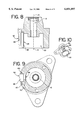
- FIG. 6 is a reverse cross-sectional view of the solenoid of the present invention depicted in FIG. 4.
- FIG. 7 is a top cut-away view of the positional sensor portion of the solenoid of the present invention.
- FIG. 8 is a cross-sectional side view of a portion of one housing of the solenoid of the present invention.
- FIG. 9 is a cross-sectional top view of the portion of the housing of the solenoid of the present invention depicted in FIG. 8.
- FIG. 10 is a perspective view of the portion of the housing of the solenoid of the present invention depicted in FIG. 8.
- FIG. 11 is a cross-sectional side view of a portion of another housing of the solenoid of the present invention.
- FIG. 12 is a cross-sectional top view of the portion of the housing of the solenoid of the present invention depicted in FIG. 11.
- FIG. 13 is a perspective view of the portion of the housing of the solenoid of the present invention depicted in FIG. 11.
- FIG. 14 is a front view of a cover plate of the housing of the solenoid of the present invention.
- FIG. 15 is a cross-sectional side view of one collar of the solenoid of the present invention.
- FIG. 16 is a cross-sectional side view of another collar of the solenoid of the present invention.
- FIGS. 1, 2, and 5 A positional electric solenoid 2, 2' with integral position feedback as shown in the attached figures.
- the solenoid has a housing 4 with a first or upper end 6 and a second or lower end 8.
- the solenoid also includes an actuator 9, as will be more fully described below.
- the actuator 9 extends from a housing 4 at the second end 8 of the housing 4.
- FIGS. 3, 4, and 6 show a second embodiment of a solenoid 2' of the present invention with one significant difference from the first embodiment being that the actuator 9 extends from the first end 6 of the housing 4 in the second embodiment. Both of these, and other, embodiments will be described in further detail below.
- the housing 4 has a housing bore 10 with a central axis 14.
- the central axis 14 extends along a line which runs through center of the housing bore 10.
- the housing bore 10 has a first end bore portion 18, a second end bore portion 20, and a central bore portion 22.
- the first end bore portion 18 opens at an opening 24 in the housing 4 at the first end 6 of the housing 4.
- the actuator 9 is sized to movably slide within the housing bore 10, along the central axis 14, within tubular bushings 28 mounted within the housing bore 10.
- a plunger 30 is provided within the central bore portion 22, and is connected to the actuator 9. The plunger 30 axial moves with the actuator 9 within the housing bore 10. As will more fully described below, the plunger 30 and actuator 9 can tend to slightly rotate.
- the solenoid 2, 2' also has an induction creating portion 32 within the housing 4 toward the second end 8 of the housing 4.
- This induction creating portion 32 typically is made from a coil winding (not shown) through which current is introduced.
- the coil winding is attached to leads 110 which provide the current for the solenoid 2, 2' actuation.
- the induction creating portion 32 will cause the plunger 30 and actuator 9 to move through the bore 10 along the central axis 14 either toward the first end 6 or second end 8 of the housing 4.
- the induction creating portion 32 has a cylindrical shape which is concentric with the central axis 14 of the housing 4.
- the induction creating portion 32 shown in the figures has an upwardly conical region 34
- the plunger 30 is manufactured in a manner, including design and choice of materials which cause the plunger to be affected by the induction created by the solenoid coil windings.
- the plunger 30 can also be considered as an induction affected portion.
- the induction affected portion 30 shown in the figures has a downwardly conical region 36 which generally matches with the upwardly conical region 34 of the induction creating portion 32.
- the solenoid 2, 2' also has a biasing member 40.
- the biasing member 40 shown in the figures is a spring.
- the spring 40 has a first end 42 and a second end 44.
- the first end 42 of the spring 40 is disposed adjacent to a collar 60 and engages with the collar 60.
- Various different collars 60 can be used with the present invention, as are depicted in 15 and 16.
- the second end 44 of the spring 40 is disposed adjacent to and engages with the induction creating portion 32
- the biasing member or spring 40 cooperates with and biases the collar 60 (a part of the plunger 30) and the plunger 16 along with the actuator 9 to a neutral position, as shown in the figures.
- the plunger 30 is forced in a direction along the central axis 14, depending on the direction of the current.
- the plunger 30, and its collar 60 is attached to the actuator 9 with rings 70 that engage notches 72 in the actuator 9, for movement of the plunger 30 (and collar 60) with the actuator 9.
- the collar 60 has an upper lip 62 and a lower lip 64 which form a groove 66.
- the groove 66 can be continuous, and is shown in that manner in the figures based on the upper and lower lips 62, 64 also being continuous.
- the groove 66 can also be formed from non-continuous upper and lower lips 62, 64 or notches as one of ordinary skill in the art would understand from this specification.
- the groove 66 creates a groove plane which is generally perpendicular to the central axis 14 in the figures.
- the biasing member 40 contacts the lower lip 64 of the collar 60 for biasing the collar 60, the plunger 30, and the actuator 9 in a direction along the central axis 14.
- the solenoid 2, 2' also has a position feedback reference or indicator 80.
- the indicator 80 in conjunction with other elements, acts as a potentiometer.
- the indicator 80 has a main portion 82, a protrusion 84 extending from the main portion 82, and an arm 86 extending from the main portion 82 in a direction generally opposed to direction of the protrusion 84.
- the arm 86 includes a wiper 88 which extends further in the direction generally opposed to the direction of the protrusion 84.
- the indicator 80 is moveably fitted with the collar 60 for movement with the collar 60.
- the protrusion 84 of the indicator 80 fits into the groove 66 of the collar 60 between the upper and lower lips 62, 64 of the collar 60.
- the indicator 80 moves with collar 60 through this fitting.
- the plunger 30 and collar 60 can tend to rotate around the central axis 14 in addition to the movement along the central axis.
- the protrusion 84 of the indicator 80 can slide within the groove 66, which prevents any wear which would otherwise occur from a more rigid connection.
- the housing 4 of the solenoid 2, 2' also has a channel or recess 90, within the first end 6 of the housing 4.
- the channel 90 includes a first channel or recessed region 92 adjacent the central region of 22 of the bore 10, and a second channel or recessed region 94 adjacent the first channel region 92 and adjacent the exterior of the housing 4.
- the first channel region 92 has a channel length which creates an indicator or indication path, which are both generally parallel to the central axis 14.
- the housing 4 also has an aperture along at least a part of the channel length between the first channel region 92 and the central bore 22.
- the second channel region 94 also has a channel length.
- the first channel region 92 and the second channel region 94 each also have a channel width.
- the channel length and width of the second channel region 94 are each slightly greater than the channel length and width of the first channel region 92, respectively. This slightly greater channel length and width of the second channel region 94 creates an abutment 100.
- the solenoid 2, 2' also has an indication receiver 102 located adjacent the indicator 80 and the indicator path for generating a signal that is representative of the position of the indicator 80 and the position of the actuator 9.
- the indicator 80 is positioned within the first channel region 92 to slide along the length of the first channel region 92, and along the indicator path, when the collar 60 moves along the central axis 14.
- the protrusion 84 of the indicator 80 protrudes through the aperture 96 of the channel 90 and through to the central region 22 of the bore 10. As described above, the protrusion 84 is fitted in the groove 66 of the collar 60 for movement with the collar 60, and thus movement with the actuator 9.
- the indication receiver 102 is positioned within the second channel region 94.
- the indication receiver 102 has edges which abut the abutment 100 of the second channel region 102 when the indication receiver 102 is inserted into the second channel region 94.
- at least one positioner 104 (two of them are shown in the some of the figures) is used temporarily fix the indication receiver 102 in place, abutting the abutment 100.
- the positioner 104 can be a ring, a clamp, a clip or some other mechanism which temporarily holds the indication receiver in place.
- a locking material 106 is placed within the second channel region 94. The locking material 106 surrounds the backside of the indication receiver 102 and contacts the abutment 100, for permanently fixing or locking the indication receiver 102 in place.
- the indicator 80 has a wiper 88 that is a part of the arm 86 extending from the main portion 82.
- the wiper 88 contacts the indication receiver 102 and causes a signal that is representative of the position of the actuator 9 to be generated.
- the indicator 80 has a main portion 82 which is moves within the first channel region 92 along the indicator path.
- the indication receiver 102 can be a resistance strip to obtain a reference signal designating the position of actuator 9.
- Position wires 112 are connected to the indication receiver 102 for carrying the signal that is representative of the position of the indicator 80 and the position of the actuator 9. Based on the actual value of the reference signal and the desired value of the reference signal, which can be measured through the 112 position wires, the amount of current directed through the coils of the solenoid can be controlled to obtain the desired position of the actuator 9.
- the present invention also includes a method of manufacturing the solenoid 2, 2'.
- the method is directed to the above described solenoid which has an actuator 9, an indicator 80 having an indicator path and being operatively connected to the actuator 9 for movement therewith.
- the solenoid 2, 2' also has an indication receiver 102 located adjacent the indicator and the indicator path for generating a signal that is representative of the position of the position of the actuator 9.
- the method includes aligning the indication receiver or strip 102 within the recess 90, and temporarily holding the indication receiver 102 in place with the positioner 104.
- the positioner 104 can be a ring, a clip, a clamp, or some other device which keeps the indication receiver 102 in place, but which also allows the indication receiver to be moved for calibration.
- the recess 90 also has notches 120 which can be used in conjunction with the positioner 104 to hold the indication receiver 102 in place.
- FIG. 7 depicts the positioner 104 having ends 105 which are bent toward the exterior of the housing and into the notches 120. This bending of the positioner 104 shown into the notches 120 places pressure on the indication receiver 102 by the positioner 104.
- FIG. 3 also shows the positioners 104 before insertion.
- the method also includes calibrating the signal, provided on the position wires 112, that is representative of the position of the actuator 9 with the actual position of the actuator 9.
- calibrating the signal provided on the position wires 112 that is representative of the position of the actuator 9 with the actual position of the actuator 9.
- a determination is made as to whether the indication receiver 102 needs to be repositioned.
- the positioner 104 does not need to be removed to reposition the indication receiver 102, and the positioner 104 does not place too much pressure on the indication receiver 102 so as to prevent the indication receiver 102 from sliding beneath the positioner 104.
- the indication receiver 102 is permanently locked in place with a locking material 106. This is performed by filling the recess 90 with a liquid compound which hardens after filling. Several compounds or filler materials can be used, as one of ordinary skill in the art would understand. The material 106 will then permanently lock the indication receiver in place.
- a cover 130 is used to cover the recess 90.
- the cover 130 includes holes 132 for receiving the position wires 112, which are attached to the indication receiver 102.
- the position wires 112 are connected to devices and apparatus (not shown) which are used for calibrating and determining the position of the actuator 9, as would be understood with reference to this specification and the knowledge of ordinary skill in the art.
- the cover 130 in FIG. 14 also has through passages through which the locking material 106 can be filled into the recess 90.
- the holes 132 could be instead connectors on one side of the cover 130 connect to the indication receiver 102, and on the other side are adapted to connect to wires.
Abstract
Description
Claims (36)
Priority Applications (1)
| Application Number | Priority Date | Filing Date | Title |
|---|---|---|---|
| US09/305,496 US6051897A (en) | 1999-05-05 | 1999-05-05 | Solenoid actuator with positional feedback |
Applications Claiming Priority (1)
| Application Number | Priority Date | Filing Date | Title |
|---|---|---|---|
| US09/305,496 US6051897A (en) | 1999-05-05 | 1999-05-05 | Solenoid actuator with positional feedback |
Publications (1)
| Publication Number | Publication Date |
|---|---|
| US6051897A true US6051897A (en) | 2000-04-18 |
Family
ID=23181045
Family Applications (1)
| Application Number | Title | Priority Date | Filing Date |
|---|---|---|---|
| US09/305,496 Expired - Fee Related US6051897A (en) | 1999-05-05 | 1999-05-05 | Solenoid actuator with positional feedback |
Country Status (1)
| Country | Link |
|---|---|
| US (1) | US6051897A (en) |
Cited By (20)
| Publication number | Priority date | Publication date | Assignee | Title |
|---|---|---|---|---|
| US6417759B2 (en) * | 2000-06-30 | 2002-07-09 | Alps Electric Co., Ltd. | Exhaust gas recirculation sensor |
| US6648979B2 (en) | 2001-01-24 | 2003-11-18 | International Business Machines Corporation | Apparatus and method for wafer cleaning |
| US20050024174A1 (en) * | 2003-08-01 | 2005-02-03 | Kolb Richard P. | Single coil solenoid having a permanent magnet with bi-directional assist |
| US20050029479A1 (en) * | 2003-08-08 | 2005-02-10 | Alps Electric Co., Ltd. | EGR sensor with drainage mechanism |
| US6876896B1 (en) | 1999-04-26 | 2005-04-05 | Ab Tetrapak | Variable motion system and method |
| US20070267922A1 (en) * | 2004-11-11 | 2007-11-22 | Masahiko Uni | Actuator |
| US20140216196A1 (en) * | 2013-02-06 | 2014-08-07 | Kia Motors Corporation | Non-contact type shift lock apparatus |
| US20150380194A1 (en) * | 2014-06-30 | 2015-12-31 | Lsis Co., Ltd. | Relay |
| US10020720B2 (en) | 2014-08-18 | 2018-07-10 | Eddy Current Limited Partnership | Latching devices |
| US10110089B2 (en) | 2014-08-18 | 2018-10-23 | Eddy Current Limited Partnership | Tuning of a kinematic relationship between members |
| US10300397B2 (en) | 2013-12-16 | 2019-05-28 | Eddy Current Limited Partnership | Assembly to control or govern relative speed of movement between parts |
| US10498210B2 (en) | 2014-08-18 | 2019-12-03 | Eddy Current Limited Partnership | Tuning of a kinematic relationship between members |
| US10532662B2 (en) | 2014-08-20 | 2020-01-14 | TruBlue LLC | Eddy current braking device for rotary systems |
| US10693360B2 (en) | 2014-12-04 | 2020-06-23 | Eddy Current Limited Partnership | Transmissions incorporating eddy current braking |
| US10774887B2 (en) | 2014-12-04 | 2020-09-15 | Eddy Current Limited Partnership | Latch activation between members |
| US10940339B2 (en) | 2014-12-04 | 2021-03-09 | Eddy Current Limited Partnership | Energy absorbing apparatus |
| US10953848B2 (en) | 2015-12-18 | 2021-03-23 | Eddy Current Limited Partnership | Variable behavior control mechanism for a motive system |
| US11050336B2 (en) | 2014-12-04 | 2021-06-29 | Eddy Current Limited Partnership | Methods of altering eddy current interactions |
| US11114930B2 (en) | 2014-12-04 | 2021-09-07 | Eddy Current Limited Partnership | Eddy current brake configurations |
| US11123580B2 (en) | 2009-03-10 | 2021-09-21 | Eddy Current Limited Partnership | Line dispensing device with Eddy current braking for use with climbing and evacuation |
Citations (21)
| Publication number | Priority date | Publication date | Assignee | Title |
|---|---|---|---|---|
| US2617050A (en) * | 1950-11-10 | 1952-11-04 | Mcgraw Electric Co | Electromagnetic control means |
| US3260870A (en) * | 1962-12-28 | 1966-07-12 | Ibm | Magnetic detent mechanism |
| US3433983A (en) * | 1966-11-14 | 1969-03-18 | United Aircraft Corp | Electromagnetic actuator |
| US3531666A (en) * | 1968-03-18 | 1970-09-29 | Kirsch Co | Linear induction motor actuator |
| US3883839A (en) * | 1973-10-29 | 1975-05-13 | Barber Colman Co | Positioning device |
| US4479107A (en) * | 1982-11-24 | 1984-10-23 | Cts Corporation | Precision linear potentiometer sensor |
| US4557355A (en) * | 1980-03-18 | 1985-12-10 | Richard Wilke | System for controlling an electromechanically reciprocable load |
| US4579146A (en) * | 1984-08-30 | 1986-04-01 | Nippondenso Co., Ltd. | Three-port solenoid-operated valve |
| US4623868A (en) * | 1984-01-10 | 1986-11-18 | Crystalate Electronics Limited | Variable electrical resistance device |
| US4635683A (en) * | 1985-10-03 | 1987-01-13 | Ford Motor Company | Variable force solenoid |
| US5031934A (en) * | 1990-03-30 | 1991-07-16 | Ford Motor Company | Vehicular suspension position sensor and method of calibration |
| US5072206A (en) * | 1988-11-08 | 1991-12-10 | Nippon Seiko Kabushiki Kaisha | Linear-movement potentiometer |
| US5103172A (en) * | 1989-04-08 | 1992-04-07 | Festo Kg | Piston and cylinder device with fixed conductive guide on periphery of cylinder |
| US5224410A (en) * | 1989-12-02 | 1993-07-06 | Graichen Kai Michael | Power booster with vacuum supply passage in position sensor housing |
| US5252938A (en) * | 1991-02-27 | 1993-10-12 | Lucas Industries Public Limited Company | Solenoid with armature biased towards the rest position with two springs |
| US5698910A (en) * | 1995-12-22 | 1997-12-16 | Eastman Kodak Company | Electromagnetic actuator with position sensor |
| US5939804A (en) * | 1997-02-10 | 1999-08-17 | Matsushita Electric Industrial Co., Ltd. | Linear actuator and optical equipment using the same |
| US5949161A (en) * | 1996-11-11 | 1999-09-07 | Minolta Co., Ltd. | Linear drive device |
| US5952743A (en) * | 1995-08-29 | 1999-09-14 | Sidey; Roger Charles Hey | Electric motor |
| US5959382A (en) * | 1995-10-13 | 1999-09-28 | Milli Sensor Systems And Actuators, Inc. | Magnetic actuator and position control system |
| US5965963A (en) * | 1998-02-26 | 1999-10-12 | Anorad Corporation | Linear motor with a plurality of stages independently movable on the same path |
-
1999
- 1999-05-05 US US09/305,496 patent/US6051897A/en not_active Expired - Fee Related
Patent Citations (21)
| Publication number | Priority date | Publication date | Assignee | Title |
|---|---|---|---|---|
| US2617050A (en) * | 1950-11-10 | 1952-11-04 | Mcgraw Electric Co | Electromagnetic control means |
| US3260870A (en) * | 1962-12-28 | 1966-07-12 | Ibm | Magnetic detent mechanism |
| US3433983A (en) * | 1966-11-14 | 1969-03-18 | United Aircraft Corp | Electromagnetic actuator |
| US3531666A (en) * | 1968-03-18 | 1970-09-29 | Kirsch Co | Linear induction motor actuator |
| US3883839A (en) * | 1973-10-29 | 1975-05-13 | Barber Colman Co | Positioning device |
| US4557355A (en) * | 1980-03-18 | 1985-12-10 | Richard Wilke | System for controlling an electromechanically reciprocable load |
| US4479107A (en) * | 1982-11-24 | 1984-10-23 | Cts Corporation | Precision linear potentiometer sensor |
| US4623868A (en) * | 1984-01-10 | 1986-11-18 | Crystalate Electronics Limited | Variable electrical resistance device |
| US4579146A (en) * | 1984-08-30 | 1986-04-01 | Nippondenso Co., Ltd. | Three-port solenoid-operated valve |
| US4635683A (en) * | 1985-10-03 | 1987-01-13 | Ford Motor Company | Variable force solenoid |
| US5072206A (en) * | 1988-11-08 | 1991-12-10 | Nippon Seiko Kabushiki Kaisha | Linear-movement potentiometer |
| US5103172A (en) * | 1989-04-08 | 1992-04-07 | Festo Kg | Piston and cylinder device with fixed conductive guide on periphery of cylinder |
| US5224410A (en) * | 1989-12-02 | 1993-07-06 | Graichen Kai Michael | Power booster with vacuum supply passage in position sensor housing |
| US5031934A (en) * | 1990-03-30 | 1991-07-16 | Ford Motor Company | Vehicular suspension position sensor and method of calibration |
| US5252938A (en) * | 1991-02-27 | 1993-10-12 | Lucas Industries Public Limited Company | Solenoid with armature biased towards the rest position with two springs |
| US5952743A (en) * | 1995-08-29 | 1999-09-14 | Sidey; Roger Charles Hey | Electric motor |
| US5959382A (en) * | 1995-10-13 | 1999-09-28 | Milli Sensor Systems And Actuators, Inc. | Magnetic actuator and position control system |
| US5698910A (en) * | 1995-12-22 | 1997-12-16 | Eastman Kodak Company | Electromagnetic actuator with position sensor |
| US5949161A (en) * | 1996-11-11 | 1999-09-07 | Minolta Co., Ltd. | Linear drive device |
| US5939804A (en) * | 1997-02-10 | 1999-08-17 | Matsushita Electric Industrial Co., Ltd. | Linear actuator and optical equipment using the same |
| US5965963A (en) * | 1998-02-26 | 1999-10-12 | Anorad Corporation | Linear motor with a plurality of stages independently movable on the same path |
Cited By (38)
| Publication number | Priority date | Publication date | Assignee | Title |
|---|---|---|---|---|
| US6876896B1 (en) | 1999-04-26 | 2005-04-05 | Ab Tetrapak | Variable motion system and method |
| US6417759B2 (en) * | 2000-06-30 | 2002-07-09 | Alps Electric Co., Ltd. | Exhaust gas recirculation sensor |
| US6648979B2 (en) | 2001-01-24 | 2003-11-18 | International Business Machines Corporation | Apparatus and method for wafer cleaning |
| US8274348B2 (en) | 2003-08-01 | 2012-09-25 | Woodward, Inc. | Single coil solenoid having a permanent magnet with bi-directional assist |
| US20050024174A1 (en) * | 2003-08-01 | 2005-02-03 | Kolb Richard P. | Single coil solenoid having a permanent magnet with bi-directional assist |
| US20050029479A1 (en) * | 2003-08-08 | 2005-02-10 | Alps Electric Co., Ltd. | EGR sensor with drainage mechanism |
| US6953031B2 (en) * | 2003-08-08 | 2005-10-11 | Alps Electric Co., Ltd. | EGR sensor with drainage mechanism |
| US20070267922A1 (en) * | 2004-11-11 | 2007-11-22 | Masahiko Uni | Actuator |
| US11123580B2 (en) | 2009-03-10 | 2021-09-21 | Eddy Current Limited Partnership | Line dispensing device with Eddy current braking for use with climbing and evacuation |
| US20140216196A1 (en) * | 2013-02-06 | 2014-08-07 | Kia Motors Corporation | Non-contact type shift lock apparatus |
| US10603596B2 (en) | 2013-12-16 | 2020-03-31 | Eddy Current Limited Partnership | Assembly to control or govern relative speed of movement between parts |
| US11628373B2 (en) | 2013-12-16 | 2023-04-18 | Eddy Current Limited Partnership | Assembly to control or govern relative speed of movement between parts |
| US11266917B2 (en) | 2013-12-16 | 2022-03-08 | Eddy Current Limited Partnership | Assembly to control or govern relative speed of movement between parts |
| US10300397B2 (en) | 2013-12-16 | 2019-05-28 | Eddy Current Limited Partnership | Assembly to control or govern relative speed of movement between parts |
| US20150380194A1 (en) * | 2014-06-30 | 2015-12-31 | Lsis Co., Ltd. | Relay |
| US9673010B2 (en) * | 2014-06-30 | 2017-06-06 | Lsis Co., Ltd. | Relay |
| US11437903B2 (en) | 2014-08-18 | 2022-09-06 | Eddy Current Limited Partnership | Latching devices |
| US11316404B2 (en) | 2014-08-18 | 2022-04-26 | Eddy Current Limited Partnership | Tuning of a kinematic relationship between members |
| US10110089B2 (en) | 2014-08-18 | 2018-10-23 | Eddy Current Limited Partnership | Tuning of a kinematic relationship between members |
| US11735992B2 (en) | 2014-08-18 | 2023-08-22 | Eddy Current Limited Partnership | Tuning of a kinematic relationship between members |
| US10873242B2 (en) | 2014-08-18 | 2020-12-22 | Eddy Current Limited Partnership | Tuning of a kinematic relationship between members |
| US11632016B2 (en) | 2014-08-18 | 2023-04-18 | Eddy Current Limited Partnership | Tuning of a kinematic relationship between members |
| US10594200B2 (en) | 2014-08-18 | 2020-03-17 | Eddy Current Limited Partnership | Latching devices |
| US10971988B2 (en) | 2014-08-18 | 2021-04-06 | Eddy Current Limited Partnership | Latching devices |
| US10020720B2 (en) | 2014-08-18 | 2018-07-10 | Eddy Current Limited Partnership | Latching devices |
| US11515776B2 (en) | 2014-08-18 | 2022-11-29 | Eddy Current Limited Partnership | Tuning of a kinematic relationship between members |
| US10498210B2 (en) | 2014-08-18 | 2019-12-03 | Eddy Current Limited Partnership | Tuning of a kinematic relationship between members |
| US10532662B2 (en) | 2014-08-20 | 2020-01-14 | TruBlue LLC | Eddy current braking device for rotary systems |
| US10693360B2 (en) | 2014-12-04 | 2020-06-23 | Eddy Current Limited Partnership | Transmissions incorporating eddy current braking |
| US11009089B2 (en) | 2014-12-04 | 2021-05-18 | Eddy Current Limited Partnership | Latch activation between members |
| US11499596B2 (en) | 2014-12-04 | 2022-11-15 | Eddy Current Limited Partnership | Latch activation between members |
| US11050336B2 (en) | 2014-12-04 | 2021-06-29 | Eddy Current Limited Partnership | Methods of altering eddy current interactions |
| US10940339B2 (en) | 2014-12-04 | 2021-03-09 | Eddy Current Limited Partnership | Energy absorbing apparatus |
| US10774887B2 (en) | 2014-12-04 | 2020-09-15 | Eddy Current Limited Partnership | Latch activation between members |
| US11777391B2 (en) | 2014-12-04 | 2023-10-03 | Eddy Current Limited Partnership | Methods of altering eddy current interactions |
| US11114930B2 (en) | 2014-12-04 | 2021-09-07 | Eddy Current Limited Partnership | Eddy current brake configurations |
| US11878651B2 (en) | 2015-12-18 | 2024-01-23 | Eddy Current Limited Partnership | Variable behavior control mechanism for a motive system |
| US10953848B2 (en) | 2015-12-18 | 2021-03-23 | Eddy Current Limited Partnership | Variable behavior control mechanism for a motive system |
Similar Documents
| Publication | Publication Date | Title |
|---|---|---|
| US6051897A (en) | Solenoid actuator with positional feedback | |
| US9846179B2 (en) | Electrical current transducer with electrostatic shield | |
| EP0844487B1 (en) | Magnetic sensor | |
| JP5579757B2 (en) | Current sensor | |
| US4313590A (en) | Solenoid valve for controlling flow of fluid | |
| US7830137B2 (en) | Position detecting sensor | |
| US5010298A (en) | Variable inductance displacement measuring device with slidable metal sleeve and ferrite bead core | |
| WO2006076968A1 (en) | A sensor | |
| CA1331785C (en) | Current detection device and core for detection of magnetic flux | |
| JPH0580124B2 (en) | ||
| US4748405A (en) | Current sensor arrangement | |
| JP3930057B2 (en) | Displacement measurement system for solenoid coil | |
| US20200072688A1 (en) | Sensor device | |
| US6442011B1 (en) | Flux concentration adjustment mechanism and method for hall effect sensors and circuit breaker using same | |
| JP2004170416A (en) | Measuring probe for measuring instrument especially for measuring thin-layer thickness | |
| US4899577A (en) | Device for a hardness measuring instrument | |
| US6140898A (en) | Inhibitor switch having magnetic contact portion | |
| US6404184B1 (en) | Simplified low backlash LVDT coupling | |
| EP3620754A1 (en) | A magnet holder and stroke sensor with the magnet holder | |
| US4121185A (en) | Linear position sensor | |
| GB2054970A (en) | Combined valve adjustment units | |
| US11821776B2 (en) | Mass flow sensor assembly and method of manufacturing a mass flow sensor assembly | |
| US6144272A (en) | Inhibitor switch having contact sections formed with magnetic sensors and permanent magnets | |
| AU5670700A (en) | Displacement measuring device | |
| USRE31062E (en) | Limited-rotation motor with integral displacement transducer |
Legal Events
| Date | Code | Title | Description |
|---|---|---|---|
| AS | Assignment |
Owner name: SYNCHRO-START PRODUCTS, INC., ILLINOIS Free format text: ASSIGNMENT OF ASSIGNORS INTEREST;ASSIGNORS:GLOGOVSKY, RICHARD S.;CODE, KEVIN C.;WISSLER, THOMAS;AND OTHERS;REEL/FRAME:010207/0038;SIGNING DATES FROM 19990629 TO 19990813 |
|
| AS | Assignment |
Owner name: JPMORGAN CHASE BANK, AS ADMINISTRATIVE AGENT, NEW Free format text: ASSIGNMENT OF ASSIGNORS INTEREST;ASSIGNOR:KNOWLES ELECTRONICS, INC.;REEL/FRAME:013727/0410 Effective date: 19990630 |
|
| REMI | Maintenance fee reminder mailed | ||
| FEPP | Fee payment procedure |
Free format text: PAYOR NUMBER ASSIGNED (ORIGINAL EVENT CODE: ASPN); ENTITY STATUS OF PATENT OWNER: LARGE ENTITY |
|
| FPAY | Fee payment |
Year of fee payment: 4 |
|
| SULP | Surcharge for late payment | ||
| AS | Assignment |
Owner name: WOODWARD GOVERNOR COMPANY, COLORADO Free format text: ASSIGNMENT OF ASSIGNORS INTEREST;ASSIGNOR:SYNCHRO-START PRODUCTS, INC.;REEL/FRAME:015312/0613 Effective date: 20040505 |
|
| FPAY | Fee payment |
Year of fee payment: 8 |
|
| AS | Assignment |
Owner name: KNOWLES ELECTRONICS HOLDINGS, INC., ILLINOIS Free format text: RELEASE BY SECURED PARTY;ASSIGNOR:JP MORGAN CHASE BANK N.A.;REEL/FRAME:023330/0290 Effective date: 20050927 |
|
| REMI | Maintenance fee reminder mailed | ||
| LAPS | Lapse for failure to pay maintenance fees | ||
| STCH | Information on status: patent discontinuation |
Free format text: PATENT EXPIRED DUE TO NONPAYMENT OF MAINTENANCE FEES UNDER 37 CFR 1.362 |
|
| FP | Lapsed due to failure to pay maintenance fee |
Effective date: 20120418 |