US6051002A - Stent crimping device and method of use - Google Patents
Stent crimping device and method of use Download PDFInfo
- Publication number
- US6051002A US6051002A US09/169,270 US16927098A US6051002A US 6051002 A US6051002 A US 6051002A US 16927098 A US16927098 A US 16927098A US 6051002 A US6051002 A US 6051002A
- Authority
- US
- United States
- Prior art keywords
- stent
- crimping
- handle
- loop
- handle member
- Prior art date
- Legal status (The legal status is an assumption and is not a legal conclusion. Google has not performed a legal analysis and makes no representation as to the accuracy of the status listed.)
- Expired - Fee Related
Links
Images


Classifications
-
- A—HUMAN NECESSITIES
- A61—MEDICAL OR VETERINARY SCIENCE; HYGIENE
- A61F—FILTERS IMPLANTABLE INTO BLOOD VESSELS; PROSTHESES; DEVICES PROVIDING PATENCY TO, OR PREVENTING COLLAPSING OF, TUBULAR STRUCTURES OF THE BODY, e.g. STENTS; ORTHOPAEDIC, NURSING OR CONTRACEPTIVE DEVICES; FOMENTATION; TREATMENT OR PROTECTION OF EYES OR EARS; BANDAGES, DRESSINGS OR ABSORBENT PADS; FIRST-AID KITS
- A61F2/00—Filters implantable into blood vessels; Prostheses, i.e. artificial substitutes or replacements for parts of the body; Appliances for connecting them with the body; Devices providing patency to, or preventing collapsing of, tubular structures of the body, e.g. stents
- A61F2/95—Instruments specially adapted for placement or removal of stents or stent-grafts
- A61F2/958—Inflatable balloons for placing stents or stent-grafts
-
- A—HUMAN NECESSITIES
- A61—MEDICAL OR VETERINARY SCIENCE; HYGIENE
- A61F—FILTERS IMPLANTABLE INTO BLOOD VESSELS; PROSTHESES; DEVICES PROVIDING PATENCY TO, OR PREVENTING COLLAPSING OF, TUBULAR STRUCTURES OF THE BODY, e.g. STENTS; ORTHOPAEDIC, NURSING OR CONTRACEPTIVE DEVICES; FOMENTATION; TREATMENT OR PROTECTION OF EYES OR EARS; BANDAGES, DRESSINGS OR ABSORBENT PADS; FIRST-AID KITS
- A61F2/00—Filters implantable into blood vessels; Prostheses, i.e. artificial substitutes or replacements for parts of the body; Appliances for connecting them with the body; Devices providing patency to, or preventing collapsing of, tubular structures of the body, e.g. stents
- A61F2/95—Instruments specially adapted for placement or removal of stents or stent-grafts
- A61F2/9522—Means for mounting a stent or stent-graft onto or into a placement instrument
Definitions
- This invention relates to a stent crimping device of the type that will enable the user to uniformly and tightly crimp a stent onto the distal end of a catheter assembly, for example of the kind used in a typical percutaneous transluminal coronary angioplasty (PTCA) procedure or percutaneous transluminal angioplasty (PTA) procedure.
- PTCA percutaneous transluminal coronary angioplasty
- PTA percutaneous transluminal angioplasty
- a guiding catheter is percutaneously introduced into the cardiovascular system of a patient through the brachial or femoral arteries and advanced through the vasculature until the distal end is in the ostium.
- a guide wire and a dilatation catheter having a balloon on the distal end are introduced through the guiding catheter with the guide wire sliding within the dilatation catheter.
- the guide wire is first advanced out of the guiding catheter into the patient's coronary vasculature, and the dilatation catheter is advanced over the previously advanced guide wire until the dilatation balloon is properly positioned across the lesion.
- a flexible, expandable, preformed balloon is inflated to a predetermined size at relatively high pressures to radially compress the atherosclerotic plaque of the lesion against the inside of the artery wall and thereby dilate the lumen of the artery.
- the balloon is then deflated to a small profile, so that the dilatation catheter can be withdrawn from the patient's vasculature and blood flow resumed through the dilated artery. While this procedure is typical, it is not the only method used in angioplasty. Other methods for compressing plaque or removing it are known, such as atherectomies or use of plaque dissolving drugs.
- a restenosis of the artery may develop over several months, which may require another angioplasty procedure, a surgical bypass operation, or some method of repairing or strengthening the area.
- a physician can implant an intravascular prosthesis for maintaining vascular patency, typically called a stent.
- a stent is a device used to hold tissue in place in a vessel or to provide a support for a vessel to hold it open so that blood flows freely.
- stents A variety of devices are known in the art for use as stents, including expandable tubular members, in a variety of configurations, that are able to be crimped onto a balloon catheter, and expanded after being positioned intraluminally on the balloon catheter, and that retain their expanded form.
- the stent is loaded and crimped onto the balloon portion of the catheter, and advanced to a location inside the artery at the lesion.
- the stent is then expanded to a larger diameter, by the balloon portion of the catheter, to implant the stent in the artery at the lesion.
- Examples of stents and delivery catheters of the type described herein are disclosed in more detail in U.S. Pat. No. 5,102,417 (Palmaz); U.S. Pat. No. 5,569,295 (Lam); and U.S. Pat. No. 5,514,154 (Lau et al.).
- the stent may move or possibly slide off the catheter balloon portion in the coronary artery prior to expansion, and may block the flow of blood, requiring procedures to remove the stent.
- the stent In procedures where the stent is placed over the balloon portion of the catheter, the stent must be compressed or crimped onto the balloon portion to prevent the stent from sliding off the catheter when the catheter is advanced in the patient's vasculature. In the past this crimping was often done by hand, which does not provide optimum results due to the uneven force being applied, resulting in non-uniform crimps. In addition, it was difficult to judge when a uniform and reliable crimp had been applied. Though some tools, such as ordinary pliers, have been used to crimp the stent, these tools have not been entirely adequate in achieving an effective crimp. Moreover, an ineffectively crimped stent may result in an ineffectively expanded stent in the vessel or artery, which is undesirable.
- the invention is directed to a crimping tool and method of use for enabling effective crimping of a stent onto the balloon portion of a catheter in order to better secure a stent onto the catheter for low-profile delivery of the stent through the patient's vascular system.
- the present invention attempts to solve several problems associated with crimping stents onto balloon catheters.
- the stent crimping tool includes a pair of handles pivotally engaged such that a first handle member receives within it a second handle member.
- the invention further includes a cylindrical loop crimping member comprising a flexible sheet or film of material, such as a thin piece of Mylar material, in the form of a loop.
- the ends of the loop are attached respectively to the first handle and the second handle.
- An application of force on the handles causes the prospective ends of the cylindrical loop to move in opposite directions thereby providing a tension force which results in reducing the opening of the cylindrical loop.
- the invention further provides for mounting a stent on the balloon portion of a catheter, and positioning the stent and balloon portion of the catheter within the cylindrical loop. As the handles of the stent crimping tool are compressed, the ends of the cylindrical loop are pulled in opposite directions thereby reducing the size of the loop and tightly compressing the stent in a uniform manner on the balloon portion of the catheter.
- the cylindrical loop By releasing the handles, which are biased open, the cylindrical loop returns to its original size, thereby permitting the stent and balloon portion of the catheter to be removed from the cylindrical loop.
- the cylindrical loop is formed from a substantially non-stretchable plastic material having a high tensile strength and a low modulus.
- One of the handles of the stent crimping tool includes reference indicia relative to the other handle member so that the reference indicia correspond to the crimping diameter of the cylindrical loop. As the two handles are compressed one into the other, the reference indicia will indicate the size or diameter of the cylindrical loop, and thereby determine the ultimate travel and thus, the resultant crimped diameter of the stent onto the balloon portion of the catheter.
- FIG. 1 is a perspective view of an exemplary embodiment of the present invention, in which the pivotally-engaging member is pivoted into engagement with the receiving member.
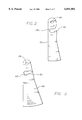
- FIG. 2 is a plan view of the first handle member of the crimping tool.
- FIG. 3 is a plan view depicting the second handle member of the crimping tool, which is configured for slidably engaging the first handle member of FIG. 2.
- FIG. 4 is a plan view depicting the first and second handle members pivotally engaged so that the cylindrical loop is positioned for receiving a stent for crimping onto the balloon portion of a catheter.
- FIG. 5 is a plan view depicting the second handle member squeezed into the first handle member thereby restricting the diameter of the cylindrical loop which provides the crimping force on the stent.
- FIGS. 6-9 are side elevational views depicting a series of crimping steps wherein the cylindrical loop gradually tightens onto the stent thereby crimping it onto the balloon portion of the catheter as the loop ends are moved in opposite directions.
- FIG. 10 is a perspective view of the cylindrical loop with the stent and the balloon portion of the catheter positioned within the loop.
- FIG. 11 is a plan view depicting one preferred embodiment of the cylindrical loop in an uncoiled and flattened configuration.
- FIGS. 12A-12C are perspective views depicting various embodiments of protective sheaths.
- the present invention provides for a crimping tool which uniformly and tightly crimps an expandable stent onto a catheter, such as a balloon catheter, so that the stent remains removably attached to the catheter until the stent and catheter are positioned in a body lumen.
- device 10 comprises crimping tool 20 for enabling effective crimping of an intravascular stent 11 onto the collapsed balloon portion 12 adjacent the distal end 13 of a balloon catheter assembly 14.
- crimping tool 20 is adapted to be held in the hand of the user, so as to enable stent 11 and catheter 14 to be supported in tool 20, and to enable the user to apply compressive force to tool 20 to crimp stent 11 on catheter 14.
- Crimping tool 20 includes first handle member 22, second handle member 24 pivotally movable into engagement with first handle member 22 in a generally pendulum-like movement, and pin 26 pivotally connecting the upper portions of first handle member 22 and second handle member 24.
- First handle member 22 and second handle member 24 are engageable and generally complementary and preferably somewhat triangular in shape to ergonomically fit the hand, and include slots 28 and 30 therein which are preferably somewhat arcuate-shaped.
- first handle member 22 is configured to receive second handle member 24.
- Crimping tool 20 further includes crimping member 32 which is disposed within slots 28,30 which is adapted to receive stent 11 mounted on balloon portion 12 of the catheter assembly 14.
- Crimping member 32 includes cylindrical loop 34 having first end 36 and second end 38. First end 36 of cylindrical loop 34 is attached to first attachment member 40 on first handle member 22. Second end 38 of cylindrical loop 34 is attached by second attachment member 42 to second handle member 24.
- First attachment member 40 and second attachment member 42 can be of any design which can removably attach first end 36 and second end 38 respectively to the first and second handle members.
- first attachment member 40 and second attachment member 42 can include a snap or jaw-like member which grips first end 36 and second end 38 of cylindrical loop 34. It is intended, for example, that cylindrical loop 34 be replaceable when it wears out.
- first end 36 of the cylindrical loop is attached to first attachment member 40 on first handle member 22 and second end 38 is attached by second attachment member 42 to second handle member 24.
- first and second attachment members can be of any design which can removably attach the first and second ends of the cylindrical loop to the handle members.
- apertures 44,46 are provided as convenient attachment means to correspond with a snap or jaw-like member on the handle members to help grip and removably attach first and second ends 36,38.
- a slot 48 is provided in the cylindrical loop to receive first end 36 to form the loop.
- Flanges 49 are provided to prevent the loop overtravel.
- the width 45 of the cylindrical loop should coincide with the length of the stent which typically is from about 6 mm to 30 mm.
- the width can be selected to accommodate either shorter or longer stents as necessary.
- width 45 is selected so that the full length of the stent is covered by the cylindrical loop since it generally is undesirable to crimp less than the entire stent length at one time.
- the cylindrical loop can be formed of any non-stretchable material, and preferably is formed of Mylar or a similar flexible, but non-stretchable plastic material.
- the crimping tool can be used repeatedly to crimp stents onto the balloon portion of catheters. Repeated use will result in the cylindrical loop wearing out, whereby it should be replaced.
- first attachment member 40 second attachment member 42 provide means for releasing the ends of the cylindrical loop and accepting ends of a replacement cylindrical loop for further use.
- an adhesive may be used to permanently attach first end 36 and second end 38 to the handle members, for use in those situations where the crimping tool 20 is designed for a single-use application, as will be described.
- Crimping tool 20 also is adapted for a single-use application, for example, by a cath lab physician or cath lab personnel. In that situation, crimping tool 20 can be discarded after the stent is crimped onto the balloon portion of the catheter. Further, first attachment member 40 and second attachment member 42 can be a permanent attachment, as opposed to a removable attachment to attach the ends of the cylindrical loop to the handle members.
- stent 11 is first positioned over balloon portion 12 by hand, and then catheter assembly 14 is moved within cylindrical loop 34 to receive the crimping procedure.
- FIGS. 6-10 depict loop 34 as having no or very little width, however, loop 34 should preferably have a width that approximates the length of the stent, which typically may be 20 mm or more as previously described for thc FIG. 11 embodiment.
- First handle member 22 and second handle member 24 are compressed together thereby moving ends 36, 38 in opposite directions as depicted in FIGS. 6-9. As the opening of cylindrical loop 34 becomes smaller, the loop tightens around stent 11 thereby crimping it onto the balloon portion of the catheter.
- Reference indicia 50 on second handle member 24 corresponds to the size or diameter of cylindrical loop 34.
- the crimping tool can easily determine the crimping force, and importantly, the crimped diameter of the stent on the balloon portion of the catheter.
- the reference indicia correspond to the final diameter, or crimped diameter of the stent, thereby taking the guesswork out of the crimping procedure as it relates to the amount of force applied to the stent and the final crimped diameter.
- the first and second handle members are biased open, such as by a coil spring or other biasing means, so that when the compressive force of the user's hand is released, the handles will move open and away from each other.
- cylindrical loop 34 has enough resiliency in the material that it naturally will open, allowing the crimped stent and balloon catheter assembly to be withdrawn.
- sheath 60 can be positioned over the stent, preferably prior to crimping the stent.
- the sheath can have various configurations such as those shown in FIGS. 12A-12C, and preferably has sufficient length and wall thickness to cover the stent and uniformly distribute the crimping forces applied to the stent by crimping tool 20. As the crimping tool applies force to the sheath, the force is evenly distributed over the sheath and hence to the stent.
- the sheath can be left on the stent after crimping and provide a cover to protect the stent in a safe manner until just before the stent is implanted in the patient.
- slots 61 are formed in the sheath so that strips 62 in between the slots cover specific portions of the stent to prevent fish scaling during the crimping process.
- Fish scaling which results from portions of the stent moving radially outwardly due to uneven crimping forces, can occur during the crimping process with some stent configurations.
- strips 62 are positioned over portions of the stent susceptible to fish scaling to counteract the effect and maintain a cylindrical geometry in the stent.
- the sheath can be formed from an elastic material known in the art and can have various thicknesses depending on the particular stent configuration. Slots 51 or other apertures 54 are formed in the sheath using a laser or by other means known in the art. The sheath is removed prior to implanting the stent in the patient.
- the present invention crimping tool 20 can be used in a manufacturing facility having a sterile environment to be used multiple times to crimp multiple stents on catheter assemblies. It is also contemplated that the crimping tool 20 will be used for single use applications by cath lab personnel, where a stent is crimped onto the balloon portion of a catheter, and the tool is then discarded, since there is no assurance that the tool can be sterilized after the single use application in the cath lab.
- the stent described is intended to be an intraluminal vascular prosthesis for use within a blood vessel, such as a saphenous vein, coronary artery, carotid artery, etc., and the balloon delivery catheter is of the same or similar to that used in therapeutic coronary angioplasty, it will be appreciated by those skilled in the art that modifications may be made to the present invention to allow the present invention to be used to crimp any type of stent onto any catheter.
- the present invention is not limited to stents that are deployed in a patient's vasculature, but has wide applications to loading any type of graft, prosthesis, liner or similar structure.
- the stent may be delivered and implemented not only into coronary arteries, but into any body lumen. Other modifications can be made to the present invention by those skilled in the art without departing from the scope thereof.
Abstract
Description
Claims (12)
Priority Applications (3)
| Application Number | Priority Date | Filing Date | Title |
|---|---|---|---|
| US09/169,270 US6051002A (en) | 1998-10-09 | 1998-10-09 | Stent crimping device and method of use |
| AU62860/99A AU6286099A (en) | 1998-10-09 | 1999-10-01 | Stent crimping device and method of use |
| PCT/US1999/023021 WO2000021464A1 (en) | 1998-10-09 | 1999-10-01 | Stent crimping device and method of use |
Applications Claiming Priority (1)
| Application Number | Priority Date | Filing Date | Title |
|---|---|---|---|
| US09/169,270 US6051002A (en) | 1998-10-09 | 1998-10-09 | Stent crimping device and method of use |
Publications (1)
| Publication Number | Publication Date |
|---|---|
| US6051002A true US6051002A (en) | 2000-04-18 |
Family
ID=22614940
Family Applications (1)
| Application Number | Title | Priority Date | Filing Date |
|---|---|---|---|
| US09/169,270 Expired - Fee Related US6051002A (en) | 1998-10-09 | 1998-10-09 | Stent crimping device and method of use |
Country Status (3)
| Country | Link |
|---|---|
| US (1) | US6051002A (en) |
| AU (1) | AU6286099A (en) |
| WO (1) | WO2000021464A1 (en) |
Cited By (46)
| Publication number | Priority date | Publication date | Assignee | Title |
|---|---|---|---|---|
| US6141855A (en) * | 1998-04-28 | 2000-11-07 | Advanced Cardiovascular Systems, Inc. | Stent crimping tool and method of use |
| US6309383B1 (en) * | 2000-01-20 | 2001-10-30 | Isostent, Inc. | Stent crimper apparatus with radiation shied |
| US20020138129A1 (en) * | 1999-01-22 | 2002-09-26 | Armstrong Joseph R. | Method of producing low profile stent and graft combination |
| US20020163104A1 (en) * | 2001-03-26 | 2002-11-07 | Tom Motsenbocker | Balloon folding technology |
| US6568235B1 (en) | 2000-08-10 | 2003-05-27 | Advanced Cardiovascular Systems, Inc. | Assembly for crimping an intraluminal device or measuring the radial strength of the intraluminal device and method of use |
| US6629350B2 (en) | 2000-06-08 | 2003-10-07 | Tom Motsenbocker | Stent crimping apparatus and method |
| US6640412B2 (en) | 2001-04-26 | 2003-11-04 | Endovascular Technologies, Inc. | Method for loading a stent using a collapsing machine |
| US6823576B2 (en) | 1999-09-22 | 2004-11-30 | Scimed Life Systems, Inc. | Method and apparatus for contracting, loading or crimping self-expanding and balloon expandable stent devices |
| US6878158B2 (en) | 2000-07-11 | 2005-04-12 | Sorin Biomedica Cardio S.P.A. | Process for coupling an angioplasty stent to a corresponding insertion element, and kit thus formed |
| US20050159802A1 (en) * | 2004-01-15 | 2005-07-21 | Icon Interventional Systems, Inc., An Ohio Corporation | Method for verifying position on an angioplasty balloon |
| US20050166389A1 (en) * | 2004-01-29 | 2005-08-04 | Scimed Life Systems, Inc. | Apparatuses for crimping and loading of intraluminal medical devices |
| US20050229670A1 (en) * | 2004-04-16 | 2005-10-20 | Scimed Life Systems, Inc. | Stent crimper |
| US20050234537A1 (en) * | 2004-04-16 | 2005-10-20 | Scimed Life Systems, Inc. | Stent crimper |
| US20060064152A1 (en) * | 2002-01-23 | 2006-03-23 | Boston Scientific Scimed, Inc. | Stent delivery system loading tool |
| US7112055B1 (en) | 2002-07-02 | 2006-09-26 | Endovascular Technologies, Inc. | Nitinol frame heating and setting mandrel |
| US20060224175A1 (en) * | 2005-03-29 | 2006-10-05 | Vrba Anthony C | Methods and apparatuses for disposition of a medical device onto an elongate medical device |
| US20060229712A1 (en) * | 2005-04-12 | 2006-10-12 | Advanced Cardiovascular Systems, Inc. | Method of stent mounting to form a balloon catheter having improved retention of a drug delivery stent |
| US20070288080A1 (en) * | 2006-06-07 | 2007-12-13 | Maccollum Michael W | Stent expanding device |
| US20070288034A1 (en) * | 2006-06-07 | 2007-12-13 | Maccollum Michael W | Stent Expanding device |
| US20080127707A1 (en) * | 2006-11-30 | 2008-06-05 | Abbott Laboratories | Stent crimping assembly and method |
| US7389670B1 (en) | 2004-07-26 | 2008-06-24 | Abbott Laboratories | Stent crimping system |
| US20080262603A1 (en) * | 2007-04-23 | 2008-10-23 | Sorin Biomedica Cardio | Prosthetic heart valve holder |
| EP2014257A1 (en) | 2007-07-12 | 2009-01-14 | Sorin Biomedica Cardio S.R.L. | Expandable prosthetic valve crimping device |
| US20090018570A1 (en) * | 2007-07-12 | 2009-01-15 | Sorin Biomedica Cardio S.R.L. | Expandable prosthetic valve crimping device |
| US20090131920A1 (en) * | 2007-11-16 | 2009-05-21 | Abbott Laboratories Vascular Enterprises Limited | Stent crimping apparatus |
| US20090259287A1 (en) * | 2008-04-09 | 2009-10-15 | Cook Incorporated | Loading apparatus and method for expandable intraluminal medical devices |
| US20100057182A1 (en) * | 2008-08-02 | 2010-03-04 | Kevin Pilz | Method and device for loading a stent applicator |
| US20100185207A1 (en) * | 2009-01-20 | 2010-07-22 | Abbott Laboratories Vascular Enterprises Limited | Stent crimping device |
| US20100249661A1 (en) * | 2009-03-19 | 2010-09-30 | Sorin Biomedica Cardio S.r.I | Universal Valve Annulus Sizing Device |
| US20100262043A1 (en) * | 2009-03-26 | 2010-10-14 | Sorin Group Usa, Inc. | Annuloplasty sizers for minimally invasive procedures |
| US8221112B2 (en) | 2005-04-12 | 2012-07-17 | Abbott Cardiovascular Systems, Inc. | Method for retaining a vascular stent on a catheter |
| US8562663B2 (en) | 2010-10-26 | 2013-10-22 | Medtronic Ventor Technologies Ltd. | Devices and methods for loading a prosthesis onto a delivery system |
| US9248017B2 (en) | 2010-05-21 | 2016-02-02 | Sorin Group Italia S.R.L. | Support device for valve prostheses and corresponding kit |
| US9289289B2 (en) | 2011-02-14 | 2016-03-22 | Sorin Group Italia S.R.L. | Sutureless anchoring device for cardiac valve prostheses |
| US9308569B2 (en) | 2013-02-01 | 2016-04-12 | Medtronic, Inc. | Devices and methods for crimping and loading a medical device into a delivery system |
| US9308346B2 (en) | 2013-02-01 | 2016-04-12 | Medtronic, Inc. | Devices and methods for crimping and loading a collapsible device into a delivery system |
| US9486313B2 (en) | 2005-02-10 | 2016-11-08 | Sorin Group Italia S.R.L. | Cardiac valve prosthesis |
| US9821091B2 (en) | 2006-06-06 | 2017-11-21 | Abbot Cardiovascular Systems Inc. | Methods of treatment of polymeric coatings for control of agent release rates |
| US9848981B2 (en) | 2007-10-12 | 2017-12-26 | Mayo Foundation For Medical Education And Research | Expandable valve prosthesis with sealing mechanism |
| US9867695B2 (en) | 2004-03-03 | 2018-01-16 | Sorin Group Italia S.R.L. | Minimally-invasive cardiac-valve prosthesis |
| US10010412B2 (en) | 2011-07-27 | 2018-07-03 | Edwards Lifesciences Corporation | Conical crimper |
| US10098733B2 (en) | 2008-12-23 | 2018-10-16 | Sorin Group Italia S.R.L. | Expandable prosthetic valve having anchoring appendages |
| US10716691B2 (en) | 2016-06-24 | 2020-07-21 | Edwards Lifesciences Corporation | Compact crimping device |
| US11504231B2 (en) | 2018-05-23 | 2022-11-22 | Corcym S.R.L. | Cardiac valve prosthesis |
| US11819406B2 (en) | 2018-05-23 | 2023-11-21 | Corcym S.R.L. | Loading system for an implantable prosthesis and related loading method |
| US11944559B2 (en) | 2020-08-31 | 2024-04-02 | Edwards Lifesciences Corporation | Systems and methods for crimping and device preparation |
Families Citing this family (16)
| Publication number | Priority date | Publication date | Assignee | Title |
|---|---|---|---|---|
| DE10046528A1 (en) * | 2000-08-09 | 2002-02-21 | Biotronik Mess & Therapieg | Method and device for crimping a stent |
| EP1179322A3 (en) | 2000-08-09 | 2004-02-25 | BIOTRONIK Mess- und Therapiegeräte GmbH & Co Ingenieurbüro Berlin | Stent crimping method and device |
| PL2338440T3 (en) * | 2004-11-02 | 2013-06-28 | Machine Solutions Inc | Stent sheathing technology |
| DE102005003632A1 (en) | 2005-01-20 | 2006-08-17 | Fraunhofer-Gesellschaft zur Förderung der angewandten Forschung e.V. | Catheter for the transvascular implantation of heart valve prostheses |
| US7896915B2 (en) | 2007-04-13 | 2011-03-01 | Jenavalve Technology, Inc. | Medical device for treating a heart valve insufficiency |
| WO2011104269A1 (en) | 2008-02-26 | 2011-09-01 | Jenavalve Technology Inc. | Stent for the positioning and anchoring of a valvular prosthesis in an implantation site in the heart of a patient |
| US9044318B2 (en) | 2008-02-26 | 2015-06-02 | Jenavalve Technology Gmbh | Stent for the positioning and anchoring of a valvular prosthesis |
| WO2010130789A1 (en) * | 2009-05-15 | 2010-11-18 | Jenavalve Technology Inc. | Device for compressing a stent as well as system and method for loading a stent into a medical delivery system |
| JP2013526388A (en) | 2010-05-25 | 2013-06-24 | イエナバルブ テクノロジー インク | Artificial heart valve, and transcatheter delivery prosthesis comprising an artificial heart valve and a stent |
| EP2486893B1 (en) | 2011-02-14 | 2017-07-05 | Sorin Group Italia S.r.l. | Sutureless anchoring device for cardiac valve prostheses |
| EP2768432A1 (en) | 2011-10-21 | 2014-08-27 | JenaValve Technology Inc. | Catheter system for introducing an expandable heart valve stent into the body of a patient, insertion system with a catheter system and medical device for treatment of a heart valve defect |
| US9878127B2 (en) | 2012-05-16 | 2018-01-30 | Jenavalve Technology, Inc. | Catheter delivery system for heart valve prosthesis |
| CN105491978A (en) | 2013-08-30 | 2016-04-13 | 耶拿阀门科技股份有限公司 | Radially collapsible frame for a prosthetic valve and method for manufacturing such a frame |
| US10709555B2 (en) | 2015-05-01 | 2020-07-14 | Jenavalve Technology, Inc. | Device and method with reduced pacemaker rate in heart valve replacement |
| EP3454795B1 (en) | 2016-05-13 | 2023-01-11 | JenaValve Technology, Inc. | Heart valve prosthesis delivery system for delivery of heart valve prosthesis with introducer sheath and loading system |
| CN110392557A (en) | 2017-01-27 | 2019-10-29 | 耶拿阀门科技股份有限公司 | Heart valve simulation |
Citations (20)
| Publication number | Priority date | Publication date | Assignee | Title |
|---|---|---|---|---|
| US696289A (en) * | 1901-07-26 | 1902-03-25 | Maryland Shoe Machinery Company | Machine for inserting protectors in heels and soles of shoes. |
| GB159065A (en) * | 1919-12-09 | 1921-02-24 | William Levi Secord | Improvements relating to machine and other vices and like work holding or setting appliances |
| US4468224A (en) * | 1982-01-28 | 1984-08-28 | Advanced Cardiovascular Systems, Inc. | System and method for catheter placement in blood vessels of a human patient |
| US4576142A (en) * | 1982-11-19 | 1986-03-18 | Peter Schiff | Percutaneous intra-aortic balloon and method for using same |
| US4644936A (en) * | 1982-11-19 | 1987-02-24 | Iabp | Percutaneous intra-aortic balloon and method for using same |
| US4681092A (en) * | 1985-05-21 | 1987-07-21 | Kontron Inc. | Balloon catheter wrapping apparatus |
| US4697573A (en) * | 1982-11-19 | 1987-10-06 | Iabp Corporation | Percutaneous intra-aortic balloon and method for using same |
| US4901707A (en) * | 1982-11-19 | 1990-02-20 | Iabp Corporation | Prepackaged intra-aortic balloon assembly with holder, and method of using same |
| US4907336A (en) * | 1987-03-13 | 1990-03-13 | Cook Incorporated | Method of making an endovascular stent and delivery system |
| US5189786A (en) * | 1990-11-13 | 1993-03-02 | Sumitomo Wiring Systems, Ltd. | Electrical cable stripping method and electrical cable loosening device |
| US5437083A (en) * | 1993-05-24 | 1995-08-01 | Advanced Cardiovascular Systems, Inc. | Stent-loading mechanism |
| US5626604A (en) * | 1995-12-05 | 1997-05-06 | Cordis Corporation | Hand held stent crimping device |
| US5653691A (en) * | 1996-04-25 | 1997-08-05 | Rupp; Garry Eugene | Thickened inner lumen for uniform stent expansion and method of making |
| US5672169A (en) * | 1996-04-10 | 1997-09-30 | Medtronic, Inc. | Stent mounting device |
| WO1998014120A1 (en) * | 1996-09-30 | 1998-04-09 | Medtronic Instent Israel Ltd. | Stent loading device for a balloon catheter |
| US5746764A (en) * | 1995-12-04 | 1998-05-05 | Atrion Medical Products, Inc. | Stent compression instrument |
| WO1998019633A1 (en) * | 1996-11-06 | 1998-05-14 | Percusurge, Inc. | Apparatus and method for loading a stent on a catheter |
| US5783227A (en) * | 1996-01-22 | 1998-07-21 | Cordis Corporation | Catheter balloon folding device |
| US5785715A (en) * | 1995-12-07 | 1998-07-28 | Schatz; Richard A. | Retrieval shuttle |
| US5836952A (en) * | 1996-08-21 | 1998-11-17 | Cordis Corporation | Hand-held stent crimper |
Family Cites Families (8)
| Publication number | Priority date | Publication date | Assignee | Title |
|---|---|---|---|---|
| US1966593A (en) * | 1933-06-05 | 1934-07-17 | Mathias Klein & Sons | Wire splicing tool |
| FR975797A (en) * | 1948-12-03 | 1951-03-09 | Auto-stop nutcracker | |
| US5102417A (en) | 1985-11-07 | 1992-04-07 | Expandable Grafts Partnership | Expandable intraluminal graft, and method and apparatus for implanting an expandable intraluminal graft |
| DE3727245A1 (en) * | 1987-08-15 | 1989-02-23 | Weitkowitz Elektro Gmbh | NOTCH PLIERS FOR PRESSING CORE SLEEVES, CABLE SHOES AND CONNECTORS ON ELECTRICAL LADDERS |
| CA2079417C (en) | 1991-10-28 | 2003-01-07 | Lilip Lau | Expandable stents and method of making same |
| JP2703510B2 (en) | 1993-12-28 | 1998-01-26 | アドヴァンスド カーディオヴァスキュラー システムズ インコーポレーテッド | Expandable stent and method of manufacturing the same |
| DE29714857U1 (en) * | 1997-08-20 | 1997-10-09 | Ziegerer Rainer | Device for deforming a grating-like, radially deformable pipe section |
| US6202272B1 (en) * | 1998-02-26 | 2001-03-20 | Advanced Cardiovascular Systems, Inc. | Hand-held stent crimping device |
-
1998
- 1998-10-09 US US09/169,270 patent/US6051002A/en not_active Expired - Fee Related
-
1999
- 1999-10-01 AU AU62860/99A patent/AU6286099A/en not_active Abandoned
- 1999-10-01 WO PCT/US1999/023021 patent/WO2000021464A1/en active Application Filing
Patent Citations (22)
| Publication number | Priority date | Publication date | Assignee | Title |
|---|---|---|---|---|
| US696289A (en) * | 1901-07-26 | 1902-03-25 | Maryland Shoe Machinery Company | Machine for inserting protectors in heels and soles of shoes. |
| GB159065A (en) * | 1919-12-09 | 1921-02-24 | William Levi Secord | Improvements relating to machine and other vices and like work holding or setting appliances |
| US4468224A (en) * | 1982-01-28 | 1984-08-28 | Advanced Cardiovascular Systems, Inc. | System and method for catheter placement in blood vessels of a human patient |
| US4576142A (en) * | 1982-11-19 | 1986-03-18 | Peter Schiff | Percutaneous intra-aortic balloon and method for using same |
| US4644936A (en) * | 1982-11-19 | 1987-02-24 | Iabp | Percutaneous intra-aortic balloon and method for using same |
| US4697573A (en) * | 1982-11-19 | 1987-10-06 | Iabp Corporation | Percutaneous intra-aortic balloon and method for using same |
| US4901707A (en) * | 1982-11-19 | 1990-02-20 | Iabp Corporation | Prepackaged intra-aortic balloon assembly with holder, and method of using same |
| US4681092A (en) * | 1985-05-21 | 1987-07-21 | Kontron Inc. | Balloon catheter wrapping apparatus |
| US4907336A (en) * | 1987-03-13 | 1990-03-13 | Cook Incorporated | Method of making an endovascular stent and delivery system |
| US5189786A (en) * | 1990-11-13 | 1993-03-02 | Sumitomo Wiring Systems, Ltd. | Electrical cable stripping method and electrical cable loosening device |
| US5437083A (en) * | 1993-05-24 | 1995-08-01 | Advanced Cardiovascular Systems, Inc. | Stent-loading mechanism |
| US5546646A (en) * | 1993-05-24 | 1996-08-20 | Advanced Cardiovascular Systems, Inc. | Method for mounting an intravascular stent on a catheter |
| US5738674A (en) * | 1993-05-24 | 1998-04-14 | Advanced Cardiovascular Systems, Inc. | Stent loading mechanism |
| US5746764A (en) * | 1995-12-04 | 1998-05-05 | Atrion Medical Products, Inc. | Stent compression instrument |
| US5626604A (en) * | 1995-12-05 | 1997-05-06 | Cordis Corporation | Hand held stent crimping device |
| US5785715A (en) * | 1995-12-07 | 1998-07-28 | Schatz; Richard A. | Retrieval shuttle |
| US5783227A (en) * | 1996-01-22 | 1998-07-21 | Cordis Corporation | Catheter balloon folding device |
| US5672169A (en) * | 1996-04-10 | 1997-09-30 | Medtronic, Inc. | Stent mounting device |
| US5653691A (en) * | 1996-04-25 | 1997-08-05 | Rupp; Garry Eugene | Thickened inner lumen for uniform stent expansion and method of making |
| US5836952A (en) * | 1996-08-21 | 1998-11-17 | Cordis Corporation | Hand-held stent crimper |
| WO1998014120A1 (en) * | 1996-09-30 | 1998-04-09 | Medtronic Instent Israel Ltd. | Stent loading device for a balloon catheter |
| WO1998019633A1 (en) * | 1996-11-06 | 1998-05-14 | Percusurge, Inc. | Apparatus and method for loading a stent on a catheter |
Non-Patent Citations (14)
| Title |
|---|
| The eXTraordinary Stent, C.R. Bard Brochure (Undated). * |
| U.S. Patent Application Serial No. 08/795,335 filed Feb. 4, 1997 No Drawings are enclosed. * |
| U.S. Patent Application Serial No. 08/837,771 filed Apr. 22, 1997. * |
| U.S. Patent Application Serial No. 08/893,936 filed Jul. 15, 1997. * |
| U.S. Patent Application Serial No. 08/962,632 filed Nov. 3, 1997. * |
| U.S. Patent Application Serial No. 09/024,910 filed Feb. 17, 1998. * |
| U.S. Patent Application Serial No. 09/030,261 filed Feb. 25, 1998. * |
| U.S. Patent Application Serial No. 09/063,587 filed Apr. 21, 1998. * |
| U.S. Patent Application Serial No. 09/063,905 filed Apr. 21, 1998. * |
| U.S. Patent Application Serial No. 09/069,010 filed Apr. 28, 1998. * |
| U.S. Patent Application Serial No. 09/069,011 filed Apr. 28, 1998. * |
| U.S. Patent Application Serial No. 09/072,925 filed May 5, 1998. * |
| U.S. Patent Application Serial No. 09/123,844 filed Jul. 28, 1998 Lost Not available. * |
| U.S. Patent Application Serial No. 09/123,844 filed Jul. 28, 1998 Lost? Not available. |
Cited By (98)
| Publication number | Priority date | Publication date | Assignee | Title |
|---|---|---|---|---|
| US6141855A (en) * | 1998-04-28 | 2000-11-07 | Advanced Cardiovascular Systems, Inc. | Stent crimping tool and method of use |
| US20060015167A1 (en) * | 1999-01-22 | 2006-01-19 | Armstrong Joseph R | Method of producing low profile stent and graft combination |
| US9056001B2 (en) | 1999-01-22 | 2015-06-16 | W. L. Gore & Associates, Inc. | Method of producing low profile stent and graft combination |
| US20020138129A1 (en) * | 1999-01-22 | 2002-09-26 | Armstrong Joseph R. | Method of producing low profile stent and graft combination |
| US6981982B2 (en) | 1999-01-22 | 2006-01-03 | Gore Enterprise Holdings, Inc. | Method of producing low profile stent and graft combination |
| US20100011976A1 (en) * | 1999-01-22 | 2010-01-21 | Armstrong Joseph A | Method of Producing Low Profile Stent and Graft Combination |
| US7691109B2 (en) | 1999-01-22 | 2010-04-06 | Gore Enterprise Holdings, Inc. | Method of producing low profile stent and graft combination |
| US7587801B2 (en) | 1999-09-22 | 2009-09-15 | Boston Scientific Scimed, Inc. | Stent crimper |
| US7992273B2 (en) | 1999-09-22 | 2011-08-09 | Boston Scientific Scimed, Inc. | Crimping apparatus for reducing size of a stent |
| US6823576B2 (en) | 1999-09-22 | 2004-11-30 | Scimed Life Systems, Inc. | Method and apparatus for contracting, loading or crimping self-expanding and balloon expandable stent devices |
| US20100154195A1 (en) * | 1999-09-22 | 2010-06-24 | Boston Scientific Scimed, Inc. | Method and apparatus for contracting, or crimping stents |
| US6915560B2 (en) | 1999-09-22 | 2005-07-12 | Boston Scientific Scimed, Inc. | Apparatus for contracting, loading or crimping self-expanding and balloon expandable stent devices |
| US8533925B2 (en) | 1999-09-22 | 2013-09-17 | Boston Scientific Scimed, Inc. | Method for contracting or crimping stents |
| US20050240256A1 (en) * | 1999-09-22 | 2005-10-27 | Boston Scientific Scimed, Inc. | Method and apparatus for contracting, loading or crimping self-expanding and balloon expandable stent devices |
| US6309383B1 (en) * | 2000-01-20 | 2001-10-30 | Isostent, Inc. | Stent crimper apparatus with radiation shied |
| US20040093720A1 (en) * | 2000-06-08 | 2004-05-20 | Tom Motsenbocker | Stent crimping method |
| US6968607B2 (en) | 2000-06-08 | 2005-11-29 | Tom Motsenbocker | Stent crimping method |
| US6629350B2 (en) | 2000-06-08 | 2003-10-07 | Tom Motsenbocker | Stent crimping apparatus and method |
| US6878158B2 (en) | 2000-07-11 | 2005-04-12 | Sorin Biomedica Cardio S.P.A. | Process for coupling an angioplasty stent to a corresponding insertion element, and kit thus formed |
| US6651478B1 (en) | 2000-08-10 | 2003-11-25 | Advanced Cardiovascular Systems, Inc. | Assembly for crimping an intraluminal device or measuring the radial strength of the intraluminal device and method of use |
| US6568235B1 (en) | 2000-08-10 | 2003-05-27 | Advanced Cardiovascular Systems, Inc. | Assembly for crimping an intraluminal device or measuring the radial strength of the intraluminal device and method of use |
| US20050275140A1 (en) * | 2001-03-26 | 2005-12-15 | Tom Motsenbocker | Balloon folding technology |
| US6988881B2 (en) | 2001-03-26 | 2006-01-24 | Machine Solutions, Inc. | Balloon folding technology |
| US8128860B2 (en) | 2001-03-26 | 2012-03-06 | Machine Solutions, Inc. | Balloon folding technology |
| US20020163104A1 (en) * | 2001-03-26 | 2002-11-07 | Tom Motsenbocker | Balloon folding technology |
| US7407377B2 (en) | 2001-03-26 | 2008-08-05 | Machine Solutions, Inc. | Balloon folding technology |
| US8679398B2 (en) | 2001-03-26 | 2014-03-25 | Machine Solutions, Inc. | Balloon folding technology |
| US20050277877A1 (en) * | 2001-03-26 | 2005-12-15 | Tom Motsenbocker | Balloon technology |
| US6640412B2 (en) | 2001-04-26 | 2003-11-04 | Endovascular Technologies, Inc. | Method for loading a stent using a collapsing machine |
| US20060064152A1 (en) * | 2002-01-23 | 2006-03-23 | Boston Scientific Scimed, Inc. | Stent delivery system loading tool |
| US20060267247A1 (en) * | 2002-07-02 | 2006-11-30 | Boris Anukhin | Nitinol frame heating and setting mandrel |
| US7708925B2 (en) | 2002-07-02 | 2010-05-04 | Abbott Vascular Solutions Inc. | Nitinol frame heating and setting mandrel |
| US7112055B1 (en) | 2002-07-02 | 2006-09-26 | Endovascular Technologies, Inc. | Nitinol frame heating and setting mandrel |
| US7945409B2 (en) | 2004-01-15 | 2011-05-17 | Icon Interventional Systems, Inc. | Method for verifying position on an angioplasty balloon |
| US20050159802A1 (en) * | 2004-01-15 | 2005-07-21 | Icon Interventional Systems, Inc., An Ohio Corporation | Method for verifying position on an angioplasty balloon |
| US20100095513A1 (en) * | 2004-01-29 | 2010-04-22 | Boston Scientific Scimed, Inc. | Apparatuses for crimping and loading of intraluminal medical devices |
| US7636997B2 (en) | 2004-01-29 | 2009-12-29 | Boston Scientific Scimed, Inc. | Method for crimping and loading of intraluminal medical devices |
| US7926320B2 (en) | 2004-01-29 | 2011-04-19 | Boston Scientific Scimed, Inc. | Apparatuses for crimping and loading of intraluminal medical devices |
| US20080173061A1 (en) * | 2004-01-29 | 2008-07-24 | Boston Scientific Scimed, Inc. | Apparatuses for crimping and loading of intraluminal medical devices |
| US20110162432A1 (en) * | 2004-01-29 | 2011-07-07 | Boston Scientific Scimed, Inc. | Apparatuses for crimping and loading of intraluminal medical devices |
| US8438895B2 (en) | 2004-01-29 | 2013-05-14 | Boston Scientific Scimed, Inc. | Apparatuses for crimping and loading of intraluminal medical devices |
| US7316147B2 (en) | 2004-01-29 | 2008-01-08 | Boston Scientific Scimed, Inc. | Apparatuses for crimping and loading of intraluminal medical devices |
| US20050166389A1 (en) * | 2004-01-29 | 2005-08-04 | Scimed Life Systems, Inc. | Apparatuses for crimping and loading of intraluminal medical devices |
| US9867695B2 (en) | 2004-03-03 | 2018-01-16 | Sorin Group Italia S.R.L. | Minimally-invasive cardiac-valve prosthesis |
| US7143625B2 (en) | 2004-04-16 | 2006-12-05 | Boston Scientific Scimed, Inc. | Stent crimper |
| US20050229670A1 (en) * | 2004-04-16 | 2005-10-20 | Scimed Life Systems, Inc. | Stent crimper |
| US20050234537A1 (en) * | 2004-04-16 | 2005-10-20 | Scimed Life Systems, Inc. | Stent crimper |
| US7021114B2 (en) | 2004-04-16 | 2006-04-04 | Boston Scientific Scimed, Inc. | Stent crimper |
| US7628051B1 (en) | 2004-07-26 | 2009-12-08 | Abbott Laboratories | Stent crimping system |
| US7389670B1 (en) | 2004-07-26 | 2008-06-24 | Abbott Laboratories | Stent crimping system |
| US8215149B1 (en) | 2004-07-26 | 2012-07-10 | Abbott Laboratories | Stent crimping system and method |
| US9486313B2 (en) | 2005-02-10 | 2016-11-08 | Sorin Group Italia S.R.L. | Cardiac valve prosthesis |
| US9895223B2 (en) | 2005-02-10 | 2018-02-20 | Sorin Group Italia S.R.L. | Cardiac valve prosthesis |
| US20060224175A1 (en) * | 2005-03-29 | 2006-10-05 | Vrba Anthony C | Methods and apparatuses for disposition of a medical device onto an elongate medical device |
| US20090259289A1 (en) * | 2005-04-12 | 2009-10-15 | Advanced Cardiovascular Systems, Inc. | Method of stent mounting to form a balloon catheter having improved retention of a drug delivery stent |
| US8221112B2 (en) | 2005-04-12 | 2012-07-17 | Abbott Cardiovascular Systems, Inc. | Method for retaining a vascular stent on a catheter |
| US20060229712A1 (en) * | 2005-04-12 | 2006-10-12 | Advanced Cardiovascular Systems, Inc. | Method of stent mounting to form a balloon catheter having improved retention of a drug delivery stent |
| US9821091B2 (en) | 2006-06-06 | 2017-11-21 | Abbot Cardiovascular Systems Inc. | Methods of treatment of polymeric coatings for control of agent release rates |
| US20070288080A1 (en) * | 2006-06-07 | 2007-12-13 | Maccollum Michael W | Stent expanding device |
| US20070288034A1 (en) * | 2006-06-07 | 2007-12-13 | Maccollum Michael W | Stent Expanding device |
| US20080127707A1 (en) * | 2006-11-30 | 2008-06-05 | Abbott Laboratories | Stent crimping assembly and method |
| US20080262603A1 (en) * | 2007-04-23 | 2008-10-23 | Sorin Biomedica Cardio | Prosthetic heart valve holder |
| US8006535B2 (en) | 2007-07-12 | 2011-08-30 | Sorin Biomedica Cardio S.R.L. | Expandable prosthetic valve crimping device |
| EP2229921A1 (en) | 2007-07-12 | 2010-09-22 | Sorin Biomedica Cardio S.R.L. | Expandable prosthetic valve crimping device |
| EP2014257A1 (en) | 2007-07-12 | 2009-01-14 | Sorin Biomedica Cardio S.R.L. | Expandable prosthetic valve crimping device |
| US20090018570A1 (en) * | 2007-07-12 | 2009-01-15 | Sorin Biomedica Cardio S.R.L. | Expandable prosthetic valve crimping device |
| US8640521B2 (en) | 2007-07-12 | 2014-02-04 | Sorin Group Italia S.R.L. | Expandable prosthetic valve crimping device |
| US10966823B2 (en) | 2007-10-12 | 2021-04-06 | Sorin Group Italia S.R.L. | Expandable valve prosthesis with sealing mechanism |
| US9848981B2 (en) | 2007-10-12 | 2017-12-26 | Mayo Foundation For Medical Education And Research | Expandable valve prosthesis with sealing mechanism |
| US20090131920A1 (en) * | 2007-11-16 | 2009-05-21 | Abbott Laboratories Vascular Enterprises Limited | Stent crimping apparatus |
| US8782873B2 (en) | 2008-04-09 | 2014-07-22 | Cook Medical Technologies Llc | Loading apparatus and method for expandable intraluminal medical devices |
| US8163001B2 (en) * | 2008-04-09 | 2012-04-24 | Cook Medical Technologies Llc | Loading apparatus and method for expandable intraluminal medical devices |
| US20090259287A1 (en) * | 2008-04-09 | 2009-10-15 | Cook Incorporated | Loading apparatus and method for expandable intraluminal medical devices |
| US20100057182A1 (en) * | 2008-08-02 | 2010-03-04 | Kevin Pilz | Method and device for loading a stent applicator |
| US10098733B2 (en) | 2008-12-23 | 2018-10-16 | Sorin Group Italia S.R.L. | Expandable prosthetic valve having anchoring appendages |
| US8112857B2 (en) | 2009-01-20 | 2012-02-14 | Abbott Laboratories Vascular Enterprises Limited | Stent crimping device |
| US20100185207A1 (en) * | 2009-01-20 | 2010-07-22 | Abbott Laboratories Vascular Enterprises Limited | Stent crimping device |
| US20100249661A1 (en) * | 2009-03-19 | 2010-09-30 | Sorin Biomedica Cardio S.r.I | Universal Valve Annulus Sizing Device |
| US8715207B2 (en) | 2009-03-19 | 2014-05-06 | Sorin Group Italia S.R.L. | Universal valve annulus sizing device |
| US9918841B2 (en) | 2009-03-19 | 2018-03-20 | Sorin Group Italia S.R.L. | Universal valve annulus sizing device |
| US9149207B2 (en) | 2009-03-26 | 2015-10-06 | Sorin Group Usa, Inc. | Annuloplasty sizers for minimally invasive procedures |
| US20100262043A1 (en) * | 2009-03-26 | 2010-10-14 | Sorin Group Usa, Inc. | Annuloplasty sizers for minimally invasive procedures |
| US9248017B2 (en) | 2010-05-21 | 2016-02-02 | Sorin Group Italia S.R.L. | Support device for valve prostheses and corresponding kit |
| US9192469B2 (en) | 2010-10-26 | 2015-11-24 | Medtronic Ventor Technologies Ltd. | Devices and methods for loading a prosthesis onto a delivery system |
| US8562663B2 (en) | 2010-10-26 | 2013-10-22 | Medtronic Ventor Technologies Ltd. | Devices and methods for loading a prosthesis onto a delivery system |
| US9289289B2 (en) | 2011-02-14 | 2016-03-22 | Sorin Group Italia S.R.L. | Sutureless anchoring device for cardiac valve prostheses |
| US11638644B2 (en) | 2011-07-27 | 2023-05-02 | Edwards Lifesciences Corporation | Crimping device |
| US10010412B2 (en) | 2011-07-27 | 2018-07-03 | Edwards Lifesciences Corporation | Conical crimper |
| US10918478B2 (en) | 2011-07-27 | 2021-02-16 | Edwards Lifesciences Corporation | Crimping device |
| US9308569B2 (en) | 2013-02-01 | 2016-04-12 | Medtronic, Inc. | Devices and methods for crimping and loading a medical device into a delivery system |
| US9308346B2 (en) | 2013-02-01 | 2016-04-12 | Medtronic, Inc. | Devices and methods for crimping and loading a collapsible device into a delivery system |
| US10716691B2 (en) | 2016-06-24 | 2020-07-21 | Edwards Lifesciences Corporation | Compact crimping device |
| US11510794B2 (en) | 2016-06-24 | 2022-11-29 | Edwards Lifesciences Corporation | Compact crimping device |
| US11523923B2 (en) | 2016-06-24 | 2022-12-13 | Edwards Lifesciences Corporation | Compact crimping device |
| US11951025B2 (en) | 2016-06-24 | 2024-04-09 | Edwards Lifesciences Corporation | Compact crimping device |
| US11504231B2 (en) | 2018-05-23 | 2022-11-22 | Corcym S.R.L. | Cardiac valve prosthesis |
| US11819406B2 (en) | 2018-05-23 | 2023-11-21 | Corcym S.R.L. | Loading system for an implantable prosthesis and related loading method |
| US11944559B2 (en) | 2020-08-31 | 2024-04-02 | Edwards Lifesciences Corporation | Systems and methods for crimping and device preparation |
Also Published As
| Publication number | Publication date |
|---|---|
| WO2000021464A1 (en) | 2000-04-20 |
| AU6286099A (en) | 2000-05-01 |
Similar Documents
| Publication | Publication Date | Title |
|---|---|---|
| US6051002A (en) | Stent crimping device and method of use | |
| EP0873731B1 (en) | Stent-crimping tool and method of use | |
| US6024737A (en) | Stent crimping device | |
| US6202272B1 (en) | Hand-held stent crimping device | |
| US6141855A (en) | Stent crimping tool and method of use | |
| US6640412B2 (en) | Method for loading a stent using a collapsing machine | |
| US5810873A (en) | Stent crimping tool and method of use | |
| US5893852A (en) | Stent crimping tool and method of use | |
| US5920975A (en) | Stent crimping tool and method of use | |
| US7308748B2 (en) | Method for compressing an intraluminal device | |
| US6510722B1 (en) | Stent crimping tool for producing a grooved crimp | |
| US5974652A (en) | Method and apparatus for uniformly crimping a stent onto a catheter | |
| EP0826346B1 (en) | Hand-held stent crimper | |
| US6481262B2 (en) | Stent crimping tool | |
| US5931851A (en) | Method and apparatus for rubber-tube crimping tool with premount stent | |
| WO2000030565A1 (en) | Stent crimping tool and method of use | |
| MXPA98003111A (en) | Folding tool towards enthroprotesis and method of | |
| MXPA99001842A (en) | Folding device for endoprotesis and method of | |
| MXPA98009119A (en) | Tool for folding endoprotesis and metodode | |
| JP2000245847A (en) | Stent crimping device and use | |
| MXPA99003933A (en) | Folding tool with clamp and method of |
Legal Events
| Date | Code | Title | Description |
|---|---|---|---|
| AS | Assignment |
Owner name: ADVANCED CARDIOVASCULAR SYSTEMS, INC., CALIFORNIA Free format text: ASSIGNMENT OF ASSIGNORS INTEREST;ASSIGNOR:MORALES, STEPHEN A.;REEL/FRAME:009509/0510 Effective date: 19980924 |
|
| CC | Certificate of correction | ||
| FEPP | Fee payment procedure |
Free format text: PAYER NUMBER DE-ASSIGNED (ORIGINAL EVENT CODE: RMPN); ENTITY STATUS OF PATENT OWNER: LARGE ENTITY Free format text: PAYOR NUMBER ASSIGNED (ORIGINAL EVENT CODE: ASPN); ENTITY STATUS OF PATENT OWNER: LARGE ENTITY |
|
| FPAY | Fee payment |
Year of fee payment: 4 |
|
| REMI | Maintenance fee reminder mailed | ||
| LAPS | Lapse for failure to pay maintenance fees | ||
| LAPS | Lapse for failure to pay maintenance fees |
Free format text: PATENT EXPIRED FOR FAILURE TO PAY MAINTENANCE FEES (ORIGINAL EVENT CODE: EXP.); ENTITY STATUS OF PATENT OWNER: LARGE ENTITY |
|
| STCH | Information on status: patent discontinuation |
Free format text: PATENT EXPIRED DUE TO NONPAYMENT OF MAINTENANCE FEES UNDER 37 CFR 1.362 |
|
| FP | Lapsed due to failure to pay maintenance fee |
Effective date: 20080418 |