US6049720A - Link delay calculation and compensation system - Google Patents
Link delay calculation and compensation system Download PDFInfo
- Publication number
- US6049720A US6049720A US08/838,853 US83885397A US6049720A US 6049720 A US6049720 A US 6049720A US 83885397 A US83885397 A US 83885397A US 6049720 A US6049720 A US 6049720A
- Authority
- US
- United States
- Prior art keywords
- delay
- signal
- link
- repeater
- site
- Prior art date
- Legal status (The legal status is an assumption and is not a legal conclusion. Google has not performed a legal analysis and makes no representation as to the accuracy of the status listed.)
- Expired - Lifetime
Links
Images


Classifications
-
- H—ELECTRICITY
- H04—ELECTRIC COMMUNICATION TECHNIQUE
- H04H—BROADCAST COMMUNICATION
- H04H20/00—Arrangements for broadcast or for distribution combined with broadcast
- H04H20/65—Arrangements characterised by transmission systems for broadcast
- H04H20/67—Common-wave systems, i.e. using separate transmitters operating on substantially the same frequency
-
- H—ELECTRICITY
- H04—ELECTRIC COMMUNICATION TECHNIQUE
- H04L—TRANSMISSION OF DIGITAL INFORMATION, e.g. TELEGRAPHIC COMMUNICATION
- H04L1/00—Arrangements for detecting or preventing errors in the information received
- H04L1/24—Testing correct operation
Definitions
- the present invention relates to a system for measuring and correcting temporal latencies in broadcast systems. More particularly, the present invention relates to a system for characterizing and correcting relative link delays using a discrete-time Fourier transform.
- Repeater based systems employ links from a central site to coordinate transmissions by the repeaters.
- the links introduce time delays which vary from system to system and even from link to link.
- the link delay calculation system must provide extremely accurate measurements of link delay.
- the link delay system should also be robust so that errors in reception are averaged out to give a precise estimation of link delay.
- the present system provides a link delay measurement system using a discrete-time Fourier transform.
- a pulsed tone signal is transmitted in a repeater system having a plurality of remote sites.
- the pulsed tone signal is aligned to an external timing reference.
- the signal is received by the remote sites, which are also aligned to the timing reference.
- the link delay is calculated using a discrete-time Fourier transform of the pulsed tone signal which is performed on samples aligned to a timing reference signal.
- a global positioning satellite (GPS) system is used to align the pulsed tone signal which is transmitted by the central site of the repeater system.
- the GPS signal is also used by the remote sites to receive the pulsed tones.
- Compensation of a number of links is performed by introducing delays according to the link delays.
- FIG. 1 is a block diagram showing one environment in which the present invention may be practiced
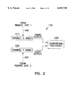
- FIG. 2 is a block diagram of a receiver for measuring the relative phase difference between different transmissions
- FIG. 3 is a diagram of one environment in which the present alignment system may operate
- FIG. 4 is a diagram of one environment in which the present alignment system may operate
- FIG. 5 is a plot of relative phase difference as a function of axis ratio according to one embodiment of the present invention.
- FIG. 6 is a plot of the relative phase difference as a function of the square of the length of the minor axis according to one embodiment of the present invention.
- FIG. 7 is a flow diagram showing the alignment procedure according to one embodiment of the present invention.
- FIG. 8 is a flow diagram showing a coarse alignment and fine alignment according to one embodiment of the present invention.
- FIG. 9 is a flow diagram showing one example of signal comparison and transmitter alignment according to one embodiment of the present invention.
- FIG. 10 is a diagram showing a directional antenna receiver system according to one embodiment of the present invention.
- FIG. 11A is a block diagram of the pulsed tone signal as transmitted by the control site
- FIG. 11B is a block diagram of the pulsed tone signal as received by the remote site
- FIG. 12 shows prediction of the zero crossing between adjacent sample pairs
- FIG. 13 shows error in predicted or estimated zero crossings with respect to the position of samples relative to "true" zero crossing
- FIG. 14 shows error magnitude as a function of signal to noise ratio
- FIG. 15 shows standard deviation as a function of signal to noise ratio
- FIG. 16 shows the calibration module and the interrelationship of FIGS. 16A, 16B, 16C, 16D, 16E, and 16F according to one embodiment of the present invention
- FIG. 16A shows how the calibration module stores sample pairs according to one embodiment of the present invention
- FIG. 16B shows how the calibration module validates sample pairs according to one embodiment of the present invention
- FIG. 16C shows how the calibration module calculates zero crossings for valid transition sample pairs according to one embodiment of the present invention
- FIG. 16D shows how the calibration module averages predicted zero crossings according to one embodiment of the present invention
- FIG. 16E shows how the calibration module locates positive and negative peaks according to one embodiment of the present invention
- FIG. 16F shows how the calibration module calculates total delay according to one embodiment of the present invention.
- FIG. 17 is an illustration of measurement of link delay using threshold triggering and a discrete-time Fourier transform.
- FIG. 1 shows one environment in which the present invention may be practiced.
- two remote sites 110 and 120 contribute to the total signal received by receiver 130 in the overlap region.
- the audio signal at the central site 100 is split and passes to each remote site over a link consisting, at each end, of a multiplexer 112 and a microwave transceiver 114.
- Other links may be used without departing from the scope of the present invention.
- microwave links the system could employ optical fiber links.
- the system in FIG. 1 shows two channels, A and B, to demonstrate the present system. Other numbers of channels are possible without departing from the scope of the present invention.
- the additional delay is added to the site delay 110 or 120, however several other embodiments exist.
- the additional delay is introduced at the central site 100.
- Other delay sources are possible without departing from the present invention.
- the present system is also applicable to the case where a transmitting site is located at the central site 100, except that in this case one of the signal paths does not contain any multiplexer or microwave equipment.
- one approach is to select one repeater of a particular channel as a reference transmitter and temporally align all of the other repeaters transmitting on a different channel to the reference transmitter. After all of the other repeaters transmitting on a different channel are temporally aligned, the remaining transmitters of the particular channel are aligned. This alignment is performed such that the simulcast situation is avoided throughout the alignment. The alignment is more reliable if simulcast is avoided, since there is no distortion due to the out-of-phase components at the receiver 130.
- FIG. 7 shows the operation of this embodiment.
- a reference transmitter is selected (710) and a second transmitter is selected which has a different channel (720).
- the second transmitter is aligned to the first transmitter (730).
- the remaining transmitters are aligned so that the simulcast condition is avoided (740).
- Alignment is accomplished by the method shown in FIGS. 8 and 9. Alignment is performed using a coarse adjustment (810) and a subsequent fine adjustment (820). Alignment is performed by demodulating a first transmitter channel (910) and a second transmitter channel (920), comparing the signals and implementing a delay in the leading transmitter to equalize the delay times (930).
- the delay implementation must be consistent so that the reference channel remains at a constant phase, so that all the other transmitters are aligned to it.
- the reference transmitter receives an initial delay which exceeds the maximum possible delay difference between any two transmissions in the system. This maximum delay ensures that all of the remaining transmitters may be aligned to the reference by adding delay.
- Other methods may be incorporated without departing from the scope and spirit of the present invention. For example, one embodiment may provide a global reduction of the excess delay imposed on the transmitters after all transmitters are aligned. This would efficiently zero the smallest delay value of each transmitter to globally reduce the latency of the transmitter system. Other variations are possible without departing from the scope and spirit of the present invention.
- channel A repeater 116 of remote site 1 110 is designated as a reference transmitter
- the channel B transmitters of the system are temporally aligned to channel A repeater 116.
- channel B repeater 118 and channel B repeater 128 are temporally aligned to the reference transmitter, repeater 116.
- the remaining channel A transmitters, besides the reference transmitter are aligned to at least one of the aligned channel B transmitters.
- the channel A repeater 126 of remote site 2 120 is aligned either to (1) the channel B repeater 118 or (2) the channel B repeater 128 using the temporal alignment technique discussed herein. In either of these possible alignments, the simulcast condition is avoided, since like-channel alignments are avoided.
- the selection of a reference transmitter serves to provide a "starting point" for the calibration of all transmitters in the system. As each transmitter is aligned, it too can serve as a reference for another transmitter of different channel. Therefore, the order of the alignment of the transmitters may be varied. For instance, in the above example, presuming that the channel A repeater 116 is used as an original reference, the following alignment permutations are possible:
- Channel B repeater 118 aligned relative to Channel A repeater 116
- Channel B repeater 128 aligned relative to Channel A repeater 116
- Channel A repeater 126 aligned relative to Channel B repeater 118
- Channel B repeater 118 aligned relative to Channel A repeater 116
- Channel B repeater 128 aligned relative to Channel A repeater 116
- Channel A repeater 126 aligned relative to Channel B repeater 128
- Channel B repeater 128 aligned relative to Channel A repeater 116
- Channel B repeater 118 aligned relative to Channel A repeater 116
- Channel A repeater 126 aligned relative to Channel B repeater 118
- Channel B repeater 128 aligned relative to Channel A repeater 116
- Channel B repeater 118 aligned relative to Channel A repeater 116
- Channel A repeater 126 aligned relative to Channel B repeater 128
- Channel B repeater 118 aligned relative to Channel A repeater 116
- Channel A repeater 126 aligned relative to Channel B repeater 118
- Channel B repeater 128 aligned relative to Channel A repeater 116
- Channel B repeater 128 aligned relative to Channel A repeater 116
- Channel A repeater 126 aligned relative to Channel B repeater 128
- Channel B repeater 118 aligned relative to Channel A repeater 116
- Channel B repeater 118 aligned relative to Channel A repeater 116
- Channel A repeater 126 aligned relative to Channel B repeater 118
- Channel B repeater 128 aligned relative to Channel A repeater 126
- Channel B repeater 128 aligned relative to Channel A repeater 116
- Channel A repeater 126 aligned relative to Channel B repeater 128
- Channel B repeater 118 aligned relative to Channel A repeater 126
- the flexibility in transmitter alignment of the present invention facilitates alignment of different repeater topologies.
- the alignment method may be used to align the various transmitters found in FIG. 3.
- FIG. 3 shows four multichannel repeaters 302, 304, 306, and 308 having reception regions 312, 314, 316, and 318, respectively, and a central station 320.
- the present alignment system provides a consistent calibration for all transmitters in the system, since a first reference transmitter is used to align the remaining transmitters.
- the overlapping transmission areas, K, L, M, and N present a number of alignment permutations, as demonstrated in the previous example.
- topologies may be aligned using the present method and the topologies discussed herein are for illustration of alternate embodiments of the present invention and are not intended in an exclusive or limiting sense.
- the order of which each transmitting source is aligned depends on whether an aligned transmitter of the opposite channel is present within the simulcast region of interest.
- FIG. 4 shows an alternate repeater topology having overlapping reception areas Q, R, and S. If one of the transmitters is used as a reference, the remaining transmitters may be aligned to the reference transmitter. Every transmitter in FIG. 4 may be aligned to the reference transmitter since there is an overlap region linking each of the repeaters.
- This system for alignment may be extended to applications where more than two transmitting channels are present. For example, in one embodiment, a reference channel is selected and the "other-channel" transmitters are aligned. After these transmitters are aligned, the remaining transmitters are aligned, and the simulcast situation is avoided during alignment, as described above. As illustrated above, several alignment permutations are possible without departing from the scope and spirit of the present invention.
- the temporal alignment procedure is performed by having a special receiver 130 capable of receiving the different channels present in the overlap region, as shown in FIG. 2.
- Two radios a channel X radio 210 and a channel Y radio 220, receive different channels and output a signal which is fed into comparison equipment 230 to measure the phase difference between signals received from the simulcast.
- FIG. 2 shows the signals 240 and 250 as received from different remote sites, however, it is contemplated within the present invention that the signals could originate from the same remote site for temporal alignment as described above. Additionally, FIG. 2 shows only two radios, however, this block diagram is illustrative and is not intended in an exclusive or limiting sense. In alternate embodiments, several channels may be received by several radios without departing from the scope of the present invention.
- each radio 210 and 250 are compared, giving the phase and time delay between the signals.
- the transmitters are selectively activated such that each radio receives transmissions from a single channel source per alignment. That is, there is no simulcast condition during the alignment process.
- repeaters are disabled as needed to ensure that the simulcast of same-frequency signals is not received by the receiver 130.
- the alignment is performed using a coarse adjustment and a fine adjustment, as shown in FIG. 8.
- a periodic signal may be used to establish a phase relationship between the different channels during temporal alignment.
- a pulse-like signal is used as the audio signal at the central site 100.
- a Hewlett-Packard 3314A Function Generator has a mode in which it produces a burst of approximately one and one-half cycles of a tone. These bursts must be separated in time by a period considerably longer than the total path delays. In this way each radio in the overlap region will produce a burst which can, for example, be displayed on an oscilloscope and can provide direct and quick measurement of the difference between the path delays.
- phase detection may be employed, and the use of an oscilloscope is not intended to be limiting or exclusive.
- a computer having sound analysis software measures the time delay between tone bursts.
- audio signals may be substituted, such as the use of a digital pulsetrain for performing the coarse adjustment.
- the digital pulsetrain has a periodicity which is longer than the total path delay to facilitate identification of the path delay.
- the latency measured between pulse rising or falling edges is recorded and used to temporally align the system. The appropriate delay is then implemented in the transmitter which is being aligned. In this way, one transmitter is brought into approximate temporal alignment with the reference transmitter.
- a pure tone is used as the central site audio signal for fine adjustment (820).
- the audio signals produced by the radios in the overlap will also be tones, with some small time delay between them which is determined by the accuracy of the coarse adjustment.
- One method of comparing the tones to determine the time delay between them is to use them as the inputs of an oscilloscope which is set on X-Y display.
- the display will show a line. In the most general case, however, the display will show an ellipse. The ratio:
- the polynomial fit in FIG. 5 indicates the phase delay is 15 degrees, which for a 1 KHz tone is 41.7 microseconds.
- the use of a 1 KHz tone is used to demonstrate the measurement of the time delay, and is not intended as an exclusive or limiting example. Other tone frequencies may be used without departing from the scope and spirit of the present invention.
- FIG. 5 shows how phase delay and the square of [length of minor axis] are related. Again, the appropriate delay is implemented in the channel which is being aligned.
- one channel e.g., channel A
- site 1 one site
- All other channels of all sites are timed to it.
- channel A of all sites other than site 1 are timed to a channel of site I other than A. In this way all channels at all sites have been referenced, directly or indirectly, to channel A of site 1.
- this problem is overcome by using an averaging technique. Temporal alignment is performed as stated above. Next, the radios are tuned to the opposite channel and the measurement is repeated. The average of these two delays is then implemented. This method compensates for the differences in delays for each radio.
- fine tuning is accomplished by a variable frequency generator which provides a tone whose frequency is swept across the audio spectrum instead of a single frequency tone, as discussed above.
- the tone frequency is swept from 300 Hz to 3000 Hz and the time delay information is recorded to map the time delay as a function of audio frequency. This method characterizes the time delay for various paths for different frequencies in the audio spectrum.
- any periodic signal is used to provide the fine adjustment.
- the periodic signal may be an audio tone or a digital pulsetrain.
- the periodic signal has a first periodic component which has a periodicity which is larger than the anticipated relative time delays for a coarse adjustment, and a second periodic component which provides relatively fine resolution for a fine adjustment. Therefore, in this embodiment, the fine tuning is achieved by measuring the relative delay of some characteristic portion of the periodic signals arriving simultaneously at the remote receiver, and calculating a time correction factor from the relative delay.
- Channels may be different frequencies, such as different AM, FM, or Single Sideband communications frequencies.
- channels contemplated by this application are not limited to these examples and expressly include several other communications channels.
- channels includes spread spectrum communications, digital communications, such as packetized communications, or any other communications mode whereby independent communications may take place, such as optical communications. Therefore, other channels are possible without departing from the scope of the present invention.
- the link equipment may exhibit different delays at different audio frequencies.
- one equalized path delays at one particular audio frequency then the delay at other frequencies would not, in general, be precisely equalized. This would introduce distortion into the received signal.
- One method commonly used to alleviate frequency dependent delays is to introduce a compensating filter which has an inverse frequency dependent delay characteristic.
- These compensating filters are typically allpass filters, which can be implemented using discrete circuit elements or through Digital Signal Processing techniques.
- One embodiment of the present invention uses a software driven analysis program for audio analysis, such as Spectra Plus version 3.0 from Pioneer Hill Software, 24460 Mason Rd, Poulsbo, Wash. 98370.
- This program combines a variety of instrument functions into one package. For example, one can look at the amplitudes of signals as a function of time, as with an oscilloscope. There are also operating modes for examining signal amplitude or phase versus frequency. Other capabilities include audio signal generator and distortion analysis modes.
- the software analysis program provides a compact and unified analysis means for monitoring the phase data.
- the calibration is performed once upon the setup of the system, and then subsequently as needed. In alternate embodiments, the calibration is performed regularly to ensure system performance.
- FIG. 10 shows a system having a receiver 1010 which has dual directional antennas.
- the first antenna has an anisotropic reception pattern which is directed toward the transmitter at site 1.
- the second antenna is pointed to receive signals from the transmitter at site 2.
- This system provides alignment of the two transmitters at site 1 and site 2 using the phase detection methods described herein.
- the transmissions are on the same channel, so the receiver is located within a simulcast overlap region, however, the signals are discriminated using the directional antennas at the receiver 1010.
- the directional nature of the antennas provides adequate signal separation so that the signals from the different transmitters may be discriminated, even when the simulcast condition is present.
- the receiver includes two or more radios which may be tuned to same or different channels.
- Each antenna is pointed at a particular transmitter and the alignment procedure is performed using the phase detection and delay compensation system described above. This system works with the simulcast condition, since the decibel separation between transmitters provides the adequate signal separation to perform the delay measurements without the distortion present generally to isotropic receivers.
- Performance of this system is improved as the directionality of the channels, and the decibel separation of each transmitter is increased.
- Alternate embodiments may incorporate different numbers of receivers and directional antennas without departing from the scope and spirit of the present invention.
- link delays are measured using signals from the global positioning satellite (GPS) system.
- the first step involves the control site transmitting several cycles of a tone on a 1 pulse-per-second (pps) signal generated by the local GPS unit. This process is illustrated in FIGS. 11A and 11B.
- samples are collected following detection of the 1 pps signal from the remote site's GPS unit. These samples are analyzed in order to estimate the times when the received signal crosses zero.
- the simplest method for performing this operation is to determine when sign changes occur between adjacent samples. One then interpolates, using the two samples whose signs are different, in order to estimate when the actual signal crossed zero. By having the test signal contain several cycles one is able to average many zero crossings, which improves the accuracy of this technique when noise is present.
- the theoretical limitations of this method are best understood by considering different values of the link SIN, which is the approach taken in the following discussion.
- a calibration module processes a buffer of data to calculate the link delay between a link transmitter and a link receiver.
- Delay information is digitally sampled in the time domain according to the One Pulse Per Second (PPS) signal of the Global Positioning System. Alternate embodiments use any other common timing reference signal.
- PPS Pulse Per Second
- FIG. 16 One embodiment of the calibration module is shown generally in FIG. 16, and each step is broken down in the flow diagrams of FIGS. 16A-F, as described below.
- the calibration module begins processing information when the buffer fills with data; for example, 512 samples representing a 1 KHz tone sampled at 8000 samples/second. As shown in FIG. 16A, the calibration module skips over a leading delay and locates a predetermined threshold value which indicates the place where the tone starts. The sample number where the data exceeds the threshold value is stored is indicative of the number of clock periods of the link delay.
- the threshold value is approximately 0.2 volts in one system, however, other buffer sizes and threshold values may be used without departing from the scope and spirit of the present invention.
- the calibration module finds transition sample pairs which are indicative of a zero crossing event.
- the transition sample pairs are where the tone signal transitions from a positive value to a negative value and where the tone signal transitions from a negative value to a positive value.
- the calibration module stores the sample numbers where transitions are located and the value of each of the transition sample pairs. This process continues until a fixed number of transition sample pairs are found or all of the samples are processed. For example, in one embodiment 18 transition sample pairs are located or all the 512 samples are processed, whichever comes first.
- the calibration module validates the transition sample pairs by counting the number of samples between each transition sample pair.
- the pairs which are determined to be in the proper spacing are deemed “valid" transition sample pairs and the remaining transition sample pairs are labeled "invalid.”
- the valid transition sample pairs are flagged as such and the invalid samples are flagged as invalid. For example, in one embodiment a logic one bit is associated with the valid pairs and a logic zero value is associated with the invalid pairs.
- the calibration module calculates and stores the predicted crossing point for each valid transition sample pair.
- a delay for each zero crossing is found by comparing the magnitude of each sample in the pair to obtain a fractional result.
- the result is compared to a series of entries in a delay table to indicate where the zero crossing is estimated to occur and its associated delay value.
- the delay value is added when the second sample exceeds the first sample, and it is subtracted when the first sample exceeds the second sample of the valid transition sample pairs.
- the delay table is precalculated and stored as a lookup table to reduce the amount of time needed to calculate the latency associated with each possible first sample:second sample ratio.
- the samples are always associated with a fractional value and the delay is added or subtracted as demonstrated above.
- the calibration module averages the predicted zero crossing points and stores the average value. This averaging reduces the effects of random amplitude noise.
- the calibration module locates and stores the peak positive and peak negative values and their associated sample numbers in a buffer.
- the peak positive and peak negative values are then validated by measuring the samples between the peaks and the valid peaks are marked.
- the first valid peak is then used to predict the first positive to negative zero crossing using the averaged zero cross value.
- the first zero crossing is located by subtracting 1/2 the tone period from the first positive to negative zero crossing which was just previously predicted using the averaged zero cross value.
- the first zero crossing obtained in this last step is indicative of the overall link delay, D.
- a coarse delay is used in combination with a fine delay to produce the overall link delay, D.
- the link transmission is delayed to compensate for the overall link delay, D.
- the compensation is performed at the remote site. In another embodiment, the compensation is performed at the central site. Multiple remote sites may be calibrated by equalizing overall link delays in the system.
- link delays are measured using synchronization signals from the global positioning satellite (GPS) system.
- the first step involves the control site transmitting several cycles of a tone (a tone burst) on a 1 pulse-per-second (PPS) mark signal generated by the local GPS unit. This process is illustrated in FIGS. 11A and 11B.
- samples are collected following detection of the 1 PPS signal from the remote site's GPS unit.
- the sampling clock used for acquisition at the remote site is frequency locked to the sampling clock used for generation at the control site. This frequency locking is accomplished via the 10 MHz GPS synchronization signal.
- the remote site samples are stored in a buffer and analyzed in order to estimate the starting time of the received tone burst.
- One method for calculate the time delay is to use the Discrete-Time Fourier Transform (DTFT) to find the starting phase of a segment of the tone burst.
- DTFT Discrete-Time Fourier Transform
- a segment is simply a particular subset of the samples that make up the tone burst. If the cycle in which the segment starts is known, the starting phase can be used to estimate link delay which is accurate to the degree required for the simulcast.
- This approach is independent of the amplitude of the tone burst and is exact in the absence of noise. In addition, it can be done in a computationally efficient manner on a DSP chip.
- FIG. 17 shows a 5 cycle tone burst with a normalized frequency of 0.125.
- the threshold shown is a negative value.
- the first point in the data buffer to fall below this threshold is indicated by t thresh .
- t start 2 cycles ahead of t thresh and represents a suitable starting point for the segment. From the t start point onward, the segment must include an integer number of cycles. For this reason, it is crucial to select the tone burst frequency such that its period is an integer number of samples (e.g., a 1 kHz burst with an 8 kHz sampling frequency results in a period of 8 samples.)
- x(t) be the signal stored in the data buffer.
- the start phase of the segment is given by
- the threshold may be adjusted for noisy environments, to decrease the possibility of noise triggering the discrete-time Fourier transform operation.
- noisy samples include, but are not limited to, statistical analysis of a number of calculated time delays.
- an average delay and a standard deviation are calculated and samples greater than the standard deviation are discarded.
- One embodiment will remove noisy samples by selecting a maximum change in delay, say 5 ⁇ sec, for example, and then discarding samples which deviate more than 5 ⁇ sec from an average delay.
- Other embodiments for treating noisy samples are possible without departing from the scope and spirit of the present invention.
Abstract
Description
r=length of minor axis/length of major axis Eqn. 3
time delay (seconds)=(phase delay (degrees)/360)×(1/frequency of tone (Hz))
f.sub.sample =(t.sub.+ +t.sub.-).sup.-1 f(t.sub.+)=sin(2πf.sub.tone t.sub.+), f(-t.sub.-)=-sin(2πf.sub.tone t.sub.-), and
y(t.sub.int)=0, which allows us to rewrite Eqn. 5 as: ##EQU3## As shown in FIG. 12, the true zero crossing occurs at t=0, implying that Eqn. 6 describes the error in our estimate of the position of the zero crossing. A MATLAB program, presented in Appendix A, was used to plot t.sub.int for various tone frequencies, sample rates, and positions of the sampling points relative to the true zero crossing. FIG. 13 shows the error as the sampling position is varied for
f.sub.tone =1kHz and f.sub.sample =8kHz. One finds that 0≦|t.sub.int |≦1.27 μsec, where
t.sub.int =0 for t.sub.+ =0, 62.5, 125 μsec and |t.sub.int |≈1.3 μsec for t.sub.+ ≈26, 99 μsec
θ.sub.start =tan.sup.-1 [imag(X(ω.sub.0))/real(X(ω.sub.0))]
Δt=Δθ/2π(f.sub.burst /f.sub.sampling).
Claims (13)
Priority Applications (1)
| Application Number | Priority Date | Filing Date | Title |
|---|---|---|---|
| US08/838,853 US6049720A (en) | 1996-04-12 | 1997-04-11 | Link delay calculation and compensation system |
Applications Claiming Priority (3)
| Application Number | Priority Date | Filing Date | Title |
|---|---|---|---|
| US1531196P | 1996-04-12 | 1996-04-12 | |
| US2776396P | 1996-10-07 | 1996-10-07 | |
| US08/838,853 US6049720A (en) | 1996-04-12 | 1997-04-11 | Link delay calculation and compensation system |
Publications (1)
| Publication Number | Publication Date |
|---|---|
| US6049720A true US6049720A (en) | 2000-04-11 |
Family
ID=27360305
Family Applications (1)
| Application Number | Title | Priority Date | Filing Date |
|---|---|---|---|
| US08/838,853 Expired - Lifetime US6049720A (en) | 1996-04-12 | 1997-04-11 | Link delay calculation and compensation system |
Country Status (1)
| Country | Link |
|---|---|
| US (1) | US6049720A (en) |
Cited By (13)
| Publication number | Priority date | Publication date | Assignee | Title |
|---|---|---|---|---|
| US6229791B1 (en) * | 1998-07-06 | 2001-05-08 | International Business Machines Corporation | Method and system for providing partitioning of partially switched networks |
| US20020128044A1 (en) * | 2001-01-19 | 2002-09-12 | Chang Donald C.D. | Communication system for mobile users using adaptive antenna |
| WO2002082790A1 (en) * | 2001-04-03 | 2002-10-17 | Porta Systems Corporation | Sound card based measurements for testing telephone lines |
| US20030125890A1 (en) * | 2002-01-02 | 2003-07-03 | Nagamatsu Brian H. | System and method for remote data acquisition, monitoring and control |
| US6711409B1 (en) * | 1999-12-15 | 2004-03-23 | Bbnt Solutions Llc | Node belonging to multiple clusters in an ad hoc wireless network |
| US20040198401A1 (en) * | 2002-10-18 | 2004-10-07 | Rodgers William E. | Method of steering smart antennas |
| US6973053B1 (en) | 2000-09-12 | 2005-12-06 | Bbnt Solutions Llc | Using direct cluster member to cluster member links to improve performance in mobile communication systems |
| US7120456B1 (en) | 2001-11-07 | 2006-10-10 | Bbn Technologies Corp. | Wireless terminals with multiple transceivers |
| US7301608B1 (en) | 2005-01-11 | 2007-11-27 | Itt Manufacturing Enterprises, Inc. | Photon-counting, non-imaging, direct-detect LADAR |
| US20080064335A1 (en) * | 1999-02-16 | 2008-03-13 | Mitsubishi Denki Kabushiki Kaisha | Radio Communication System, a Transmitter and a Receiver |
| US20090011789A1 (en) * | 2001-01-19 | 2009-01-08 | Chang Donald C D | Multiple basestation communication system having adaptive antennas |
| US20100136991A1 (en) * | 2007-04-23 | 2010-06-03 | Telefonaktiebolaget Lm Ericsson (Publ) | Method of Transmitting Down Link Data |
| US20100215014A1 (en) * | 2006-01-23 | 2010-08-26 | Alan Edward Jones | Quasi Synchronous Transmission in Cellular Networks |
Citations (97)
| Publication number | Priority date | Publication date | Assignee | Title |
|---|---|---|---|---|
| US34036A (en) * | 1861-12-24 | Improvement in mode of attaching breeching to shafts of carriages | ||
| DE323678C (en) * | 1920-08-02 | Paul Neidhardt | Impeller water meter | |
| NL6508593A (en) * | 1965-07-02 | 1967-01-03 | ||
| US3867700A (en) * | 1972-11-15 | 1975-02-18 | Keith H Wycoff | Tone operated single side-band communication system |
| US4085368A (en) * | 1976-08-30 | 1978-04-18 | Bell Telephone Laboratories, Incorporated | Interference canceling method and apparatus |
| US4125744A (en) * | 1948-12-24 | 1978-11-14 | Bell Telephone Laboratories, Incorporated | Communication system |
| US4131850A (en) * | 1977-02-18 | 1978-12-26 | Glade Wilcox | Single side band radio apparatus |
| US4131849A (en) * | 1976-10-21 | 1978-12-26 | Motorola, Inc. | Two-way mobile radio voice/data shared communications system |
| EP0004702A1 (en) * | 1978-04-10 | 1979-10-17 | Motorola, Inc. | Simulcast transmission system having phase-locked remote transmitters |
| GB1574599A (en) * | 1977-04-20 | 1980-09-10 | Plessey Co Ltd | Fault indication in repeatered telecommunications transmission-line |
| EP0020893A1 (en) * | 1979-06-08 | 1981-01-07 | Robert Bosch Gmbh | Radio network |
| US4255620A (en) * | 1978-01-09 | 1981-03-10 | Vbc, Inc. | Method and apparatus for bandwidth reduction |
| US4281413A (en) * | 1979-12-03 | 1981-07-28 | General Electric Company | Multichannel radio telephone system |
| US4325057A (en) * | 1980-06-30 | 1982-04-13 | Bishop-Hall, Inc. | School bus approach notification method and apparatus |
| US4406016A (en) * | 1981-11-27 | 1983-09-20 | The United States Of America As Represented By The Secretary Of The Army | VHF Sensor in-band radio relay |
| US4490830A (en) * | 1981-07-22 | 1984-12-25 | Nippon Electric Co., Ltd. | Radio signal transmission system including a plurality of transmitters for transmitting a common signal |
| US4516269A (en) * | 1982-12-10 | 1985-05-07 | Michigan Consolidated Gas Company | Automatic equalization for a simulcast communication system |
| US4607257A (en) * | 1981-12-25 | 1986-08-19 | Nippon Electric Co. Ltd. | Remote calibrating system for satellite time |
| US4679243A (en) * | 1984-08-17 | 1987-07-07 | National Research Development Corporation | Data transmission using a transparent tone-in band system |
| US4696052A (en) * | 1985-12-31 | 1987-09-22 | Motorola Inc. | Simulcast transmitter apparatus having automatic synchronization capability |
| US4696051A (en) * | 1985-12-31 | 1987-09-22 | Motorola Inc. | Simulcast transmission system having automtic synchronization |
| US4701934A (en) * | 1985-09-03 | 1987-10-20 | Motorola, Inc. | Method of doppler searching in a digital GPS receiver |
| US4726069A (en) * | 1984-05-18 | 1988-02-16 | Stevenson Carl R | A muiti-mode modulation and demodulation system and method |
| US4802191A (en) * | 1986-02-28 | 1989-01-31 | National Research Development Corporation | Data transmission using a transparent tone-in band system |
| US4803739A (en) * | 1984-12-10 | 1989-02-07 | Nippon Telegraph And Telegraph Corporation | SSB communication system |
| US4852090A (en) * | 1987-02-02 | 1989-07-25 | Motorola, Inc. | TDMA communications system with adaptive equalization |
| US4862098A (en) * | 1988-05-04 | 1989-08-29 | General Electric Company | Continuous-wave-modulation detectors using prediction methods |
| US4972410A (en) * | 1989-07-20 | 1990-11-20 | Electrocom Automation, Inc. | Method and apparatus for controlling signal coherency in simulcast systems |
| US4994804A (en) * | 1988-03-15 | 1991-02-19 | Kabushiki Kaisha Toshiba | Double integration delta-sigma modulation analog to digital converter |
| US5003617A (en) * | 1988-10-21 | 1991-03-26 | Motorola, Inc. | Simulcast broadcasting system and method |
| US5038403A (en) * | 1990-01-08 | 1991-08-06 | Motorola, Inc. | Simulcast system with minimal delay dispersion and optimal power contouring |
| US5060240A (en) * | 1989-02-14 | 1991-10-22 | Motorola, Inc. | Simulcast system and channel unit |
| US5061934A (en) * | 1990-11-09 | 1991-10-29 | The United States Of America As Represented By The Secretary Of The Air Force | Hybrid clutter cancellation method and system for improved radar performance |
| US5077759A (en) * | 1988-02-10 | 1991-12-31 | Nec Corporation | Phase adjusting system for a radio communication system |
| US5105439A (en) * | 1989-08-11 | 1992-04-14 | Motorola, Inc. | Delay equalization detector |
| US5113413A (en) * | 1989-06-09 | 1992-05-12 | Ericsson Ge Mobile Communications Inc. | Voter arrangement for multiple site PST RF trunking system |
| US5117424A (en) * | 1989-07-20 | 1992-05-26 | Electrocom Automation L.P. | Method and apparatus for setting clock signals to predetermined phases at remote broadcast sites in simulcast systems |
| US5117503A (en) * | 1989-10-02 | 1992-05-26 | Motorola, Inc. | Directional antenna arrangement method for simulcast broadcasting |
| US5127101A (en) * | 1991-02-01 | 1992-06-30 | Ericsson Ge Mobile Communications Inc. | Simulcast auto alignment system |
| US5128934A (en) * | 1990-06-29 | 1992-07-07 | Motorola, Inc. | Multiple transmitter message transmission system and method therefor |
| US5131010A (en) * | 1989-10-12 | 1992-07-14 | General Electric Company | Voice guard digital voter for multiple site PST RF trunking system |
| US5134630A (en) * | 1989-04-12 | 1992-07-28 | National Research Development Corporation | Method and apparatus for transparent tone-in-band transmitter, receiver and system processing |
| USRE34036E (en) | 1984-06-06 | 1992-08-18 | National Research Development Corporation | Data transmission using a transparent tone-in band system |
| US5142692A (en) * | 1989-06-16 | 1992-08-25 | Seiko Corp. | Transmitting information with cut and flip spectrum |
| US5155859A (en) * | 1991-03-28 | 1992-10-13 | Motorola, Inc. | Simulcast transmission system having automatic audio equalization |
| EP0515214A1 (en) * | 1991-05-24 | 1992-11-25 | BRITISH TELECOMMUNICATIONS public limited company | Radio system with measurement and adjustment of transfer delay |
| US5172396A (en) * | 1988-10-20 | 1992-12-15 | General Electric Company | Public service trunking simulcast system |
| US5184242A (en) * | 1989-12-15 | 1993-02-02 | Nec Corporation | Supervisory circuit for optical repeater |
| US5194871A (en) * | 1982-03-01 | 1993-03-16 | Western Atlas International, Inc. | System for simultaneously deriving position information from a plurality of satellite transmissions |
| US5201061A (en) * | 1990-07-23 | 1993-04-06 | Motorola, Inc. | Method and apparatus for synchronizing simulcast systems |
| WO1993007681A1 (en) * | 1991-10-04 | 1993-04-15 | Motorola, Inc. | Simulcast synchronization and equalization system and method therefor |
| US5212807A (en) * | 1991-03-28 | 1993-05-18 | Motorola, Inc. | Method of automatic path map generation for simulcast transmission system |
| US5218717A (en) * | 1990-01-10 | 1993-06-08 | Rohde & Schwarz Gmbh & Co. Kg | Simulcast transmission system with improved synchronizing system |
| US5218621A (en) * | 1991-04-04 | 1993-06-08 | Motorola, Inc. | Adaptive digital equalization filter |
| US5227741A (en) * | 1992-01-22 | 1993-07-13 | Glenayre Electronics Ltd. | Variable speed asynchronous modem |
| EP0551126A1 (en) * | 1992-01-10 | 1993-07-14 | Nec Corporation | Simulcast radio paging system |
| US5239672A (en) * | 1991-06-28 | 1993-08-24 | Motorola, Inc. | Synchronization method and apparatus for simulcast transmission system |
| US5243299A (en) * | 1992-01-22 | 1993-09-07 | Glenayre Electronics, Inc. | Variable speed asynchronous modem |
| US5261118A (en) * | 1991-10-04 | 1993-11-09 | Motorola, Inc. | Simulcast synchronization and equalization system and method therefor |
| US5280629A (en) * | 1991-12-06 | 1994-01-18 | Motorola, Inc. | Technique for measuring channel delay |
| US5287550A (en) * | 1990-12-24 | 1994-02-15 | Motorola, Inc. | Simulcast scheduler |
| US5295178A (en) * | 1990-12-03 | 1994-03-15 | Ericsson Ge Mobile Communications Inc. | Digital signal processor for radio base station |
| US5319374A (en) * | 1993-02-02 | 1994-06-07 | Trimble Navigation Limited | Precise universal time for vehicles |
| US5327581A (en) * | 1992-05-29 | 1994-07-05 | Motorola, Inc. | Method and apparatus for maintaining synchronization in a simulcast system |
| US5327144A (en) * | 1993-05-07 | 1994-07-05 | Associated Rt, Inc. | Cellular telephone location system |
| US5353342A (en) * | 1992-12-08 | 1994-10-04 | Bell Communications Research, Inc. | Adaptive multitone signaling method |
| US5353307A (en) * | 1991-09-03 | 1994-10-04 | General Electric Company | Automatic simulcast alignment |
| US5361398A (en) * | 1993-01-29 | 1994-11-01 | Motorola, Inc. | Method and apparatus for transmission path delay measurements using adaptive demodulation |
| US5365569A (en) * | 1992-08-17 | 1994-11-15 | Glenayre Electronics, Ltd. | Digital simulcast transmission system |
| US5369682A (en) * | 1992-08-17 | 1994-11-29 | Glenayre Electronics, Inc. | Digital simulcast transmission system |
| US5392278A (en) * | 1990-08-28 | 1995-02-21 | Ericsson Ge Mobile Communications Inc. | Distributed multisite system architecture |
| US5398263A (en) * | 1993-01-14 | 1995-03-14 | Motorola, Inc. | Autonomous pulse train timing controls for time-mark alignment |
| US5406842A (en) * | 1993-10-07 | 1995-04-18 | Motorola, Inc. | Method and apparatus for material level measurement using stepped frequency microwave signals |
| US5408681A (en) * | 1993-08-16 | 1995-04-18 | The United States Of America As Represented By The Secretary Of The Navy | Automatic repeater station for signal transmissions |
| US5414734A (en) * | 1993-01-06 | 1995-05-09 | Glenayre Electronics, Inc. | Compensation for multi-path interference using pilot symbols |
| US5416808A (en) * | 1992-03-31 | 1995-05-16 | Glenayre Electronics, Inc. | Apparatus for synchronizing a plurality of clocks in a simulcast network to a reference clock |
| US5423056A (en) * | 1991-02-25 | 1995-06-06 | Pagemart, Inc. | Adaptive cellular paging system |
| US5423058A (en) * | 1992-10-05 | 1995-06-06 | Motorola, Inc. | Simulcast transmission system with selective call tones |
| US5423059A (en) * | 1993-07-29 | 1995-06-06 | Motorola Inc. | Method for enhancing signal quality in a simulcast communication system |
| US5448758A (en) * | 1993-02-26 | 1995-09-05 | Motorola, Inc. | Simulcast group determination of best signal by master site |
| US5448570A (en) * | 1993-03-17 | 1995-09-05 | Kyocera Corporation | System for mutual synchronization and monitoring between base stations |
| US5465405A (en) * | 1992-07-30 | 1995-11-07 | Raytheon Company | Apparatus and method for detecting signals |
| US5473638A (en) * | 1993-01-06 | 1995-12-05 | Glenayre Electronics, Inc. | Digital signal processor delay equalization for use in a paging system |
| US5477539A (en) * | 1993-07-23 | 1995-12-19 | Ericsson Inc. | Narrow band simulcast system having low speed data distribution |
| US5481258A (en) * | 1993-08-11 | 1996-01-02 | Glenayre Electronics, Inc. | Method and apparatus for coordinating clocks in a simulcast network |
| US5483575A (en) * | 1993-02-19 | 1996-01-09 | Ericsson Ge Mobile Communications Inc. | System for correlating RF usage in a trunked communication network based on channel assignments and channel drops for each call |
| US5483670A (en) * | 1987-06-03 | 1996-01-09 | Ericsson Ge Mobile Communications Inc. | Trunked radio repeater system with control channel monitoring feature |
| US5485632A (en) * | 1993-02-26 | 1996-01-16 | Motorola, Inc. | Method for initiating and determining simulcast transmission of a message |
| US5490172A (en) * | 1994-07-05 | 1996-02-06 | Airnet Communications Corporation | Reducing peak-to-average variance of a composite transmitted signal via out-of-band artifact signaling |
| US5513215A (en) * | 1993-09-20 | 1996-04-30 | Glenayre Electronics, Inc. | High speed simulcast data system using adaptive compensation |
| US5542119A (en) * | 1993-02-26 | 1996-07-30 | Motorola, Inc. | Method for selecting a highest quality signal for retransmission by base sites in a simulcast communication system |
| US5555546A (en) * | 1994-06-20 | 1996-09-10 | Kokusai Electric Co., Ltd. | Apparatus for decoding a DPCM encoded signal |
| US5590403A (en) * | 1992-11-12 | 1996-12-31 | Destineer Corporation | Method and system for efficiently providing two way communication between a central network and mobile unit |
| US5619564A (en) * | 1995-05-31 | 1997-04-08 | Lucent Technologies Inc. | Tone detector with improved performance in the presence of speech |
| US5668836A (en) * | 1994-12-29 | 1997-09-16 | Motorola, Inc. | Split frequency band signal digitizer and method |
| US5799000A (en) * | 1997-02-06 | 1998-08-25 | At&T Wireless Services, Inc. | Delay compensation |
| US5809397A (en) * | 1996-02-29 | 1998-09-15 | Motorola, Inc. | Method and apparatus for system synchronization in a messaging system |
-
1997
- 1997-04-11 US US08/838,853 patent/US6049720A/en not_active Expired - Lifetime
Patent Citations (101)
| Publication number | Priority date | Publication date | Assignee | Title |
|---|---|---|---|---|
| DE323678C (en) * | 1920-08-02 | Paul Neidhardt | Impeller water meter | |
| US34036A (en) * | 1861-12-24 | Improvement in mode of attaching breeching to shafts of carriages | ||
| US4125744A (en) * | 1948-12-24 | 1978-11-14 | Bell Telephone Laboratories, Incorporated | Communication system |
| NL6508593A (en) * | 1965-07-02 | 1967-01-03 | ||
| US3867700A (en) * | 1972-11-15 | 1975-02-18 | Keith H Wycoff | Tone operated single side-band communication system |
| US4085368A (en) * | 1976-08-30 | 1978-04-18 | Bell Telephone Laboratories, Incorporated | Interference canceling method and apparatus |
| US4131849A (en) * | 1976-10-21 | 1978-12-26 | Motorola, Inc. | Two-way mobile radio voice/data shared communications system |
| US4131850A (en) * | 1977-02-18 | 1978-12-26 | Glade Wilcox | Single side band radio apparatus |
| GB1574599A (en) * | 1977-04-20 | 1980-09-10 | Plessey Co Ltd | Fault indication in repeatered telecommunications transmission-line |
| US4255620A (en) * | 1978-01-09 | 1981-03-10 | Vbc, Inc. | Method and apparatus for bandwidth reduction |
| EP0004702A1 (en) * | 1978-04-10 | 1979-10-17 | Motorola, Inc. | Simulcast transmission system having phase-locked remote transmitters |
| EP0020893A1 (en) * | 1979-06-08 | 1981-01-07 | Robert Bosch Gmbh | Radio network |
| US4281413A (en) * | 1979-12-03 | 1981-07-28 | General Electric Company | Multichannel radio telephone system |
| US4325057A (en) * | 1980-06-30 | 1982-04-13 | Bishop-Hall, Inc. | School bus approach notification method and apparatus |
| US4490830A (en) * | 1981-07-22 | 1984-12-25 | Nippon Electric Co., Ltd. | Radio signal transmission system including a plurality of transmitters for transmitting a common signal |
| US4406016A (en) * | 1981-11-27 | 1983-09-20 | The United States Of America As Represented By The Secretary Of The Army | VHF Sensor in-band radio relay |
| US4607257A (en) * | 1981-12-25 | 1986-08-19 | Nippon Electric Co. Ltd. | Remote calibrating system for satellite time |
| US5194871A (en) * | 1982-03-01 | 1993-03-16 | Western Atlas International, Inc. | System for simultaneously deriving position information from a plurality of satellite transmissions |
| US5384574A (en) * | 1982-03-01 | 1995-01-24 | Western Atlas International, Inc. | System for determining position from suppressed carrier radio waves |
| US4516269A (en) * | 1982-12-10 | 1985-05-07 | Michigan Consolidated Gas Company | Automatic equalization for a simulcast communication system |
| US4726069A (en) * | 1984-05-18 | 1988-02-16 | Stevenson Carl R | A muiti-mode modulation and demodulation system and method |
| USRE34036E (en) | 1984-06-06 | 1992-08-18 | National Research Development Corporation | Data transmission using a transparent tone-in band system |
| US4679243A (en) * | 1984-08-17 | 1987-07-07 | National Research Development Corporation | Data transmission using a transparent tone-in band system |
| US4803739A (en) * | 1984-12-10 | 1989-02-07 | Nippon Telegraph And Telegraph Corporation | SSB communication system |
| US4701934A (en) * | 1985-09-03 | 1987-10-20 | Motorola, Inc. | Method of doppler searching in a digital GPS receiver |
| US4696052A (en) * | 1985-12-31 | 1987-09-22 | Motorola Inc. | Simulcast transmitter apparatus having automatic synchronization capability |
| US4696051A (en) * | 1985-12-31 | 1987-09-22 | Motorola Inc. | Simulcast transmission system having automtic synchronization |
| US4802191A (en) * | 1986-02-28 | 1989-01-31 | National Research Development Corporation | Data transmission using a transparent tone-in band system |
| US4852090A (en) * | 1987-02-02 | 1989-07-25 | Motorola, Inc. | TDMA communications system with adaptive equalization |
| US5483670A (en) * | 1987-06-03 | 1996-01-09 | Ericsson Ge Mobile Communications Inc. | Trunked radio repeater system with control channel monitoring feature |
| US5077759A (en) * | 1988-02-10 | 1991-12-31 | Nec Corporation | Phase adjusting system for a radio communication system |
| US4994804A (en) * | 1988-03-15 | 1991-02-19 | Kabushiki Kaisha Toshiba | Double integration delta-sigma modulation analog to digital converter |
| US4862098A (en) * | 1988-05-04 | 1989-08-29 | General Electric Company | Continuous-wave-modulation detectors using prediction methods |
| US5172396A (en) * | 1988-10-20 | 1992-12-15 | General Electric Company | Public service trunking simulcast system |
| US5003617A (en) * | 1988-10-21 | 1991-03-26 | Motorola, Inc. | Simulcast broadcasting system and method |
| US5060240A (en) * | 1989-02-14 | 1991-10-22 | Motorola, Inc. | Simulcast system and channel unit |
| US5134630A (en) * | 1989-04-12 | 1992-07-28 | National Research Development Corporation | Method and apparatus for transparent tone-in-band transmitter, receiver and system processing |
| US5131007A (en) * | 1989-06-09 | 1992-07-14 | General Electric Company | Digital voter for multiple site PST R trunking system |
| US5113413A (en) * | 1989-06-09 | 1992-05-12 | Ericsson Ge Mobile Communications Inc. | Voter arrangement for multiple site PST RF trunking system |
| US5142692A (en) * | 1989-06-16 | 1992-08-25 | Seiko Corp. | Transmitting information with cut and flip spectrum |
| US5117424A (en) * | 1989-07-20 | 1992-05-26 | Electrocom Automation L.P. | Method and apparatus for setting clock signals to predetermined phases at remote broadcast sites in simulcast systems |
| US4972410A (en) * | 1989-07-20 | 1990-11-20 | Electrocom Automation, Inc. | Method and apparatus for controlling signal coherency in simulcast systems |
| US5105439A (en) * | 1989-08-11 | 1992-04-14 | Motorola, Inc. | Delay equalization detector |
| US5117503A (en) * | 1989-10-02 | 1992-05-26 | Motorola, Inc. | Directional antenna arrangement method for simulcast broadcasting |
| US5131010A (en) * | 1989-10-12 | 1992-07-14 | General Electric Company | Voice guard digital voter for multiple site PST RF trunking system |
| US5184242A (en) * | 1989-12-15 | 1993-02-02 | Nec Corporation | Supervisory circuit for optical repeater |
| US5038403A (en) * | 1990-01-08 | 1991-08-06 | Motorola, Inc. | Simulcast system with minimal delay dispersion and optimal power contouring |
| US5218717A (en) * | 1990-01-10 | 1993-06-08 | Rohde & Schwarz Gmbh & Co. Kg | Simulcast transmission system with improved synchronizing system |
| US5128934A (en) * | 1990-06-29 | 1992-07-07 | Motorola, Inc. | Multiple transmitter message transmission system and method therefor |
| US5201061A (en) * | 1990-07-23 | 1993-04-06 | Motorola, Inc. | Method and apparatus for synchronizing simulcast systems |
| US5392278A (en) * | 1990-08-28 | 1995-02-21 | Ericsson Ge Mobile Communications Inc. | Distributed multisite system architecture |
| US5061934A (en) * | 1990-11-09 | 1991-10-29 | The United States Of America As Represented By The Secretary Of The Air Force | Hybrid clutter cancellation method and system for improved radar performance |
| US5295178A (en) * | 1990-12-03 | 1994-03-15 | Ericsson Ge Mobile Communications Inc. | Digital signal processor for radio base station |
| US5287550A (en) * | 1990-12-24 | 1994-02-15 | Motorola, Inc. | Simulcast scheduler |
| US5127101A (en) * | 1991-02-01 | 1992-06-30 | Ericsson Ge Mobile Communications Inc. | Simulcast auto alignment system |
| US5423056A (en) * | 1991-02-25 | 1995-06-06 | Pagemart, Inc. | Adaptive cellular paging system |
| US5155859A (en) * | 1991-03-28 | 1992-10-13 | Motorola, Inc. | Simulcast transmission system having automatic audio equalization |
| US5212807A (en) * | 1991-03-28 | 1993-05-18 | Motorola, Inc. | Method of automatic path map generation for simulcast transmission system |
| US5218621A (en) * | 1991-04-04 | 1993-06-08 | Motorola, Inc. | Adaptive digital equalization filter |
| EP0515214A1 (en) * | 1991-05-24 | 1992-11-25 | BRITISH TELECOMMUNICATIONS public limited company | Radio system with measurement and adjustment of transfer delay |
| US5239672A (en) * | 1991-06-28 | 1993-08-24 | Motorola, Inc. | Synchronization method and apparatus for simulcast transmission system |
| US5353307A (en) * | 1991-09-03 | 1994-10-04 | General Electric Company | Automatic simulcast alignment |
| US5257404A (en) * | 1991-10-04 | 1993-10-26 | Motorola, Inc. | Simulcast synchronization and equalization system and method therefor |
| US5261118A (en) * | 1991-10-04 | 1993-11-09 | Motorola, Inc. | Simulcast synchronization and equalization system and method therefor |
| WO1993007681A1 (en) * | 1991-10-04 | 1993-04-15 | Motorola, Inc. | Simulcast synchronization and equalization system and method therefor |
| US5280629A (en) * | 1991-12-06 | 1994-01-18 | Motorola, Inc. | Technique for measuring channel delay |
| EP0551126A1 (en) * | 1992-01-10 | 1993-07-14 | Nec Corporation | Simulcast radio paging system |
| US5227741A (en) * | 1992-01-22 | 1993-07-13 | Glenayre Electronics Ltd. | Variable speed asynchronous modem |
| US5243299A (en) * | 1992-01-22 | 1993-09-07 | Glenayre Electronics, Inc. | Variable speed asynchronous modem |
| US5416808A (en) * | 1992-03-31 | 1995-05-16 | Glenayre Electronics, Inc. | Apparatus for synchronizing a plurality of clocks in a simulcast network to a reference clock |
| US5327581A (en) * | 1992-05-29 | 1994-07-05 | Motorola, Inc. | Method and apparatus for maintaining synchronization in a simulcast system |
| US5465405A (en) * | 1992-07-30 | 1995-11-07 | Raytheon Company | Apparatus and method for detecting signals |
| US5369682A (en) * | 1992-08-17 | 1994-11-29 | Glenayre Electronics, Inc. | Digital simulcast transmission system |
| US5365569A (en) * | 1992-08-17 | 1994-11-15 | Glenayre Electronics, Ltd. | Digital simulcast transmission system |
| US5423058A (en) * | 1992-10-05 | 1995-06-06 | Motorola, Inc. | Simulcast transmission system with selective call tones |
| US5590403A (en) * | 1992-11-12 | 1996-12-31 | Destineer Corporation | Method and system for efficiently providing two way communication between a central network and mobile unit |
| US5353342A (en) * | 1992-12-08 | 1994-10-04 | Bell Communications Research, Inc. | Adaptive multitone signaling method |
| US5473638A (en) * | 1993-01-06 | 1995-12-05 | Glenayre Electronics, Inc. | Digital signal processor delay equalization for use in a paging system |
| US5414734A (en) * | 1993-01-06 | 1995-05-09 | Glenayre Electronics, Inc. | Compensation for multi-path interference using pilot symbols |
| US5398263A (en) * | 1993-01-14 | 1995-03-14 | Motorola, Inc. | Autonomous pulse train timing controls for time-mark alignment |
| US5361398A (en) * | 1993-01-29 | 1994-11-01 | Motorola, Inc. | Method and apparatus for transmission path delay measurements using adaptive demodulation |
| US5319374A (en) * | 1993-02-02 | 1994-06-07 | Trimble Navigation Limited | Precise universal time for vehicles |
| US5483575A (en) * | 1993-02-19 | 1996-01-09 | Ericsson Ge Mobile Communications Inc. | System for correlating RF usage in a trunked communication network based on channel assignments and channel drops for each call |
| US5448758A (en) * | 1993-02-26 | 1995-09-05 | Motorola, Inc. | Simulcast group determination of best signal by master site |
| US5485632A (en) * | 1993-02-26 | 1996-01-16 | Motorola, Inc. | Method for initiating and determining simulcast transmission of a message |
| US5542119A (en) * | 1993-02-26 | 1996-07-30 | Motorola, Inc. | Method for selecting a highest quality signal for retransmission by base sites in a simulcast communication system |
| US5448570A (en) * | 1993-03-17 | 1995-09-05 | Kyocera Corporation | System for mutual synchronization and monitoring between base stations |
| US5327144A (en) * | 1993-05-07 | 1994-07-05 | Associated Rt, Inc. | Cellular telephone location system |
| US5477539A (en) * | 1993-07-23 | 1995-12-19 | Ericsson Inc. | Narrow band simulcast system having low speed data distribution |
| US5423059A (en) * | 1993-07-29 | 1995-06-06 | Motorola Inc. | Method for enhancing signal quality in a simulcast communication system |
| US5697051A (en) * | 1993-08-11 | 1997-12-09 | Glenayre Electronics, Inc. | Method for coordinating propagation delays in a satellite linked simulcast network using a benchmark station |
| US5481258A (en) * | 1993-08-11 | 1996-01-02 | Glenayre Electronics, Inc. | Method and apparatus for coordinating clocks in a simulcast network |
| US5408681A (en) * | 1993-08-16 | 1995-04-18 | The United States Of America As Represented By The Secretary Of The Navy | Automatic repeater station for signal transmissions |
| US5513215A (en) * | 1993-09-20 | 1996-04-30 | Glenayre Electronics, Inc. | High speed simulcast data system using adaptive compensation |
| US5406842A (en) * | 1993-10-07 | 1995-04-18 | Motorola, Inc. | Method and apparatus for material level measurement using stepped frequency microwave signals |
| US5555546A (en) * | 1994-06-20 | 1996-09-10 | Kokusai Electric Co., Ltd. | Apparatus for decoding a DPCM encoded signal |
| US5490172A (en) * | 1994-07-05 | 1996-02-06 | Airnet Communications Corporation | Reducing peak-to-average variance of a composite transmitted signal via out-of-band artifact signaling |
| US5668836A (en) * | 1994-12-29 | 1997-09-16 | Motorola, Inc. | Split frequency band signal digitizer and method |
| US5619564A (en) * | 1995-05-31 | 1997-04-08 | Lucent Technologies Inc. | Tone detector with improved performance in the presence of speech |
| US5809397A (en) * | 1996-02-29 | 1998-09-15 | Motorola, Inc. | Method and apparatus for system synchronization in a messaging system |
| US5799000A (en) * | 1997-02-06 | 1998-08-25 | At&T Wireless Services, Inc. | Delay compensation |
Non-Patent Citations (16)
| Title |
|---|
| "Digital Signal Processing Applications Using the ADSP-2100 Family", vol. 1, Prentice Hall, Inc., edited by Amy Mar, 457-465 ,(1992). |
| Alisouskas, V.F., et al., Digital and Data Communications , pp. 88 89 & 119 126, (1985). * |
| Alisouskas, V.F., et al., Digital and Data Communications, pp. 88-89 & 119-126, (1985). |
| Antoniou, A., "Digital Filters: Analysis and Design", McGraw-Hill, Inc., ed.: Frank Cerra, 214-215, (1979). |
| Antoniou, A., Digital Filters: Analysis and Design , McGraw Hill, Inc., ed.: Frank Cerra, 214 215, (1979). * |
| Digital Signal Processing Applications Using the ADSP 2100 Family , vol. 1, Prentice Hall, Inc., edited by Amy Mar, 457 465 ,(1992). * |
| Hall, D., "DSPs ease task of detecting tones", Personal Engineering, 69-72, (Jan. 1996). |
| Hall, D., DSPs ease task of detecting tones , Personal Engineering , 69 72, (Jan. 1996). * |
| Hattori, T., et al., "Theoretical Studies of a Simulcast Digital Radio Paging System Using a Carrier Frequency Offset Strategy", IEEE Transactions on Vehicular Technology, vol. VT-29, No. 1, pp. 87-95, (Feb. 1980). |
| Hattori, T., et al., Theoretical Studies of a Simulcast Digital Radio Paging System Using a Carrier Frequency Offset Strategy , IEEE Transactions on Vehicular Technology , vol. VT 29, No. 1, pp. 87 95, (Feb. 1980). * |
| Haykin, S., "Communication Systems,", 2nd Edition, John Wiley & Sons, Inc., 141-146, 171-172, (1983). |
| Haykin, S., Communication Systems, , 2nd Edition, John Wiley & Sons, Inc., 141 146, 171 172, (1983). * |
| Shanmugam, K.S., "Digital and Analog Communication Systems", John Wiley & Sons, Inc., pp. 268-272, 321-322, (1979). |
| Shanmugam, K.S., Digital and Analog Communication Systems , John Wiley & Sons, Inc., pp. 268 272, 321 322, (1979). * |
| Weaver, Jr., D.K., "A Third Method of Generation and Detection of Single-Sideband Singnals", Proceedings of the IRE, 1703-1705, (Dec. 1956). |
| Weaver, Jr., D.K., A Third Method of Generation and Detection of Single Sideband Singnals , Proceedings of the IRE, 1703 1705, (Dec. 1956). * |
Cited By (22)
| Publication number | Priority date | Publication date | Assignee | Title |
|---|---|---|---|---|
| US6229791B1 (en) * | 1998-07-06 | 2001-05-08 | International Business Machines Corporation | Method and system for providing partitioning of partially switched networks |
| US20080064335A1 (en) * | 1999-02-16 | 2008-03-13 | Mitsubishi Denki Kabushiki Kaisha | Radio Communication System, a Transmitter and a Receiver |
| US8027649B2 (en) * | 1999-02-16 | 2011-09-27 | Mitsubishi Denki Kabushiki Kaisha | Radio communication system, a transmitter and a receiver |
| US6711409B1 (en) * | 1999-12-15 | 2004-03-23 | Bbnt Solutions Llc | Node belonging to multiple clusters in an ad hoc wireless network |
| US6973053B1 (en) | 2000-09-12 | 2005-12-06 | Bbnt Solutions Llc | Using direct cluster member to cluster member links to improve performance in mobile communication systems |
| US7929984B2 (en) * | 2001-01-19 | 2011-04-19 | The Directv Group, Inc. | Multiple basestation communication system having adaptive antennas |
| US8396513B2 (en) | 2001-01-19 | 2013-03-12 | The Directv Group, Inc. | Communication system for mobile users using adaptive antenna |
| US8706167B2 (en) * | 2001-01-19 | 2014-04-22 | The Directv Group, Inc. | Communication system for mobile users using adaptive antenna with auxiliary elements |
| US20130172029A1 (en) * | 2001-01-19 | 2013-07-04 | The Directv Group, Inc. | Communication system for mobile users using adaptive antenna with auxiliary elements |
| US20020128044A1 (en) * | 2001-01-19 | 2002-09-12 | Chang Donald C.D. | Communication system for mobile users using adaptive antenna |
| US20090011789A1 (en) * | 2001-01-19 | 2009-01-08 | Chang Donald C D | Multiple basestation communication system having adaptive antennas |
| WO2002082790A1 (en) * | 2001-04-03 | 2002-10-17 | Porta Systems Corporation | Sound card based measurements for testing telephone lines |
| US7120456B1 (en) | 2001-11-07 | 2006-10-10 | Bbn Technologies Corp. | Wireless terminals with multiple transceivers |
| US20030125890A1 (en) * | 2002-01-02 | 2003-07-03 | Nagamatsu Brian H. | System and method for remote data acquisition, monitoring and control |
| US6853934B2 (en) | 2002-01-02 | 2005-02-08 | General Electric Company | System and method for remote data acquisition, monitoring and control |
| US20040198401A1 (en) * | 2002-10-18 | 2004-10-07 | Rodgers William E. | Method of steering smart antennas |
| US7065373B2 (en) * | 2002-10-18 | 2006-06-20 | Itt Manufacturing Enterprises, Inc. | Method of steering smart antennas |
| US7301608B1 (en) | 2005-01-11 | 2007-11-27 | Itt Manufacturing Enterprises, Inc. | Photon-counting, non-imaging, direct-detect LADAR |
| US20100215014A1 (en) * | 2006-01-23 | 2010-08-26 | Alan Edward Jones | Quasi Synchronous Transmission in Cellular Networks |
| US8081597B2 (en) * | 2006-01-23 | 2011-12-20 | Ipwireless, Inc. | Quasi synchronous transmission in cellular networks |
| US8385958B2 (en) * | 2007-04-23 | 2013-02-26 | Telefonaktiebolaget Lm Ericsson (Publ) | Method of transmitting down link data |
| US20100136991A1 (en) * | 2007-04-23 | 2010-06-03 | Telefonaktiebolaget Lm Ericsson (Publ) | Method of Transmitting Down Link Data |
Similar Documents
| Publication | Publication Date | Title |
|---|---|---|
| RU2144733C1 (en) | Signal channel packet for communication system which reference signal id modulated by time- dependent function | |
| US6049720A (en) | Link delay calculation and compensation system | |
| US5303262A (en) | Method and apparatus for triggering measurements from a TDMA signal | |
| KR960016644B1 (en) | Method and apparatus for transmission path delay measurment using adaptive demodulation | |
| US8144815B2 (en) | Demand-assigned multiple access (DAMA) communication device and associated acquisition methods | |
| JP2006523425A (en) | Synchronization method and synchronization system for frequency shift keying receiver | |
| BRPI0009100B1 (en) | method and equipment for measuring time related to satellite data messages for use with a satellite positioning system (sps) | |
| JP2009071883A (en) | Sending method, receiving method, transmitting method, and receiving apparatus | |
| EP0664009B1 (en) | Burst tone range processing system and method | |
| JP3600459B2 (en) | Method and apparatus for estimating direction of arrival of radio wave | |
| KR100430157B1 (en) | Method and apparatus for short burst acquisition for direct sequential frequency spreading link | |
| KR100567290B1 (en) | Method and apparatus for detecting a frequency synchronization signal | |
| EP1819078A1 (en) | Broadcast signal time measurement device, transmission device and relay device using the time measurement device, and delay time measurement device | |
| JP4212403B2 (en) | Broadcast signal transmission time measurement apparatus and method, transmission apparatus and relay apparatus using the transmission time measurement apparatus, and delay time measurement apparatus | |
| US20050227626A1 (en) | Broadband frequency agile signal characterization | |
| EP0722230B1 (en) | TDMA system receiver for intermittently receiving burst data | |
| JP2008538166A (en) | Method and apparatus for detecting the presence of a digital television signal | |
| JP3629464B2 (en) | Modulation signal source direction detection method and apparatus | |
| WO1997039543A9 (en) | Link delay calculation system for a radio repeater system | |
| US7221696B1 (en) | Communication system and method for acquiring pseudonoise codes or carrier signals under conditions of relatively large chip rate uncertainty | |
| WO1997039543A2 (en) | Link delay calculation system for a radio repeater system | |
| US7158588B2 (en) | System and method for obtaining accurate symbol rate and carrier phase, frequency, and timing acquisition for minimum shift keyed waveform | |
| JP2000216750A (en) | Demodulating method for orthogonal frequency division multiplexed signal and receiver | |
| US20070274423A1 (en) | Method for Monitoring the Synchronism of Transmitters in a Common Wave Network | |
| JPH0591088A (en) | Communication disturbing device |
Legal Events
| Date | Code | Title | Description |
|---|---|---|---|
| AS | Assignment |
Owner name: E.F. JOHNSON COMPANY, MINNESOTA Free format text: ASSIGNMENT OF ASSIGNORS INTEREST;ASSIGNOR:RUDZ, MICHAEL J.;REEL/FRAME:008791/0248 Effective date: 19970729 |
|
| STCF | Information on status: patent grant |
Free format text: PATENTED CASE |
|
| FEPP | Fee payment procedure |
Free format text: PAT HOLDER CLAIMS SMALL ENTITY STATUS, ENTITY STATUS SET TO SMALL (ORIGINAL EVENT CODE: LTOS); ENTITY STATUS OF PATENT OWNER: SMALL ENTITY |
|
| REFU | Refund |
Free format text: REFUND - PAYMENT OF MAINTENANCE FEE, 4TH YEAR, LARGE ENTITY (ORIGINAL EVENT CODE: R1551); ENTITY STATUS OF PATENT OWNER: SMALL ENTITY |
|
| FPAY | Fee payment |
Year of fee payment: 4 |
|
| FPAY | Fee payment |
Year of fee payment: 8 |
|
| REMI | Maintenance fee reminder mailed | ||
| AS | Assignment |
Owner name: WELLS FARGO BANK, NATIONAL ASSOCIATION, CALIFORNIA Free format text: GRANT OF SECURITY INTEREST IN PATENTS;ASSIGNOR:E. F. JOHNSON COMPANY;REEL/FRAME:025017/0464 Effective date: 20100813 |
|
| FPAY | Fee payment |
Year of fee payment: 12 |
|
| AS | Assignment |
Owner name: E.F. JOHNSON COMPANY, TEXAS Free format text: RELEASE BY SECURED PARTY;ASSIGNOR:WELLS FARGO BANK, NATIONAL ASSOCIATION;REEL/FRAME:032554/0712 Effective date: 20140324 |