US6045934A - Solid polymer electrolyte fuel cell - Google Patents
Solid polymer electrolyte fuel cell Download PDFInfo
- Publication number
- US6045934A US6045934A US09/034,207 US3420798A US6045934A US 6045934 A US6045934 A US 6045934A US 3420798 A US3420798 A US 3420798A US 6045934 A US6045934 A US 6045934A
- Authority
- US
- United States
- Prior art keywords
- air
- flow path
- gas flow
- fuel cell
- solid polymer
- Prior art date
- Legal status (The legal status is an assumption and is not a legal conclusion. Google has not performed a legal analysis and makes no representation as to the accuracy of the status listed.)
- Expired - Fee Related
Links
Images


Classifications
-
- H—ELECTRICITY
- H01—ELECTRIC ELEMENTS
- H01M—PROCESSES OR MEANS, e.g. BATTERIES, FOR THE DIRECT CONVERSION OF CHEMICAL ENERGY INTO ELECTRICAL ENERGY
- H01M8/00—Fuel cells; Manufacture thereof
- H01M8/04—Auxiliary arrangements, e.g. for control of pressure or for circulation of fluids
- H01M8/04007—Auxiliary arrangements, e.g. for control of pressure or for circulation of fluids related to heat exchange
- H01M8/04014—Heat exchange using gaseous fluids; Heat exchange by combustion of reactants
-
- H—ELECTRICITY
- H01—ELECTRIC ELEMENTS
- H01M—PROCESSES OR MEANS, e.g. BATTERIES, FOR THE DIRECT CONVERSION OF CHEMICAL ENERGY INTO ELECTRICAL ENERGY
- H01M8/00—Fuel cells; Manufacture thereof
- H01M8/04—Auxiliary arrangements, e.g. for control of pressure or for circulation of fluids
- H01M8/04082—Arrangements for control of reactant parameters, e.g. pressure or concentration
- H01M8/04089—Arrangements for control of reactant parameters, e.g. pressure or concentration of gaseous reactants
- H01M8/04119—Arrangements for control of reactant parameters, e.g. pressure or concentration of gaseous reactants with simultaneous supply or evacuation of electrolyte; Humidifying or dehumidifying
-
- H—ELECTRICITY
- H01—ELECTRIC ELEMENTS
- H01M—PROCESSES OR MEANS, e.g. BATTERIES, FOR THE DIRECT CONVERSION OF CHEMICAL ENERGY INTO ELECTRICAL ENERGY
- H01M2300/00—Electrolytes
- H01M2300/0017—Non-aqueous electrolytes
- H01M2300/0065—Solid electrolytes
- H01M2300/0082—Organic polymers
-
- H—ELECTRICITY
- H01—ELECTRIC ELEMENTS
- H01M—PROCESSES OR MEANS, e.g. BATTERIES, FOR THE DIRECT CONVERSION OF CHEMICAL ENERGY INTO ELECTRICAL ENERGY
- H01M8/00—Fuel cells; Manufacture thereof
- H01M8/02—Details
- H01M8/0202—Collectors; Separators, e.g. bipolar separators; Interconnectors
-
- H—ELECTRICITY
- H01—ELECTRIC ELEMENTS
- H01M—PROCESSES OR MEANS, e.g. BATTERIES, FOR THE DIRECT CONVERSION OF CHEMICAL ENERGY INTO ELECTRICAL ENERGY
- H01M8/00—Fuel cells; Manufacture thereof
- H01M8/04—Auxiliary arrangements, e.g. for control of pressure or for circulation of fluids
- H01M8/04082—Arrangements for control of reactant parameters, e.g. pressure or concentration
- H01M8/04089—Arrangements for control of reactant parameters, e.g. pressure or concentration of gaseous reactants
- H01M8/04119—Arrangements for control of reactant parameters, e.g. pressure or concentration of gaseous reactants with simultaneous supply or evacuation of electrolyte; Humidifying or dehumidifying
- H01M8/04156—Arrangements for control of reactant parameters, e.g. pressure or concentration of gaseous reactants with simultaneous supply or evacuation of electrolyte; Humidifying or dehumidifying with product water removal
-
- Y—GENERAL TAGGING OF NEW TECHNOLOGICAL DEVELOPMENTS; GENERAL TAGGING OF CROSS-SECTIONAL TECHNOLOGIES SPANNING OVER SEVERAL SECTIONS OF THE IPC; TECHNICAL SUBJECTS COVERED BY FORMER USPC CROSS-REFERENCE ART COLLECTIONS [XRACs] AND DIGESTS
- Y02—TECHNOLOGIES OR APPLICATIONS FOR MITIGATION OR ADAPTATION AGAINST CLIMATE CHANGE
- Y02E—REDUCTION OF GREENHOUSE GAS [GHG] EMISSIONS, RELATED TO ENERGY GENERATION, TRANSMISSION OR DISTRIBUTION
- Y02E60/00—Enabling technologies; Technologies with a potential or indirect contribution to GHG emissions mitigation
- Y02E60/30—Hydrogen technology
- Y02E60/50—Fuel cells
Definitions
- the present invention relates to a solid polymer electrolyte fuel cell wherein a solid polymer membrane is used to obtain electric energy by an electrochemical reaction, and particularly to the structure of a flow path of air for use as an oxidizing agent gas.
- FIG. 5 is an exploded perspective view showing the basic structure of a fuel cell as a minimum power generation unit of a solid polymer electrolyte fuel cell that is generally used.
- Catalyst layers 21 containing a precious metal, which is mainly platinum, are joined to the two surfaces of an electrolyte membrane 20 constituted of a solid polymer membrane to form a membrane-electrode assembly.
- Diffusion layers 22 are disposed on both other surfaces of the membrane-electrode assembly to play the roles of allowing either a fuel gas or an oxidizing agent gas to be passed to the catalyst layers 21 while performing a function of outward delivery of an electric current. They are interposed between gas-impermeable separators 23 to form a cell.
- gas-impermeable separators 23 are interposed between gas-impermeable separators 23 to form a cell.
- the surfaces of the separators 23 facing the respective diffusion layers 22 are formed in a ribbed structure wherein either a fuel gas or an oxidizing agent gas flows through grooves between ribs.
- a large number of fuel cells having the foregoing structure are laminated to form a fuel cell stack that is used as the battery body of a solid polymer electrolyte fuel cell.
- the solid polymer membrane for use as the electrolyte membrane 20 is saturated with water to lower the resistivity of the membrane, whereby it can function as a proton-conductive electrolyte.
- the hydrous state of the membrane In order to maintain the efficiency of power generation at a high level, therefore, the hydrous state of the membrane must be kept in a saturated state.
- a method wherein water is fed to a reactive gas to provide a high-humidity gas, which is then sent to a fuel cell to suppress evaporation of water from the membrane to thereby prevent the membrane from drying.
- FIG. 6 is a basic system diagram showing examples of the reactive gas system and cooling water system of a conventional solid polymer electrolyte fuel cell.
- Air to be sent as an oxidizing agent gas to a fuel cell stack 1 is increased in pressure with an air feed blower 2 before being fed thereto.
- Air is admixed with moisture in a humidifier portion 4 attached to the stack 1, and then sent to the air electrode of every cell.
- a method is used, for example, wherein air and cooling water respectively flow along the two surfaces of a thin water-permeable membrane to humidify air. Part of the oxygen in the air is reduced in the catalyst layers of a cell to form water.
- Air containing formed water and discharged from the stack 1 is sent to a condenser 6 to recover surplus water, and is then discharged out of the system.
- the fuel gas which is supplied from a fuel feed source 3 such as a high-pressure hydrogen tank or a fuel reforming unit, is sent to the fuel electrode of every cell of the stack 1.
- the fuel gas may be passed or may not be passed through the humidifier portion 4 attached to the stack 1.
- a cooling water circulation system wherein a cooling unit 5 for cooling the cooling water by heat exchange and a pump 7 for sending the cooling water to the stack 1 are incorporated. Additionally stated, there is a case where a cooling water tank is provided though it is not included in the system of FIG. 6.
- FIG. 7 is a basic system diagram of an example of another structure of the reactive gas system of a conventional solid polymer electrolyte fuel cell.
- removal of heat generated in a fuel cell stack 1 is effected by air cooling with a cooling fan 9. Since this structure is not provided with a cooling water system, air increased in pressure and fed by an air feed blower 2 is discharged from the system without recovery of formed water.
- a cooling water system including a cooling unit 5 and a pump 7 incorporated thereinto.
- the conductivity of cooling water must be maintained at or below a predetermined value to avoid a short-circuit between fuel cells.
- a deionization unit ion exchange resin
- the air-cooling method does not require a cooling water system as described above, but requires use of a large-capacity fan for introduction of a large amount of air because the cooling power of air is low as compared with water. Accordingly, there is a need for auxiliary machinery which is capable of enhancing the efficiency of power generation. Furthermore, since the cooling power provided by the air-cooling method is low, a difficulty is encountered in securing a high output density from the fuel stack making miniaturization of the stack difficult.
- the present invention relates to a structure of a solid polymer electrolyte fuel cell, particularly to a structure of a flow path of air for use as an oxidizing agent gas.
- a primary object of the present invention is to provide a lightweight and inexpensive solid polymer electrolyte fuel cell wherein a stack is efficiently cooled even without use of a conventional cooling water system to be able to cope with a high output density.
- a solid polymer electrolyte fuel cell comprising a fuel cell stack obtained by laminating a plurality of fuel cells each including a membrane-electrode assembly formed by joining a catalyst layer for fuel gas and a catalyst layer for air to the respective surfaces of a solid polymer electrolyte membrane, diffusion layers having the membrane-electrode assembly interposed therebetween, and gas-impermeable separators having the diffusion layers interposed therebetween; and provided with an air cooling gas flow path hermetically sealed from the fuel cell store including the catalyst layer for air and an air reactive gas flow path feeding along the catalyst layer for air.
- the solid polymer electrolyte fuel cell may be provided with a circuit wherein air preliminarily admixed with water is flows through the air cooling gas flow path, and then flows through the air reactive gas flow path.
- Condensed water obtained by condensing air flowing through the air reactive gas flow path may be added to air to be sent through the air cooling gas flow path for recirculation thereof.
- Condensed water obtained by condensing air flowing through the cooling gas flow path for air may be added to air to be sent through the air cooling gas flow path for recirculation thereof.
- Condensed water obtained by condensing air flowing through the reactive gas flow path may be added to air to be sent through the air cooling gas flow path for recirculation thereof.
- FIG. 1 is a basic system diagram showing the structure of a reactive gas system in Example 1 of the solid polymer electrolyte fuel cell of the present invention
- FIG. 2 is a schematic diagram showing air flow in a fuel cell
- FIG. 3 is an enlarged cross-sectional view of a cell portion, taken along the plane III--III of FIG. 2;
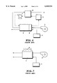
- FIG. 4 is a schematic diagram showing air flow in the fuel cell stack described in Example 2 of the solid polymer electrolyte fuel cell of the present invention
- FIG. 5 is an exploded perspective view showing the basic structure of a cell of a solid polymer electrolyte fuel cell that is generally used;
- FIG. 6 is a basic system diagram showing conventional examples of a reactive gas system and a cooling water system in a solid polymer electrolyte fuel cell;
- FIG. 7 is a basic system diagram of another conventional example of a reactive gas system in a solid polymer electrolyte fuel cell.
- air is flows through an air cooling gas flow path provided in a fuel cell stack to cool the stack, and then flows through an air reactive gas flow path to bring about an electrochemical reaction.
- the stack can be further miniaturized with high cooling efficiency since the air cooling gas flow path is disposed in the fuel cell stack, which is cooled by air cooling.
- liquid or atomized water contained in the air receives heat from the stack during the passage of air through the air cooling gas flow path to be partly or wholly evaporated, whereby the stack is effectively cooled due to the latent heat of evaporation of water while at the same time humidifying air to be sent through the air reactive gas flow path.
- the fuel cell of the present invention is further provided with a circuit wherein condensed water obtained by condensing air flowing through the air reactive gas flow path is added to air to be sent through the air cooling gas flow path for recirculation thereof, or provided with a circuit wherein condensed water obtained by condensing air flowing through the cooling gas flow path for air and containing saturated water vapor is added to air flowing through the air cooling gas flow path for recirculation thereof, or is further provided with a circuit wherein condensed water obtained by condensing air flowing through the air reactive gas flow path is added to air to be sent through the air cooling gas flow path for recirculation thereof, water can be efficiently utilized to make miniaturization of a water feed unit feasible.
- the structure of this Example is constructed in such a way that air fed from an air feed blower 2 and given water by a water feed unit 8 first flows through an air cooling gas flow path 11 formed inside a fuel cell stack 1 to be used for cooling the stack 1, and flows through an air reactive gas flow path 12 inside the stack 1 to be used for a power generation reaction. Further, air discharged from the stack 1 after contribution to the power generation reaction is cooled in a condenser 6A to be stripped of water, and is then discharged from the system. Condensed water obtained in the condenser 6A is recirculated and sent to the water feed unit 8 to be reused as the water combined with the air supplied by air feed blower 2. Fuel gas, supplied by a fuel gas feed unit 3, flows through a fuel gas flow path 13 within fuel cell stack 1.
- the fuel cell stack 1 in use is a stack of having a 1 kW DC output wherein 12 cells having an electrode area of 300 cm 2 are stacked in a laminated form, and which is operated under ordinary pressure at a current density of 0.4 A/cm 2 at a cell voltage of 0.7 V.
- air containing liquid or atomized water is introduced via a cooled air inlet manifold 14, then flows through the inside of the stack 1 to reach a cooled air outlet manifold 15, then sent again to the inside of the stack 1 via a reactive air inlet 16 to contribute as reactive air to a power generation reaction, and then discharged via a reactive air outlet 17.
- a reactive air outlet 16 As shown in the enlarged cross-sectional view of FIG.
- the stack 1 is constructed in such a way that two wavy separators 19 made of a gas-impermeable material are disposed on the two surfaces of every membrane-electrode assembly 18 formed by respectively joining catalyst layers to the two surfaces of a solid polymer electrolyte membrane.
- This forms a fuel gas flow path 13 on the catalyst layer's side of a fuel electrode of the membrane-electrode assembly 18 and an air reactive gas flow path 12 on the catalyst layer's side of an air electrode, while further forming an air cooling gas flow path 11 between the two separators 19 at some distance from membrane-electrode assembly 18.
- the flow rate of reactive air necessary for securing a rated DC output of 1 kW is 6.3 ⁇ 10 -2 m 3 /min when this stack 1 is operated at an air utilization of 40%.
- a temperature difference between cooling air and the cells is set to be 30 K
- the amount of heat consumed for an increase of 30 K in the temperature of air at this flow rate is calculated to be about 40 W, i.e., 11 mW/cm 2 per unit area of electrode.
- the amount of heat of evaporation of water formed through an electrochemical reaction is calculated to be about 90 mW/cm 2 per unit area of electrode.
- the amount of heat necessary for them is 0.1 W/cm 2 , which is insufficient for consumption of heat generated in an amount of 0.31 W/cm 2 in the stack 1.
- the hydraulic diameter of the air cooling gas flow path 11 is, for example, 1 mm in this structure, the temperature difference between cooled air and the cells is 30 K, the Nusselt number is 3.6 and the heat conductivity of air is 27.5 ⁇ 10 -3 W/mK, the cooling power per unit area is evaluated to be about 0.3 W/cm 2 . Since the amount of generated heat is 0.31 W/cm 2 as mentioned above, the cooling power becomes substantially equal to the amount of generated heat.
- the actually secured cooling power is restricted to a lower value.
- a difficulty is encountered in maintaining the stack at a predetermined temperature by removing 0.31 W/cm 2 of heat generated in the stack 1 only with cooling air flowing through the air cooling gas flow path 11.
- This structure is capable of efficiently cooling the stack even without using a large-sized system such as a conventional cooling water system.
- This enables a lightweight and inexpensive solid polymer electrolyte fuel cell to be obtained.
- a further increase in the amount of water to be added to air from the water feed unit 8 can improve the cooling power thereby coping with a fuel cell having a high output density.
- FIG. 4 is a schematic diagram showing air flow in the fuel cell stack of another embodiment of the solid polymer electrolyte fuel cell of the present invention.
- the structure of a reactive gas system of this Example is basically the same as the reactive gas system of Example 1 as shown in FIG. 1 excepting the stack portion.
- Air fed by an air feed blower is admixed with water using a water feed unit, and sent through an air cooling gas flow path disposed inside the stack to cool the stack. Thereafter, the resulting air flows through a reactive gas flow path disposed inside the stack to be used for a power generation reaction.
- Water contained in the air discharged from the stack after contribution to the power generation reaction is condensed in a condenser, and sent to a water feed unit to be reused as the water combined with air supplied by the air feedblower.
- Example 1 A difference between this Example and Example 1 lies in the structure of the air flow path in the stack.
- cooled air containing liquid or atomized water and sent to a cooling air inlet manifold 14A for the fuel cell stack 1A flows through an air cooling gas flow path to absorb heat generated by an electrochemical reaction to thereby cool the stack 1A, while air is heated and elevated in temperature.
- part of the water is evaporated to humidify air, while the rest of the water is condensed in a cooling air outlet manifold 15A to be stored in a liquid form.
- Humidified air is guided to an air reactive gas flow path via a feed inlet provided in the cooling air outlet manifold 15A.
- air is discharged as air exhaust gas from the stack 1A and sent to a condenser disposed in the rear of the stack.
- condensed water stored in the cooling air inlet manifold 15A is sent by means of a pump 24 to the cooling air inlet manifold 14A, from which the condensed water flows again together with introduced cooling air through the air cooling gas flow path to be reused for cooling of the stack 1A and humidification of the reactive air.
- the temperature of the stack 1A is adjusted by the flow rate of the introduced cooling air.
- the degree of humidification of the reactive gas is automatically adjusted by the saturated vapor pressure inside the cooling air outlet manifold 15A, i.e., the temperature of the stack 1A.
- the solid polymer electrolyte fuel cell thereof is constituted in the foregoing manner, the stack can be cooled according to a compact system high in cooling efficiency wherein the latent heat of evaporation of water is efficiently utilized. Accordingly, there can be obtained a lightweight and inexpensive solid polymer electrolyte fuel cell capable of coping with a high output density. Further, since water is so efficiently utilized that a water feed unit can be miniaturized, the solid polymer electrolyte fuel cell can favorably be lightweight, inexpensive and capable of coping with a high output density.
Abstract
Description
Claims (8)
Applications Claiming Priority (2)
| Application Number | Priority Date | Filing Date | Title |
|---|---|---|---|
| JP9-049954 | 1997-03-05 | ||
| JP09049954A JP3077618B2 (en) | 1997-03-05 | 1997-03-05 | Solid polymer electrolyte fuel cell |
Publications (1)
| Publication Number | Publication Date |
|---|---|
| US6045934A true US6045934A (en) | 2000-04-04 |
Family
ID=12845441
Family Applications (1)
| Application Number | Title | Priority Date | Filing Date |
|---|---|---|---|
| US09/034,207 Expired - Fee Related US6045934A (en) | 1997-03-05 | 1998-03-04 | Solid polymer electrolyte fuel cell |
Country Status (3)
| Country | Link |
|---|---|
| US (1) | US6045934A (en) |
| JP (1) | JP3077618B2 (en) |
| DE (1) | DE19809575A1 (en) |
Cited By (44)
| Publication number | Priority date | Publication date | Assignee | Title |
|---|---|---|---|---|
| WO2002011224A2 (en) * | 2000-07-28 | 2002-02-07 | Hydrogenics Corporation | Method and apparatus for humidification and temperature control of incoming fuel cell process gas |
| WO2002011221A2 (en) * | 2000-07-28 | 2002-02-07 | Proton Motor Fuel Cell Gmbh | Device and method for wetting polymer electrolyte membrane fuel cells |
| US6383677B1 (en) | 1999-10-07 | 2002-05-07 | Allen Engineering Company, Inc. | Fuel cell current collector |
| US6387556B1 (en) | 1997-11-20 | 2002-05-14 | Avista Laboratories, Inc. | Fuel cell power systems and methods of controlling a fuel cell power system |
| US6428918B1 (en) | 2000-04-07 | 2002-08-06 | Avista Laboratories, Inc. | Fuel cell power systems, direct current voltage converters, fuel cell power generation methods, power conditioning methods and direct current power conditioning methods |
| WO2002061867A2 (en) * | 2001-01-31 | 2002-08-08 | Viessmann Werke Gmbh & Co. | Fuel cells with integrated humidification and method for humidifying fuel cell process gas |
| US20020127454A1 (en) * | 2000-06-02 | 2002-09-12 | Subhash Narang | Polymer composition |
| US20020150802A1 (en) * | 2001-04-11 | 2002-10-17 | Tomonori Imamura | Fuel cell system |
| US6468682B1 (en) | 2000-05-17 | 2002-10-22 | Avista Laboratories, Inc. | Ion exchange membrane fuel cell |
| US20020197522A1 (en) * | 2001-06-01 | 2002-12-26 | Craig Lawrence | Fuel cell assembly for portable electronic device and interface, control, and regulator circuit for fuel cell powered electronic device |
| FR2828011A1 (en) * | 2001-07-26 | 2003-01-31 | Air Liquide | Supplying air to cathode of fuel cell, comprises use of input/output heat exchanger with water attracting lining in output circuit and pump to add collected water to input |
| US6514634B1 (en) | 2000-09-29 | 2003-02-04 | Plug Power Inc. | Method and system for humidification of a fuel |
| US20030039875A1 (en) * | 2001-08-21 | 2003-02-27 | Munehisa Horiguchi | Fuel cell |
| EP1313161A1 (en) * | 2001-11-15 | 2003-05-21 | Ballard Power Systems AG | Fuel cell system and method for operating the same |
| US6576357B1 (en) * | 1998-05-14 | 2003-06-10 | Siemens Aktiengesellschaft | Polymer electrolyte membrane fuel cell system and method for wetting and/or cooling a fuel cell stack |
| US6602626B1 (en) | 2000-02-16 | 2003-08-05 | Gencell Corporation | Fuel cell with internal thermally integrated autothermal reformer |
| US6632555B2 (en) * | 2001-05-18 | 2003-10-14 | Ballard Power Systems Inc. | Proton electrolyte membrane fuel cell with anti-freeze coolant and humidifiers |
| US6670062B2 (en) | 2001-05-31 | 2003-12-30 | Plug Power Inc. | Methods and systems for humidifying fuel for use in fuel processors and fuel cell systems |
| US6670069B2 (en) | 2000-03-17 | 2003-12-30 | Gencell Corporation | Fuel cell stack assembly |
| US20040013927A1 (en) * | 2001-06-01 | 2004-01-22 | Craig Lawrence | Fuel cell assembly for portable electronic device and interface, control, and regulator circuit for fuel cell powered electronic device |
| US20040028953A1 (en) * | 1999-06-17 | 2004-02-12 | Saint-Gobain Vitrage | Laminated glazing which reflects solar rays and heat rays |
| US20040096719A1 (en) * | 2002-08-07 | 2004-05-20 | Prabhakar Singh | Passive vapor exchange systems and techniques for fuel reforming and prevention of carbon fouling |
| US20040126666A1 (en) * | 2002-05-13 | 2004-07-01 | Shuguang Cao | Ion conductive block copolymers |
| US20040146769A1 (en) * | 2002-12-02 | 2004-07-29 | Michael Birschbach | Fuel cell cartridge for portable electronic device |
| US20040151975A1 (en) * | 1999-11-16 | 2004-08-05 | Allen Jeffrey P. | Fuel cell bipolar separator plate and current collector assembly and method of manufacture |
| US6772617B1 (en) | 2003-01-24 | 2004-08-10 | Gencell Corporation | Method and apparatus for in-situ leveling of progressively formed sheet metal |
| US6787254B2 (en) | 2000-07-28 | 2004-09-07 | Hydrogenics Corporation | Method and apparatus for humidification and temperature control of incoming fuel cell process gas |
| US20040175598A1 (en) * | 2002-12-02 | 2004-09-09 | Bliven David C. | Fuel cell power supply for portable computing device and method for fuel cell power control |
| WO2004102712A2 (en) * | 2003-05-16 | 2004-11-25 | Toyota Jidosha Kabushiki Kaisha | Fuel cell |
| EP1498971A2 (en) * | 2003-07-14 | 2005-01-19 | Asia Pacific Fuel Cell Technologies, Ltd. | Cooling of air-cooled fuel cell system |
| US20050142409A1 (en) * | 2003-12-12 | 2005-06-30 | Cho Tae-Hee | Fuel cell system and control method thereof |
| US20050181256A1 (en) * | 2002-05-13 | 2005-08-18 | Shuguang Cao | Ion conductive random copolymers |
| US20060141333A1 (en) * | 2004-12-22 | 2006-06-29 | Samsung Sdi Co., Ltd. | Metallic separator for fuel cell and fuel cell including the same |
| US20060154125A1 (en) * | 2005-01-10 | 2006-07-13 | Young-Seung Na | Stack for fuel cell and fuel cell system with the same |
| US20070087240A1 (en) * | 2005-10-18 | 2007-04-19 | General Hydrogen Corporation | Fuel cell fluid dissipater |
| US7238451B2 (en) | 2000-12-29 | 2007-07-03 | The Board Of Regents Of The University Of Oklahoma | Conductive polyamine-based electrolyte |
| US20080229606A1 (en) * | 2004-04-23 | 2008-09-25 | Toshihisa Hirai | Heating Blower with Electrostatic Atomizing Device |
| US20090214915A1 (en) * | 2008-02-25 | 2009-08-27 | Hyundai Motor Company | Fuel cell system using evaporative cooling and method of cooling fuel cell system |
| US20100304261A1 (en) * | 2005-04-22 | 2010-12-02 | Gm Global Technology Operations, Inc. | Fuel cell design with an integrated heat exchanger and gas humidification unit |
| CN102085802A (en) * | 2009-12-03 | 2011-06-08 | 现代自动车株式会社 | Cooling system for eco-friendly vehicle |
| US20110132030A1 (en) * | 2009-12-03 | 2011-06-09 | Hyundai Motor Company | Integrated Cooling System for Eco-Friendly Vehicle |
| US20120088173A1 (en) * | 2009-07-16 | 2012-04-12 | Darling Robert M | Variable air utilization increases fuel cell membrane durability |
| US9991501B2 (en) | 2015-01-05 | 2018-06-05 | Johnson Controls Technology Company | Vent shield for a battery module |
| WO2023239965A3 (en) * | 2022-06-10 | 2024-02-08 | Zeroavia Ltd | Turbo-evaporative cooled ht-pem fuel-cell system |
Families Citing this family (26)
| Publication number | Priority date | Publication date | Assignee | Title |
|---|---|---|---|---|
| JP3443276B2 (en) * | 1997-05-14 | 2003-09-02 | 三洋電機株式会社 | Fuel cell system |
| JP4543440B2 (en) | 1997-12-22 | 2010-09-15 | 株式会社エクォス・リサーチ | Water direct injection fuel cell system |
| JPH11317236A (en) | 1997-12-22 | 1999-11-16 | Aqueous Reserch:Kk | Fuel cell system |
| JP4131038B2 (en) | 1998-06-26 | 2008-08-13 | 株式会社エクォス・リサーチ | Fuel cell system |
| DE19917812C2 (en) * | 1999-04-20 | 2002-11-21 | Siemens Ag | Membrane electrode unit for a self-moistening fuel cell, method for its production and fuel cell battery with such a membrane electrode unit |
| US6331366B1 (en) * | 1999-06-23 | 2001-12-18 | International Fuel Cells Llc | Operating system for a fuel cell power plant |
| DE19953404B4 (en) * | 1999-11-06 | 2004-11-25 | Daimlerchrysler Ag | Electrochemical fuel cell stack |
| JP4686814B2 (en) | 1999-11-17 | 2011-05-25 | 株式会社エクォス・リサーチ | Fuel cell device |
| DE10006472A1 (en) | 2000-02-14 | 2001-08-23 | Siemens Ag | Fuel cell block |
| JP4934938B2 (en) * | 2002-02-12 | 2012-05-23 | 株式会社エクォス・リサーチ | Fuel cell separator |
| JP4839565B2 (en) * | 2002-12-12 | 2011-12-21 | ソニー株式会社 | Fuel cell system |
| JP4586331B2 (en) * | 2003-03-24 | 2010-11-24 | 株式会社エクォス・リサーチ | Separator |
| US7314679B2 (en) | 2003-07-15 | 2008-01-01 | Honda Motor Co., Ltd. | Air supply apparatus for a fuel cell |
| JP2005129431A (en) * | 2003-10-27 | 2005-05-19 | Toyota Motor Corp | Fuel cell and gas separator for fuel cell |
| JP2005209470A (en) | 2004-01-22 | 2005-08-04 | Equos Research Co Ltd | Fuel cell |
| JP5077730B2 (en) * | 2004-03-02 | 2012-11-21 | トヨタ自動車株式会社 | Fuel cell system |
| JP4955913B2 (en) * | 2004-06-11 | 2012-06-20 | 株式会社豊田中央研究所 | Fuel cell system |
| JP4992188B2 (en) | 2005-03-11 | 2012-08-08 | 株式会社エクォス・リサーチ | Separator unit and fuel cell stack |
| JP4887639B2 (en) | 2005-03-11 | 2012-02-29 | 株式会社エクォス・リサーチ | Separator unit and fuel cell stack |
| JP4810869B2 (en) * | 2005-04-20 | 2011-11-09 | 株式会社エクォス・リサーチ | Fuel cell system |
| CN100449833C (en) * | 2005-08-26 | 2009-01-07 | 比亚迪股份有限公司 | Flow field plate for fuel battery |
| JP2007257991A (en) * | 2006-03-23 | 2007-10-04 | Equos Research Co Ltd | Fuel cell system |
| JP5145680B2 (en) * | 2006-09-28 | 2013-02-20 | 株式会社日立製作所 | Fuel cell separator |
| JP4553004B2 (en) * | 2007-12-14 | 2010-09-29 | 株式会社エクォス・リサーチ | Fuel cell stack |
| JP2016038973A (en) * | 2014-08-06 | 2016-03-22 | トヨタ自動車株式会社 | Fuel battery system and control method for the same |
| KR101838510B1 (en) | 2016-03-11 | 2018-03-14 | 현대자동차주식회사 | Evaporative cooling type fuel cell system and stack colling control method for the same |
Citations (4)
| Publication number | Priority date | Publication date | Assignee | Title |
|---|---|---|---|---|
| US5360679A (en) * | 1993-08-20 | 1994-11-01 | Ballard Power Systems Inc. | Hydrocarbon fueled solid polymer fuel cell electric power generation system |
| US5441821A (en) * | 1994-12-23 | 1995-08-15 | Ballard Power Systems Inc. | Electrochemical fuel cell system with a regulated vacuum ejector for recirculation of the fluid fuel stream |
| US5470671A (en) * | 1993-12-22 | 1995-11-28 | Ballard Power Systems Inc. | Electrochemical fuel cell employing ambient air as the oxidant and coolant |
| US5786104A (en) * | 1996-12-31 | 1998-07-28 | The Dow Chemical Company | Method and apparatus for humidification of incoming fuel cell process gases |
-
1997
- 1997-03-05 JP JP09049954A patent/JP3077618B2/en not_active Expired - Fee Related
-
1998
- 1998-03-04 US US09/034,207 patent/US6045934A/en not_active Expired - Fee Related
- 1998-03-05 DE DE19809575A patent/DE19809575A1/en not_active Withdrawn
Patent Citations (4)
| Publication number | Priority date | Publication date | Assignee | Title |
|---|---|---|---|---|
| US5360679A (en) * | 1993-08-20 | 1994-11-01 | Ballard Power Systems Inc. | Hydrocarbon fueled solid polymer fuel cell electric power generation system |
| US5470671A (en) * | 1993-12-22 | 1995-11-28 | Ballard Power Systems Inc. | Electrochemical fuel cell employing ambient air as the oxidant and coolant |
| US5441821A (en) * | 1994-12-23 | 1995-08-15 | Ballard Power Systems Inc. | Electrochemical fuel cell system with a regulated vacuum ejector for recirculation of the fluid fuel stream |
| US5786104A (en) * | 1996-12-31 | 1998-07-28 | The Dow Chemical Company | Method and apparatus for humidification of incoming fuel cell process gases |
Cited By (73)
| Publication number | Priority date | Publication date | Assignee | Title |
|---|---|---|---|---|
| US6387556B1 (en) | 1997-11-20 | 2002-05-14 | Avista Laboratories, Inc. | Fuel cell power systems and methods of controlling a fuel cell power system |
| US6576357B1 (en) * | 1998-05-14 | 2003-06-10 | Siemens Aktiengesellschaft | Polymer electrolyte membrane fuel cell system and method for wetting and/or cooling a fuel cell stack |
| US20040028953A1 (en) * | 1999-06-17 | 2004-02-12 | Saint-Gobain Vitrage | Laminated glazing which reflects solar rays and heat rays |
| US6383677B1 (en) | 1999-10-07 | 2002-05-07 | Allen Engineering Company, Inc. | Fuel cell current collector |
| US6855447B2 (en) | 1999-10-07 | 2005-02-15 | Gencell Corporation | Fuel cell current collector |
| US20040151975A1 (en) * | 1999-11-16 | 2004-08-05 | Allen Jeffrey P. | Fuel cell bipolar separator plate and current collector assembly and method of manufacture |
| US6777126B1 (en) | 1999-11-16 | 2004-08-17 | Gencell Corporation | Fuel cell bipolar separator plate and current collector assembly and method of manufacture |
| US7279016B2 (en) | 1999-11-16 | 2007-10-09 | Gencell Corporation | Fuel cell bipolar separator plate and current collector assembly and method of manufacture |
| US6602626B1 (en) | 2000-02-16 | 2003-08-05 | Gencell Corporation | Fuel cell with internal thermally integrated autothermal reformer |
| US6670069B2 (en) | 2000-03-17 | 2003-12-30 | Gencell Corporation | Fuel cell stack assembly |
| US6428918B1 (en) | 2000-04-07 | 2002-08-06 | Avista Laboratories, Inc. | Fuel cell power systems, direct current voltage converters, fuel cell power generation methods, power conditioning methods and direct current power conditioning methods |
| US6468682B1 (en) | 2000-05-17 | 2002-10-22 | Avista Laboratories, Inc. | Ion exchange membrane fuel cell |
| US6743536B2 (en) | 2000-05-17 | 2004-06-01 | Relion, Inc. | Fuel cell power system and method of controlling a fuel cell power system |
| US20020127454A1 (en) * | 2000-06-02 | 2002-09-12 | Subhash Narang | Polymer composition |
| WO2002011224A3 (en) * | 2000-07-28 | 2002-09-26 | Hydrogenics Corp | Method and apparatus for humidification and temperature control of incoming fuel cell process gas |
| US7261150B2 (en) | 2000-07-28 | 2007-08-28 | Hydrogenics Corporation | Apparatus for humidification and temperature control of incoming fuel cell process gas |
| WO2002011221A2 (en) * | 2000-07-28 | 2002-02-07 | Proton Motor Fuel Cell Gmbh | Device and method for wetting polymer electrolyte membrane fuel cells |
| US6787254B2 (en) | 2000-07-28 | 2004-09-07 | Hydrogenics Corporation | Method and apparatus for humidification and temperature control of incoming fuel cell process gas |
| WO2002011224A2 (en) * | 2000-07-28 | 2002-02-07 | Hydrogenics Corporation | Method and apparatus for humidification and temperature control of incoming fuel cell process gas |
| US7052791B2 (en) | 2000-07-28 | 2006-05-30 | Hydrogenics Corporation | Apparatus for humidification and temperature control of incoming fuel cell process gas |
| US7051801B1 (en) | 2000-07-28 | 2006-05-30 | Hydrogenics Corporation | Method and apparatus for humidification and temperature control of incoming fuel cell process gas |
| WO2002011221A3 (en) * | 2000-07-28 | 2003-01-23 | Proton Motor Fuel Cell Gmbh | Device and method for wetting polymer electrolyte membrane fuel cells |
| US6514634B1 (en) | 2000-09-29 | 2003-02-04 | Plug Power Inc. | Method and system for humidification of a fuel |
| US7238451B2 (en) | 2000-12-29 | 2007-07-03 | The Board Of Regents Of The University Of Oklahoma | Conductive polyamine-based electrolyte |
| WO2002061867A2 (en) * | 2001-01-31 | 2002-08-08 | Viessmann Werke Gmbh & Co. | Fuel cells with integrated humidification and method for humidifying fuel cell process gas |
| WO2002061867A3 (en) * | 2001-01-31 | 2003-06-12 | Viessmann Werke Kg | Fuel cells with integrated humidification and method for humidifying fuel cell process gas |
| US20020150802A1 (en) * | 2001-04-11 | 2002-10-17 | Tomonori Imamura | Fuel cell system |
| US6790550B2 (en) | 2001-04-11 | 2004-09-14 | Denso Corporation | Water control for a fuel cell system |
| US6632555B2 (en) * | 2001-05-18 | 2003-10-14 | Ballard Power Systems Inc. | Proton electrolyte membrane fuel cell with anti-freeze coolant and humidifiers |
| US6670062B2 (en) | 2001-05-31 | 2003-12-30 | Plug Power Inc. | Methods and systems for humidifying fuel for use in fuel processors and fuel cell systems |
| US20040013927A1 (en) * | 2001-06-01 | 2004-01-22 | Craig Lawrence | Fuel cell assembly for portable electronic device and interface, control, and regulator circuit for fuel cell powered electronic device |
| US20020197522A1 (en) * | 2001-06-01 | 2002-12-26 | Craig Lawrence | Fuel cell assembly for portable electronic device and interface, control, and regulator circuit for fuel cell powered electronic device |
| FR2828011A1 (en) * | 2001-07-26 | 2003-01-31 | Air Liquide | Supplying air to cathode of fuel cell, comprises use of input/output heat exchanger with water attracting lining in output circuit and pump to add collected water to input |
| US7153605B2 (en) | 2001-08-21 | 2006-12-26 | Kabushikikaisha Equos Research | Fuel cell cooled by latent heat of water evaporation |
| US20030039875A1 (en) * | 2001-08-21 | 2003-02-27 | Munehisa Horiguchi | Fuel cell |
| EP1313161A1 (en) * | 2001-11-15 | 2003-05-21 | Ballard Power Systems AG | Fuel cell system and method for operating the same |
| US20040126666A1 (en) * | 2002-05-13 | 2004-07-01 | Shuguang Cao | Ion conductive block copolymers |
| US20050181256A1 (en) * | 2002-05-13 | 2005-08-18 | Shuguang Cao | Ion conductive random copolymers |
| US20040096719A1 (en) * | 2002-08-07 | 2004-05-20 | Prabhakar Singh | Passive vapor exchange systems and techniques for fuel reforming and prevention of carbon fouling |
| US20040146769A1 (en) * | 2002-12-02 | 2004-07-29 | Michael Birschbach | Fuel cell cartridge for portable electronic device |
| US20040175598A1 (en) * | 2002-12-02 | 2004-09-09 | Bliven David C. | Fuel cell power supply for portable computing device and method for fuel cell power control |
| US6772617B1 (en) | 2003-01-24 | 2004-08-10 | Gencell Corporation | Method and apparatus for in-situ leveling of progressively formed sheet metal |
| WO2004102712A3 (en) * | 2003-05-16 | 2005-02-17 | Toyota Motor Co Ltd | Fuel cell |
| US7923169B2 (en) | 2003-05-16 | 2011-04-12 | Toyota Jidosha Kabushiki Kaisha | Self-sealing fuel cell separator |
| US20070207365A1 (en) * | 2003-05-16 | 2007-09-06 | Toyota Jidosha Kabushiki Kaisha | Fuel Cell |
| WO2004102712A2 (en) * | 2003-05-16 | 2004-11-25 | Toyota Jidosha Kabushiki Kaisha | Fuel cell |
| CN100355136C (en) * | 2003-05-16 | 2007-12-12 | 丰田自动车株式会社 | Fuel cell |
| EP1498971A3 (en) * | 2003-07-14 | 2007-01-03 | Asia Pacific Fuel Cell Technologies, Ltd. | Cooling of air-cooled fuel cell system |
| EP1498971A2 (en) * | 2003-07-14 | 2005-01-19 | Asia Pacific Fuel Cell Technologies, Ltd. | Cooling of air-cooled fuel cell system |
| US20050142409A1 (en) * | 2003-12-12 | 2005-06-30 | Cho Tae-Hee | Fuel cell system and control method thereof |
| US20080229606A1 (en) * | 2004-04-23 | 2008-09-25 | Toshihisa Hirai | Heating Blower with Electrostatic Atomizing Device |
| US8015724B2 (en) * | 2004-04-23 | 2011-09-13 | Panasonic Electric Works Co., Ltd. | Heating blower with electrostatic atomizing device |
| US7947409B2 (en) * | 2004-12-22 | 2011-05-24 | Samsung Sdi Co., Ltd. | Metallic separator for fuel cell and fuel cell including the same |
| US20060141333A1 (en) * | 2004-12-22 | 2006-06-29 | Samsung Sdi Co., Ltd. | Metallic separator for fuel cell and fuel cell including the same |
| US20060154125A1 (en) * | 2005-01-10 | 2006-07-13 | Young-Seung Na | Stack for fuel cell and fuel cell system with the same |
| US8568937B2 (en) * | 2005-04-22 | 2013-10-29 | GM Global Technology Operations LLC | Fuel cell design with an integrated heat exchanger and gas humidification unit |
| US20100304261A1 (en) * | 2005-04-22 | 2010-12-02 | Gm Global Technology Operations, Inc. | Fuel cell design with an integrated heat exchanger and gas humidification unit |
| US20070087240A1 (en) * | 2005-10-18 | 2007-04-19 | General Hydrogen Corporation | Fuel cell fluid dissipater |
| KR100986525B1 (en) | 2008-02-25 | 2010-10-07 | 현대자동차주식회사 | Evaporative cooling type fuel cell system and stack cooling method for the same |
| US20090214915A1 (en) * | 2008-02-25 | 2009-08-27 | Hyundai Motor Company | Fuel cell system using evaporative cooling and method of cooling fuel cell system |
| US8216736B2 (en) * | 2008-02-25 | 2012-07-10 | Hyundai Motor Company | Fuel cell system using evaporative cooling method |
| CN101521287B (en) * | 2008-02-25 | 2013-05-22 | 现代自动车株式会社 | Evaporative cooling type fuel cell system and stack cooling method for the same |
| US9029031B2 (en) * | 2009-07-16 | 2015-05-12 | Ballard Power Systems Inc. | Variable air utilization increases fuel cell membrane durability |
| US20120088173A1 (en) * | 2009-07-16 | 2012-04-12 | Darling Robert M | Variable air utilization increases fuel cell membrane durability |
| CN102085802A (en) * | 2009-12-03 | 2011-06-08 | 现代自动车株式会社 | Cooling system for eco-friendly vehicle |
| US20110132030A1 (en) * | 2009-12-03 | 2011-06-09 | Hyundai Motor Company | Integrated Cooling System for Eco-Friendly Vehicle |
| US9180753B2 (en) | 2009-12-03 | 2015-11-10 | Hyundai Motor Company | Integrated cooling system for eco-friendly vehicle |
| CN102085802B (en) * | 2009-12-03 | 2015-11-25 | 现代自动车株式会社 | For the cooling system of Eco-friendly vehicle |
| US9385385B2 (en) | 2009-12-03 | 2016-07-05 | Hyundai Motor Company | Cooling system for eco-friendly vehicle |
| US9815349B2 (en) | 2009-12-03 | 2017-11-14 | Hyundai Motor Company | Integrated cooling system for eco-friendly vehicle |
| US9991501B2 (en) | 2015-01-05 | 2018-06-05 | Johnson Controls Technology Company | Vent shield for a battery module |
| US10847777B2 (en) | 2015-01-05 | 2020-11-24 | Cps Technology Holdings Llc | Vent shield for a battery module |
| WO2023239965A3 (en) * | 2022-06-10 | 2024-02-08 | Zeroavia Ltd | Turbo-evaporative cooled ht-pem fuel-cell system |
Also Published As
| Publication number | Publication date |
|---|---|
| DE19809575A1 (en) | 1998-09-10 |
| JPH10247505A (en) | 1998-09-14 |
| JP3077618B2 (en) | 2000-08-14 |
Similar Documents
| Publication | Publication Date | Title |
|---|---|---|
| US6045934A (en) | Solid polymer electrolyte fuel cell | |
| JP3203150B2 (en) | Polymer electrolyte fuel cell and polymer electrolyte fuel cell system | |
| JP3530793B2 (en) | Fuel cell and operating method thereof | |
| US8304123B2 (en) | Ambient pressure fuel cell system employing partial air humidification | |
| JP3706937B2 (en) | Fuel cell system | |
| JPH06338338A (en) | Humidification of high polymer ion exchange film of fuel cell | |
| JPH06325780A (en) | Fuel cell system | |
| JP3389551B2 (en) | Polymer electrolyte fuel cell | |
| JP2004031135A (en) | Fuel cell and its control method | |
| US8697298B2 (en) | Fuel cell system with heater | |
| JP3510285B2 (en) | Solid polymer electrolyte fuel cell system | |
| JPH09283162A (en) | Solid high molecular fuel cell | |
| JP2002170584A (en) | Solid polymer type fuel battery | |
| JP3111682B2 (en) | Solid polymer electrolyte fuel cell system | |
| JPH06333583A (en) | Solid polyelectrolyte fuel cell generating device | |
| JP2914898B2 (en) | Polymer electrolyte fuel cell system | |
| US7090941B2 (en) | Fuel cell stack and a method of supplying reactant gases to the fuel cell stack | |
| JP2000277128A (en) | Solid polymer type fuel cell | |
| JP4665353B2 (en) | Solid polymer electrolyte fuel cell power generator and its operation method | |
| JPH08306375A (en) | Solid polymer type fuel sell | |
| JP2008059874A (en) | Fuel cell stack | |
| JP4000971B2 (en) | Fuel cell system | |
| JP4553004B2 (en) | Fuel cell stack | |
| JPH06338332A (en) | Gas separator for solid high molecular electrolytic fuel cell | |
| JP3981476B2 (en) | Fuel cell stack |
Legal Events
| Date | Code | Title | Description |
|---|---|---|---|
| AS | Assignment |
Owner name: FUJI ELECTRIC CO., LTD., JAPAN Free format text: ASSIGNMENT OF ASSIGNORS INTEREST;ASSIGNOR:ENAMI, YOSHIAKI;REEL/FRAME:009380/0512 Effective date: 19980520 |
|
| FEPP | Fee payment procedure |
Free format text: PAYOR NUMBER ASSIGNED (ORIGINAL EVENT CODE: ASPN); ENTITY STATUS OF PATENT OWNER: LARGE ENTITY |
|
| FPAY | Fee payment |
Year of fee payment: 4 |
|
| FPAY | Fee payment |
Year of fee payment: 8 |
|
| REMI | Maintenance fee reminder mailed | ||
| LAPS | Lapse for failure to pay maintenance fees | ||
| STCH | Information on status: patent discontinuation |
Free format text: PATENT EXPIRED DUE TO NONPAYMENT OF MAINTENANCE FEES UNDER 37 CFR 1.362 |
|
| FP | Lapsed due to failure to pay maintenance fee |
Effective date: 20120404 |