US6044899A - Low EMI emissions heat sink device - Google Patents
Low EMI emissions heat sink device Download PDFInfo
- Publication number
- US6044899A US6044899A US09/067,248 US6724898A US6044899A US 6044899 A US6044899 A US 6044899A US 6724898 A US6724898 A US 6724898A US 6044899 A US6044899 A US 6044899A
- Authority
- US
- United States
- Prior art keywords
- heat sink
- heat
- integrated circuit
- circuit package
- electronic chassis
- Prior art date
- Legal status (The legal status is an assumption and is not a legal conclusion. Google has not performed a legal analysis and makes no representation as to the accuracy of the status listed.)
- Expired - Fee Related
Links
Images


Classifications
-
- H—ELECTRICITY
- H05—ELECTRIC TECHNIQUES NOT OTHERWISE PROVIDED FOR
- H05K—PRINTED CIRCUITS; CASINGS OR CONSTRUCTIONAL DETAILS OF ELECTRIC APPARATUS; MANUFACTURE OF ASSEMBLAGES OF ELECTRICAL COMPONENTS
- H05K9/00—Screening of apparatus or components against electric or magnetic fields
- H05K9/0007—Casings
- H05K9/002—Casings with localised screening
- H05K9/0022—Casings with localised screening of components mounted on printed circuit boards [PCB]
-
- H—ELECTRICITY
- H01—ELECTRIC ELEMENTS
- H01L—SEMICONDUCTOR DEVICES NOT COVERED BY CLASS H10
- H01L23/00—Details of semiconductor or other solid state devices
- H01L23/34—Arrangements for cooling, heating, ventilating or temperature compensation ; Temperature sensing arrangements
- H01L23/36—Selection of materials, or shaping, to facilitate cooling or heating, e.g. heatsinks
- H01L23/367—Cooling facilitated by shape of device
- H01L23/3675—Cooling facilitated by shape of device characterised by the shape of the housing
-
- H—ELECTRICITY
- H01—ELECTRIC ELEMENTS
- H01L—SEMICONDUCTOR DEVICES NOT COVERED BY CLASS H10
- H01L23/00—Details of semiconductor or other solid state devices
- H01L23/34—Arrangements for cooling, heating, ventilating or temperature compensation ; Temperature sensing arrangements
- H01L23/36—Selection of materials, or shaping, to facilitate cooling or heating, e.g. heatsinks
- H01L23/373—Cooling facilitated by selection of materials for the device or materials for thermal expansion adaptation, e.g. carbon
- H01L23/3736—Metallic materials
-
- H—ELECTRICITY
- H01—ELECTRIC ELEMENTS
- H01L—SEMICONDUCTOR DEVICES NOT COVERED BY CLASS H10
- H01L23/00—Details of semiconductor or other solid state devices
- H01L23/552—Protection against radiation, e.g. light or electromagnetic waves
-
- H—ELECTRICITY
- H05—ELECTRIC TECHNIQUES NOT OTHERWISE PROVIDED FOR
- H05K—PRINTED CIRCUITS; CASINGS OR CONSTRUCTIONAL DETAILS OF ELECTRIC APPARATUS; MANUFACTURE OF ASSEMBLAGES OF ELECTRICAL COMPONENTS
- H05K9/00—Screening of apparatus or components against electric or magnetic fields
- H05K9/0007—Casings
- H05K9/0018—Casings with provisions to reduce aperture leakages in walls, e.g. terminals, connectors, cables
-
- H—ELECTRICITY
- H01—ELECTRIC ELEMENTS
- H01L—SEMICONDUCTOR DEVICES NOT COVERED BY CLASS H10
- H01L2924/00—Indexing scheme for arrangements or methods for connecting or disconnecting semiconductor or solid-state bodies as covered by H01L24/00
- H01L2924/0001—Technical content checked by a classifier
- H01L2924/0002—Not covered by any one of groups H01L24/00, H01L24/00 and H01L2224/00
-
- H—ELECTRICITY
- H01—ELECTRIC ELEMENTS
- H01L—SEMICONDUCTOR DEVICES NOT COVERED BY CLASS H10
- H01L2924/00—Indexing scheme for arrangements or methods for connecting or disconnecting semiconductor or solid-state bodies as covered by H01L24/00
- H01L2924/30—Technical effects
- H01L2924/301—Electrical effects
- H01L2924/3011—Impedance
Definitions
- the present invention relates generally to the field of integrated circuit heat dissipation and more particularly to heat sinks.
- this invention provides a heat sink with elecro-magnetic radiation interference shielding.
- a board mounted electronic component may be in the form of an integrated circuit or a chip.
- the tendency in modern design is for integrated circuits or chips to become smaller and faster in operation. A problem which exists with faster operation of smaller circuits is that they tend to increase in temperature and may overheat to such a degree that permanent damage may result unless steps are taken to avoid such situations.
- heat removal becomes a prime necessity.
- heat removal considerations may be contradictory to the considerations necessary for overcoming electromagnetic emission problems. This is because for the avoidance of EMI emissions, a surrounding shield is normally necessary for an integrated circuit and this detracts from the removal of heat because such a shield tends to act as a heat insulator.
- heat sinks are mounted to an outer surface of an integrated circuit package to facilitate the removal of heat from the integrated circuit contained therein.
- Most heat sinks are thermally conductive and have a plurality of fins to provide a large surface area, which allows heat to be more efficiently dissipated by natural or forced air flow.
- heat sinks transfer heat from the integrated circuit to the air inside the computer chassis by means of convection. This increases the overall temperature within the computer chassis.
- fans are also used in conjunction with heat sinks to increase the rate of heat dissipation. Fans may be arranged to direct heat from inside the computer chassis towards holes in the computer chassis, thus moving hot air to the outside of the computer chassis. These fans are generally very noisy, consume power and take-up space inside the electronic chassis.
- the above and other aspects of the present invention may be accomplished in a low EMI emissions heat sink device that dissipates heat away from an IC package by means of conduction to the top, sides and bottom of the electronic chassis.
- the heat sink of the present invention may also have a ferrite ring to reduce EMI emissions from the IC package.
- the heat sink of the present invention may also have fins that are outside of the electronic chassis for greater heat dissipation without the use of a fan.
- FIG. 1 shows a cross-sectional view of a low EMI emissions heat sink according to a first embodiment of the present invention
- FIG. 2 shows a cross-sectional view of a low EMI emissions heat sink according to a second embodiment of the present invention
- FIG. 3 shows a cross-sectional view of a low EMI emissions heat sink according to a third embodiment of the present invention.
- FIG. 4 shows a blown-up perspective view illustrating how ferrite rings may be attached to a heat sink according to the present invention.
- FIG. 1 illustrates a cross-sectional view of a low EMI emissions heat sink 100 according to a first embodiment of the present invention.
- Heat sink 100 has a narrow midsection 124 and wider first and second end sections 120 and 122. End section 122 sides on top of integrated circuit package 110, which is plugged into socket 106.
- Socket 106 is mounted on a printed circuit board 112, which is mounted to electronic chassis bottom 108 by any known means.
- Top end section 120 is located between locators 116 of the electronic chassis cover 114.
- the electronic chassis may be any known material, but is generally made of steel.
- the heat sink 100 may be made of any known heat sink material, such as aluminum.
- a ferrite ring 102 is attached to the narrow midsection 124 of heat sink 100.
- heat sinks transfer heat to the air inside the chassis via convection.
- heat sink 100 of the present invention is in contact with electronic chassis cover 114, heat from the integrated circuit package is transferred to the chassis via conduction. This permits the air temperature inside the electronic chassis, and the resulting thermal stress on other electronic components to be lower than that which is typical with convective type heat sinks.
- the conduction type heat dissipation also eliminates the need for a fan required in most convective applications. This greatly improves the reliability, lowers the power consumption, and creates a virtually silent computer.
- the heat sink 100 may act as a structural member, further stabilizing the top cover 114 of the electronic chassis, thus creating a simpler, less expensive enclosure.
- the ferrite ring 102 attached to the midsection 124 of heat sink 100 reduces EMI emissions to an acceptable level while still providing good thermal performance. This is accomplished through increased electrical impedance of the EMI transmission path between the integrated circuit package 110 and the electronic chassis, thus reducing the capacitive coupling and RFI concerns that has limited previous attempts at the heat conduction approach.
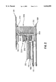
- FIG. 2 illustrates a cross-sectional view of a low EMI emissions heat sink 200 according to a second embodiment of the present invention.
- Heat sink 200 comprises a narrow midsection 203 and first and second wider end sections 210 and 212.
- Heat sink 200 may include heat dissipation fins 206 on at least one side.
- Heat sink 200 may also include a heat pipe 201 that rests on top of integrated circuit package 110 mounted in socket 106 attached to printed circuit board 112, which is attached to electronic chassis bottom 108 by any known means. There may be a thermally conductive compound or elastomer between the integrated circuit package 110 and the heat pipe 201.
- the heat sink 200 may include a tab 204, such that once the ferrite ring 202 is mounted on the heat pipe, the tab 204 is bent, and thus prevents the ferrite ring 202 from sliding along the heat pipe 201.
- the first end 210 of the heat sink 200 is located within locators 116 of the electronic chassis top 114 and the second end 212 is resting on the electronic chassis bottom. Accordingly, the heat sink 200 may provide structural support to the electronic chassis. Moreover, this embodiment will put less mechanical stress on the integrated circuit package 110 than the first embodiment as this heat sink 200 extends between the top and bottom surfaces of the electronic chassis, rather than resting on the top surface of the integrated circuit package 110.
- fins 206 may be located on a side of the heat sink that has some form of air circulation.
- ferrite ring 202 provides electrical impedance of the EMI transmission path between the integrated circuit package 110 and the electronic chassis, thus reducing the capacitive coupling and RFI concerns that have limited heat conduction type heat sinks in the past.
- heat sink 200 may be any known heat sink material, such as aluminum.
- FIG. 3 illustrates a cross-sectional view of a low EMI emissions heat sink 300 according to a third embodiment of the present invention.
- Heat sink 300 is attached to the outside of the electronic chassis along side 304 of the heat sink 300 by any known means, such as screws, rivets, glue, etc.
- Heat pipe 301 extends through hole 310 in the electronic chassis and rests on top of integrated circuit package 110 that is plugged into socket 106 mounted on printed circuit board 112 which is attached to electronic chassis bottom 108 by any known means. There may be a thermally conductive compound or elastomer between the integrated circuit package 110 and the heat pipe 301.
- Heat sink 300 may have fins 306 along side 304 on the outside of the electronic chassis. This embodiment permits the heat sink 300 to transfer heat to the electronic chassis and to the external fins 306 via convection.
- the external fins permit heat dissipation by means of external air movement and conduction. This is an improvement over the prior art as the heat dissipation from the integrated circuit 110 does not raise the internal temperature of the electronic chassis, but rather transfers the heat to the outside of the electronic chassis.
- Heat pipe 301 has a ferrite ring 302 mounted thereon, which reduces EMI emissions by increasing the electrical impedance of the EMI transmission path between the integrated circuit package 110 and the electronic chassis thus reducing the capacitive coupling and RFI concerns that have limited the heat conduction approach in the past.
- the ferrite ring 302 may be held in place by a tab 312 extending from the electronic chassis top 114. The end of tab 312 may be bent after the ferrite ring is installed on the heat pipe 301.
- FIG. 4 illustrates a blown-up perspective view detailing how the ferrite rings 102, 202 and 302 may be attached to a heat sink according to the present invention.
- two ferrite cores 402 and 404 may be placed around a center section 412 of a heat sink 406 and then held in place by means of tape or a heat-shrink ring 400. Ends 408 and 410 are wrapped around the ferrite cores 402 and 404 and then secured together. This technique would be necessary for the heat sink of FIG. 1.
- the ferrite rings of FIGS. 2 and 3 may alternatively be integral rings as they may be slid onto heat pipes 201 and 301.
- the heat sink 100, 200 and 300 may be of any known heat sink material.
- the embodiment was chosen and described in order to best explain the principles of the invention and its practical application to thereby enable others skilled in the art to best utilize the invention in various embodiments and various modifications as are suited to the particular use contemplated. It is intended that the appended claims be construed to include other alternative embodiments of the invention except insofar as limited by the prior art.
Abstract
Description
Claims (5)
Priority Applications (3)
| Application Number | Priority Date | Filing Date | Title |
|---|---|---|---|
| US09/067,248 US6044899A (en) | 1998-04-27 | 1998-04-27 | Low EMI emissions heat sink device |
| US09/497,555 US6167949B1 (en) | 1998-04-27 | 2000-02-03 | Low EMI emissions heat sink device |
| US09/497,556 US6109343A (en) | 1998-04-27 | 2000-02-03 | Low EMI emissions heat sink device |
Applications Claiming Priority (1)
| Application Number | Priority Date | Filing Date | Title |
|---|---|---|---|
| US09/067,248 US6044899A (en) | 1998-04-27 | 1998-04-27 | Low EMI emissions heat sink device |
Related Child Applications (2)
| Application Number | Title | Priority Date | Filing Date |
|---|---|---|---|
| US09/497,555 Continuation US6167949B1 (en) | 1998-04-27 | 2000-02-03 | Low EMI emissions heat sink device |
| US09/497,556 Continuation US6109343A (en) | 1998-04-27 | 2000-02-03 | Low EMI emissions heat sink device |
Publications (1)
| Publication Number | Publication Date |
|---|---|
| US6044899A true US6044899A (en) | 2000-04-04 |
Family
ID=22074723
Family Applications (3)
| Application Number | Title | Priority Date | Filing Date |
|---|---|---|---|
| US09/067,248 Expired - Fee Related US6044899A (en) | 1998-04-27 | 1998-04-27 | Low EMI emissions heat sink device |
| US09/497,555 Expired - Lifetime US6167949B1 (en) | 1998-04-27 | 2000-02-03 | Low EMI emissions heat sink device |
| US09/497,556 Expired - Lifetime US6109343A (en) | 1998-04-27 | 2000-02-03 | Low EMI emissions heat sink device |
Family Applications After (2)
| Application Number | Title | Priority Date | Filing Date |
|---|---|---|---|
| US09/497,555 Expired - Lifetime US6167949B1 (en) | 1998-04-27 | 2000-02-03 | Low EMI emissions heat sink device |
| US09/497,556 Expired - Lifetime US6109343A (en) | 1998-04-27 | 2000-02-03 | Low EMI emissions heat sink device |
Country Status (1)
| Country | Link |
|---|---|
| US (3) | US6044899A (en) |
Cited By (23)
| Publication number | Priority date | Publication date | Assignee | Title |
|---|---|---|---|---|
| US6157538A (en) * | 1998-12-07 | 2000-12-05 | Intel Corporation | Heat dissipation apparatus and method |
| US6226184B1 (en) * | 1999-10-22 | 2001-05-01 | Sun Microsystems, Inc. | Enclosure mounted heat sink |
| WO2002043308A2 (en) * | 2000-11-21 | 2002-05-30 | Intel Corporation | Electromagnetic noise reduction device |
| US6401805B1 (en) * | 1999-12-22 | 2002-06-11 | Ncr Corporation | Integrated venting EMI shield and heatsink component for electronic equipment enclosures |
| US20030025966A1 (en) * | 2001-08-03 | 2003-02-06 | Ross Halgren | OSP hardened WDM network |
| US20030117771A1 (en) * | 2001-12-21 | 2003-06-26 | Owens Mark J. | WDM add/drop multiplexer module |
| US20030128512A1 (en) * | 2001-12-21 | 2003-07-10 | Owens Mark J. | Improved vdm and/drop multiplexer module |
| US6668560B2 (en) | 2001-12-12 | 2003-12-30 | Astronautics Corporation Of America | Rotating magnet magnetic refrigerator |
| US20040142180A1 (en) * | 2002-11-18 | 2004-07-22 | Advics Co., Ltd | Heat dissipating device for electronic components of electronic control devices |
| US6798661B1 (en) * | 2003-05-08 | 2004-09-28 | Hewlett-Packard Development Company, L.P. | Chassis conducted cooling thermal dissipation apparatus for servers |
| US20050046533A1 (en) * | 2003-08-29 | 2005-03-03 | Jeremy Chell | Permanent magnet assembly |
| US20050242912A1 (en) * | 2004-02-03 | 2005-11-03 | Astronautics Corporation Of America | Permanent magnet assembly |
| US20050259401A1 (en) * | 2004-05-18 | 2005-11-24 | Chan-Young Han | Plasma display device |
| US7038565B1 (en) | 2003-06-09 | 2006-05-02 | Astronautics Corporation Of America | Rotating dipole permanent magnet assembly |
| US20060158853A1 (en) * | 2005-01-15 | 2006-07-20 | Kwang-Jin Jeong | Heat dissipation structure of intelligent power module, display module having the same, and method for installing heat dissipation plate for intelligent power module |
| US20070146990A1 (en) * | 2005-12-23 | 2007-06-28 | Hon Hai Precision Industry Co., Ltd. | Heat dissipating assembly |
| US20110292610A1 (en) * | 2010-06-01 | 2011-12-01 | Hon Hai Precision Industry Co., Ltd. | Heat sink and electronic apparatus using the same |
| US20120057297A1 (en) * | 2001-04-24 | 2012-03-08 | Apple Inc. | Heat dissipation in computing device |
| US8169781B2 (en) * | 2010-04-06 | 2012-05-01 | Fsp Technology Inc. | Power supply and heat dissipation module thereof |
| US8634195B2 (en) | 2011-09-01 | 2014-01-21 | International Business Machines Corporation | Heatsink with substance embedded to suppress electromagnetic interference |
| US20140262160A1 (en) * | 2013-03-15 | 2014-09-18 | Qualcomm Incorporated | Vapor Chambers Based Skin Material for Smartphones and Mobile Devices |
| US10290587B2 (en) | 2016-11-03 | 2019-05-14 | Toyota Motor Engineering & Manufacturing North America, Inc. | Cooler with emi-limiting inductor |
| DE102021102944A1 (en) | 2021-02-09 | 2022-08-11 | Avl Software And Functions Gmbh | Cooling device with improved EMC behavior |
Families Citing this family (20)
| Publication number | Priority date | Publication date | Assignee | Title |
|---|---|---|---|---|
| US6583987B2 (en) * | 1999-02-26 | 2003-06-24 | Intel Corporation | Electromagnetic interference and heatsinking |
| US6385046B1 (en) * | 2000-09-14 | 2002-05-07 | Sun Microsystems, Inc. | Heat sink assembly having inner and outer heatsinks |
| DE10057973A1 (en) * | 2000-11-22 | 2002-05-23 | Mannesmann Vdo Ag | Device for a clocked semiconductor chip has both cooling element and ferrite emitted radiation shield bound to the chip |
| US6603080B2 (en) * | 2001-09-27 | 2003-08-05 | Andrew Corporation | Circuit board having ferrite powder containing layer |
| US6747870B2 (en) | 2002-04-25 | 2004-06-08 | Gateway, Inc. | Electromagnetic interference reduction air duct |
| CN100373116C (en) * | 2003-05-22 | 2008-03-05 | 乐金电子(天津)电器有限公司 | Radiating and electromagnetic wave shade structure for Internet electric refrigerator main controller |
| KR100522696B1 (en) * | 2003-09-20 | 2005-10-19 | 삼성에스디아이 주식회사 | Filter holder and display apparatus comprising the same |
| CN101056526A (en) * | 2006-04-14 | 2007-10-17 | 鸿富锦精密工业(深圳)有限公司 | Heat radiator |
| US20070289313A1 (en) * | 2006-06-15 | 2007-12-20 | Mohinder Singh Bhatti | Thermosiphon with thermoelectrically enhanced spreader plate |
| JP4914678B2 (en) * | 2006-08-31 | 2012-04-11 | 任天堂株式会社 | Electronics |
| US7845395B2 (en) * | 2007-07-02 | 2010-12-07 | Cooler Master Co., Ltd. | Heat-dissipating casing structure |
| US8619427B2 (en) | 2011-03-21 | 2013-12-31 | Eldon Technology Limited | Media content device chassis with internal extension members |
| TWM426756U (en) * | 2011-08-04 | 2012-04-11 | Cooler Master Co Ltd | Heat sink with the heat pipe protection mechanism |
| WO2013100946A1 (en) * | 2011-12-28 | 2013-07-04 | Intel Corporation | Electronic device having a passive heat exchange device |
| US9066446B1 (en) * | 2012-02-22 | 2015-06-23 | SeeScan, Inc. | Thermal extraction architecture for camera heads, inspection systems, and other devices and systems |
| US9134757B2 (en) * | 2012-09-28 | 2015-09-15 | Intel Corporation | Electronic device having passive cooling |
| US8982555B2 (en) * | 2012-09-28 | 2015-03-17 | Intel Corporation | Electronic device having passive cooling |
| WO2015102415A1 (en) * | 2013-12-31 | 2015-07-09 | 주식회사 아모그린텍 | Composite sheet and portable terminal having same |
| KR102361637B1 (en) | 2015-08-25 | 2022-02-10 | 삼성전자주식회사 | Solid state drive apparatus |
| CN109872976B (en) * | 2019-03-01 | 2020-12-04 | 晶晨半导体(深圳)有限公司 | Method for solving antenna effect of radiating fin |
Citations (19)
| Publication number | Priority date | Publication date | Assignee | Title |
|---|---|---|---|---|
| US3024298A (en) * | 1958-07-10 | 1962-03-06 | Raytheon Co | Evaporative-gravity cooling systems |
| US3209062A (en) * | 1963-01-25 | 1965-09-28 | Westinghouse Electric Corp | Mounting and coolant system for semiconductor heat generating devices |
| US3739234A (en) * | 1970-02-24 | 1973-06-12 | Asea Ab | Semiconductor device having heat pipe cooling means |
| US4332135A (en) * | 1981-01-27 | 1982-06-01 | The United States Of America As Respresented By The United States Department Of Energy | Active magnetic regenerator |
| SU1031015A1 (en) * | 1981-05-21 | 1983-07-23 | Организация П/Я В-8466 | Radioelectronic unit |
| US4681995A (en) * | 1986-04-04 | 1987-07-21 | Ahern Brian S | Heat pipe ring stacked assembly |
| US4819011A (en) * | 1985-10-08 | 1989-04-04 | Kabushiki Kaisha Sato | Thermal printer temperature regulation system |
| JPH0330400A (en) * | 1989-06-27 | 1991-02-08 | Toshiba Corp | Cooling device for gas insulation cubicle |
| JPH03110892A (en) * | 1989-09-26 | 1991-05-10 | Hitachi Ltd | Heat-dissipating structure of electronic apparatus |
| JPH0621674A (en) * | 1992-06-30 | 1994-01-28 | Nec Corp | Air exhauster for information processor |
| US5343940A (en) * | 1992-10-29 | 1994-09-06 | Amigo Jean | Flexible heat transfer device |
| US5598320A (en) * | 1995-03-06 | 1997-01-28 | Ast Research, Inc. | Rotable and slideble heat pipe apparatus for reducing heat build up in electronic devices |
| US5731954A (en) * | 1996-08-22 | 1998-03-24 | Cheon; Kioan | Cooling system for computer |
| US5755278A (en) * | 1993-12-08 | 1998-05-26 | Fanuc, Ltd. | Heat sink attached to a heat plate |
| US5764483A (en) * | 1993-11-15 | 1998-06-09 | Hitachi, Ltd. | Cooling unit for electronic equipment |
| US5808869A (en) * | 1996-10-22 | 1998-09-15 | Compaq Computer Corporation | Method and apparatus for transferring heat from a PCMCIA card |
| US5842514A (en) * | 1997-03-05 | 1998-12-01 | Northern Telecom Limited | Electronic unit |
| US5910883A (en) * | 1997-08-06 | 1999-06-08 | International Business Machines Corporation | Hinge incorporating a helically coiled heat pipe for a laptop computer |
| US5917699A (en) * | 1997-12-09 | 1999-06-29 | Compal Electronics Inc. | Heat-radiating device |
Family Cites Families (7)
| Publication number | Priority date | Publication date | Assignee | Title |
|---|---|---|---|---|
| ES2065606T3 (en) * | 1991-02-25 | 1995-02-16 | Bell Telephone Mfg | REFRIGERATION SYSTEM. |
| DE69327666D1 (en) * | 1992-07-17 | 2000-02-24 | Vlt Corp | Packaging for electronic components |
| US5339214A (en) * | 1993-02-12 | 1994-08-16 | Intel Corporation | Multiple-fan microprocessor cooling through a finned heat pipe |
| US5549155A (en) * | 1995-04-18 | 1996-08-27 | Thermacore, Inc. | Integrated circuit cooling apparatus |
| US5894887A (en) * | 1995-11-30 | 1999-04-20 | Applied Materials, Inc. | Ceramic dome temperature control using heat pipe structure and method |
| US5966286A (en) * | 1996-05-31 | 1999-10-12 | Intel Corporation | Cooling system for thin profile electronic and computer devices |
| US5926369A (en) * | 1998-01-22 | 1999-07-20 | International Business Machines Corporation | Vertically integrated multi-chip circuit package with heat-sink support |
-
1998
- 1998-04-27 US US09/067,248 patent/US6044899A/en not_active Expired - Fee Related
-
2000
- 2000-02-03 US US09/497,555 patent/US6167949B1/en not_active Expired - Lifetime
- 2000-02-03 US US09/497,556 patent/US6109343A/en not_active Expired - Lifetime
Patent Citations (19)
| Publication number | Priority date | Publication date | Assignee | Title |
|---|---|---|---|---|
| US3024298A (en) * | 1958-07-10 | 1962-03-06 | Raytheon Co | Evaporative-gravity cooling systems |
| US3209062A (en) * | 1963-01-25 | 1965-09-28 | Westinghouse Electric Corp | Mounting and coolant system for semiconductor heat generating devices |
| US3739234A (en) * | 1970-02-24 | 1973-06-12 | Asea Ab | Semiconductor device having heat pipe cooling means |
| US4332135A (en) * | 1981-01-27 | 1982-06-01 | The United States Of America As Respresented By The United States Department Of Energy | Active magnetic regenerator |
| SU1031015A1 (en) * | 1981-05-21 | 1983-07-23 | Организация П/Я В-8466 | Radioelectronic unit |
| US4819011A (en) * | 1985-10-08 | 1989-04-04 | Kabushiki Kaisha Sato | Thermal printer temperature regulation system |
| US4681995A (en) * | 1986-04-04 | 1987-07-21 | Ahern Brian S | Heat pipe ring stacked assembly |
| JPH0330400A (en) * | 1989-06-27 | 1991-02-08 | Toshiba Corp | Cooling device for gas insulation cubicle |
| JPH03110892A (en) * | 1989-09-26 | 1991-05-10 | Hitachi Ltd | Heat-dissipating structure of electronic apparatus |
| JPH0621674A (en) * | 1992-06-30 | 1994-01-28 | Nec Corp | Air exhauster for information processor |
| US5343940A (en) * | 1992-10-29 | 1994-09-06 | Amigo Jean | Flexible heat transfer device |
| US5764483A (en) * | 1993-11-15 | 1998-06-09 | Hitachi, Ltd. | Cooling unit for electronic equipment |
| US5755278A (en) * | 1993-12-08 | 1998-05-26 | Fanuc, Ltd. | Heat sink attached to a heat plate |
| US5598320A (en) * | 1995-03-06 | 1997-01-28 | Ast Research, Inc. | Rotable and slideble heat pipe apparatus for reducing heat build up in electronic devices |
| US5731954A (en) * | 1996-08-22 | 1998-03-24 | Cheon; Kioan | Cooling system for computer |
| US5808869A (en) * | 1996-10-22 | 1998-09-15 | Compaq Computer Corporation | Method and apparatus for transferring heat from a PCMCIA card |
| US5842514A (en) * | 1997-03-05 | 1998-12-01 | Northern Telecom Limited | Electronic unit |
| US5910883A (en) * | 1997-08-06 | 1999-06-08 | International Business Machines Corporation | Hinge incorporating a helically coiled heat pipe for a laptop computer |
| US5917699A (en) * | 1997-12-09 | 1999-06-29 | Compal Electronics Inc. | Heat-radiating device |
Cited By (47)
| Publication number | Priority date | Publication date | Assignee | Title |
|---|---|---|---|---|
| US6157538A (en) * | 1998-12-07 | 2000-12-05 | Intel Corporation | Heat dissipation apparatus and method |
| US6226184B1 (en) * | 1999-10-22 | 2001-05-01 | Sun Microsystems, Inc. | Enclosure mounted heat sink |
| US6401805B1 (en) * | 1999-12-22 | 2002-06-11 | Ncr Corporation | Integrated venting EMI shield and heatsink component for electronic equipment enclosures |
| CN100342765C (en) * | 2000-11-21 | 2007-10-10 | 英特尔公司 | Electromagnetic noise reduction device |
| US7315459B2 (en) | 2000-11-21 | 2008-01-01 | Intel Corporation | Electromagnetic noise reduction device |
| WO2002043308A3 (en) * | 2000-11-21 | 2003-03-13 | Intel Corp | Electromagnetic noise reduction device |
| WO2002043308A2 (en) * | 2000-11-21 | 2002-05-30 | Intel Corporation | Electromagnetic noise reduction device |
| US7656682B1 (en) * | 2000-11-21 | 2010-02-02 | Intel Corporation | Electromagnetic noise reduction device |
| US20030151906A1 (en) * | 2000-11-21 | 2003-08-14 | Schaffer Michael J. | Electromagnetic noise suppression device |
| US6819572B2 (en) | 2000-11-21 | 2004-11-16 | Intel Corporation | Electromagnetic noise suppression device |
| US20050041358A1 (en) * | 2000-11-21 | 2005-02-24 | Schaffer Michael J. | Electromagnetic noise reduction device |
| US9116674B2 (en) * | 2001-04-24 | 2015-08-25 | Apple Inc. | Heat dissipation in computing device |
| US9720462B2 (en) | 2001-04-24 | 2017-08-01 | Apple Inc. | Heat dissipation in computing device |
| US20140043751A1 (en) * | 2001-04-24 | 2014-02-13 | Apple Inc. | Heat dissipation in computing device |
| US8605426B2 (en) * | 2001-04-24 | 2013-12-10 | Apple Inc. | Heat dissipation in computing device |
| US20120057297A1 (en) * | 2001-04-24 | 2012-03-08 | Apple Inc. | Heat dissipation in computing device |
| US20030025966A1 (en) * | 2001-08-03 | 2003-02-06 | Ross Halgren | OSP hardened WDM network |
| US6668560B2 (en) | 2001-12-12 | 2003-12-30 | Astronautics Corporation Of America | Rotating magnet magnetic refrigerator |
| US6822860B2 (en) | 2001-12-21 | 2004-11-23 | Redfern Broadband Networks Inc. | WDM add/drop multiplexer module |
| US6795316B2 (en) * | 2001-12-21 | 2004-09-21 | Redfern Broadband Networks, Inc. | WDM add/drop multiplexer module |
| US20030117771A1 (en) * | 2001-12-21 | 2003-06-26 | Owens Mark J. | WDM add/drop multiplexer module |
| US20030128512A1 (en) * | 2001-12-21 | 2003-07-10 | Owens Mark J. | Improved vdm and/drop multiplexer module |
| US20030169566A1 (en) * | 2001-12-21 | 2003-09-11 | Owens Mark J. | WDM add/drop multiplexer module |
| US6804116B2 (en) | 2001-12-21 | 2004-10-12 | Redfern Broadband Networks Inc. | WDM add/drop multiplexer module |
| US6972959B2 (en) * | 2002-11-18 | 2005-12-06 | Advics Co., Ltd. | Heat dissipating device for electronic components of electronic control devices |
| US20040142180A1 (en) * | 2002-11-18 | 2004-07-22 | Advics Co., Ltd | Heat dissipating device for electronic components of electronic control devices |
| US20050013117A1 (en) * | 2003-05-08 | 2005-01-20 | Barsun Stephan Karl | Chassis conducted cooling thermal dissipation apparatus for servers |
| US6798661B1 (en) * | 2003-05-08 | 2004-09-28 | Hewlett-Packard Development Company, L.P. | Chassis conducted cooling thermal dissipation apparatus for servers |
| US7145775B2 (en) * | 2003-05-08 | 2006-12-05 | Hewlett-Packard Development Company, L.P. | Chassis conducted cooling thermal dissipation apparatus for servers |
| US7038565B1 (en) | 2003-06-09 | 2006-05-02 | Astronautics Corporation Of America | Rotating dipole permanent magnet assembly |
| US20050046533A1 (en) * | 2003-08-29 | 2005-03-03 | Jeremy Chell | Permanent magnet assembly |
| US6946941B2 (en) | 2003-08-29 | 2005-09-20 | Astronautics Corporation Of America | Permanent magnet assembly |
| US7148777B2 (en) | 2004-02-03 | 2006-12-12 | Astronautics Corporation Of America | Permanent magnet assembly |
| US20050242912A1 (en) * | 2004-02-03 | 2005-11-03 | Astronautics Corporation Of America | Permanent magnet assembly |
| US20050259401A1 (en) * | 2004-05-18 | 2005-11-24 | Chan-Young Han | Plasma display device |
| US7468887B2 (en) | 2004-05-18 | 2008-12-23 | Samsung Sdi Co., Ltd. | Plasma display device |
| US20080068806A1 (en) * | 2004-05-18 | 2008-03-20 | Chan-Young Han | Plasma Display Panel |
| US7349214B2 (en) * | 2005-01-15 | 2008-03-25 | Samsung Sdi Co., Ltd. | Heat dissipation structure of intelligent power module, display module having the same, and method for installing heat dissipation plate for intelligent power module |
| US20060158853A1 (en) * | 2005-01-15 | 2006-07-20 | Kwang-Jin Jeong | Heat dissipation structure of intelligent power module, display module having the same, and method for installing heat dissipation plate for intelligent power module |
| US20070146990A1 (en) * | 2005-12-23 | 2007-06-28 | Hon Hai Precision Industry Co., Ltd. | Heat dissipating assembly |
| US8169781B2 (en) * | 2010-04-06 | 2012-05-01 | Fsp Technology Inc. | Power supply and heat dissipation module thereof |
| US20110292610A1 (en) * | 2010-06-01 | 2011-12-01 | Hon Hai Precision Industry Co., Ltd. | Heat sink and electronic apparatus using the same |
| US8634195B2 (en) | 2011-09-01 | 2014-01-21 | International Business Machines Corporation | Heatsink with substance embedded to suppress electromagnetic interference |
| US20140262160A1 (en) * | 2013-03-15 | 2014-09-18 | Qualcomm Incorporated | Vapor Chambers Based Skin Material for Smartphones and Mobile Devices |
| US9310139B2 (en) * | 2013-03-15 | 2016-04-12 | Qualcomm Incorporated | Vapor chambers based skin material for smartphones and mobile devices |
| US10290587B2 (en) | 2016-11-03 | 2019-05-14 | Toyota Motor Engineering & Manufacturing North America, Inc. | Cooler with emi-limiting inductor |
| DE102021102944A1 (en) | 2021-02-09 | 2022-08-11 | Avl Software And Functions Gmbh | Cooling device with improved EMC behavior |
Also Published As
| Publication number | Publication date |
|---|---|
| US6167949B1 (en) | 2001-01-02 |
| US6109343A (en) | 2000-08-29 |
Similar Documents
| Publication | Publication Date | Title |
|---|---|---|
| US6044899A (en) | Low EMI emissions heat sink device | |
| US5285350A (en) | Heat sink plate for multiple semi-conductors | |
| US6310773B1 (en) | Heat sink system | |
| US5828549A (en) | Combination heat sink and air duct for cooling processors with a series air flow | |
| TWI410210B (en) | Bottom side heat sink attachment for console | |
| US6205026B1 (en) | Heat sink retention components and system | |
| US6795315B1 (en) | Cooling system | |
| US20010038527A1 (en) | Inter-circuit encapsulated packaging | |
| US20050036288A1 (en) | Mother board with a ventilation-enhancing member | |
| US20070069369A1 (en) | Heat dissipation device and method for making the same | |
| US20060133043A1 (en) | Heat spreader with multiple stacked printed circuit boards | |
| US6625025B1 (en) | Component cooling in electronic devices | |
| KR20050027633A (en) | Cooling structure of an electronic element | |
| US5829515A (en) | Heat dissipator with multiple thermal cooling paths | |
| US6982481B1 (en) | System for dissipating heat and shielding electromagnetic radiation produced by an electronic device | |
| US6646341B2 (en) | Heat sink apparatus utilizing the heat sink shroud to dissipate heat | |
| US6532141B1 (en) | Heat-dissipating device for electronic component | |
| US8139376B2 (en) | Housing for electronic ballast | |
| US7085136B2 (en) | Heat duct-equipped heat-radiating device for power supply | |
| JPH10313184A (en) | Heat-dissipating structure of electronic equipment | |
| US6836409B1 (en) | Component cooling in electronic devices | |
| US6275380B1 (en) | Add-on heat sink and method | |
| US20080137287A1 (en) | Thermally integrated electronic enclosures | |
| US6399877B1 (en) | Heat sink | |
| US6543524B2 (en) | Overplated thermally conductive part with EMI shielding |
Legal Events
| Date | Code | Title | Description |
|---|---|---|---|
| AS | Assignment |
Owner name: HEWLETT-PACKARD COMPANY, CALIFORNIA Free format text: ASSIGNMENT OF ASSIGNORS INTEREST;ASSIGNOR:LANGLEY, PHILLIP DAVID;REEL/FRAME:009402/0634 Effective date: 19980702 |
|
| AS | Assignment |
Owner name: HEWLETT-PACKARD COMPANY, COLORADO Free format text: MERGER;ASSIGNOR:HEWLETT-PACKARD COMPANY;REEL/FRAME:011523/0469 Effective date: 19980520 |
|
| CC | Certificate of correction | ||
| FPAY | Fee payment |
Year of fee payment: 4 |
|
| FEPP | Fee payment procedure |
Free format text: PAYOR NUMBER ASSIGNED (ORIGINAL EVENT CODE: ASPN); ENTITY STATUS OF PATENT OWNER: LARGE ENTITY |
|
| FPAY | Fee payment |
Year of fee payment: 8 |
|
| AS | Assignment |
Owner name: HEWLETT-PACKARD DEVELOPMENT COMPANY, L.P., TEXAS Free format text: ASSIGNMENT OF ASSIGNORS INTEREST;ASSIGNOR:HEWLETT-PACKARD COMPANY;REEL/FRAME:026945/0699 Effective date: 20030131 |
|
| REMI | Maintenance fee reminder mailed | ||
| LAPS | Lapse for failure to pay maintenance fees | ||
| STCH | Information on status: patent discontinuation |
Free format text: PATENT EXPIRED DUE TO NONPAYMENT OF MAINTENANCE FEES UNDER 37 CFR 1.362 |
|
| FP | Lapsed due to failure to pay maintenance fee |
Effective date: 20120404 |