US6038348A - Pixel image enhancement system and method - Google Patents
Pixel image enhancement system and method Download PDFInfo
- Publication number
- US6038348A US6038348A US08/685,804 US68580496A US6038348A US 6038348 A US6038348 A US 6038348A US 68580496 A US68580496 A US 68580496A US 6038348 A US6038348 A US 6038348A
- Authority
- US
- United States
- Prior art keywords
- inferred
- pixels
- edge
- color image
- elemental
- Prior art date
- Legal status (The legal status is an assumption and is not a legal conclusion. Google has not performed a legal analysis and makes no representation as to the accuracy of the status listed.)
- Expired - Lifetime
Links
Images


Classifications
-
- H—ELECTRICITY
- H04—ELECTRIC COMMUNICATION TECHNIQUE
- H04N—PICTORIAL COMMUNICATION, e.g. TELEVISION
- H04N1/00—Scanning, transmission or reproduction of documents or the like, e.g. facsimile transmission; Details thereof
- H04N1/40—Picture signal circuits
- H04N1/409—Edge or detail enhancement; Noise or error suppression
- H04N1/4092—Edge or detail enhancement
-
- H—ELECTRICITY
- H04—ELECTRIC COMMUNICATION TECHNIQUE
- H04N—PICTORIAL COMMUNICATION, e.g. TELEVISION
- H04N1/00—Scanning, transmission or reproduction of documents or the like, e.g. facsimile transmission; Details thereof
- H04N1/40—Picture signal circuits
- H04N1/40068—Modification of image resolution, i.e. determining the values of picture elements at new relative positions
Definitions
- a need for higher resolution image production is well documented in the art.
- a close inspection of letters and graphic images on a computer screen or a hard copy print out reveal jagged lines causing an unsightly rough appearance of displayed and printed images.
- Another method utilizes pattern matching templates operating on a window with a central bit. See U.S. Pat. No. 4,847,641 assigned to the Hewlett Packard Corporation.
- the templates disclosed in the Hewlett Packard patent are similar to input windows except for having a third pixel state in addition to black or white.
- the third state is called a "don't care" condition.
- This allows each template to represent many possible inputs, specifically two to the power of the number of "don't care” conditions in a given template, thus greatly reducing the number of templates required.
- Such tri-valued templates are still very limited. For example, if one tiny feature is to be allowed two different ways, two completely separate templates are required.
- Anti-aliasing filters which are linear. Anti-aliasing filters do not make inferences based on real world properties of edges such as slope continuity. Anti-aliasing filters remove spurious a high frequency information which is an artifact of the quantization process but they do not replace the spurious high frequency information with inferred hypothetical high frequency information.
- This invention results from the realization that a high resolution pixel image enhancement system can be accomplished, not by analyzing a central pixel of a small matrix of input pixels using templates or tables of standard pixel formats, but by detecting elemental edges between adjacent input pixels, generating an edge map, and using Boolean equations implemented in hardware to produce a segment of an inferred edge, within an output cell area, from the edge map resulting in higher resolution and accuracy than the inputted pixel map would otherwise allow.
- the result is a system which enhances color as well as black and white alphanumeric and graphic images and which can be used in conjunction with any type of display device: printers, CRTs, LCD displays, projection displays, television, facsimile machines and the like at a much lower cost.
- An unwieldy number of patterns or templates need not be designed and the system can be implemented on a chip which is placed in the output device or elsewhere for very high resolution.
- the system includes means, responsive to an input pixel map, for detecting edges between adjacent input pixels of the map.
- the edge may be defined by two adjacent pixels of different color.
- There are means for analyzing a set of pixels surrounding an output cell area partially overlapping a plurality of pixels including means for generating a case number characterizing the inferred edge based on the set of pixels surrounding the output cell.
- the input pixel bit map is 640 ⁇ 480 pixels and the output device has a resolution of 800 ⁇ 600 pixels.
- the display signal is output for each pixel of the output device in the typical implementation.
- the system also features means for detecting an edge between adjacent pixels by identifying a difference of color between the adjacent input pixels.
- the means for generating a case number preferably includes a set of logic operations implementing Boolean equations defining the case number as a function of the set of pixels surrounding the detected edge.
- an edge map is generated which contains the detected edge.
- This invention also features a pixel image enhancement system comprising means for creating an output cell which partially overlaps a plurality of adjacent input pixels, means for defining a window of input pixels surrounding the output cell, means for generating a case number characterizing the window and an inferred edge piece within the output cell, and means for displaying the output cell.
- the means for detecting an edge between adjacent pixels includes means for identifying a difference of color between the adjacent input pixels.
- the input pixels are typically in the form of a pixel map and the means for creating an output cell includes means for sequentially creating output cells at each set of adjacent input pixels across scanned rows.
- the window typically includes an odd number of pixels in one direction and an even number of pixels in the other direction and in the current embodiment the window is 9 ⁇ 10 pixels.
- the means for generating the case number typically includes a set of logic operations implementing Boolean equations defining the case number as a function of the detected edges between adjacent pixels within the window. As an intermediate step, an edge map containing the detected edges is also generated.
- This invention also features a pixel image enhancement method comprising the steps of detecting, in response to an input pixel map, an edge between adjacent input pixels in the map, analyzing a set of pixels surrounding the detecting edge including generating a case number of characterizing an inferred edge based on the set of pixels surrounding the detected edge, and producing a display signal, in response to the case number, which drives an output device to display the inferred edge.
- the method of this invention typically includes the steps of detecting edges between adjacent input pixels, creating an output cell which partially overlaps a plurality of adjacent input pixels, defining a window of input pixels including the plurality of adjacent input pixels, generating a case number characterizing the window and an inferred edge within the output cell, and then displaying the output cell.
- the step of detecting an edge between the adjacent pixels typically includes identifying a difference of color between adjacent input pixels.
- the input pixels may be in the form of a bit map and if so the step of creating the output cells includes sequentially creating output cells at each set of adjacent input pixels in the bit map.
- the window typically includes an odd number of pixels in one direction and even number of pixels in the other direction such as a 9 ⁇ 10 window or an even number in both dimensions such as 8 by 8.
- the step of generating a case number includes implementing Boolean equations defining the case number as a function of the detected edges between adjacent pixels within the window.
- the method further includes a step of generating an edge map containing the detected
- this invention also features a computation device for converting a digitized source color image containing at least three different colors continuously disposed, into a second electronic color image of different effective spatial resolution.
- the examination windows are at least three pixels high and at least three pixels wide.
- the second electronic color image typically comprises a standard array of binary coded pixels.
- the second color image may be formatted for display (printing) on a color printer, or for display on a color display device including a cathode ray tube or a fixed-pixel flat-panel display.
- the spatial resolution is a decreased resolution, and other cases, the spatial resolution is an increased resolution.
- the color display may be a multiresolution display operated in higher resolution mode than the resolution of the digitized color image.
- the computation device may comprise a microprocessor with software.
- the computation device may be a part of an integrated circuit including pipelined logic operable in real time.
- the digitized color image may be a still image or a moving color image.
- the Examination window is typically rectangular and has an even number of pixels in one dimension and an odd number of pixels in the other dimension. It may also have an even number of pixels in both dimensions.
- the Examination window may be of variable size and may be elliptical, i.e. have its corners missing.
- the elemental inferral area in the preferred embodiment, is equal in area and aspect ratio to the input pixels in the digitized color image. It at least partially overlaps at least two adjacent input pixels in the digitized color image.
- the elemental inferral area may partially overlap four touching input pixels in the digitized color image.
- the means for computing the inferred edge pieces typically computes either zero, one, or two inferred-edge pieces within a given elemental inferral-area.
- the computation selects from among a predefined set of no more than 1000 predefined inferred-edge pieces.
- the selection is usually represented as a binary case number. Alternatively, the selection may be represented as an active signal on one of a set of conductors, the set of conductors corresponding to the set of predefined inferred-edge pieces.
- the means for computing the inferred-edge pieces comprises means for separately computing unoriented inferred edge pieces and separately computing an orientation to be applied to the unoriented inferred-edge pieces. There may be four possible orientations constituting all possible combinations of vertical and horizontal mirror images of unoriented edge-pieces, or eight by further including 90° rotation.
- the intermediary map of existing edges may designate an edge as present between two contiguous source pixels when the contiguous source pixels differ at all in color.
- the intermediary map of existing edges may designate an edge as present between two contiguous source pixels when the contiguous source pixels differ in color by more than a given threshold amount in units approximately representative of the psychological color difference between the pixels.
- the threshold may be dynamically optimized.
- the two contiguous source pixels may be diagonally disposed with respect to each other and touching only at a shared corner. At least one scan line of the intermediary map of existing edges may be buffered in lieu of buffering at least one scan line of the digitized color image.
- the means for computing inferred edge pieces includes means for detecting near -45° edges in the digitized color image and means for detecting single-pixel width features in the digitized color image. The means for detecting single-pixel width features includes means for approximately preserving the feature width in the inferred image.
- the means for selecting the inferred-edge pieces includes means for detecting the major subfeatures in the examination window shared by a plurality of candidate inferred-edge pieces.
- the detection of a major subfeature may serve to inhibit selection of a particular inferred-edge piece.
- This inhibitory subfeature is typically a local checker board pattern of pixels in the examination window.
- the subfeature may also be a single pixel-sized typographic serif. It may also be a single pixel-sized typographic cross-stroke.
- the means for selecting the inferred-edge piece may include means for prioritizing among multiple inferred-edge piece candidates of a given orientation which would otherwise be selected.
- the computation of an inferred-edge piece requires that the source pixels along at least one side of the complete edge all have substantially the same color.
- the computation further includes means for knowing that the detection criteria for a given unoriented inferred-edge piece are internally symmetric and means for suppressing the generation of any orientation which is rendered redundant by that symmetry.
- the computation of the inferred-edge pieces includes means for detecting curved edges which are tangent to one of the orientation axes.
- the computation computes inferred-edge pieces which approximately join end-to-end with the inferred edge-pieces in adjacent elemental inferral-areas.
- the computation of inferred-edge pieces also includes means for detecting double-size jags characteristic of sharply-curved edges tangent to a 45° line.
- the computation of the inferred-edge pieces favors the longer complete inferred-edge in otherwise ambiguous situations.
- the inferred-edge piece may comprise at least one straight-line segment represented as a vector and/or may be represented as a uncolored bi-valued bit-map of much greater resolution than the digitized source color image. This bit-map may be generated in a run-length-encoded form.
- the vector or bit-map representation of the inferred-edge pieces is computed by using the case numbers to access a look-up table in one preferred embodiment.
- the elemental unit of the second electronic color image may be a pulse of modulated width and position. This pulse may also be modulated in amplitude.
- the elemental unit of the second electronic color image may be a standard red-green-blue binary-encoded pixel.
- the device of this invention further may include means for utilizing the predefined separate locations of the color sub-pixels in a fixed-pixel color display to increase effective luminance resolution.
- the elemental unit of the second electronic color image may be a standard cyan-magenta-yellow-black binary-encoded pixel.
- the means for combining inferred-edge pieces may include storage means for storing one previous scan line of computed elemental inferral areas. In some cases, the resolution of the digitized color image is the same as the nominal resolution of the final output device and elemental units of the second electronic color image are positioned on scan lines half-way between the scan lines of the computated elemental-inferral areas.
- this invention features a computation method for converting a digitized source color image containing at least three different colors contiguously disposed.
- This digitized source color image is converted into a second electronic color image of different effective spatial resolution using a scanned sequence of examination windows into the digitized color image.
- the examination windows are at least three pixels high and at least three pixels wide.
- the method of this invention utilizes a scanned sequence of elemental inferral-areas smaller than, and substantially centered within, the examination windows.
- At least one inferred-edge piece is computed within at least some of the elemental inferral-areas in response to the detected edges within the examination windows. Then, the inferred edge piece(s) within the elemental inferred-areas is combined with color data from the source color image to produce one elemental unit of the second electronic color image.
- FIG. 1 is a graphical depiction of a low resolution pixel image
- FIG. 2 is a graphical depiction of the low resolution pixel image shown in FIG. 1 after it is enhanced in accordance with the system and methodology of this invention
- FIG. 3A is a view of a window containing a set of input pixels in accordance with this invention.
- FIG. 3B is a view of a partial inferred edge created within an output cell overlapping two adjacent input pixels within the window shown in FIG. 3A in accordance with this invention
- FIG. 4 is a view of a jagged line resulting from the low resolution input pixels shown in FIG. 3A;
- FIG. 5 is a view of the same line created from the inferred edges produced in accordance with this invention as shown in FIG. 3B;
- FIG. 6 is a block diagram of the major subcomponents of the pixel image enhancement system of this invention.
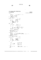
- FIG. 7 is a partial graphical representation of one set of Boolean equations for generating case numbers in accordance with this invention.
- FIGS. 8 and 9 are a graphical representations of other logic operations implementing boolean equations for generating case numbers in accordance with this invention.
- FIG. 1 depicts a low resolution color pixel image 10 as might be seen on a computer monitor such as a CRT. Elimination of jagged edges 12 and jagged lines 14 are the object of this invention.
- the system of this invention produces higher resolution virtual image 16, FIG. 2 with greatly reduced jagged edges and jagged lines as shown resulting in a more aesthetically pleasing image.
- window 30, FIG. 3A includes a set of 9 by 10 input pixels 32, 34, 36, from an input pixel map as shown.
- Input pixel 32 is white and input pixels 34 and 36 are black but they may be any of shade of grey or any other color as is known in the art.
- jagged line 38 is shown in FIG. 4.
- elemental source edge 40 between adjacent input pixels 32 and 34 of a different color is detected.
- a map of these edges is constructed and output cell 42 is generated which represents an image area including detected edge 40 and a portion of horizontally adjacent input pixels 32 and 34 as shown.
- All the edges between adjacent input pixels within the window 30 are then analyzed using a set of logic operations implementing Boolean equations in hardware. Since a much larger 9 by 10 matrix of input pixels is analyzed, a much higher accuracy is possible than in the 3 by 3 pixel matrix shown in the Xerox patent. Because the logic operations implementing the particular Boolean equations in this invention, however, there is no need for an unwieldy number of templates or "standard pixel formats".
- the Boolean equations generate a case number characterizing window 30 based on the elemental edge 40 between two adjacent input pixels of different color and the other edges between other adjacent input pixels within window 30. This case number is then used to produce an "inferred" edge segment 44, FIG. 3B within output cell (also called an inferral area) 42. This process is repeated for each output cell in the entire image.
- An eight bit "case number" representing the inferred edge segments and symmetry information are then presented as input data to the rendering system for a particular output device which outputs and colors the inferred edge segment 44 to the best of its ability depending on the resolution limit and other capabilities of the output device and the original colors in the input pixel map. See FIG. 5.
- window subsystem 60 forms a moving window within the source pixel-map.
- the window is typically an even number of pixels in the horizontal direction of the output scan and an odd number of pixels in the vertical direction.
- the window is 9 by 10 pixels with a total of 90 input pixels.
- the process of forming the moving window requires line stores if the source data is presented in raster-scan fashion, as is typical. In the case of a 9-line window, eight prior lines are stored. The ninth line is the currently inputting line and need not be stored.
- step 62 is to convert the pixel-map to edgemaps, step 60.
- An edge bit represents the boundary between two touching pixels which have different color. If they have the same color, the edge is absent or "0". If they are different, an elemental edge is present or "1". Thus two vertically adjacent pixels have an elemental horizontal edge between them, denoted as h0 to h79. Two horizontally adjacent pixels have an elemental vertical edge between them, denoted as v0 to v80. In a 9 by 10 window, there are a total of 161 elemental vertical and horizonal edges.
- the conversions of the source data into an edgemap not shown in the prior art, looses all data about the absolute color of pixels. Once the processing has made its best guess as to the intended edge, if any, in the output cell based on the edge map, then color data, bypassed around the edgemap, is added to form the final output cell.
- a corner map is used in color versions. Two pixels meeting only at their corners like red squares on a checkerboard are assigned the corner value "1" if they are different and "0" if they are the same. A checkerboard would thus have all zeros in its corner map and all ones in its horizontal and vertical edgemaps. Corner touching pixels connecting in the direction of a backslash ( ⁇ ) form a b-type corner, b0 to b79, and pixels connecting in the direction of a forward slash (/), form an f-type corner, f0 to f79. There are thus another 160 bits in the corner maps. Not all the bits are used and unused bits need not be calculated.
- edge and corner maps thus defined then pass to a series of Boolean equations, step 64 which categorize the input window as one of a number of "cases" (or “no case", called case 0).
- case 0 A representative sample of these cases is graphically shown in FIGS. 7-9.
- Each case represents a particular inferred edge segment (shown as a dashed line) within the area of the output cell 42.
- the output edges for the different cases are unique, although some are very similar and there may be incidental identities.
- the output cell, with its inferred edge is then colored based on actual source colors of adjacent input pixels. The result is the delineation of a virtual output cell of infinite resolution but usually less than perfect inferral accuracy.
- the inferred edge associated with each case number is determined as part of the inventive process of defining the equations for each case.
- infinite resolution is meant that a particular case, for instance, may call for an edge 0.1234 of the way across the cell; a few even have curved edges.
- a given output device e.g. a display or a printer, typically cannot reproduce this edge exactly, and it may be constrained to a specific pattern of sub-pixels because of its own inherent resolution capability.
- the actual infinite resolution output cell shown arbitrarily in FIGS. 7-9 is imaginary (virtual) because, while implied by the case number, it is never actually created for any given output device. Instead the case number is usually converted directly, by a lookup table, into signals to drive the output device.
- the conversion used is peculiar to a given rendering device.
- the case numbers are universal to all rendering devices, a reduced set may be used for cruder devices.
- an intermediary higher-level representation of the output cell e.g. vectors or super resolution bit map (which may be run length compressed).
- the case-recognition Boolean logic may be simplified and approximated. Thus, fewer cases may be used.
- the conversion from the case-number and symmetry to the final output drive signals is accomplished in rendering subsystem 68, FIG. 6.
- This subsystem assembles the output cells into a complete image and possibly using a separate modulator provides a drive signal 70 that the output device can accept.
- the rendering subsystem drives one or more modulators 72 or D/A converters.
- the rendering subsystem simply provides a new but enhanced pixel map of different resolution.
- the output electronic image may be in a form specific to a given output device or in a form selected to minimize hardware costs, e.g. utilizing a time-modulated signal to produce both grayscale and precision edge location by separately modulating a pulse's width and position for each elemental unit in the output image. The latter can be implemented all-digitally in the same chip as other circuitry.
- the preferred embodiment may be a hybrid where such a time-modulated signal essentially defines feature edges but is combined with D/A converter(s) to modulate the amplitude of the pulses.
- the Boolean equations which characterize each case act in parallel in hardware to permit operation in real time (dedicated hardware required for "moving" on “animated” images). All the above operations are pipelined and take roughly fifteen pipeline stages. They may also be implemented entirely or partially in software operating on a microprocessor.
- FIGS. 7-9 are sample drawings of a few representative cases. These drawings are meant to be guides to the Boolean equations which actually define the cases. They are not represented in the hardware or software implementation as templates, or any other way, and may not exactly or unambiguously equivalent to the Boolean equations. The Boolean equations also involve very substantial sharing of terms among cases (i.e. factoring), which is not shown in the drawings.
- FIG. 7 represents the area represented in the output cell for that case.
- Dashed line 100 represents the edge that is inferred when the equations for the case are satisfied. Although the inferred edge is drawn beyond the center square for clarity, only that segment of the inferred edge within the center square is used in forming the actual output cell.
- a line (e.g. 102, 104, 106, 110, 112) between two input pixels indicates that those two input pixels must be different. i.e. must have an elemental edge between them.
- a letter "X" between two input pixels indicates that those two input pixels must be the same color. i.e. have no elemental edge between them.
- a circle around a node indicates that there must be color continuity along the "clear" side of the two elemental edged meeting at the node. As discussed before, at least one side of the source edge, the so-called "clear side", must be of one continuous color while the other side may be any number of colors.
- a very complicated logical relationship among a subwindow of pixels surrounding the node is required to evaluate the circle function. That function, called the "JOIN” function, is heuristic and specified by the Boolean equations implemented by the MACRO labeled "super--join” in Appendix A.
- the subwindow for the JOIN function is six by six input pixels if those 36 pixels are available within the current main window, lesser if not.
- the purpose of the JOIN function is to guess which of two possible interpretations are to be used when all four elemental edges are present at a node.
- the guide drawings represent only one of four possible symmetries (for an odd by even window) or one of eight possible symmetries (for an even by even window).
- a near-horizontal or near vertical straight line is quantized as a jagged line with single-pixel wide jags evenly spaced.
- the correct inferred edge shown as the dashed line within the output cells shown in FIGS. 7-9, is then a slanted straight line passing though the exact center of each jag.
- This simple inferred edge is an "equal darkness" rendering. That means an area is added to the figure on one side of the jagged line which is exactly equal to the area subtracted from it.
- Enhanced text for example will then be no darker or lighter than unenhanced text.
- Each possible input pixel-map window has a left-right mirror-image and an up-down mirror image, a total of four "symmetries".
- the logic shown in Appendix A generates, in addition to case numbers, two symmetry bits. For example if case number 06, FIG. 7, occurs in vertical symmetry, it means the conditions shown in the diagram and equations for case 06 occur upside-down in the source pixel-map.
- case number 06 FIG. 7
- equations for case 06 occur upside-down in the source pixel-map.
- all 800 sets of Boolean equations are actually implemented, but three quarters of them can be generated automatically during chip design from the other one-quarter, thus saving engineering time and eliminating errors.
- the output cell sits at the corner of four input pixels and overlaps one-quarter of each. There is then a symmetry of 90° rotation in addition to the symmetries of the present design, for a total of eight-fold symmetry. This has the advantage of reducing the number of cases, for example combining near-vertical cases with near-horizontal cases, and making some near -45 cases self-symmetric.
- the net effect is a large increase in the amount of logic that is computer-generated table at the time of chip design, a large reduction in the conceptual complexity, a moderate decrease in gate count (due to new "SS" cases) in the high-speed version, and a large (roughly 50%) decrease in gate count in the time-multiplexed version using an 8 ⁇ clock.
- this will create a plethora of horizontal edges halfway between scan lines in 1:1 renderings on scanned output devices, which is very undesirable.
- This "split-line" problem is correctable by adding some complexity, namely a half-line vertical shift, to the rendering algorithm. The split-line problem does not exit in 2:1 or 4:1 renderings which would likely be used in video games and many other applications.
- edges along single-pixel-wide lines This involves detecting the other side of the line and using that information to infer the intended edge on the side being examined. These are the so-called ⁇ green ⁇ and ⁇ red ⁇ case-variations in the near-vertical and near-horizontal in FIGS. 7-14.
- Small-font lower-case t's crosses for example, often have a very small (e.g. one pixel) bump on one side of a stroke which the eye connects to a co-linear feature on the other side of the stroke.
- the correct inference would be a smoothed or rounded bump.
- the bump should be left sharp. This feature occurs in the near-vertical, near-horizontal, and splitcell cases. It works by detecting the connecting extension on the other side of one-pixel wide strokes.
- the serif exclusion also applies for certain cases. This feature recognizes that a single-pixel bump at the end of a long vertical or horizontal stroke is more likely to be an intended sharp feature (e.g. a serif) than a gentle curve to be smoothed out. Another exclusion affects rendering some distance away from the actual feature and hence many cases.
- Both near-horizontal and near-vertical cases have special tangent cases, referring to curved intended edges at the point they are exactly tangent to the vertical or the horizontal. There are also corresponding tangent cases among the near -45 cases. In every near-horizontal tangent case, the length of the straight (horizontal) unenhanced edge between jags is even, and in every near-vertical tangent case, the length of the straight (vertical) unenhanced edge between jags is odd. It is the rendering of the center, exactly tangent, output cell only that forms a "tangent" case.
- Non-central output cells including all cells in odd (vertical) or even (horizontal) respectively, tangents without a center cell are by choice not specially rendered but instead rendered the same as the corresponding non-curved (i.e. straight) intended edge. This choice is made to lower the number of cases, although a full detection of tangent cases would be more accurate.
- edgemap this is the situation when all four possible vertical and horizontal edges are present at a given inter-pixel node.
- black/white only application or in the color application where only two colors touch the node there are two possible interpretations: either a feature of one color passes through the node over a background of the other color, or vice-versa. Choosing wrong will put very visible breaks in small features in both text and cartoon art. Not choosing at all, i.e. leaving a four-corners pattern, is better than choosing wrong but leaves a significant piece of the image looking unenhanced. The choice affects rendering some distance (up to half a window) away from the node in question.
- black is always called foreground and white is always background. For normal text, this is produces the best possible result.
- Another solution is only applicable to black and white text (or two-color text). This solution detects reverse text and then treats black (or the dominant color) as background.
- a full color foreground/background detector is the most general solution. Virtually all foreground/background algorithms involve counting something, e.g. edges or pixels, and comparing numbers. Counting and comparing are simple in software and sequential hardware, but very gate-intensive in the pipelined hardware of this invention. Many things have to be counted simultaneously in a given window.
- the Boolean equations are designed to be mutually exclusive, that is if one case "hits" no other case would hit.
- Solid areas e.g. in the center of wide strokes, normally generate no case hits, that is case 0, because there are no edges to be inferred there.
- case 0 Solid areas, e.g. in the center of wide strokes, normally generate no case hits, that is case 0, because there are no edges to be inferred there.
- the existing Boolean structure will detect areas that need to be grayed when toner-saving is selected while rendering the edges fully enhanced and sharp. Further, with a precise modulator, the grayed areas can be precisely halftoned. Multiple levels of toner-saving would be readily available with few additional gates.
- lookup tables that convert from case numbers to rendering waveforms can include engine curve correction, where appropriate, with no additional gates.
- a significant minority of cases produce an inferred edge that extends left or right to a second output cell. None extend further. Special concomitant cases are used for that adjacent output cell, called shifted cases and having different case numbers.
- shifted cases Separate case diagrams are not shown from the shifted cases because their diagram is the same as the parent case except shifted one pixel right or left, hence the name.
- a left shifted case is one whose parent's diagram is shifted left and is rendered to the right of the parent case.
- the horizontal symmetry bit reverses the direction of shift. The algorithm is arranged so that shifted cases cannot occur vertically.
- Shifted cases could be implemented the same as regular cases, using Boolean equations with all the edges incremented or decremented by one count from the parent case.
- An easier way is to pipeline the final case number one additional stage and, when a parent case is detected, insert the corresponding shifted case number of the left or the right of it using either an explicit positive delay or the pipeline stage as a negative delay, respectively.
- FIGS. 7-9 are carefully organized into rows and columns on each page, even through the case numbers themselves are essentially arbitrary. Generally, with some exceptions, one half of each figure--with corresponding conditions, is the same for all cases in a given column, and the other half of each figure, with corresponding conditions, is the same for all cases in a given row. Some figure halves are the same on two different pages. This has been carefully set up this way to permit sharing of Boolean equation terms and hence a massive savings in gate count. Without this factoring, the gate count would be prohibitive.
- case 97 with its shifted case, case 29, FIG. 8 is the so-called double-jag case.
- a smooth source edge produces jags, one pixel in size, at periodic intervals in the pixel map and the spacing between jags depends on the local slope of the edge.
- a jag two pixels in size is an intended feature not to be smoothed out.
- the double-jag case along with its shifted case, correctly detects and smooths out this situation. Without it, many sharply curved edges, e.g. the inside of a small "s" are rendered improperly.
- the Boolean equations are carefully factored to increase speed when run on a "Pentium" (and higher) processors.
- the Pentium processor has two instruction-executing pipelines which operate simultaneously until one pipeline needs data from the other and then the first pipeline stalls until the data is available.
- the software computes 64 versions of each Boolean equation simultaneously, each operating on a different window across the scan line. Different equations and/or different pieces of one equation are then interleaved in the code in such a way as to minimize Pentium pipeline stall. Special macroinstructions are defined to make the assembler do most of the work in this interleaving.
- the entire code is then repeated in three versions, called "tracks", again making the assembler do the work, so that as soon as 32 of the 64 windows are resolved (i.e. all 32 hit on a case or are definite no-hits), the code switches to a faster track that only computes the remaining 32, still fully interleaved for Pentium pipelining, the Pentium being a 32 bit processor.
- the result is an entire facsimile page processed in typically less than 10 seconds.
- source DPI and destination DPI can be anything. Also, nothing in the algorithm assumes either input or output pixels are square. Hence the same hardware or software can instantly switch from 200 by 200 DPI facsimile input to 200 by 100 DPI facsimile, both current facsimile standards.
- case 99 case FIG. 8
- the rounding radius is 1.5 pixel width. This situation frequently occurs on italics. Near-horizontal and near-vertical hits that would otherwise occur in this situation are suppressed.
- an intermediate "edgemap” is formed. Its purpose is to carry only edge information through the main computation, putting aside the actual colors that butt to form the edges. After the inferred edge is computed, the colors are restored in the "renderer” prior to final output. For color images, the edge information (the “edgemap”) also requires substantially less data than the full color pixelmap, reducing the memory requirements in the line stores.
- XOR's exclusive OR's
- edges there are thus two basic kinds of elemental edges in the edgemap; horizontal edges (between vertically adjacent pixels) and vertical edges (between horizontally adjacent edges). If only two colors are possible, e.g. a black/white bitmap as source, these two types of edges are all that is needed. For operation on more than two colors, e.g. full color, the edgemap must carry two additional types of edges, really pseudo-edges, representing a comparison between pixels which touch only at a corner point, i.e. are diagonally adjacent like the black squares on a chess board.
- the four types of edges are designated “h”, “v,” “b”, and “f” for "horizontal”, “vertical”, “backslash”, and “forwardslash” respectively.
- the entire examination window into the source color pixelmap generates an edgemap of four bits per source pixel except at the edges and corners of the window.
- a ten by ten pixel window (100 total pixels) is converted to an edgemap of 351 bits.
- edgemap bits are all available simultaneously for Boolean operations and are constantly changing as the window scans across the source image.
- the optimum edge-recognition threshold varies from one source to another and can either be a manual adjustment, or automatically adjusted to maximize the extent of inferred edge recognition. Too large a threshold will result in too few elemental edges in the edgemap, "broken” edges seen by the inferrer, and just as few “hits” as the other extreme.
- How the output cell data is turned into drive signals depends on the particular display or printer device.
- One important example is displaying a lower source-resolution, e.g. 640 by 480 pixels, on a higher resolution fixed-pixel display device, e.g. a 800 by 600 pixel color LCD computer monitor.
- This type of display has tri-colored subpixels, red, green, and blue, which are arranged in triplets to make up full-color pixels.
- the display pixels can be treated as single full-color pixels.
- the preferred embodiment is to separately compute and drive each primary-color subpixel as follows, and then deliver composite full-color pixels.
- each display primary-color subpixel may partially overlap the area of 1, 2, or 4 output cells computed by the methods disclosed herein. If the source and output resolutions were exact multiples of each other (including equal), the overlap might be constrained to just one or two output cells. For the example resolutions given (and typically) one or two lines of output cells, but never more, are required to generated one horizontal line of display. Those two lines would consist of the currently computed output cell line plus one previous line stored in an OUTPUT-CELL LINE STORE. For the two resolution figures given, the output device consumes less than one source line per output line, and therefore some lines of output cells, at regular intervals, need to be repeated to create a seamless displayed image. Thereby, the 1, 2 or 4 output cells partially overlapped by a given display primary-color-subpixel, will be available as needed in real time without storing more than the one line of inferred-edge (output cell) information. No intermediary frame buffer is required.
- the value of a given display subpixel is then determined as the average green intensity within the area of that green subpixel as seen in the inferred, or output-cell, image.
- the corresponding blue subpixel will then get its value from a different, but adjacent, area in the inferred image even though the green and blue subpixels are part of the same RGB full-color pixel as conventionally driven.
- the computation of the average green intensity within the area of a particular green subpixel is determined by the appropriately weighted averages of the green intensities in the various polygons within the 1, 2, 4 output cells. If the input and output resolution are ratios of small integers to each other, or nearly so, this computation of average color values is simplified. For example, 800 and 640 (pixel-width images) are in the ratio 5:4. In this case, the primary-color subpixels overlap the 1, 2 or 4 output cells in a small number of possible patterns and lookup tables or other computational simplifications may be used.
- the Appendix A depicts, in assembly language, the actual logic operations implementing the Boolean equations which generate the case numbers as graphically depicted in FIGS. 7-9.
- the rendering subsystem logic used for demonstrating the invention is shown in Appendix B.
Abstract
Description
Claims (58)
Priority Applications (3)
| Application Number | Priority Date | Filing Date | Title |
|---|---|---|---|
| US08/685,804 US6038348A (en) | 1996-07-24 | 1996-07-24 | Pixel image enhancement system and method |
| PCT/US1997/012316 WO1998004082A2 (en) | 1996-07-24 | 1997-07-15 | Pixel image enhancement system and method |
| US09/325,137 US6526180B1 (en) | 1996-07-24 | 1999-06-03 | Pixel image enhancement system and method |
Applications Claiming Priority (1)
| Application Number | Priority Date | Filing Date | Title |
|---|---|---|---|
| US08/685,804 US6038348A (en) | 1996-07-24 | 1996-07-24 | Pixel image enhancement system and method |
Related Child Applications (1)
| Application Number | Title | Priority Date | Filing Date |
|---|---|---|---|
| US09/325,137 Continuation-In-Part US6526180B1 (en) | 1996-07-24 | 1999-06-03 | Pixel image enhancement system and method |
Publications (1)
| Publication Number | Publication Date |
|---|---|
| US6038348A true US6038348A (en) | 2000-03-14 |
Family
ID=24753735
Family Applications (2)
| Application Number | Title | Priority Date | Filing Date |
|---|---|---|---|
| US08/685,804 Expired - Lifetime US6038348A (en) | 1996-07-24 | 1996-07-24 | Pixel image enhancement system and method |
| US09/325,137 Expired - Lifetime US6526180B1 (en) | 1996-07-24 | 1999-06-03 | Pixel image enhancement system and method |
Family Applications After (1)
| Application Number | Title | Priority Date | Filing Date |
|---|---|---|---|
| US09/325,137 Expired - Lifetime US6526180B1 (en) | 1996-07-24 | 1999-06-03 | Pixel image enhancement system and method |
Country Status (2)
| Country | Link |
|---|---|
| US (2) | US6038348A (en) |
| WO (1) | WO1998004082A2 (en) |
Cited By (63)
| Publication number | Priority date | Publication date | Assignee | Title |
|---|---|---|---|---|
| US6323855B1 (en) * | 1998-12-10 | 2001-11-27 | Eastman Kodak Company | Sharpening edge features in digital image providing high frequency edge enhancement |
| US20030099411A1 (en) * | 2001-10-24 | 2003-05-29 | Nils Kokemohr | User definable image reference points |
| US20030107770A1 (en) * | 2001-07-11 | 2003-06-12 | Applied Materials, Inc. | Algorithm for adjusting edges of grayscale pixel-map images |
| US6618048B1 (en) | 1999-10-28 | 2003-09-09 | Nintendo Co., Ltd. | 3D graphics rendering system for performing Z value clamping in near-Z range to maximize scene resolution of visually important Z components |
| US20030194149A1 (en) * | 2002-04-12 | 2003-10-16 | Irwin Sobel | Imaging apparatuses, mosaic image compositing methods, video stitching methods and edgemap generation methods |
| US6636214B1 (en) | 2000-08-23 | 2003-10-21 | Nintendo Co., Ltd. | Method and apparatus for dynamically reconfiguring the order of hidden surface processing based on rendering mode |
| US20040037473A1 (en) * | 2002-08-20 | 2004-02-26 | Ahmed Mohamed N. | Systems and methods for content-based document image enhancement |
| US6700586B1 (en) | 2000-08-23 | 2004-03-02 | Nintendo Co., Ltd. | Low cost graphics with stitching processing hardware support for skeletal animation |
| US6707458B1 (en) | 2000-08-23 | 2004-03-16 | Nintendo Co., Ltd. | Method and apparatus for texture tiling in a graphics system |
| US6717577B1 (en) | 1999-10-28 | 2004-04-06 | Nintendo Co., Ltd. | Vertex cache for 3D computer graphics |
| US20040100464A1 (en) * | 2002-11-25 | 2004-05-27 | Dynamic Digital Depth Research Pty Ltd | 3D image synthesis from depth encoded source view |
| US6747642B1 (en) | 1999-01-29 | 2004-06-08 | Nintendo Co., Ltd. | Method and apparatus for providing non-photorealistic cartoon outlining within a 3D videographics system |
| US6811489B1 (en) | 2000-08-23 | 2004-11-02 | Nintendo Co., Ltd. | Controller interface for a graphics system |
| US20050036175A1 (en) * | 2001-07-11 | 2005-02-17 | Asher Klatchko | Optical proximity correction in raster scan printing based on grayscale manipulation of the bitmap |
| US20050162436A1 (en) * | 2000-08-23 | 2005-07-28 | Nintendo Co., Ltd. | Graphics system with embedded frame buffer having reconfigurable pixel formats |
| US20050195210A1 (en) * | 2000-08-23 | 2005-09-08 | Nintendo Co., Ltd. | Method and apparatus for efficient generation of texture coordinate displacements for implementing emboss-style bump mapping in a graphics rendering system |
| US20050251761A1 (en) * | 2003-09-15 | 2005-11-10 | Diamond Michael B | Integrated circuit configuration system and method |
| US20050278666A1 (en) * | 2003-09-15 | 2005-12-15 | Diamond Michael B | System and method for testing and configuring semiconductor functional circuits |
| US20060001688A1 (en) * | 2004-07-01 | 2006-01-05 | Chabreck Thomas E | Area based optical proximity correction in raster scan printing |
| US20060139353A1 (en) * | 2004-12-24 | 2006-06-29 | Konica Minolta Business Technologies, Inc. | Image processing apparatus |
| US20060256384A1 (en) * | 1997-06-09 | 2006-11-16 | Seiko Epson Corporation | Image processing apparatus, an image processing method, a medium on which an image processing control program is recorded, an image evaluation device, an image evaluation method and a medium on which an image evaluation program is recorded |
| EP1734737A1 (en) * | 2005-06-17 | 2006-12-20 | Konica Minolta Business Technologies, Inc. | Image processing method and a recording medium storing image processing program |
| US20070160285A1 (en) * | 2002-05-01 | 2007-07-12 | Jay Stephen Gondek | Method and apparatus for associating image enhancement with color |
| US20070165043A1 (en) * | 2000-08-23 | 2007-07-19 | Nintendo Co., Ltd. | Method and apparatus for buffering graphics data in a graphics system |
| US20080106328A1 (en) * | 2004-09-15 | 2008-05-08 | Diamond Michael B | Semiconductor die micro electro-mechanical switch management system and method |
| US20090103443A1 (en) * | 2007-10-22 | 2009-04-23 | Ting Sheng Ku | Loopback configuration for bi-directional interfaces |
| US7529421B2 (en) | 2004-07-01 | 2009-05-05 | Applied Materials, Inc. | Optical proximity correction in raster scan printing based on corner matching templates |
| US20090153912A1 (en) * | 2007-12-18 | 2009-06-18 | Mohamed Nooman Ahmed | Scanner Calibration Strip, Scanner, and Method for Segmenting a Scanned Document Image |
| US20090225094A1 (en) * | 2000-08-23 | 2009-09-10 | Nintendo Co., Ltd. | Graphics Processing System with Enhanced Memory Controller |
| US20090259965A1 (en) * | 2008-04-10 | 2009-10-15 | Davidson Philip L | Methods of interfacing with multi-input devices and multi-input display systems employing interfacing techniques |
| US20090324090A1 (en) * | 2008-06-30 | 2009-12-31 | Kabushiki Kaisha Toshiba | Information processing apparatus and image processing method |
| US20100039448A1 (en) * | 2001-10-24 | 2010-02-18 | Nik Software, Inc. | Distortion of Digital Images Using Spatial Offsets |
| US20100073394A1 (en) * | 2000-08-23 | 2010-03-25 | Nintendo Co., Ltd. | Graphics system with embedded frame buffer having reconfigurable pixel formats |
| US20100135593A1 (en) * | 2008-11-28 | 2010-06-03 | Kabushiki Kaisha Toshiba | Information processing apparatus and resolution enhancement processing control program |
| US8482567B1 (en) * | 2006-11-03 | 2013-07-09 | Nvidia Corporation | Line rasterization techniques |
| WO2013109478A1 (en) * | 2012-01-12 | 2013-07-25 | Kofax, Inc. | Systems and methods for mobile image capture and processing |
| US20130236122A1 (en) * | 2010-09-30 | 2013-09-12 | St-Ericsson Sa | Method and Device for Forming a Panoramic Image |
| US8711161B1 (en) | 2003-12-18 | 2014-04-29 | Nvidia Corporation | Functional component compensation reconfiguration system and method |
| US8711156B1 (en) | 2004-09-30 | 2014-04-29 | Nvidia Corporation | Method and system for remapping processing elements in a pipeline of a graphics processing unit |
| US8732644B1 (en) | 2003-09-15 | 2014-05-20 | Nvidia Corporation | Micro electro mechanical switch system and method for testing and configuring semiconductor functional circuits |
| US8885229B1 (en) | 2013-05-03 | 2014-11-11 | Kofax, Inc. | Systems and methods for detecting and classifying objects in video captured using mobile devices |
| US8958605B2 (en) | 2009-02-10 | 2015-02-17 | Kofax, Inc. | Systems, methods and computer program products for determining document validity |
| US9058580B1 (en) | 2012-01-12 | 2015-06-16 | Kofax, Inc. | Systems and methods for identification document processing and business workflow integration |
| US9058515B1 (en) | 2012-01-12 | 2015-06-16 | Kofax, Inc. | Systems and methods for identification document processing and business workflow integration |
| US9137417B2 (en) | 2005-03-24 | 2015-09-15 | Kofax, Inc. | Systems and methods for processing video data |
| US9141926B2 (en) | 2013-04-23 | 2015-09-22 | Kofax, Inc. | Smart mobile application development platform |
| US9208536B2 (en) | 2013-09-27 | 2015-12-08 | Kofax, Inc. | Systems and methods for three dimensional geometric reconstruction of captured image data |
| US9311531B2 (en) | 2013-03-13 | 2016-04-12 | Kofax, Inc. | Systems and methods for classifying objects in digital images captured using mobile devices |
| US9331869B2 (en) | 2010-03-04 | 2016-05-03 | Nvidia Corporation | Input/output request packet handling techniques by a device specific kernel mode driver |
| US9355312B2 (en) | 2013-03-13 | 2016-05-31 | Kofax, Inc. | Systems and methods for classifying objects in digital images captured using mobile devices |
| US9386235B2 (en) | 2013-11-15 | 2016-07-05 | Kofax, Inc. | Systems and methods for generating composite images of long documents using mobile video data |
| US9396388B2 (en) | 2009-02-10 | 2016-07-19 | Kofax, Inc. | Systems, methods and computer program products for determining document validity |
| US9483794B2 (en) | 2012-01-12 | 2016-11-01 | Kofax, Inc. | Systems and methods for identification document processing and business workflow integration |
| US9576272B2 (en) | 2009-02-10 | 2017-02-21 | Kofax, Inc. | Systems, methods and computer program products for determining document validity |
| US9665928B1 (en) * | 2015-12-14 | 2017-05-30 | Ambit Microsystems (Shanghai) Ltd. | Color image processing system and color image processing method |
| US9747269B2 (en) | 2009-02-10 | 2017-08-29 | Kofax, Inc. | Smart optical input/output (I/O) extension for context-dependent workflows |
| US9760788B2 (en) | 2014-10-30 | 2017-09-12 | Kofax, Inc. | Mobile document detection and orientation based on reference object characteristics |
| US9769354B2 (en) | 2005-03-24 | 2017-09-19 | Kofax, Inc. | Systems and methods of processing scanned data |
| US9767354B2 (en) | 2009-02-10 | 2017-09-19 | Kofax, Inc. | Global geographic information retrieval, validation, and normalization |
| US9779296B1 (en) | 2016-04-01 | 2017-10-03 | Kofax, Inc. | Content-based detection and three dimensional geometric reconstruction of objects in image and video data |
| US10146795B2 (en) | 2012-01-12 | 2018-12-04 | Kofax, Inc. | Systems and methods for mobile image capture and processing |
| US10242285B2 (en) | 2015-07-20 | 2019-03-26 | Kofax, Inc. | Iterative recognition-guided thresholding and data extraction |
| US10803350B2 (en) | 2017-11-30 | 2020-10-13 | Kofax, Inc. | Object detection and image cropping using a multi-detector approach |
Families Citing this family (6)
| Publication number | Priority date | Publication date | Assignee | Title |
|---|---|---|---|---|
| US7417640B1 (en) * | 1999-01-29 | 2008-08-26 | Lg Electronics Inc. | Method for dominant color setting of video region and data structure and method of confidence measure extraction |
| US7088351B2 (en) * | 2003-03-09 | 2006-08-08 | Lsi Logic Corporation | Real time image enhancement with adaptive noise reduction and edge detection |
| US20050017969A1 (en) * | 2003-05-27 | 2005-01-27 | Pradeep Sen | Computer graphics rendering using boundary information |
| KR100611981B1 (en) * | 2004-05-01 | 2006-08-11 | 삼성전자주식회사 | Method and apparatus for halftoning digital images |
| US7679620B2 (en) * | 2005-07-28 | 2010-03-16 | Microsoft Corp. | Image processing using saltating samples |
| JP5406703B2 (en) * | 2009-12-25 | 2014-02-05 | キヤノン株式会社 | Image processing apparatus, image processing method, and image forming apparatus |
Citations (3)
| Publication number | Priority date | Publication date | Assignee | Title |
|---|---|---|---|---|
| US4437122A (en) * | 1981-09-12 | 1984-03-13 | Xerox Corporation | Low resolution raster images |
| US4847641A (en) * | 1988-08-16 | 1989-07-11 | Hewlett-Packard Company | Piece-wise print image enhancement for dot matrix printers |
| US5481627A (en) * | 1993-08-31 | 1996-01-02 | Daewoo Electronics Co., Ltd. | Method for rectifying channel errors in a transmitted image signal encoded by classified vector quantization |
Family Cites Families (1)
| Publication number | Priority date | Publication date | Assignee | Title |
|---|---|---|---|---|
| US5404233A (en) * | 1990-08-28 | 1995-04-04 | Kyocera Corporation | Method for smoothing image |
-
1996
- 1996-07-24 US US08/685,804 patent/US6038348A/en not_active Expired - Lifetime
-
1997
- 1997-07-15 WO PCT/US1997/012316 patent/WO1998004082A2/en active Application Filing
-
1999
- 1999-06-03 US US09/325,137 patent/US6526180B1/en not_active Expired - Lifetime
Patent Citations (4)
| Publication number | Priority date | Publication date | Assignee | Title |
|---|---|---|---|---|
| US4437122A (en) * | 1981-09-12 | 1984-03-13 | Xerox Corporation | Low resolution raster images |
| US4437122B1 (en) * | 1981-09-12 | 1993-03-30 | Xerox Corp | |
| US4847641A (en) * | 1988-08-16 | 1989-07-11 | Hewlett-Packard Company | Piece-wise print image enhancement for dot matrix printers |
| US5481627A (en) * | 1993-08-31 | 1996-01-02 | Daewoo Electronics Co., Ltd. | Method for rectifying channel errors in a transmitted image signal encoded by classified vector quantization |
Cited By (126)
| Publication number | Priority date | Publication date | Assignee | Title |
|---|---|---|---|---|
| US20060256384A1 (en) * | 1997-06-09 | 2006-11-16 | Seiko Epson Corporation | Image processing apparatus, an image processing method, a medium on which an image processing control program is recorded, an image evaluation device, an image evaluation method and a medium on which an image evaluation program is recorded |
| US7940426B2 (en) * | 1997-06-09 | 2011-05-10 | Seiko Epson Corporation | Image processing apparatus, an image processing method, a medium on which an image processing control program is recorded, an image evaluation device, an image evaluation method and a medium on which an image evaluation program is recorded |
| US8867099B2 (en) | 1997-06-09 | 2014-10-21 | Seiko Epson Corporation | Image processing apparatus, an image processing method, a medium on which an image processing control program is recorded, an image evaluation device, an image evaluation method and a medium on which an image evaluation program is recorded |
| US8553285B2 (en) | 1997-06-09 | 2013-10-08 | Seiko Epson Corporation | Image processing apparatus, an image processing method, a medium on which an image processing control program is recorded, an image evaluation device, an image evaluation method and a medium on which an image evaluation program is recorded |
| US20110188776A1 (en) * | 1997-06-09 | 2011-08-04 | Seiko Epson Corporation | Image processing method and image processing apparatus |
| US8681380B2 (en) | 1997-06-09 | 2014-03-25 | Seiko Epson Corporation | Image processing apparatus, an image processing method, a medium on which an image processing control program is recorded, an image evaluation device, an image evaluation method and a medium on which an image evaluation program is recorded |
| US6323855B1 (en) * | 1998-12-10 | 2001-11-27 | Eastman Kodak Company | Sharpening edge features in digital image providing high frequency edge enhancement |
| US6747642B1 (en) | 1999-01-29 | 2004-06-08 | Nintendo Co., Ltd. | Method and apparatus for providing non-photorealistic cartoon outlining within a 3D videographics system |
| US6618048B1 (en) | 1999-10-28 | 2003-09-09 | Nintendo Co., Ltd. | 3D graphics rendering system for performing Z value clamping in near-Z range to maximize scene resolution of visually important Z components |
| US6717577B1 (en) | 1999-10-28 | 2004-04-06 | Nintendo Co., Ltd. | Vertex cache for 3D computer graphics |
| US20050162436A1 (en) * | 2000-08-23 | 2005-07-28 | Nintendo Co., Ltd. | Graphics system with embedded frame buffer having reconfigurable pixel formats |
| US20100073394A1 (en) * | 2000-08-23 | 2010-03-25 | Nintendo Co., Ltd. | Graphics system with embedded frame buffer having reconfigurable pixel formats |
| US6700586B1 (en) | 2000-08-23 | 2004-03-02 | Nintendo Co., Ltd. | Low cost graphics with stitching processing hardware support for skeletal animation |
| US6811489B1 (en) | 2000-08-23 | 2004-11-02 | Nintendo Co., Ltd. | Controller interface for a graphics system |
| US8098255B2 (en) | 2000-08-23 | 2012-01-17 | Nintendo Co., Ltd. | Graphics processing system with enhanced memory controller |
| US20090225094A1 (en) * | 2000-08-23 | 2009-09-10 | Nintendo Co., Ltd. | Graphics Processing System with Enhanced Memory Controller |
| US6707458B1 (en) | 2000-08-23 | 2004-03-16 | Nintendo Co., Ltd. | Method and apparatus for texture tiling in a graphics system |
| US20050195210A1 (en) * | 2000-08-23 | 2005-09-08 | Nintendo Co., Ltd. | Method and apparatus for efficient generation of texture coordinate displacements for implementing emboss-style bump mapping in a graphics rendering system |
| US6636214B1 (en) | 2000-08-23 | 2003-10-21 | Nintendo Co., Ltd. | Method and apparatus for dynamically reconfiguring the order of hidden surface processing based on rendering mode |
| US20070165043A1 (en) * | 2000-08-23 | 2007-07-19 | Nintendo Co., Ltd. | Method and apparatus for buffering graphics data in a graphics system |
| US7995069B2 (en) | 2000-08-23 | 2011-08-09 | Nintendo Co., Ltd. | Graphics system with embedded frame buffer having reconfigurable pixel formats |
| US7701461B2 (en) | 2000-08-23 | 2010-04-20 | Nintendo Co., Ltd. | Method and apparatus for buffering graphics data in a graphics system |
| US20030107770A1 (en) * | 2001-07-11 | 2003-06-12 | Applied Materials, Inc. | Algorithm for adjusting edges of grayscale pixel-map images |
| US7034963B2 (en) | 2001-07-11 | 2006-04-25 | Applied Materials, Inc. | Method for adjusting edges of grayscale pixel-map images |
| US7420710B2 (en) | 2001-07-11 | 2008-09-02 | Applied Materials, Inc. | Optical proximity correction in raster scan printing based on grayscale manipulation of the bitmap |
| US20050036175A1 (en) * | 2001-07-11 | 2005-02-17 | Asher Klatchko | Optical proximity correction in raster scan printing based on grayscale manipulation of the bitmap |
| US6728421B2 (en) | 2001-10-24 | 2004-04-27 | Nik Multimedia, Inc. | User definable image reference points |
| US6865300B2 (en) | 2001-10-24 | 2005-03-08 | Nik Multimedia, Inc. | User definable image reference points |
| US9471998B2 (en) | 2001-10-24 | 2016-10-18 | Google Inc. | Distortion of digital images using spatial offsets from image reference points |
| US9008420B2 (en) | 2001-10-24 | 2015-04-14 | Google Inc. | Distortion of digital images using spatial offsets from image reference points |
| US20030099411A1 (en) * | 2001-10-24 | 2003-05-29 | Nils Kokemohr | User definable image reference points |
| US9786031B2 (en) | 2001-10-24 | 2017-10-10 | Google Inc. | Distortion of digital images using spatial offsets from image reference points |
| US20100039448A1 (en) * | 2001-10-24 | 2010-02-18 | Nik Software, Inc. | Distortion of Digital Images Using Spatial Offsets |
| US10140682B2 (en) | 2001-10-24 | 2018-11-27 | Google Llc | Distortion of digital images using spatial offsets from image reference points |
| US7970233B2 (en) | 2001-10-24 | 2011-06-28 | Nik Software, Inc. | Distortion of digital images using spatial offsets from image reference points |
| US20100303379A1 (en) * | 2001-10-24 | 2010-12-02 | Nik Software, Inc. | Distortion of digital images using spatial offsets from image reference points |
| US8625925B2 (en) | 2001-10-24 | 2014-01-07 | Google Inc. | Distortion of digital images using spatial offsets from image reference points |
| US20100027908A1 (en) * | 2001-10-24 | 2010-02-04 | Nik Software, Inc. | Distortion of Digital Images Using Spatial Offsets From Image Reference Points |
| US8064725B2 (en) | 2001-10-24 | 2011-11-22 | Nik Software, Inc. | Distortion of digital images using spatial offsets |
| US20030194149A1 (en) * | 2002-04-12 | 2003-10-16 | Irwin Sobel | Imaging apparatuses, mosaic image compositing methods, video stitching methods and edgemap generation methods |
| US7006706B2 (en) | 2002-04-12 | 2006-02-28 | Hewlett-Packard Development Company, L.P. | Imaging apparatuses, mosaic image compositing methods, video stitching methods and edgemap generation methods |
| US20070160285A1 (en) * | 2002-05-01 | 2007-07-12 | Jay Stephen Gondek | Method and apparatus for associating image enhancement with color |
| US7079686B2 (en) | 2002-08-20 | 2006-07-18 | Lexmark International, Inc. | Systems and methods for content-based document image enhancement |
| US20040037473A1 (en) * | 2002-08-20 | 2004-02-26 | Ahmed Mohamed N. | Systems and methods for content-based document image enhancement |
| US7126598B2 (en) * | 2002-11-25 | 2006-10-24 | Dynamic Digital Depth Research Pty Ltd. | 3D image synthesis from depth encoded source view |
| US20040100464A1 (en) * | 2002-11-25 | 2004-05-27 | Dynamic Digital Depth Research Pty Ltd | 3D image synthesis from depth encoded source view |
| US8732644B1 (en) | 2003-09-15 | 2014-05-20 | Nvidia Corporation | Micro electro mechanical switch system and method for testing and configuring semiconductor functional circuits |
| US8768642B2 (en) | 2003-09-15 | 2014-07-01 | Nvidia Corporation | System and method for remotely configuring semiconductor functional circuits |
| US8775997B2 (en) | 2003-09-15 | 2014-07-08 | Nvidia Corporation | System and method for testing and configuring semiconductor functional circuits |
| US8775112B2 (en) | 2003-09-15 | 2014-07-08 | Nvidia Corporation | System and method for increasing die yield |
| US8788996B2 (en) | 2003-09-15 | 2014-07-22 | Nvidia Corporation | System and method for configuring semiconductor functional circuits |
| US8872833B2 (en) | 2003-09-15 | 2014-10-28 | Nvidia Corporation | Integrated circuit configuration system and method |
| US20050278666A1 (en) * | 2003-09-15 | 2005-12-15 | Diamond Michael B | System and method for testing and configuring semiconductor functional circuits |
| US20050261863A1 (en) * | 2003-09-15 | 2005-11-24 | Van Dyke James M | Integrated circuit configuration system and method |
| US20050251761A1 (en) * | 2003-09-15 | 2005-11-10 | Diamond Michael B | Integrated circuit configuration system and method |
| US8711161B1 (en) | 2003-12-18 | 2014-04-29 | Nvidia Corporation | Functional component compensation reconfiguration system and method |
| US7529421B2 (en) | 2004-07-01 | 2009-05-05 | Applied Materials, Inc. | Optical proximity correction in raster scan printing based on corner matching templates |
| US7407252B2 (en) | 2004-07-01 | 2008-08-05 | Applied Materials, Inc. | Area based optical proximity correction in raster scan printing |
| US20060001688A1 (en) * | 2004-07-01 | 2006-01-05 | Chabreck Thomas E | Area based optical proximity correction in raster scan printing |
| US20080106328A1 (en) * | 2004-09-15 | 2008-05-08 | Diamond Michael B | Semiconductor die micro electro-mechanical switch management system and method |
| US8704275B2 (en) | 2004-09-15 | 2014-04-22 | Nvidia Corporation | Semiconductor die micro electro-mechanical switch management method |
| US8723231B1 (en) | 2004-09-15 | 2014-05-13 | Nvidia Corporation | Semiconductor die micro electro-mechanical switch management system and method |
| US8711156B1 (en) | 2004-09-30 | 2014-04-29 | Nvidia Corporation | Method and system for remapping processing elements in a pipeline of a graphics processing unit |
| US20060139353A1 (en) * | 2004-12-24 | 2006-06-29 | Konica Minolta Business Technologies, Inc. | Image processing apparatus |
| US7619627B2 (en) * | 2004-12-24 | 2009-11-17 | Konica Minolta Business Technologies, Inc. | Image processing apparatus |
| US9137417B2 (en) | 2005-03-24 | 2015-09-15 | Kofax, Inc. | Systems and methods for processing video data |
| US9769354B2 (en) | 2005-03-24 | 2017-09-19 | Kofax, Inc. | Systems and methods of processing scanned data |
| EP1734737A1 (en) * | 2005-06-17 | 2006-12-20 | Konica Minolta Business Technologies, Inc. | Image processing method and a recording medium storing image processing program |
| US20060285167A1 (en) * | 2005-06-17 | 2006-12-21 | Konica Minolta Business Technologies, Inc. | Image processing method and a recording medium storing image processing program |
| US8482567B1 (en) * | 2006-11-03 | 2013-07-09 | Nvidia Corporation | Line rasterization techniques |
| US8724483B2 (en) | 2007-10-22 | 2014-05-13 | Nvidia Corporation | Loopback configuration for bi-directional interfaces |
| US20090103443A1 (en) * | 2007-10-22 | 2009-04-23 | Ting Sheng Ku | Loopback configuration for bi-directional interfaces |
| US20090153912A1 (en) * | 2007-12-18 | 2009-06-18 | Mohamed Nooman Ahmed | Scanner Calibration Strip, Scanner, and Method for Segmenting a Scanned Document Image |
| US20090259965A1 (en) * | 2008-04-10 | 2009-10-15 | Davidson Philip L | Methods of interfacing with multi-input devices and multi-input display systems employing interfacing techniques |
| US9372591B2 (en) | 2008-04-10 | 2016-06-21 | Perceptive Pixel, Inc. | Methods of interfacing with multi-input devices and multi-input display systems employing interfacing techniques |
| US9256342B2 (en) * | 2008-04-10 | 2016-02-09 | Perceptive Pixel, Inc. | Methods of interfacing with multi-input devices and multi-input display systems employing interfacing techniques |
| US7945120B2 (en) * | 2008-06-30 | 2011-05-17 | Kabushiki Kaisha Toshiba | Apparatus for enhancing resolution using edge detection |
| US20090324090A1 (en) * | 2008-06-30 | 2009-12-31 | Kabushiki Kaisha Toshiba | Information processing apparatus and image processing method |
| US7941005B2 (en) | 2008-11-28 | 2011-05-10 | Kabushiki Kaisha Toshiba | Information processing apparatus and resolution enhancement processing control program |
| US20100135593A1 (en) * | 2008-11-28 | 2010-06-03 | Kabushiki Kaisha Toshiba | Information processing apparatus and resolution enhancement processing control program |
| US9396388B2 (en) | 2009-02-10 | 2016-07-19 | Kofax, Inc. | Systems, methods and computer program products for determining document validity |
| US8958605B2 (en) | 2009-02-10 | 2015-02-17 | Kofax, Inc. | Systems, methods and computer program products for determining document validity |
| US9747269B2 (en) | 2009-02-10 | 2017-08-29 | Kofax, Inc. | Smart optical input/output (I/O) extension for context-dependent workflows |
| US9576272B2 (en) | 2009-02-10 | 2017-02-21 | Kofax, Inc. | Systems, methods and computer program products for determining document validity |
| US9767354B2 (en) | 2009-02-10 | 2017-09-19 | Kofax, Inc. | Global geographic information retrieval, validation, and normalization |
| US9331869B2 (en) | 2010-03-04 | 2016-05-03 | Nvidia Corporation | Input/output request packet handling techniques by a device specific kernel mode driver |
| US20130236122A1 (en) * | 2010-09-30 | 2013-09-12 | St-Ericsson Sa | Method and Device for Forming a Panoramic Image |
| US9042676B2 (en) * | 2010-09-30 | 2015-05-26 | St-Ericsson Sa | Method and device for forming a panoramic image |
| US9342742B2 (en) | 2012-01-12 | 2016-05-17 | Kofax, Inc. | Systems and methods for mobile image capture and processing |
| US8989515B2 (en) | 2012-01-12 | 2015-03-24 | Kofax, Inc. | Systems and methods for mobile image capture and processing |
| US10657600B2 (en) | 2012-01-12 | 2020-05-19 | Kofax, Inc. | Systems and methods for mobile image capture and processing |
| US8971587B2 (en) | 2012-01-12 | 2015-03-03 | Kofax, Inc. | Systems and methods for mobile image capture and processing |
| US9165187B2 (en) | 2012-01-12 | 2015-10-20 | Kofax, Inc. | Systems and methods for mobile image capture and processing |
| WO2013109478A1 (en) * | 2012-01-12 | 2013-07-25 | Kofax, Inc. | Systems and methods for mobile image capture and processing |
| US9158967B2 (en) | 2012-01-12 | 2015-10-13 | Kofax, Inc. | Systems and methods for mobile image capture and processing |
| US9058580B1 (en) | 2012-01-12 | 2015-06-16 | Kofax, Inc. | Systems and methods for identification document processing and business workflow integration |
| US9058515B1 (en) | 2012-01-12 | 2015-06-16 | Kofax, Inc. | Systems and methods for identification document processing and business workflow integration |
| US10664919B2 (en) | 2012-01-12 | 2020-05-26 | Kofax, Inc. | Systems and methods for mobile image capture and processing |
| US10146795B2 (en) | 2012-01-12 | 2018-12-04 | Kofax, Inc. | Systems and methods for mobile image capture and processing |
| US9165188B2 (en) | 2012-01-12 | 2015-10-20 | Kofax, Inc. | Systems and methods for mobile image capture and processing |
| US8879120B2 (en) | 2012-01-12 | 2014-11-04 | Kofax, Inc. | Systems and methods for mobile image capture and processing |
| US9483794B2 (en) | 2012-01-12 | 2016-11-01 | Kofax, Inc. | Systems and methods for identification document processing and business workflow integration |
| US9514357B2 (en) | 2012-01-12 | 2016-12-06 | Kofax, Inc. | Systems and methods for mobile image capture and processing |
| US9117117B2 (en) | 2012-01-12 | 2015-08-25 | Kofax, Inc. | Systems and methods for mobile image capture and processing |
| US8855375B2 (en) | 2012-01-12 | 2014-10-07 | Kofax, Inc. | Systems and methods for mobile image capture and processing |
| US10127441B2 (en) | 2013-03-13 | 2018-11-13 | Kofax, Inc. | Systems and methods for classifying objects in digital images captured using mobile devices |
| US9996741B2 (en) | 2013-03-13 | 2018-06-12 | Kofax, Inc. | Systems and methods for classifying objects in digital images captured using mobile devices |
| US9355312B2 (en) | 2013-03-13 | 2016-05-31 | Kofax, Inc. | Systems and methods for classifying objects in digital images captured using mobile devices |
| US9754164B2 (en) | 2013-03-13 | 2017-09-05 | Kofax, Inc. | Systems and methods for classifying objects in digital images captured using mobile devices |
| US9311531B2 (en) | 2013-03-13 | 2016-04-12 | Kofax, Inc. | Systems and methods for classifying objects in digital images captured using mobile devices |
| US10146803B2 (en) | 2013-04-23 | 2018-12-04 | Kofax, Inc | Smart mobile application development platform |
| US9141926B2 (en) | 2013-04-23 | 2015-09-22 | Kofax, Inc. | Smart mobile application development platform |
| US9253349B2 (en) | 2013-05-03 | 2016-02-02 | Kofax, Inc. | Systems and methods for detecting and classifying objects in video captured using mobile devices |
| US9584729B2 (en) | 2013-05-03 | 2017-02-28 | Kofax, Inc. | Systems and methods for improving video captured using mobile devices |
| US8885229B1 (en) | 2013-05-03 | 2014-11-11 | Kofax, Inc. | Systems and methods for detecting and classifying objects in video captured using mobile devices |
| US9208536B2 (en) | 2013-09-27 | 2015-12-08 | Kofax, Inc. | Systems and methods for three dimensional geometric reconstruction of captured image data |
| US9946954B2 (en) | 2013-09-27 | 2018-04-17 | Kofax, Inc. | Determining distance between an object and a capture device based on captured image data |
| US9747504B2 (en) | 2013-11-15 | 2017-08-29 | Kofax, Inc. | Systems and methods for generating composite images of long documents using mobile video data |
| US9386235B2 (en) | 2013-11-15 | 2016-07-05 | Kofax, Inc. | Systems and methods for generating composite images of long documents using mobile video data |
| US9760788B2 (en) | 2014-10-30 | 2017-09-12 | Kofax, Inc. | Mobile document detection and orientation based on reference object characteristics |
| US10242285B2 (en) | 2015-07-20 | 2019-03-26 | Kofax, Inc. | Iterative recognition-guided thresholding and data extraction |
| US20170169547A1 (en) * | 2015-12-14 | 2017-06-15 | Ambit Microsystems (Shanghai) Ltd. | Color image processing system and color image processing method |
| US9665928B1 (en) * | 2015-12-14 | 2017-05-30 | Ambit Microsystems (Shanghai) Ltd. | Color image processing system and color image processing method |
| US9779296B1 (en) | 2016-04-01 | 2017-10-03 | Kofax, Inc. | Content-based detection and three dimensional geometric reconstruction of objects in image and video data |
| US10803350B2 (en) | 2017-11-30 | 2020-10-13 | Kofax, Inc. | Object detection and image cropping using a multi-detector approach |
| US11062176B2 (en) | 2017-11-30 | 2021-07-13 | Kofax, Inc. | Object detection and image cropping using a multi-detector approach |
Also Published As
| Publication number | Publication date |
|---|---|
| WO1998004082A2 (en) | 1998-01-29 |
| WO1998004082A3 (en) | 1998-04-09 |
| US6526180B1 (en) | 2003-02-25 |
Similar Documents
| Publication | Publication Date | Title |
|---|---|---|
| US6038348A (en) | Pixel image enhancement system and method | |
| US7945114B2 (en) | Image transform method for obtaining expanded image data, image processing apparatus and image display device therefore | |
| US5754710A (en) | Image resolution conversion method and appratus thereof | |
| US5282057A (en) | Bit-map image resolution converter | |
| US4290084A (en) | Method and means for preserving original continuity/discontinuity among same colored pel clusters upon array compression | |
| US7116443B2 (en) | Neutral pixel detection using color space feature vectors wherein one color space coordinate represents lightness | |
| US6272261B1 (en) | Image processing device | |
| US4454506A (en) | Method and circuitry for reducing flicker in symbol displays | |
| JP2967014B2 (en) | Image processing device | |
| US4992955A (en) | Apparatus for representing continuous tone and high contrast images on a bilevel display | |
| EP0613290B1 (en) | Method and apparatus for binary image data compression | |
| US5583953A (en) | Intelligent doubling for low-cost image buffers | |
| EP1734737B1 (en) | Image processing method and a recording medium storing image processing program | |
| US6501565B1 (en) | Method and apparatus for smoothing text outlines | |
| US6034700A (en) | Efficient run-based anti-aliasing | |
| US6091859A (en) | Image data enlarging/smoothing processor | |
| JP2543267B2 (en) | Image reduction device and image display device | |
| US7756353B2 (en) | Edge enhancement method for halftone image | |
| EP0616463B1 (en) | Apparatus for smoothed scaling of facsimile images | |
| EP0559393B1 (en) | Method for phase aligned NTH bitting of graphics applications | |
| JPH05268465A (en) | Method and device for post-processing image data context-sensitively | |
| JP3191409B2 (en) | Font data generator | |
| JP2878695B2 (en) | Image processing apparatus and multi-value image estimation method | |
| US7079699B2 (en) | Multi-valued image conversion device, multi-valued image conversion program, and multi-valued image conversion method | |
| JP3392800B2 (en) | Interpolation method and apparatus, and recording medium |
Legal Events
| Date | Code | Title | Description |
|---|---|---|---|
| AS | Assignment |
Owner name: XLI CORPORATION, MASSACHUSETTS Free format text: ASSIGNMENT OF ASSIGNORS INTEREST;ASSIGNOR:CARLEY, ADAM;REEL/FRAME:008189/0663 Effective date: 19960723 |
|
| AS | Assignment |
Owner name: CARLEY CORPORATION, NEW HAMPSHIRE Free format text: JOINT OWNERSHIP AGREEMENT;ASSIGNOR:XEROGRAPHIC LASER IMAGES CORPORATION;REEL/FRAME:008872/0374 Effective date: 19970212 |
|
| AS | Assignment |
Owner name: OAK TECHNOLOGY, INC., CALIFORNIA Free format text: ASSIGNMENT OF ASSIGNORS INTEREST;ASSIGNOR:XEROGRAPHIC LASER IMAGES CORPORATION;REEL/FRAME:009516/0248 Effective date: 19981005 |
|
| AS | Assignment |
Owner name: OAK TECHNOLOGY, INC., CALIFORNIA Free format text: ASSIGNMENT OF ASSIGNORS INTEREST;ASSIGNORS:XEROGRAPHIC LASER IMAGES CORPORATION;CARLEY CORPORATION;REEL/FRAME:009570/0107 Effective date: 19981106 |
|
| FEPP | Fee payment procedure |
Free format text: ENTITY STATUS SET TO UNDISCOUNTED (ORIGINAL EVENT CODE: BIG.); ENTITY STATUS OF PATENT OWNER: LARGE ENTITY |
|
| STCF | Information on status: patent grant |
Free format text: PATENTED CASE |
|
| FEPP | Fee payment procedure |
Free format text: PAYOR NUMBER ASSIGNED (ORIGINAL EVENT CODE: ASPN); ENTITY STATUS OF PATENT OWNER: LARGE ENTITY |
|
| FPAY | Fee payment |
Year of fee payment: 4 |
|
| AS | Assignment |
Owner name: ZORAN CORPORATION, CALIFORNIA Free format text: MERGER;ASSIGNOR:OAK TEDCHNOLOGY, INC.;REEL/FRAME:016038/0856 Effective date: 20030811 |
|
| FPAY | Fee payment |
Year of fee payment: 8 |
|
| FPAY | Fee payment |
Year of fee payment: 12 |
|
| AS | Assignment |
Owner name: CSR TECHNOLOGY INC., CALIFORNIA Free format text: ASSIGNMENT OF ASSIGNORS INTEREST;ASSIGNOR:ZORAN CORPORATION;REEL/FRAME:027550/0695 Effective date: 20120101 |
|
| AS | Assignment |
Owner name: CSR TECHNOLOGY INC., CALIFORNIA Free format text: ASSIGNMENT OF ASSIGNORS INTEREST;ASSIGNOR:ZORAN CORPORATION;REEL/FRAME:036642/0395 Effective date: 20150915 |
|
| FEPP | Fee payment procedure |
Free format text: PAYER NUMBER DE-ASSIGNED (ORIGINAL EVENT CODE: RMPN); ENTITY STATUS OF PATENT OWNER: LARGE ENTITY Free format text: PAYOR NUMBER ASSIGNED (ORIGINAL EVENT CODE: ASPN); ENTITY STATUS OF PATENT OWNER: LARGE ENTITY |