US6033403A - Long electrode catheter system and methods thereof - Google Patents
Long electrode catheter system and methods thereof Download PDFInfo
- Publication number
- US6033403A US6033403A US09/168,575 US16857598A US6033403A US 6033403 A US6033403 A US 6033403A US 16857598 A US16857598 A US 16857598A US 6033403 A US6033403 A US 6033403A
- Authority
- US
- United States
- Prior art keywords
- wire
- shaft
- catheter
- proximal end
- catheter shaft
- Prior art date
- Legal status (The legal status is an assumption and is not a legal conclusion. Google has not performed a legal analysis and makes no representation as to the accuracy of the status listed.)
- Expired - Lifetime
Links
Images


Classifications
-
- A—HUMAN NECESSITIES
- A61—MEDICAL OR VETERINARY SCIENCE; HYGIENE
- A61B—DIAGNOSIS; SURGERY; IDENTIFICATION
- A61B18/00—Surgical instruments, devices or methods for transferring non-mechanical forms of energy to or from the body
- A61B18/04—Surgical instruments, devices or methods for transferring non-mechanical forms of energy to or from the body by heating
- A61B18/12—Surgical instruments, devices or methods for transferring non-mechanical forms of energy to or from the body by heating by passing a current through the tissue to be heated, e.g. high-frequency current
- A61B18/14—Probes or electrodes therefor
- A61B18/1492—Probes or electrodes therefor having a flexible, catheter-like structure, e.g. for heart ablation
Definitions
- the present invention generally relates to improved constructions for a catheter system. More particularly, this invention relates to a catheter system and methods for ablating tissues via a steerable ablation catheter comprising a long electrode at its tip section, which has linear lesion capabilities.
- the heart includes a number of normal pathways that are responsible for the propagation of electrical signals from the upper to lower chambers necessary for performing normal systole and diastole function.
- the presence of an arrhythmogenic site or accessory pathway can bypass or short circuit the normal pathway, potentially resulting in very rapid heart contractions, referred to here as tachycardias.
- Radiofrequency (RF) ablation protocols that have been proven to be highly effective in tachycardia treatment while exposing a patient to minimal side effects and risks.
- Radiofrequency catheter ablation is generally performed after conducting an initial mapping study where the locations of the arrhythmogenic site and/or accessory pathway are determined. After a mapping study, an ablation catheter is usually introduced to the target heart chamber and is manipulated so that the ablations tip electrode lies exactly at the target tissue site. Radiofrequency energy or other suitable energy, such as ultrasonic energy, laser energy, or microwave energy, is then applied through the tip electrode to the cardiac tissue in order to ablate the tissue of the arrhythmogenic site or the accessory pathway. By successfully destroying that tissue, the abnormal signal patterns responsible for the tachycardia may be eliminated. However, in the case of atrial fibrillation (AFib) or atrial flutter (AFlu), multiple arrhythmogenic sites and/or multiple accessory pathways exist. The conventional catheter with a single short ablation electrode can not effectively cure the symptoms.
- AFib atrial fibrillation
- Atrial fibrillation is believed to be the result of the simultaneous occurrence of multiple wavelets of functional re-entry of electrical impulses within the atria, resulting in a condition in which the transmission of electrical activity becomes so disorganized that the atria contracts irregularly.
- AFib now is widely recognized as the cause of significant morbidity and mortality.
- the most dangerous outcome from AFib is thromboembolism and stroke risk, the latter due to the chaotic contractions of the atria causing blood to pool. This in turn can lead to clot formation and the potential for an embolic stroke.
- AFib-related According to data from the American Heart Association, about 75,000 strokes per year are AFib-related.
- the tip section of a conventional electrophysiology catheter that is deflectable usually contains one large rigid electrode about 4 to 8 mm in length for ablation purposes. Because of the rigidity of the large electrode, the length is severely restricted. Sometimes, a plurality of long electrodes is used in creating a contiguous, non-continuous, linear lesion. In some clinical trials, the gap between two lesions is so large that it is not even considered as "contiguous”.
- a catheter system having a coil-type electrode has been used clinically.
- a coil-type electrode can be very long as a result of its flexibility properties, the resulting lesion from such a catheter is at best contiguous.
- the outermost ridge of each coil pass of the coil-type electrode contacts the tissue, wherein the distance between the ridges may only create a contiguous linear lesion.
- the overall outer surface of the catheter having a coil-type electrode is wavy or bumpy. Blood clotting has been observed at a low-flow spot of the coils, such as the hind side of the coils with respect to the bloodflow direction.
- the "long electrode” is defined in this invention as an electrode that is flexible, and preferably deflectable, along with the catheter shaft in the axial direction with respect to the catheter shaft itself.
- the long electrode is different from the coil-type or mesh-type electrode, in which the contact line of a long electrode of the present invention with the tissue is continuous, not contiguous.
- This capability of fluid infusion/irrigation may be applicable to the drug delivery means for treating tumors or cancers.
- the capability of fluid infusion and irrigation may be applicable to special means of cooling off the tissue contact site due to impedance rise as a result of ablation operation.
- the fluid may be selected from the group consisting of cold saline, saline, heparin, antibiotics, anti-inflammatory, chemotherapy and therapeutics fluids.
- a first ring electrode or a cap electrode is secured to the wire distal end while a second ring electrode is secured to the wire proximal end, wherein the wire stays intimately onto the catheter shaft.
- This catheter is particularly useful for treating a patient with AFib or AFlu as a result of its true long linear lesion.
- An insulated conducting wire is connected to an external RF current generator for delivery of RF current to the electrode means during ablation operations and/or to an EKG monitor for recording and displaying of the endocardial or electrical signal measured by the electrode means.
- a fluid source is positioned at one end of the catheter for supplying a fluid flow through the lumen of the said catheter shaft to the tip section. Therefore at ablation time, the tip section with an electrode means is positioned against the tissues to be ablated.
- the fluid is continuously or intermittently supplied through the passageway inside the lumen to evenly cover and rinse the electrode so that the impedance rise at the contact site is substantially reduced. Cooling off the electrode during RF current delivery results in optimal ablation efficiency and a desired deep and large lesion.
- the fluid can also be used to therapeutically treat the tissues.
- the ablation catheter further comprises a steering mechanism at the handle for controlling the deflection of the said distal tip section having an electrode means.
- a steering mechanism at the handle for controlling the deflection of the said distal tip section having an electrode means.
- a rotating ring or a push-pull plunger is employed in the steering mechanism.
- the steerable ablation catheter comprises a multiple curve deflection of the tip section.
- One end of the steering wire is attached at certain point of the distal tip section of said catheter shaft. The other end is attached to the steering mechanism at the handle.
- the steering mechanism on a steerable catheter or device is well known to those who are skilled in the art.
- At least one fluid conveying passageway is associated with the elongated catheter shaft, and is preferably disposed within the catheter shaft along the longitudinal axis thereof.
- the lumen is adapted to communicate with a fluid supply source to convey fluid from the source and through the lumen to be discharged out of the tip section containing a flexible, preferably deflectable, long electrode.
- the invention also comprises a method and system for controlling the flow rate of fluid through the lumen to optimize the cooling effect of the energy-delivering electrode of the catheter system.
- the control system preferably regulates the flow rate based on signals representative of the temperature of the catheter tip and/or tissue impedance.
- a cap electrode is disposed at the tip section of the catheter shaft.
- One conducting wire which is soldered to said electrode passes through the lumen of the catheter shaft and the interior void of the handle and is thereafter soldered to a contact pin of the connector secured at the proximal end of the handle.
- the conducting wire is connected to an external RF generator for delivery of RF energy during ablation operations and/or to an EKG monitor for recording and displaying of the endocardial or epicardial electrical signal from the electrode.
- the ablation system further comprises a temperature sensing and closed-loop temperature control mechanism for the electrode having at least one temperature sensor at the tissue contact site of the electrode.
- the location of the temperature sensor is preferably in the very proximity of the electrode means.
- a method for operating an ablation catheter further comprises a programmed temperature control mechanism for independently controlling the delivery of RF energy of each electrode of the ablation catheter.
- the material for the electrodes may consist of conductive metals such as platinum, iridium, gold, silver, stainless steel, Nitinol or an alloy of their mixture.
- a method for operating an ablation catheter system having an electrode means of the present invention at the distal tip section contacts the interior wall within a heart chamber.
- the method comprises percutaneously introducing the catheter system through a blood vessel to the heart chamber, wherein the distal tip section comprises a flexible long electrode.
- the distal tip section of the catheter shaft is positioned on the interior wall of the heart chamber. Then applying RF energy to the electrode means for tissue ablation.
- the catheter system of the present invention has several significant advantages over known catheters or ablation techniques.
- the electrode means of a steerable ablation catheter of this invention may result in a real linear lesion that is highly desirable in atrial flutter and atrial fibrillation treatments.
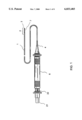
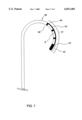
- FIG. 1 is an overall view of a catheter system having a flexible long electrode means at its distal tip section constructed in accordance with the principles of the present invention.
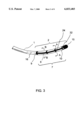
- FIG. 2 is a close-up view of the distal tip section of the catheter system comprising a flexible long electrode means and a cap electrode at the distal end having linear lesion capabilities.
- FIG. 3 is a perspective view of the electrode means of FIG. 2, wherein the wire of the flexible long electrode is located at the outermost portion of the deflectable catheter shaft of the present catheter system.
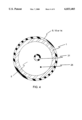
- FIG. 4 is a cross-sectional view of the ring electrode portion, section A--A, of the distal tip section of FIG. 3.
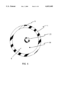
- FIG. 5 is a cross-sectional view of the non-ring electrode portion, section B--B, of the distal tip section of FIG. 3.
- FIG. 6 is a perspective view of FIG. 2, comprising a flexible long electrode means and a plurality of balloons at the distal tip section of the present catheter system.
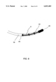
- FIG. 7 is a close-up view of the distal tip section of an alternate catheter system comprising a flexible long electrode means having a cap electrode at the distal end having linear lesion capabilities.
- FIG. 8 is a perspective view of the electrode means of FIG. 5, wherein the flexible long electrode is located at the outermost portion of the deflectable catheter shaft of the present catheter system.
- FIG. 1 shows an overall view of a catheter system having a flexible long electrode means at its distal tip section constructed in accordance with the principles of the present invention.
- a catheter system comprises a catheter shaft 1 having a distal tip section 2, a shaft distal end 3, a shaft proximal end 4, and at least one lumen 5 extending between the shaft distal end 3 and shaft proximal end 4.
- a handle 6 is attached to the shaft proximal end 4 of the catheter shaft 1, wherein the handle 6 has a cavity.
- a wire electrode means 7 is mounted on the distal tip section 2 of the catheter shaft 1.
- the electrode means 7 has a wire means 8 and a plurality of ring 9, 10, wherein the wire means 8 has a wire core section 11, a wire distal end 12 and a wire proximal end 13.
- a first ring 10 is secured to the wire distal end 12 and a second ring 9 is secured to the wire proximal end 13.
- the wire means can be a flat wire, a meshed wire, and the
- the handle has one optional uni-directional steering mechanism 22.
- the steering mechanism 22 is to deflect the tip section 2 of the catheter shaft 1 for catheter maneuvering and positioning. By deploying the steering mechanism 22, the distal tip section 2 of the catheter shaft 1 deflects to one direction. By un-deploying the steering mechanism 22, the tip section returns to its neutral position.
- the steering mechanism 22 at the handle 6 comprises means for providing a plurality of deflectable curves on the distal tip section 2 of the catheter shaft 1.
- the mechanism of an ablation catheter having multiple flexible curves is described by a patent application Ser. No. 08/763,614, filed Dec. 11, 1996, now U.S. Pat No. 5,782,828.
- FIG. 2 shows a close-up view of the distal tip section 2 of the catheter system comprising a flexible long electrode means 7 and a cap 15 at the distal end 2 having linear lesion capabilities.
- the catheter system has an unidirectional deflectability. Under a deployed state, an outermost portion 16 of the catheter shaft surfaces lies in exact opposite to an innermost portion 17 of the catheter shaft 1.
- the catheter system further comprises at least one third ring 14 of the plurality of ring electrodes, wherein the at least one third ring 14 is secured to the wire core section 11 of the electrode means 7.
- the wire is a flat wire.
- the catheter system further comprises a cap electrode 15 at the shaft distal end 2 of the catheter shaft.
- FIG. 3 shows a perspective view of the electrode means of FIG. 2, wherein the wire 8 of the flexible long electrode 7 is located at the outermost portion 16 of the deflectable catheter shaft of the present catheter system.
- FIG. 4 shows a cross-sectional view of the ring electrode portion, section A--A of FIG. 3, of the distal tip section 2 of the catheter shaft 1.
- the ring 9, 10 or 14 covers a majority of the circumference of the catheter shaft I.
- FIG. 5 shows a cross-sectional view of the non-ring electrode portion, section B--B of FIG. 3, of the distal tip section 2 of the catheter shaft 1.
- the core wire portion 11 of the wire 8 of the electrode means 7 stays intimately onto the shaft surface.
- a fluid conveying passageway 31 is associated with the catheter shaft 1, and is preferably disposed within the lumen 5 of the catheter shaft 1 along the longitudinal axis thereof.
- the fluid conveying passageway is adapted to communicate with a fluid supply source (not shown) to convey fluid from the source and through said passageway to be discharged out of the tip section 2 at an opening 32.
- the fluid flow rate from the fluid infusion mechanism may be between approximately 5 ml/min to 20 ml/min.
- the electrodes are formed of conducting materials selected from the group of platinum, iridium, gold, silver, stainless steel, and Nitinol.
- FIG. 6 shows a perspective view of the distal tip section 2 of an alternate catheter system comprising a plurality of balloons 50, 51 when deployed and a flexible long electrode 7 and a cap electrode 15.
- the balloons are made of materials selected from the group of compliant and non-compliant plastics, such as polyethylene, polyethylene terephthalate, polypropylene, nylon and the like.
- the catheter system comprises a catheter shaft 1 having a distal tip section 2, a shaft distal end 3, a shaft proximal end 4, and at least one lumen 5 extending between the shaft distal end 3 and shaft proximal end 4.
- a handle 6 is attached to the shaft proximal end 4 of the catheter shaft 1.
- the handle 6 has a cavity.
- the wire electrode means 7 has a wire 8, and at least one proximal ring 52 and one distal ring 53, the wire having a wire core section 54, a wire distal end 55 and a wire proximal end 56, wherein the at the least one proximal ring electrode 52 is secured to the wire proximal end 56 and the at least one distal ring 53 is secured to the wire distal end 55.
- the balloons are deployable by a fluid infusion/suction controller at the handle 6, wherein the balloons are used to block and isolate the region for ablation purposes.
- FIG. 7 shows a close-up view of the distal tip section 2 of an alternate catheter system comprising a flexible long electrode means having a cap electrode at the distal end having linear lesion capabilities.
- the catheter system comprises a catheter shaft 1 having a distal tip section 2, a shaft distal end 3, a shaft proximal end 4, and at least one lumen 5 extending between the shaft distal end 3 and shaft proximal end 4.
- a handle 6 is attached to the shaft proximal end 4 of the catheter shaft 1.
- the handle 6 has a cavity.
- a wire electrode means 57 is mounted on the distal tip section 2 of the catheter shaft 1.
- the electrode means has a wire 8, a cap 45, and at least one ring 49, the wire having a wire core section 42, a wire distal end 43 and a wire proximal end 44, wherein the cap 45 is secured to the wire distal end 43 and the at least one ring 49 is secured to the wire proximal end 44.
- FIG. 8 shows a perspective view of the electrode means of FIG. 7, wherein the wire 8 of the electrode means 57 is located at the outermost portion 58 of the deflectable catheter shaft of the present catheter system.
- the at least one ring electrode 9 or 10 has an insulated conducting wire (not shown) secured to the ring, which passes through the lumen of the catheter shaft 1 and is soldered to a contact pin of the connector 21 at the proximal end of the handle 6.
- the conducting wire from the end of the connector is externally connected to an EKG monitor for diagnosis or to a RF generator during an electrophysiology ablation procedure. Therefrom, the RF current is transmitted through the conducting wire to the electrode and the RF current is delivered to the target tissue for a true linear lesion.
- a temperature sensor 24, either a thermocouple means or a thermister means, is constructed at the proximity of the electrode 9 or 10 to measure the tissue contact temperature when RF energy is delivered.
- the temperature sensing wire 25 from the thermocouple or thermister is connected to one of the contact pins (not shown) of the connector 21 and externally connected to a transducer and to a temperature controller.
- the temperature reading is thereafter relayed to a closed-loop control mechanism to adjust the RF energy output.
- the RF energy delivered is thus controlled by the temperature sensor reading or by a pre-programmed control algorithm.
- the catheter of this invention is meant to provide fluid communication and commensurate flow of fluid originating inside the tip section of the catheter shaft to the electrode exterior surface, which directs the fluid flow from inside the catheter shaft over the exterior surface of the electrode to provide a fluid protective layer surrounding the electrode to minimize temperature elevation of the electrode with biological tissues.
Abstract
Description
Claims (20)
Priority Applications (1)
| Application Number | Priority Date | Filing Date | Title |
|---|---|---|---|
| US09/168,575 US6033403A (en) | 1998-10-08 | 1998-10-08 | Long electrode catheter system and methods thereof |
Applications Claiming Priority (1)
| Application Number | Priority Date | Filing Date | Title |
|---|---|---|---|
| US09/168,575 US6033403A (en) | 1998-10-08 | 1998-10-08 | Long electrode catheter system and methods thereof |
Publications (1)
| Publication Number | Publication Date |
|---|---|
| US6033403A true US6033403A (en) | 2000-03-07 |
Family
ID=22612065
Family Applications (1)
| Application Number | Title | Priority Date | Filing Date |
|---|---|---|---|
| US09/168,575 Expired - Lifetime US6033403A (en) | 1998-10-08 | 1998-10-08 | Long electrode catheter system and methods thereof |
Country Status (1)
| Country | Link |
|---|---|
| US (1) | US6033403A (en) |
Cited By (81)
| Publication number | Priority date | Publication date | Assignee | Title |
|---|---|---|---|---|
| US6246913B1 (en) * | 1997-02-14 | 2001-06-12 | Oractec Interventions, Inc. | Method and apparatus for the treatment of strabismus |
| US6371955B1 (en) * | 1999-08-10 | 2002-04-16 | Biosense Webster, Inc. | Atrial branding iron catheter and a method for treating atrial fibrillation |
| US6430425B1 (en) * | 1999-08-16 | 2002-08-06 | Hans Jurgen Bisping | Electrode arrangement for medical catheters |
| US6464700B1 (en) | 1994-10-07 | 2002-10-15 | Scimed Life Systems, Inc. | Loop structures for positioning a diagnostic or therapeutic element on the epicardium or other organ surface |
| US6542781B1 (en) | 1999-11-22 | 2003-04-01 | Scimed Life Systems, Inc. | Loop structures for supporting diagnostic and therapeutic elements in contact with body tissue |
| US6610055B1 (en) * | 1997-10-10 | 2003-08-26 | Scimed Life Systems, Inc. | Surgical method for positioning a diagnostic or therapeutic element on the epicardium or other organ surface |
| US20040015164A1 (en) * | 2002-07-19 | 2004-01-22 | Fuimaono Kristine B. | Atrial ablation catheter and method for treating atrial fibrillation |
| US20040143258A1 (en) * | 1999-08-10 | 2004-07-22 | Biosense Webster, Inc. | Irrigation probe for ablation during open heart surgery |
| US20040167510A1 (en) * | 2003-02-20 | 2004-08-26 | Medwaves, Inc. | Preformed catheter set for use with a linear ablation system to produce ablation lines in the left and right atrium for treatment of atrial fibrillation |
| US20050004516A1 (en) * | 2003-07-02 | 2005-01-06 | Guy Vanney | Steerable and shapable catheter employing fluid force |
| US20050015083A1 (en) * | 1994-10-07 | 2005-01-20 | Scimed Life Systems, Inc. | Loop structures for positioning a diagnostic or therapeutic element on the epicardium or other organ surface |
| US20050273096A1 (en) * | 2004-05-27 | 2005-12-08 | Roop John A | Anchoring introducer sheath with distal slots for catheter delivery and translation |
| US20060106375A1 (en) * | 2004-11-15 | 2006-05-18 | Werneth Randell L | Ablation system with feedback |
| US20060142752A1 (en) * | 2001-11-29 | 2006-06-29 | Ormsby Theodore C | Radio-frequency-based catheter system with improved deflection and steering mechanisms |
| US20060142694A1 (en) * | 2004-12-28 | 2006-06-29 | Bednarek Michael C | Bi-directional steerable catheter control handle |
| US20060287650A1 (en) * | 2005-06-21 | 2006-12-21 | Hong Cao | Ablation catheter with fluid distribution structures |
| US20070016164A1 (en) * | 2005-06-28 | 2007-01-18 | Dudney Joshua L | Actuation handle for a catheter |
| US20070066972A1 (en) * | 2001-11-29 | 2007-03-22 | Medwaves, Inc. | Ablation catheter apparatus with one or more electrodes |
| US20070083195A1 (en) * | 2005-07-11 | 2007-04-12 | Werneth Randell L | Low power tissue ablation system |
| US20070250056A1 (en) * | 2003-07-02 | 2007-10-25 | Guy Vanney | Ablation fluid manifold for ablation catheter |
| US20070299424A1 (en) * | 2006-05-16 | 2007-12-27 | Sarah Cumming | Steerable catheter using flat pull wires and method of making same |
| US20080082099A1 (en) * | 2006-09-29 | 2008-04-03 | Duane Dickens | Surgical probe and methods for targeted treatment of heart structures |
| US20080103497A1 (en) * | 1998-07-07 | 2008-05-01 | Mulier Peter M | Method and apparatus for creating a bi-polar virtual electrode used for the ablation of tissue |
| US20080281312A1 (en) * | 2007-05-11 | 2008-11-13 | Ablation Frontiers, Inc. | Ablation Therapy System and Method for Treating Continuous Atrial Fibrillation |
| US20080306477A1 (en) * | 2004-11-24 | 2008-12-11 | Kunis Christopher G | Atrial ablation catheter and method of use |
| US20090030411A1 (en) * | 2004-10-14 | 2009-01-29 | Werneth Randell L | Ablation catheter |
| US7540870B2 (en) | 2006-08-08 | 2009-06-02 | Bacoustics, Llc | Ablative ultrasonic-cryogenic apparatus |
| US20090221955A1 (en) * | 2006-08-08 | 2009-09-03 | Bacoustics, Llc | Ablative ultrasonic-cryogenic methods |
| US7591784B2 (en) | 2005-04-26 | 2009-09-22 | St. Jude Medical, Atrial Fibrillation Division, Inc. | Bi-directional handle for a catheter |
| US20100168738A1 (en) * | 2008-12-31 | 2010-07-01 | Schneider Clinton W | Ablation devices, systems and method for measuring cooling effect of fluid flow |
| US20100174280A1 (en) * | 2007-06-14 | 2010-07-08 | Massimo Grimaldi | Catheter for percutaneous transcatheter ablation of cardiac arrhythmias using bipolar radiofrequency |
| US7819866B2 (en) | 2003-01-21 | 2010-10-26 | St. Jude Medical, Atrial Fibrillation Division, Inc. | Ablation catheter and electrode |
| US7850685B2 (en) | 2005-06-20 | 2010-12-14 | Medtronic Ablation Frontiers Llc | Ablation catheter |
| US20110130750A1 (en) * | 2009-11-30 | 2011-06-02 | Medwaves, Inc. | Radio frequency ablation system with tracking sensor |
| US8273285B2 (en) | 2005-01-10 | 2012-09-25 | St. Jude Medical, Atrial Fibrillation Division, Inc. | Steerable catheter and methods of making the same |
| US8328798B2 (en) | 1999-10-02 | 2012-12-11 | Quantumcor, Inc | Method for treating and repairing mitral valve annulus |
| US8583260B2 (en) | 2004-12-28 | 2013-11-12 | St. Jude Medical, Atrial Fibrillation Division, Inc. | Long travel steerable catheter actuator |
| US8657814B2 (en) | 2005-08-22 | 2014-02-25 | Medtronic Ablation Frontiers Llc | User interface for tissue ablation system |
| US8777929B2 (en) | 2005-06-28 | 2014-07-15 | St. Jude Medical, Atrial Fibrillation Division, Inc. | Auto lock for catheter handle |
| US20140303703A1 (en) * | 2008-11-12 | 2014-10-09 | Ecole Polytechnique Federale De Lausanne | Microfabricated neurostimulation device |
| US8974445B2 (en) | 2009-01-09 | 2015-03-10 | Recor Medical, Inc. | Methods and apparatus for treatment of cardiac valve insufficiency |
| US9005194B2 (en) | 2004-11-24 | 2015-04-14 | Medtronic Ablation Frontiers Llc | Atrial ablation catheter adapted for treatment of septal wall arrhythmogenic foci and method of use |
| EP2881057A1 (en) * | 2013-12-05 | 2015-06-10 | Region Nordjylland | Apparatus for creating linear lesions in body tissue within a body vessel |
| CN105935314A (en) * | 2016-06-17 | 2016-09-14 | 赵学 | Radiofrequency ablation catheter with multi-point mapping function |
| US9474894B2 (en) | 2014-08-27 | 2016-10-25 | Aleva Neurotherapeutics | Deep brain stimulation lead |
| US9549708B2 (en) | 2010-04-01 | 2017-01-24 | Ecole Polytechnique Federale De Lausanne | Device for interacting with neurological tissue and methods of making and using the same |
| US9572985B2 (en) | 2014-08-27 | 2017-02-21 | Aleva Neurotherapeutics | Method of manufacturing a thin film leadless neurostimulator |
| US9604055B2 (en) | 2009-12-01 | 2017-03-28 | Ecole Polytechnique Federale De Lausanne | Microfabricated surface neurostimulation device and methods of making and using the same |
| US9700372B2 (en) | 2002-07-01 | 2017-07-11 | Recor Medical, Inc. | Intraluminal methods of ablating nerve tissue |
| US9724170B2 (en) | 2012-08-09 | 2017-08-08 | University Of Iowa Research Foundation | Catheters, catheter systems, and methods for puncturing through a tissue structure and ablating a tissue region |
| US9925376B2 (en) | 2014-08-27 | 2018-03-27 | Aleva Neurotherapeutics | Treatment of autoimmune diseases with deep brain stimulation |
| US9987081B1 (en) | 2017-04-27 | 2018-06-05 | Iowa Approach, Inc. | Systems, devices, and methods for signal generation |
| US9999465B2 (en) | 2014-10-14 | 2018-06-19 | Iowa Approach, Inc. | Method and apparatus for rapid and safe pulmonary vein cardiac ablation |
| US10099036B2 (en) | 2006-05-16 | 2018-10-16 | St. Jude Medical, Atrial Fibrillation Division, Inc. | Steerable catheter using flat pull wires and having torque transfer layer made of braided flat wires |
| US10130423B1 (en) | 2017-07-06 | 2018-11-20 | Farapulse, Inc. | Systems, devices, and methods for focal ablation |
| US10166392B2 (en) | 2008-07-30 | 2019-01-01 | Ecole Polytechnique Federale De Lausanne | Apparatus and method for optimized stimulation of a neurological target |
| US10172673B2 (en) | 2016-01-05 | 2019-01-08 | Farapulse, Inc. | Systems devices, and methods for delivery of pulsed electric field ablative energy to endocardial tissue |
| US10183149B2 (en) | 2004-12-28 | 2019-01-22 | St. Jude Medical, Atrial Fibrillation Division, Inc. | Five degree of freedom ultrasound catheter and catheter control handle |
| US10322286B2 (en) | 2016-01-05 | 2019-06-18 | Farapulse, Inc. | Systems, apparatuses and methods for delivery of ablative energy to tissue |
| US10433906B2 (en) | 2014-06-12 | 2019-10-08 | Farapulse, Inc. | Method and apparatus for rapid and selective transurethral tissue ablation |
| US10507302B2 (en) | 2016-06-16 | 2019-12-17 | Farapulse, Inc. | Systems, apparatuses, and methods for guide wire delivery |
| US10512505B2 (en) | 2018-05-07 | 2019-12-24 | Farapulse, Inc. | Systems, apparatuses and methods for delivery of ablative energy to tissue |
| US10517672B2 (en) | 2014-01-06 | 2019-12-31 | Farapulse, Inc. | Apparatus and methods for renal denervation ablation |
| US10617867B2 (en) | 2017-04-28 | 2020-04-14 | Farapulse, Inc. | Systems, devices, and methods for delivery of pulsed electric field ablative energy to esophageal tissue |
| US10624693B2 (en) | 2014-06-12 | 2020-04-21 | Farapulse, Inc. | Method and apparatus for rapid and selective tissue ablation with cooling |
| US10625080B1 (en) | 2019-09-17 | 2020-04-21 | Farapulse, Inc. | Systems, apparatuses, and methods for detecting ectopic electrocardiogram signals during pulsed electric field ablation |
| US10660702B2 (en) | 2016-01-05 | 2020-05-26 | Farapulse, Inc. | Systems, devices, and methods for focal ablation |
| US10675443B2 (en) | 2016-03-07 | 2020-06-09 | St. Jude Medical, Cardiology Division, Inc. | Medical device including an actuator restraining assembly |
| US10687892B2 (en) | 2018-09-20 | 2020-06-23 | Farapulse, Inc. | Systems, apparatuses, and methods for delivery of pulsed electric field ablative energy to endocardial tissue |
| US10842572B1 (en) | 2019-11-25 | 2020-11-24 | Farapulse, Inc. | Methods, systems, and apparatuses for tracking ablation devices and generating lesion lines |
| US10893905B2 (en) | 2017-09-12 | 2021-01-19 | Farapulse, Inc. | Systems, apparatuses, and methods for ventricular focal ablation |
| WO2021024140A1 (en) * | 2019-08-02 | 2021-02-11 | St. Jude Medical, Cardiology Division, Inc. | Lesion predicting flex tip |
| US10966620B2 (en) | 2014-05-16 | 2021-04-06 | Aleva Neurotherapeutics Sa | Device for interacting with neurological tissue and methods of making and using the same |
| US11020180B2 (en) | 2018-05-07 | 2021-06-01 | Farapulse, Inc. | Epicardial ablation catheter |
| US11033236B2 (en) | 2018-05-07 | 2021-06-15 | Farapulse, Inc. | Systems, apparatuses, and methods for filtering high voltage noise induced by pulsed electric field ablation |
| US11065047B2 (en) | 2019-11-20 | 2021-07-20 | Farapulse, Inc. | Systems, apparatuses, and methods for protecting electronic components from high power noise induced by high voltage pulses |
| US11259869B2 (en) | 2014-05-07 | 2022-03-01 | Farapulse, Inc. | Methods and apparatus for selective tissue ablation |
| US11266830B2 (en) | 2018-03-02 | 2022-03-08 | Aleva Neurotherapeutics | Neurostimulation device |
| US11311718B2 (en) | 2014-05-16 | 2022-04-26 | Aleva Neurotherapeutics Sa | Device for interacting with neurological tissue and methods of making and using the same |
| US11432870B2 (en) | 2016-10-04 | 2022-09-06 | Avent, Inc. | Cooled RF probes |
| US11497541B2 (en) | 2019-11-20 | 2022-11-15 | Boston Scientific Scimed, Inc. | Systems, apparatuses, and methods for protecting electronic components from high power noise induced by high voltage pulses |
Citations (6)
| Publication number | Priority date | Publication date | Assignee | Title |
|---|---|---|---|---|
| US4532924A (en) * | 1980-05-13 | 1985-08-06 | American Hospital Supply Corporation | Multipolar electrosurgical device and method |
| US5766171A (en) * | 1994-02-09 | 1998-06-16 | Keravision, Inc. | Electrosurgical procedure for the treatment of the cornea |
| US5863291A (en) * | 1996-04-08 | 1999-01-26 | Cardima, Inc. | Linear ablation assembly |
| US5921924A (en) * | 1993-12-03 | 1999-07-13 | Avitall; Boaz | Mapping and ablation catheter system utilizing multiple control elements |
| US5921982A (en) * | 1993-07-30 | 1999-07-13 | Lesh; Michael D. | Systems and methods for ablating body tissue |
| US5938660A (en) * | 1997-06-27 | 1999-08-17 | Daig Corporation | Process and device for the treatment of atrial arrhythmia |
-
1998
- 1998-10-08 US US09/168,575 patent/US6033403A/en not_active Expired - Lifetime
Patent Citations (6)
| Publication number | Priority date | Publication date | Assignee | Title |
|---|---|---|---|---|
| US4532924A (en) * | 1980-05-13 | 1985-08-06 | American Hospital Supply Corporation | Multipolar electrosurgical device and method |
| US5921982A (en) * | 1993-07-30 | 1999-07-13 | Lesh; Michael D. | Systems and methods for ablating body tissue |
| US5921924A (en) * | 1993-12-03 | 1999-07-13 | Avitall; Boaz | Mapping and ablation catheter system utilizing multiple control elements |
| US5766171A (en) * | 1994-02-09 | 1998-06-16 | Keravision, Inc. | Electrosurgical procedure for the treatment of the cornea |
| US5863291A (en) * | 1996-04-08 | 1999-01-26 | Cardima, Inc. | Linear ablation assembly |
| US5938660A (en) * | 1997-06-27 | 1999-08-17 | Daig Corporation | Process and device for the treatment of atrial arrhythmia |
Cited By (171)
| Publication number | Priority date | Publication date | Assignee | Title |
|---|---|---|---|---|
| US7175619B2 (en) | 1994-10-07 | 2007-02-13 | Boston Scientific Scimed, Inc. | Loop structures for positioning a diagnostic or therapeutic element on the epicardium or other organ surface |
| US6464700B1 (en) | 1994-10-07 | 2002-10-15 | Scimed Life Systems, Inc. | Loop structures for positioning a diagnostic or therapeutic element on the epicardium or other organ surface |
| US20050015083A1 (en) * | 1994-10-07 | 2005-01-20 | Scimed Life Systems, Inc. | Loop structures for positioning a diagnostic or therapeutic element on the epicardium or other organ surface |
| US6246913B1 (en) * | 1997-02-14 | 2001-06-12 | Oractec Interventions, Inc. | Method and apparatus for the treatment of strabismus |
| US6610055B1 (en) * | 1997-10-10 | 2003-08-26 | Scimed Life Systems, Inc. | Surgical method for positioning a diagnostic or therapeutic element on the epicardium or other organ surface |
| US9113896B2 (en) * | 1998-07-07 | 2015-08-25 | Medtronic, Inc. | Method and apparatus for creating a bi-polar virtual electrode used for the ablation of tissue |
| US20080103497A1 (en) * | 1998-07-07 | 2008-05-01 | Mulier Peter M | Method and apparatus for creating a bi-polar virtual electrode used for the ablation of tissue |
| US20080015570A1 (en) * | 1998-12-14 | 2008-01-17 | Ormsby Theodore C | Hollow conductive coaxial cable for radio frequency based tissue ablation system |
| US8308722B2 (en) | 1998-12-14 | 2012-11-13 | Medwaves, Inc. | Hollow conductive coaxial cable for radio frequency based tissue ablation system |
| US8160693B2 (en) | 1999-08-10 | 2012-04-17 | Biosense Webster, Inc. | Irrigation probe for ablation during open heart surgery |
| US20040153134A1 (en) * | 1999-08-10 | 2004-08-05 | Fuimaono Kristine B. | Irrigation probe for ablation during open heart surgery |
| US20040143258A1 (en) * | 1999-08-10 | 2004-07-22 | Biosense Webster, Inc. | Irrigation probe for ablation during open heart surgery |
| US6852120B1 (en) * | 1999-08-10 | 2005-02-08 | Biosense Webster, Inc | Irrigation probe for ablation during open heart surgery |
| US7764994B2 (en) | 1999-08-10 | 2010-07-27 | Biosense Webster, Inc. | Irrigation probe for ablation during open heart surgery |
| US7761148B2 (en) | 1999-08-10 | 2010-07-20 | Biosense Webster, Inc. | Irrigation probe for ablation during open heart surgery |
| US6371955B1 (en) * | 1999-08-10 | 2002-04-16 | Biosense Webster, Inc. | Atrial branding iron catheter and a method for treating atrial fibrillation |
| US6430425B1 (en) * | 1999-08-16 | 2002-08-06 | Hans Jurgen Bisping | Electrode arrangement for medical catheters |
| US8328798B2 (en) | 1999-10-02 | 2012-12-11 | Quantumcor, Inc | Method for treating and repairing mitral valve annulus |
| US6542781B1 (en) | 1999-11-22 | 2003-04-01 | Scimed Life Systems, Inc. | Loop structures for supporting diagnostic and therapeutic elements in contact with body tissue |
| US7815637B2 (en) | 2001-11-29 | 2010-10-19 | Ormsby Theodore C | Radio-frequency-based catheter system with improved deflection and steering mechanisms |
| US20060142752A1 (en) * | 2001-11-29 | 2006-06-29 | Ormsby Theodore C | Radio-frequency-based catheter system with improved deflection and steering mechanisms |
| US8152799B2 (en) | 2001-11-29 | 2012-04-10 | Medwaves, Inc. | Radio frequency-based catheter system with improved deflection and steering mechanisms |
| US20070066972A1 (en) * | 2001-11-29 | 2007-03-22 | Medwaves, Inc. | Ablation catheter apparatus with one or more electrodes |
| US20110009858A1 (en) * | 2001-11-29 | 2011-01-13 | Medwaves, Inc. | Radio frequency-based catheter system with improved deflection and steering mechanisms |
| US9700372B2 (en) | 2002-07-01 | 2017-07-11 | Recor Medical, Inc. | Intraluminal methods of ablating nerve tissue |
| US9707034B2 (en) | 2002-07-01 | 2017-07-18 | Recor Medical, Inc. | Intraluminal method and apparatus for ablating nerve tissue |
| US20050119651A1 (en) * | 2002-07-19 | 2005-06-02 | Biosense Webster, Inc. | Atrial ablation catheter and method for treating atrial fibrillation |
| US20040015164A1 (en) * | 2002-07-19 | 2004-01-22 | Fuimaono Kristine B. | Atrial ablation catheter and method for treating atrial fibrillation |
| US7588568B2 (en) * | 2002-07-19 | 2009-09-15 | Biosense Webster, Inc. | Atrial ablation catheter and method for treating atrial fibrillation |
| US7727230B2 (en) | 2002-07-19 | 2010-06-01 | Biosense-Webster, Inc. | Atrial ablation catheter and method for treating atrial fibrillation |
| US7819866B2 (en) | 2003-01-21 | 2010-10-26 | St. Jude Medical, Atrial Fibrillation Division, Inc. | Ablation catheter and electrode |
| US20040167510A1 (en) * | 2003-02-20 | 2004-08-26 | Medwaves, Inc. | Preformed catheter set for use with a linear ablation system to produce ablation lines in the left and right atrium for treatment of atrial fibrillation |
| US6941953B2 (en) * | 2003-02-20 | 2005-09-13 | Medwaves, Inc. | Preformed catheter set for use with a linear ablation system to produce ablation lines in the left and right atrium for treatment of atrial fibrillation |
| US20070250056A1 (en) * | 2003-07-02 | 2007-10-25 | Guy Vanney | Ablation fluid manifold for ablation catheter |
| US20050004516A1 (en) * | 2003-07-02 | 2005-01-06 | Guy Vanney | Steerable and shapable catheter employing fluid force |
| US20060258978A1 (en) * | 2003-07-02 | 2006-11-16 | St. Jude Medical, Atrial Fibrillation Division, Inc. | Steerable and shapable catheter employing fluid force |
| US20050273096A1 (en) * | 2004-05-27 | 2005-12-08 | Roop John A | Anchoring introducer sheath with distal slots for catheter delivery and translation |
| US20090030411A1 (en) * | 2004-10-14 | 2009-01-29 | Werneth Randell L | Ablation catheter |
| US8486063B2 (en) | 2004-10-14 | 2013-07-16 | Medtronic Ablation Frontiers Llc | Ablation catheter |
| US9642675B2 (en) | 2004-10-14 | 2017-05-09 | Medtronic Ablation Frontiers Llc | Ablation catheter |
| US20060106375A1 (en) * | 2004-11-15 | 2006-05-18 | Werneth Randell L | Ablation system with feedback |
| US8617152B2 (en) | 2004-11-15 | 2013-12-31 | Medtronic Ablation Frontiers Llc | Ablation system with feedback |
| US8273084B2 (en) | 2004-11-24 | 2012-09-25 | Medtronic Ablation Frontiers Llc | Atrial ablation catheter and method of use |
| US20080306477A1 (en) * | 2004-11-24 | 2008-12-11 | Kunis Christopher G | Atrial ablation catheter and method of use |
| US9005194B2 (en) | 2004-11-24 | 2015-04-14 | Medtronic Ablation Frontiers Llc | Atrial ablation catheter adapted for treatment of septal wall arrhythmogenic foci and method of use |
| US10960181B2 (en) | 2004-12-28 | 2021-03-30 | St. Jude Medical, Atrial Fibrillation Division, Inc. | Fixed dimensional and bi-directional steerable catheter control handle |
| US10183149B2 (en) | 2004-12-28 | 2019-01-22 | St. Jude Medical, Atrial Fibrillation Division, Inc. | Five degree of freedom ultrasound catheter and catheter control handle |
| US10035000B2 (en) | 2004-12-28 | 2018-07-31 | St. Jude Medical, Atrial Fibrillation Division, Inc. | Fixed dimensional and bi-directional steerable catheter control handle |
| US7691095B2 (en) | 2004-12-28 | 2010-04-06 | St. Jude Medical, Atrial Fibrillation Division, Inc. | Bi-directional steerable catheter control handle |
| US20060142694A1 (en) * | 2004-12-28 | 2006-06-29 | Bednarek Michael C | Bi-directional steerable catheter control handle |
| US9132258B2 (en) | 2004-12-28 | 2015-09-15 | St. Jude Medical, Atrial Fibrillation Division, Inc. | Fixed dimensional and bi-directional steerable catheter control handle |
| US8583260B2 (en) | 2004-12-28 | 2013-11-12 | St. Jude Medical, Atrial Fibrillation Division, Inc. | Long travel steerable catheter actuator |
| US10022521B2 (en) | 2004-12-28 | 2018-07-17 | St. Jude Medical, Atrial Fibrillation Division, Inc. | Long travel steerable catheter actuator |
| US10493708B2 (en) | 2005-01-10 | 2019-12-03 | St. Jude Medical, Atrial Fibrillation Division, Inc. | Steerable catheter and methods of making the same |
| US8273285B2 (en) | 2005-01-10 | 2012-09-25 | St. Jude Medical, Atrial Fibrillation Division, Inc. | Steerable catheter and methods of making the same |
| US20100004592A1 (en) * | 2005-04-26 | 2010-01-07 | William Emerson Butler | Bi-directional handle for a catheter |
| US7591784B2 (en) | 2005-04-26 | 2009-09-22 | St. Jude Medical, Atrial Fibrillation Division, Inc. | Bi-directional handle for a catheter |
| US8177711B2 (en) | 2005-04-26 | 2012-05-15 | St. Jude Medical, Atrial Fbrillation Division, Inc. | Bi-directional handle for a catheter |
| US8979740B2 (en) | 2005-04-26 | 2015-03-17 | St. Jude Medical, Atrial Fibrillation Division, Inc. | Bi-directional handle for a catheter |
| US9468495B2 (en) | 2005-06-20 | 2016-10-18 | Medtronic Ablation Frontiers Llc | Ablation catheter |
| US8979841B2 (en) | 2005-06-20 | 2015-03-17 | Medtronic Ablation Frontiers Llc | Ablation catheter |
| US8771267B2 (en) | 2005-06-20 | 2014-07-08 | Medtronic Ablation Frontiers Llc | Ablation catheter |
| US20110106074A1 (en) * | 2005-06-20 | 2011-05-05 | Medtronic Ablation Frontiers Llc | Ablation catheter |
| US8337492B2 (en) | 2005-06-20 | 2012-12-25 | Medtronic Ablation Frontiers Llc | Ablation catheter |
| US7850685B2 (en) | 2005-06-20 | 2010-12-14 | Medtronic Ablation Frontiers Llc | Ablation catheter |
| US20060287650A1 (en) * | 2005-06-21 | 2006-12-21 | Hong Cao | Ablation catheter with fluid distribution structures |
| US7819868B2 (en) | 2005-06-21 | 2010-10-26 | St. Jude Medical, Atrial Fibrilation Division, Inc. | Ablation catheter with fluid distribution structures |
| US7465288B2 (en) | 2005-06-28 | 2008-12-16 | St. Jude Medical, Atrial Fibrillation Division, Inc. | Actuation handle for a catheter |
| US20070016164A1 (en) * | 2005-06-28 | 2007-01-18 | Dudney Joshua L | Actuation handle for a catheter |
| US9694159B2 (en) | 2005-06-28 | 2017-07-04 | St. Jude Medical, Atrial Fibrillation Division, Inc. | Auto lock for catheter handle |
| US10737062B2 (en) | 2005-06-28 | 2020-08-11 | St. Jude Medical, Atrial Fibrillation Division, Inc. | Auto lock for catheter handle |
| US8777929B2 (en) | 2005-06-28 | 2014-07-15 | St. Jude Medical, Atrial Fibrillation Division, Inc. | Auto lock for catheter handle |
| US20070083195A1 (en) * | 2005-07-11 | 2007-04-12 | Werneth Randell L | Low power tissue ablation system |
| US8834461B2 (en) | 2005-07-11 | 2014-09-16 | Medtronic Ablation Frontiers Llc | Low power tissue ablation system |
| US9566113B2 (en) | 2005-07-11 | 2017-02-14 | Medtronic Ablation Frontiers Llc | Low power tissue ablation system |
| US8657814B2 (en) | 2005-08-22 | 2014-02-25 | Medtronic Ablation Frontiers Llc | User interface for tissue ablation system |
| US20070299424A1 (en) * | 2006-05-16 | 2007-12-27 | Sarah Cumming | Steerable catheter using flat pull wires and method of making same |
| US10099036B2 (en) | 2006-05-16 | 2018-10-16 | St. Jude Medical, Atrial Fibrillation Division, Inc. | Steerable catheter using flat pull wires and having torque transfer layer made of braided flat wires |
| US10912923B2 (en) | 2006-05-16 | 2021-02-09 | St. Jude Medical, Atrial Fibrillation Division, Inc. | Steerable catheter using flat pull wires and having torque transfer layer made of braided flat wires |
| US20080234660A2 (en) * | 2006-05-16 | 2008-09-25 | Sarah Cumming | Steerable Catheter Using Flat Pull Wires and Method of Making Same |
| US8062289B2 (en) | 2006-08-08 | 2011-11-22 | Bacoustics, Llc | Ablative ultrasonic-cryogenic apparatus |
| US20090221955A1 (en) * | 2006-08-08 | 2009-09-03 | Bacoustics, Llc | Ablative ultrasonic-cryogenic methods |
| US20090209885A1 (en) * | 2006-08-08 | 2009-08-20 | Bacoustics, Llc | Ablative ultrasonic-cryogenic apparatus |
| US7540870B2 (en) | 2006-08-08 | 2009-06-02 | Bacoustics, Llc | Ablative ultrasonic-cryogenic apparatus |
| US8187266B2 (en) | 2006-09-29 | 2012-05-29 | Quantumcor, Inc. | Surgical probe and methods for targeted treatment of heart structures |
| US20080082099A1 (en) * | 2006-09-29 | 2008-04-03 | Duane Dickens | Surgical probe and methods for targeted treatment of heart structures |
| US10219857B2 (en) | 2007-05-11 | 2019-03-05 | Medtronic Ablation Frontiers Llc | RF energy delivery system |
| US20080281312A1 (en) * | 2007-05-11 | 2008-11-13 | Ablation Frontiers, Inc. | Ablation Therapy System and Method for Treating Continuous Atrial Fibrillation |
| US8641704B2 (en) | 2007-05-11 | 2014-02-04 | Medtronic Ablation Frontiers Llc | Ablation therapy system and method for treating continuous atrial fibrillation |
| US8771269B2 (en) | 2007-05-11 | 2014-07-08 | Medtronic Ablation Frontiers Llc | RF energy delivery system and method |
| US9333030B2 (en) | 2007-06-14 | 2016-05-10 | Massimo Grimaldi | Catheter for percutaneous transcatheter ablation of cardiac arrhythmias using bipolar radiofrequency |
| US20100174280A1 (en) * | 2007-06-14 | 2010-07-08 | Massimo Grimaldi | Catheter for percutaneous transcatheter ablation of cardiac arrhythmias using bipolar radiofrequency |
| US9033980B2 (en) * | 2007-06-14 | 2015-05-19 | Massimo Grimaldi | Catheter for percutaneous transcatheter ablation of cardiac arrhythmias using bipolar radiofrequency |
| US10166392B2 (en) | 2008-07-30 | 2019-01-01 | Ecole Polytechnique Federale De Lausanne | Apparatus and method for optimized stimulation of a neurological target |
| US10952627B2 (en) | 2008-07-30 | 2021-03-23 | Ecole Polytechnique Federale De Lausanne | Apparatus and method for optimized stimulation of a neurological target |
| US20140303703A1 (en) * | 2008-11-12 | 2014-10-09 | Ecole Polytechnique Federale De Lausanne | Microfabricated neurostimulation device |
| US11123548B2 (en) | 2008-11-12 | 2021-09-21 | Ecole Polytechnique Federale De Lausanne | Microfabricated neurostimulation device |
| US9440082B2 (en) * | 2008-11-12 | 2016-09-13 | Ecole Polytechnique Federale De Lausanne | Microfabricated neurostimulation device |
| US10406350B2 (en) * | 2008-11-12 | 2019-09-10 | Ecole Polytechnique Federale De Lausanne | Microfabricated neurostimulation device |
| US20160287863A1 (en) * | 2008-11-12 | 2016-10-06 | Ecole Polytechnique Federale De Lausanne | Microfabricated neurostimulation device |
| US20100168738A1 (en) * | 2008-12-31 | 2010-07-01 | Schneider Clinton W | Ablation devices, systems and method for measuring cooling effect of fluid flow |
| US9320565B2 (en) | 2008-12-31 | 2016-04-26 | St. Jude Medical, Atrial Fibrillation Division, Inc. | Ablation devices, systems and method for measuring cooling effect of fluid flow |
| US8974445B2 (en) | 2009-01-09 | 2015-03-10 | Recor Medical, Inc. | Methods and apparatus for treatment of cardiac valve insufficiency |
| US20110130750A1 (en) * | 2009-11-30 | 2011-06-02 | Medwaves, Inc. | Radio frequency ablation system with tracking sensor |
| US9039698B2 (en) | 2009-11-30 | 2015-05-26 | Medwaves, Inc. | Radio frequency ablation system with tracking sensor |
| US9604055B2 (en) | 2009-12-01 | 2017-03-28 | Ecole Polytechnique Federale De Lausanne | Microfabricated surface neurostimulation device and methods of making and using the same |
| US11766560B2 (en) | 2010-04-01 | 2023-09-26 | Ecole Polytechnique Federale De Lausanne | Device for interacting with neurological tissue and methods of making and using the same |
| US9549708B2 (en) | 2010-04-01 | 2017-01-24 | Ecole Polytechnique Federale De Lausanne | Device for interacting with neurological tissue and methods of making and using the same |
| US9861802B2 (en) | 2012-08-09 | 2018-01-09 | University Of Iowa Research Foundation | Catheters, catheter systems, and methods for puncturing through a tissue structure |
| US11426573B2 (en) | 2012-08-09 | 2022-08-30 | University Of Iowa Research Foundation | Catheters, catheter systems, and methods for puncturing through a tissue structure and ablating a tissue region |
| US9724170B2 (en) | 2012-08-09 | 2017-08-08 | University Of Iowa Research Foundation | Catheters, catheter systems, and methods for puncturing through a tissue structure and ablating a tissue region |
| WO2015082696A1 (en) * | 2013-12-05 | 2015-06-11 | Region Nordjylland | Apparatus for creating linear lesions in body tissue within a body vessel |
| EP2881057A1 (en) * | 2013-12-05 | 2015-06-10 | Region Nordjylland | Apparatus for creating linear lesions in body tissue within a body vessel |
| US10517672B2 (en) | 2014-01-06 | 2019-12-31 | Farapulse, Inc. | Apparatus and methods for renal denervation ablation |
| US11589919B2 (en) | 2014-01-06 | 2023-02-28 | Boston Scientific Scimed, Inc. | Apparatus and methods for renal denervation ablation |
| US11259869B2 (en) | 2014-05-07 | 2022-03-01 | Farapulse, Inc. | Methods and apparatus for selective tissue ablation |
| US11311718B2 (en) | 2014-05-16 | 2022-04-26 | Aleva Neurotherapeutics Sa | Device for interacting with neurological tissue and methods of making and using the same |
| US10966620B2 (en) | 2014-05-16 | 2021-04-06 | Aleva Neurotherapeutics Sa | Device for interacting with neurological tissue and methods of making and using the same |
| US11241282B2 (en) | 2014-06-12 | 2022-02-08 | Boston Scientific Scimed, Inc. | Method and apparatus for rapid and selective transurethral tissue ablation |
| US10624693B2 (en) | 2014-06-12 | 2020-04-21 | Farapulse, Inc. | Method and apparatus for rapid and selective tissue ablation with cooling |
| US10433906B2 (en) | 2014-06-12 | 2019-10-08 | Farapulse, Inc. | Method and apparatus for rapid and selective transurethral tissue ablation |
| US11622803B2 (en) | 2014-06-12 | 2023-04-11 | Boston Scientific Scimed, Inc. | Method and apparatus for rapid and selective tissue ablation with cooling |
| US11730953B2 (en) | 2014-08-27 | 2023-08-22 | Aleva Neurotherapeutics | Deep brain stimulation lead |
| US10065031B2 (en) | 2014-08-27 | 2018-09-04 | Aleva Neurotherapeutics | Deep brain stimulation lead |
| US11167126B2 (en) | 2014-08-27 | 2021-11-09 | Aleva Neurotherapeutics | Deep brain stimulation lead |
| US9474894B2 (en) | 2014-08-27 | 2016-10-25 | Aleva Neurotherapeutics | Deep brain stimulation lead |
| US9925376B2 (en) | 2014-08-27 | 2018-03-27 | Aleva Neurotherapeutics | Treatment of autoimmune diseases with deep brain stimulation |
| US10441779B2 (en) | 2014-08-27 | 2019-10-15 | Aleva Neurotherapeutics | Deep brain stimulation lead |
| US9889304B2 (en) | 2014-08-27 | 2018-02-13 | Aleva Neurotherapeutics | Leadless neurostimulator |
| US9572985B2 (en) | 2014-08-27 | 2017-02-21 | Aleva Neurotherapeutics | Method of manufacturing a thin film leadless neurostimulator |
| US10201707B2 (en) | 2014-08-27 | 2019-02-12 | Aleva Neurotherapeutics | Treatment of autoimmune diseases with deep brain stimulation |
| US9999465B2 (en) | 2014-10-14 | 2018-06-19 | Iowa Approach, Inc. | Method and apparatus for rapid and safe pulmonary vein cardiac ablation |
| US10835314B2 (en) | 2014-10-14 | 2020-11-17 | Farapulse, Inc. | Method and apparatus for rapid and safe pulmonary vein cardiac ablation |
| US10172673B2 (en) | 2016-01-05 | 2019-01-08 | Farapulse, Inc. | Systems devices, and methods for delivery of pulsed electric field ablative energy to endocardial tissue |
| US10512779B2 (en) | 2016-01-05 | 2019-12-24 | Farapulse, Inc. | Systems, apparatuses and methods for delivery of ablative energy to tissue |
| US10709891B2 (en) | 2016-01-05 | 2020-07-14 | Farapulse, Inc. | Systems, apparatuses and methods for delivery of ablative energy to tissue |
| US11589921B2 (en) | 2016-01-05 | 2023-02-28 | Boston Scientific Scimed, Inc. | Systems, apparatuses and methods for delivery of ablative energy to tissue |
| US10322286B2 (en) | 2016-01-05 | 2019-06-18 | Farapulse, Inc. | Systems, apparatuses and methods for delivery of ablative energy to tissue |
| US10433908B2 (en) | 2016-01-05 | 2019-10-08 | Farapulse, Inc. | Systems, devices, and methods for delivery of pulsed electric field ablative energy to endocardial tissue |
| US10842561B2 (en) | 2016-01-05 | 2020-11-24 | Farapulse, Inc. | Systems, devices, and methods for delivery of pulsed electric field ablative energy to endocardial tissue |
| US11020179B2 (en) | 2016-01-05 | 2021-06-01 | Farapulse, Inc. | Systems, devices, and methods for focal ablation |
| US10660702B2 (en) | 2016-01-05 | 2020-05-26 | Farapulse, Inc. | Systems, devices, and methods for focal ablation |
| US10675443B2 (en) | 2016-03-07 | 2020-06-09 | St. Jude Medical, Cardiology Division, Inc. | Medical device including an actuator restraining assembly |
| US11517714B2 (en) | 2016-03-07 | 2022-12-06 | St. Jude Medical, Cardiology Division, Inc. | Medical device including an actuator restraining assembly |
| US10507302B2 (en) | 2016-06-16 | 2019-12-17 | Farapulse, Inc. | Systems, apparatuses, and methods for guide wire delivery |
| CN105935314A (en) * | 2016-06-17 | 2016-09-14 | 赵学 | Radiofrequency ablation catheter with multi-point mapping function |
| US11432870B2 (en) | 2016-10-04 | 2022-09-06 | Avent, Inc. | Cooled RF probes |
| US10016232B1 (en) | 2017-04-27 | 2018-07-10 | Iowa Approach, Inc. | Systems, devices, and methods for signal generation |
| US9987081B1 (en) | 2017-04-27 | 2018-06-05 | Iowa Approach, Inc. | Systems, devices, and methods for signal generation |
| US11357978B2 (en) | 2017-04-27 | 2022-06-14 | Boston Scientific Scimed, Inc. | Systems, devices, and methods for signal generation |
| US11833350B2 (en) | 2017-04-28 | 2023-12-05 | Boston Scientific Scimed, Inc. | Systems, devices, and methods for delivery of pulsed electric field ablative energy to esophageal tissue |
| US10617867B2 (en) | 2017-04-28 | 2020-04-14 | Farapulse, Inc. | Systems, devices, and methods for delivery of pulsed electric field ablative energy to esophageal tissue |
| US10130423B1 (en) | 2017-07-06 | 2018-11-20 | Farapulse, Inc. | Systems, devices, and methods for focal ablation |
| US10617467B2 (en) | 2017-07-06 | 2020-04-14 | Farapulse, Inc. | Systems, devices, and methods for focal ablation |
| US10893905B2 (en) | 2017-09-12 | 2021-01-19 | Farapulse, Inc. | Systems, apparatuses, and methods for ventricular focal ablation |
| US11738192B2 (en) | 2018-03-02 | 2023-08-29 | Aleva Neurotherapeutics | Neurostimulation device |
| US11266830B2 (en) | 2018-03-02 | 2022-03-08 | Aleva Neurotherapeutics | Neurostimulation device |
| US11020180B2 (en) | 2018-05-07 | 2021-06-01 | Farapulse, Inc. | Epicardial ablation catheter |
| US10512505B2 (en) | 2018-05-07 | 2019-12-24 | Farapulse, Inc. | Systems, apparatuses and methods for delivery of ablative energy to tissue |
| US10709502B2 (en) | 2018-05-07 | 2020-07-14 | Farapulse, Inc. | Systems, apparatuses and methods for delivery of ablative energy to tissue |
| US11033236B2 (en) | 2018-05-07 | 2021-06-15 | Farapulse, Inc. | Systems, apparatuses, and methods for filtering high voltage noise induced by pulsed electric field ablation |
| US10687892B2 (en) | 2018-09-20 | 2020-06-23 | Farapulse, Inc. | Systems, apparatuses, and methods for delivery of pulsed electric field ablative energy to endocardial tissue |
| WO2021024140A1 (en) * | 2019-08-02 | 2021-02-11 | St. Jude Medical, Cardiology Division, Inc. | Lesion predicting flex tip |
| US11738200B2 (en) | 2019-09-17 | 2023-08-29 | Boston Scientific Scimed, Inc. | Systems, apparatuses, and methods for detecting ectopic electrocardiogram signals during pulsed electric field ablation |
| US10688305B1 (en) | 2019-09-17 | 2020-06-23 | Farapulse, Inc. | Systems, apparatuses, and methods for detecting ectopic electrocardiogram signals during pulsed electric field ablation |
| US10625080B1 (en) | 2019-09-17 | 2020-04-21 | Farapulse, Inc. | Systems, apparatuses, and methods for detecting ectopic electrocardiogram signals during pulsed electric field ablation |
| US11684408B2 (en) | 2019-11-20 | 2023-06-27 | Boston Scientific Scimed, Inc. | Systems, apparatuses, and methods for protecting electronic components from high power noise induced by high voltage pulses |
| US11497541B2 (en) | 2019-11-20 | 2022-11-15 | Boston Scientific Scimed, Inc. | Systems, apparatuses, and methods for protecting electronic components from high power noise induced by high voltage pulses |
| US11065047B2 (en) | 2019-11-20 | 2021-07-20 | Farapulse, Inc. | Systems, apparatuses, and methods for protecting electronic components from high power noise induced by high voltage pulses |
| US11931090B2 (en) | 2019-11-20 | 2024-03-19 | Boston Scientific Scimed, Inc. | Systems, apparatuses, and methods for protecting electronic components from high power noise induced by high voltage pulses |
| US10842572B1 (en) | 2019-11-25 | 2020-11-24 | Farapulse, Inc. | Methods, systems, and apparatuses for tracking ablation devices and generating lesion lines |
Similar Documents
| Publication | Publication Date | Title |
|---|---|---|
| US6033403A (en) | Long electrode catheter system and methods thereof | |
| US6217576B1 (en) | Catheter probe for treating focal atrial fibrillation in pulmonary veins | |
| US5843152A (en) | Catheter system having a ball electrode | |
| US6238390B1 (en) | Ablation catheter system having linear lesion capabilities | |
| US5938659A (en) | Catheter system having cooled multiple-needle electrode and methods thereof | |
| US5876399A (en) | Catheter system and methods thereof | |
| US5971968A (en) | Catheter probe having contrast media delivery means | |
| US5868741A (en) | Ablation catheter system having fixation tines | |
| US5893884A (en) | Catheter system having rollable electrode means | |
| US5913856A (en) | Catheter system having a porous shaft and fluid irrigation capabilities | |
| US5849028A (en) | Catheter and method for radiofrequency ablation of cardiac tissue | |
| US6029091A (en) | Catheter system having lattice electrodes | |
| US6290697B1 (en) | Self-guiding catheter system for tissue ablation | |
| US6241726B1 (en) | Catheter system having a tip section with fixation means | |
| US6156033A (en) | Ablation catheter having electrode means and methods thereof | |
| US5782828A (en) | Ablation catheter with multiple flexible curves | |
| US5891138A (en) | Catheter system having parallel electrodes | |
| US6226554B1 (en) | Catheter system having a ball electrode and methods thereof | |
| US5897554A (en) | Steerable catheter having a loop electrode | |
| US6475214B1 (en) | Catheter with enhanced ablation electrode | |
| US6241727B1 (en) | Ablation catheter system having circular lesion capabilities | |
| US5954719A (en) | System for operating a RF ablation generator | |
| US20050177151A1 (en) | Irrigation sheath | |
| US5992418A (en) | Catheter system having safety means and methods thereof | |
| US5951471A (en) | Catheter-based coronary sinus mapping and ablation |
Legal Events
| Date | Code | Title | Description |
|---|---|---|---|
| AS | Assignment |
Owner name: IRVINE BIOMEDICAL, INC., CALIFORNIA Free format text: ASSIGNMENT OF ASSIGNORS INTEREST;ASSIGNORS:TU, HOSHENG;HATA, ARY;REEL/FRAME:009778/0712 Effective date: 19981008 |
|
| STCF | Information on status: patent grant |
Free format text: PATENTED CASE |
|
| AS | Assignment |
Owner name: SILICON VALLEY BANK, CALIFORNIA Free format text: SECURITY INTEREST;ASSIGNOR:IRVINE BIOMEDICAL, INC.;REEL/FRAME:013625/0352 Effective date: 20021112 |
|
| FPAY | Fee payment |
Year of fee payment: 4 |
|
| AS | Assignment |
Owner name: IRVINE BIOMEDICAL, INC., CALIFORNIA Free format text: RELEASE BY SECURED PARTY;ASSIGNOR:SILICON VALLEY BANK;REEL/FRAME:015886/0107 Effective date: 20041007 |
|
| FEPP | Fee payment procedure |
Free format text: PAT HOLDER NO LONGER CLAIMS SMALL ENTITY STATUS, ENTITY STATUS SET TO UNDISCOUNTED (ORIGINAL EVENT CODE: STOL); ENTITY STATUS OF PATENT OWNER: LARGE ENTITY |
|
| FPAY | Fee payment |
Year of fee payment: 8 |
|
| FPAY | Fee payment |
Year of fee payment: 12 |