US6033402A - Ablation device for lead extraction and methods thereof - Google Patents
Ablation device for lead extraction and methods thereof Download PDFInfo
- Publication number
- US6033402A US6033402A US09/161,890 US16189098A US6033402A US 6033402 A US6033402 A US 6033402A US 16189098 A US16189098 A US 16189098A US 6033402 A US6033402 A US 6033402A
- Authority
- US
- United States
- Prior art keywords
- lead
- extraction system
- distal end
- inner catheter
- shaft
- Prior art date
- Legal status (The legal status is an assumption and is not a legal conclusion. Google has not performed a legal analysis and makes no representation as to the accuracy of the status listed.)
- Expired - Lifetime
Links
Images
Classifications
-
- A—HUMAN NECESSITIES
- A61—MEDICAL OR VETERINARY SCIENCE; HYGIENE
- A61B—DIAGNOSIS; SURGERY; IDENTIFICATION
- A61B18/00—Surgical instruments, devices or methods for transferring non-mechanical forms of energy to or from the body
- A61B18/04—Surgical instruments, devices or methods for transferring non-mechanical forms of energy to or from the body by heating
- A61B18/12—Surgical instruments, devices or methods for transferring non-mechanical forms of energy to or from the body by heating by passing a current through the tissue to be heated, e.g. high-frequency current
- A61B18/14—Probes or electrodes therefor
- A61B18/1492—Probes or electrodes therefor having a flexible, catheter-like structure, e.g. for heart ablation
-
- A—HUMAN NECESSITIES
- A61—MEDICAL OR VETERINARY SCIENCE; HYGIENE
- A61N—ELECTROTHERAPY; MAGNETOTHERAPY; RADIATION THERAPY; ULTRASOUND THERAPY
- A61N1/00—Electrotherapy; Circuits therefor
- A61N1/02—Details
- A61N1/04—Electrodes
- A61N1/05—Electrodes for implantation or insertion into the body, e.g. heart electrode
- A61N1/056—Transvascular endocardial electrode systems
- A61N1/057—Anchoring means; Means for fixing the head inside the heart
- A61N2001/0578—Anchoring means; Means for fixing the head inside the heart having means for removal or extraction
Definitions
- the present invention generally relates to the improved system for cardiac lead extraction. More particularly, this invention relates to an ablation catheter system and methods thereof for clearing the lead passageway and removing an implanted endocardial pacemaker lead and/or an implanted transvenous defibrillation lead from the cardiovascular system of a patient using a memory-shaped electrode means and RF energy.
- cardiac arrhythmias Symptoms of abnormal heart rhythms are generally referred to as cardiac arrhythmias.
- the heart includes a number of normal pathways, which are responsible for the propagation of electrical signals from an upper chamber to a lower chamber, which are necessary for performing normal systole and diastole functions.
- arrhythmias may be accomplished by a variety of approaches, including drugs, surgery, implantable pacemakers/defibrillators, and catheter ablation. While drugs may be the treatment of choice for many patients, they only mask the symptoms and do not cure the underlying causes. Surgical and catheter-based treatments can only cure some simple cases. Implantable devices, which are widely used, will correct the arrhythmia and prevent it from occurring unexpectedly.
- Cardiac pacemakers chronically implanted within a patient's body, and connected to a heart by at least one lead, are frequently used to control bradycardiac conditions.
- implantable cardioverter-defibrillators which are also implanted chronically in a patient's body and connected to the heart by at least one lead, can be used to control tachyarrhythmias and life-threatening fibrillations.
- the endocardial lead is often secured to the heart through the endocardial lining by a helix, hook, or tines affixed to the distal end of the lead.
- the lead may be secured in place by utilizing lead securing means, such as screwing the helix into the heart tissue, anchoring the hook or engaging the tines.
- cardioverter defibrillators have used both epicardial leads, that is, leads with electrodes attached to the outside of the heart, and endocardial leads, that is, leads inserted into the heart through a body vessel.
- fibrotic tissue may eventually encapsulate the leads, especially in areas where there is low velocity blood flow.
- small diameter veins, through which the lead passes become occluded with fibrotic tissue, the separation of the lead from the vein is difficult and can cause severe damage or destruction to the vein. Furthermore, separation may not be possible without constricting the movement of the lead.
- an endocardial lead will outlast its associated implanted device.
- the lead may become inoperative, or another type of lead may be required.
- the existing lead is left in place, and an additional lead is implanted, rather than risking the removal of the old lead, which was now bonded to the surrounding tissue. Leaving the implanted lead in place, however, particularly in the heart, may further restrict the operation of various heart valves through which the lead passes.
- operative procedures of the heart and its efficiency may be impaired.
- infection may occasionally develop in or around a lead, requiring surgical removal.
- surgical removal may involve open-heart surgery with its accompanying complications, risks, and costs. These risks are significant for the endocardial pacemaker lead. Because the endocardial defibrillation lead is larger and more complex, the complications associated with the removal of a defibrillation lead can be even greater.
- One method involves a lead removal tool that utilizes a hollow, rigid tube and beveled rod tip for engaging and deforming the coil structure of the heart lead.
- a lead removal tool that utilizes a hollow, rigid tube and beveled rod tip for engaging and deforming the coil structure of the heart lead.
- the tip of the tool is nevertheless locked in place and could not be removed from the lead. Consequently, both the tool and the lead would have to be surgically removed.
- the rigid tube of the tool could easily puncture a blood vessel or a heart cavity wall.
- Another method for transvenously extracting a lead involves manual manipulation without the use of an external tool.
- a method is not possible if the lead has become encapsulated in a blood vessel.
- this method puts excessive strain and tension on the polyurethane or silicone insulation surrounding most pacemaker leads. Should the lead break, the broken inner coil and insulation could damage the heart or surrounding blood vessels. Surgical removal of the broken lead would be imperative.
- the pacemaker lead included tines, a corkscrew, or another fixation device at the tip, pulling on the lead could seriously damage the wall of the heart.
- Radiofrequency (RF) ablation protocols which have been proven to be highly effective in tissue ablation, while exposing a patient to minimal side effects and risks.
- Radiofrequency energy may be used in cutting the tissue, or separating implant parts and other substrates.
- Radiofrequency energy may also be utilized to trigger a memory-shaped Nitinol electrode to effect the tissue separating of the scar tissues from the implanted lead.
- an object of the present invention to provide an improved catheter system for lead removal of the heart pacemaker leads or cardioverter-defibrillator endocardial leads. It is another object of the present invention to provide a lead extraction system with an electrode means, which is activatable and can be used in ablating an undesired tissue mass, such as a scar tissue or a fibrotic attachment at the venous entry or subclavian area and the ventricle surrounding an implanted lead in a minimally invasive manner.
- the "activatable electrode means" in this invention includes a memory-shaped Nitinol electrode means having a plurality of sheet members, each sheet member comprising a sharp-edge distal end and can change shape at or above a transitional temperature.
- Another object of the present invention is to provide a lead extraction system to irrigate the scar tissue site during or after the lead extraction. It is another object of the invention to provide a radiofrequency current to the electrode means for lead separation and extraction. It is still another object of the present invention to provide a temperature sensing means for the electrode means and a temperature controller to sense a temperature measured from the temperature sensing means to control the delivery of the radiofrequency current.
- heat is generated by supplying a suitable energy source to a device, which is comprised of an electrode means, in contact with the body tissues.
- a suitable energy source may consist of radiofrequency energy, microwave energy, ultrasonic energy, alternating current energy, or laser energy.
- the energy can be supplied to the electrode means and subsequently to the tissues through the electrode means.
- a DIP (dispersive indifferent pad) type pad or electrode that contacts a patient, is connected to the Indifferent Electrode Connector on the RF generator. Therefore, the RF current delivery becomes effective when a close circuit from a RF generator through a patient and returning to the RF generator is formed. When using an alternating current outlet, the generator should be grounded to avoid electrical interference. Heat is controlled by the power of the RF current delivered and by the delivery duration.
- the standard RF current generator means and its applications through the electrode means to a patient are well known for those who are skilled in the art.
- a lead extraction system comprises a guiding shaft and a retractable inner catheter.
- the guiding shaft is semi-flexible, strong and non-conductive, so that the lead extraction system can follow the implanted lead to its distal end portion where a scar tissue is attached to the lead, and extract said lead out of a patient.
- the guiding shaft comprises a shaft distal end, a shaft proximal end, and a plurality of lumens extending therebetween.
- a handle is secured to the shaft proximal end of the guiding shaft, wherein the handle has a cavity.
- the retractable inner catheter has an electrode means, a distal tip section, a distal end, a proximal end, and optionally one lumen extending therebetween.
- the electrode means has a plurality of memory-shaped Nitinol sheet members that are secured to the distal end of the retractable inner catheter.
- Each sheet member of the electrode means has a proximal end and a sharp-edge distal end, wherein the proximal ends of the plurality of sheet members are joined at the distal end of the retractable inner catheter.
- An electrical conductor is attached to the electrode means.
- a deployment controller is mounted on the handle and secured to the proximal end of the retractable inner catheter.
- the deployment controller has a deployed state for the retractable inner catheter to deploy outside of the shaft distal end of the guiding shaft.
- the deployment controller has also a non-deployed state for the retractable inner catheter to be retracted within the electrode lumen of the guiding shaft.
- This non-deployed state is maintained during the insertion operation of the lead extraction system into a patient, and during withdrawal of the system from said patient.
- the guiding shaft can be advanced along the existing lead to the scar tissue site to dislodge the lead from said scar tissue by an advancing mechanism at the handle.
- the degree of deployment is controlled by the pushing action of the deployment controller on the handle and is proportional to the pushing distance that is quantifiable.
- the deployed electrode means defines an ablation target of the scar tissue covering the implanted lead.
- the sharp-edge distal end of the electrode means is positioned to directly face the target scar tissue.
- a RF current is applied to the electrode means and the tissue temperature rises from the baseline body temperature to about a transitional temperature for Nitinol sheet member, for example 50-degree Celsius.
- the memory-shaped Nitinol sheet members turn inwardly and apply a pressure to the contact tissues.
- Each of the Nitinol sheet members is pre-shaped so that a circular enclosure formed by the distal ends of all the sheet members is about the diameter of the lead to be extracted.
- the Nitinol sheet members maintain this shape as long as the temperature is at or above the transitional temperature. After separating the scar tissue from the lead, the RF current is turned off and the temperature of the surrounding tissues drops to below the transitional temperature. The Nitinol sheet members return to its original shape at a temperature below the transitional temperature.
- a conducting wire which is attached to the electrode means, passes through the electrode lumen of the guiding shaft and through the interior cavity of the handle, and is thereafter secured to a contact pin of the connector at the proximal end of the handle. Therefrom, the conducting wire is connected to an external RF generator for RF current delivery.
- the lead extraction system comprised of an outer guiding shaft and a retractable inner catheter is inserted into the body through a natural body opening by sliding over an existing lead.
- the tip section of the retractable inner catheter is deployed by the deployment controller mounted on the handle.
- the sharp-edge distal ends of the electrode means encircle the tissue mass.
- Applying a RF current to the electrode means heats the contact tissue.
- the sheet members of the electrode means encounter a preset transitional temperature, for example 50° C.
- the Nitinol sheet members changes the shape to point the distal end inwardly.
- a fluid source is positioned at the proximal end of the handle for supplying a fluid flow through one of the lumens of the guiding shaft to the tip section, which contains a fluid vent opening. Therefore, at or after the ablation time, the fluid is continuously or intermittently supplied through the opening to cover and rinse the tissue contact site of the electrodes so that the impedance rise at the contact site is substantially reduced.
- the appropriate fluid flow rate for fluid irrigation is preferably in the range of 5 cc/min to 20 cc/min.
- a fluid conveying lumen is associated with the guiding shaft or an inner catheter, and is preferably disposed of within a separate lumen of the guiding shaft along the longitudinal axis thereof.
- the lumen is adapted to communicate with the fluid supplying source, to convey fluid from the source and through the lumen to be discharged through the vent opening of the tip section and diffused out of the tip section of the lead extraction system.
- This invention also comprises a method and a system for controlling the flow rate of fluid through the lumen to optimize the cooling effect of the energy delivering electrode means of the lead extraction system.
- the control system preferably regulates the flow rate based on signals representative of the temperature of the electrode tip and/or tissue impedance.
- the lead extraction system further comprises a temperature sensing and a closed-loop temperature controller for the electrode means having a temperature sensor close to the tissue contact site. Temperature sensing wires along with a thermocouple or thermister means is provided to transmit the temperature data from the tissue contact site to an external temperature measuring and controller. An algorithm is equipped for the ablation system so that the closed-loop temperature control is effective and the temperature data is relayed to an external RF generator for controlling RF current delivery.
- the material of the electrode is selected from the memory-shaped Nitinol or other appropriate material.
- a sharp-edge electrode means composed of Nitinol with its shape-memory property can change its shape or position to more effectively loosen the surrounding tissue from the implanted lead. After the lead and its surrounding tissue is loosened, a locking stylet is optionally used to engage the lead with the lead extraction system and the lead is removed by said lead extraction system thereafter.
- the electrode means comprising a memory-shaped Nitinol and having RF ablation capabilities of this invention result in a more effective means for cutting loose the scar tissue and has a more effective means for removing the undesired lead from the implanted site.
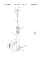
- FIG. 1 is an overall view of the lead extraction system containing an electrode means having a plurality of memory-shaped Nitinol sheet members at its distal tip section constructed in accordance with the principles of the present invention.
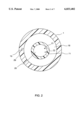
- FIG. 2 is a transverse view of the A--A section of FIG. 1 showing the plurality of lumens of the guiding shaft.
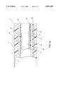
- FIG. 3A is a side view of the distal section of the guiding shaft of the lead extraction system of the present invention at a non-deployed state.
- FIG. 3B is a side view of the distal section of the guiding shaft of the lead extraction system of the present invention at a deployed state.
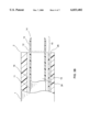
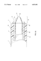
- FIG. 3C is a side view of the distal section of the guiding shaft of the lead extraction system of the present invention at a deployed state when the Nitinol sheet members are activated.
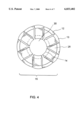
- FIG. 4 is a transverse view of the distal end of the inner catheter of the B--B section of FIG. 3C.
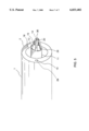
- FIG. 5 is a perspective view of the distal tip section of the lead extraction system of the present invention.
- FIG. 1 shows an overall view of the lead extraction system comprising a guiding shaft 1 having a shaft distal end 2, a shaft proximal end 3, and at least one lumen 18, 19 extending between the shaft distal end 2 and the shaft proximal end 3.
- a handle 4 is attached to the shaft proximal end 3 of the guiding shaft 1, wherein the handle 4 has a cavity 8.
- a retractable inner catheter 11 is located inside the at least one lumen 18 of the guiding shaft 1, wherein the retractable inner catheter 11 has a distal end 12 and a proximal end 5.
- An electrode means 15 having a plurality of sheet members 13 is secured to the distal end 12 of the retractable inner catheter 11.
- Each of the plurality sheet members 13 of the electrode means 15 has a proximal end and a sharp-edge distal end 14, wherein the proximal ends of the plurality sheet members 13 are joined at the distal end 12 of the retractable inner catheter 11.
- An electrical conductor 22 is attached to the electrode means 15.
- a deployment controller 6 is mounted on the handle 4 and is secured to the proximal end 5 of the retractable inner catheter 11.
- the deployment controller 6 has a deployed state for the retractable inner catheter 11 to deploy outside of the shaft distal end 2 of the guiding shaft 1 and the deployment controller 6 also has a non-deployed state for the retractable inner catheter 11 to be retracted within the at least one lumen of the guiding shaft 1.
- a connector means 7 for the conducting wire 22 to be used to transmit the RF current and for the temperature sensing wires 21 is located on the handle 4 of the lead extraction system.
- a fluid irrigation means 9 is located close to the proximal end of the handle 4.
- FIG. 2 shows a transverse view of the A--A section of FIG. 1, whereby it shows the at least one lumens 18, 19 of the guiding shaft 1.
- the lumen 19 is used for conveying fluid from the fluid irrigation means 9 to the fluid venting opening 29.
- the fluid is selected from the group consisting of saline, heparin, antibiotics, anti-inflammatory agent, chemotherapy fluid, therapeutics fluid and the like.
- An inner catheter 11 having at least one lumen 28 is located within the at least one lumen 18 of the guiding shaft 1.
- the electrical conductor 22 is connected to the electrode means 15 while the temperature sensing wires 21 are connected to the temperature sensor means 20 on the electrode means 15.
- FIG. 3A shows a side view of the distal section of the guiding shaft 1 of the lead extraction system of the present invention at a non-deployed state.
- the retractable inner catheter 11 along with the distal end 14 of the electrode means 15 stays within the lumen 18 of the guiding shaft 1.
- the plurality of sheet members 13 of the electrode means 15 has its original shape that is parallel to the axis of the guiding shaft 1.
- the retractable inner catheter 11 is deployed so that the electrode portion 15 is out of the distal end 2 of the guiding shaft 1.
- the sheet members 13 of the electrode means 15 have their original shape, which is parallel to the axis of the guiding shaft 1.
- FIG. 3C shows a side view of the distal section of the guiding shaft 1 of the lead extraction system of the present invention at a deployed state when the memory-shaped Nitinol sheet members 13 are activated.
- the deployed electrode means defines an ablation target of the scar tissue covering the implanted lead.
- the sharp-edge distal end 14 of the electrode means is positioned to directly face the target scar tissue.
- a RF current is applied to the electrode means 15 and the tissue temperature rises from the baseline body temperature of about 37° C. to about a transitional shape-change temperature for Nitinol sheet member, for example 50° C.
- the sheet members 13 of the electrode means 15 encounter said transitional temperature, the memory-shaped Nitinol sheet members 13 turn inwardly.
- Each of the Nitinol sheet members 13 is pre-shaped inwardly so that a circular enclosure 30 is formed by the distal ends 14 of all the sheet members.
- the diameter of the circular enclosure 30 is about the diameter of the lead to be extracted.
- the Nitinol sheet members 13 maintain this shape as long as the temperature is at or above the transitional temperature. After separating the scar tissue from the lead, the RF current is turned off and the temperature of the surrounding tissues drops to below the transitional temperature. The Nitinol sheet members 13 then return to their original shape at a temperature below the transitional temperature.
- the RF current is preferably within the range of 50 to 2,000 kHz.
- FIG. 4 shows a transverse view of the distal end 12 of the inner catheter of the B--B section of FIG. 3C.
- the enclosure 30 is about the same diameter of the lead to be extracted. Therefore, when RF current is applied, the sharp-edge distal ends 14 of the electrode means 15 cut into the attached scar tissue to loosen and separate it from the lead.
- FIG. 5 shows a perspective view of the distal tip section of the lead extraction system of the present invention.
- the Nitinol sheet members 13 of the electrode portion are conductive and can deliver RF energy when it contacts the tissue.
- the sharp edge 14 of the electrode 15 is used to cut through the scar tissue associated with the implanted lead. The cutting operation is achieved by a combination of advancing the electrode means, and/or heating the electrode means.
- the surfaces of the guiding shaft and the inner catheter are not conductive.
- the lead extraction system may further comprise a stylet locking mechanism at the handle for controlling the advancement and locking activities of the locking stylet of the guiding shaft.
- a stylet-locking plunger of the locking mechanism at the handle is used to control the degree of the advancement of the locking stylet of the guiding shaft.
- the stylet locking mechanism on the lead extraction system is well known to those who are skilled in the art.
- the lead extraction system further comprises a temperature sensing and closed-loop temperature controller for the electrode means 15 having a temperature sensor 20 close to the tissue contact site. Temperature sensing wires 21 along with a thermocouple or thermister means is provided to transmit the temperature data from the tissue contact site to an external temperature measuring and control apparatus. An algorithm is equipped for the ablation system so that a closed-loop temperature control is effective and the temperature data is relayed to an external RF generator for controlled energy delivery.
Abstract
Description
Claims (20)
Priority Applications (2)
| Application Number | Priority Date | Filing Date | Title |
|---|---|---|---|
| US09/161,890 US6033402A (en) | 1998-09-28 | 1998-09-28 | Ablation device for lead extraction and methods thereof |
| NZ507863A NZ507863A (en) | 1998-09-28 | 1999-09-27 | Door operator delays starting of motor for a time after actuation of flasher module light |
Applications Claiming Priority (1)
| Application Number | Priority Date | Filing Date | Title |
|---|---|---|---|
| US09/161,890 US6033402A (en) | 1998-09-28 | 1998-09-28 | Ablation device for lead extraction and methods thereof |
Publications (1)
| Publication Number | Publication Date |
|---|---|
| US6033402A true US6033402A (en) | 2000-03-07 |
Family
ID=22583222
Family Applications (1)
| Application Number | Title | Priority Date | Filing Date |
|---|---|---|---|
| US09/161,890 Expired - Lifetime US6033402A (en) | 1998-09-28 | 1998-09-28 | Ablation device for lead extraction and methods thereof |
Country Status (1)
| Country | Link |
|---|---|
| US (1) | US6033402A (en) |
Cited By (77)
| Publication number | Priority date | Publication date | Assignee | Title |
|---|---|---|---|---|
| US6241692B1 (en) * | 1998-10-06 | 2001-06-05 | Irvine Biomedical, Inc. | Ultrasonic ablation device and methods for lead extraction |
| US6277083B1 (en) | 1999-12-27 | 2001-08-21 | Neothermia Corporation | Minimally invasive intact recovery of tissue |
| US20020091382A1 (en) * | 2000-04-27 | 2002-07-11 | Hooven Michael D. | Transmural ablation device with curved jaws |
| US20020138109A1 (en) * | 2001-01-13 | 2002-09-26 | Medtronic, Inc. | Method and system for organ positioning and stabilization |
| US6471659B2 (en) | 1999-12-27 | 2002-10-29 | Neothermia Corporation | Minimally invasive intact recovery of tissue |
| US20030125729A1 (en) * | 2000-04-27 | 2003-07-03 | Hooven Michael D. | Transmural ablation device |
| US20040260280A1 (en) * | 2003-05-01 | 2004-12-23 | Sartor Joe Don | Suction coagulator with dissecting probe |
| US20050090818A1 (en) * | 2003-10-27 | 2005-04-28 | Pike Robert W.Jr. | Method for ablating with needle electrode |
| US20050177151A1 (en) * | 2001-06-20 | 2005-08-11 | Coen Thomas P. | Irrigation sheath |
| US20050192591A1 (en) * | 2004-02-27 | 2005-09-01 | Lui Chun K. | Device for removing an elongated structure implanted in biological tissue |
| US20050234444A1 (en) * | 2004-04-14 | 2005-10-20 | Hooven Michael D | Electrode and bipolar ablation method using same |
| US20060025838A1 (en) * | 1999-04-16 | 2006-02-02 | Laufer Michael D | Device for shaping infarcted heart tissue and method of using the device |
| US20060247572A1 (en) * | 2005-04-28 | 2006-11-02 | C. R. Bard, Inc. | Medical device removal system |
| US20070049863A1 (en) * | 2003-01-14 | 2007-03-01 | Jahns Scott E | Devices and methods for interstitial injection of biologic agents into tissue |
| US20070156209A1 (en) * | 2005-01-14 | 2007-07-05 | Co-Repair, Inc. | System for the treatment of heart tissue |
| US20070156210A1 (en) * | 2005-01-14 | 2007-07-05 | Co-Repair, Inc., A California Corporation | Method for the treatment of heart tissue |
| DE102006005224A1 (en) * | 2006-01-31 | 2007-08-09 | P + P Medical Gmbh | Device for separating an endoprosthesis from biological and / or biocompatible materials |
| US20080082099A1 (en) * | 2006-09-29 | 2008-04-03 | Duane Dickens | Surgical probe and methods for targeted treatment of heart structures |
| EP1909660A2 (en) * | 2005-07-27 | 2008-04-16 | The Spectranetics Corporation | Endocardial lead removing apparatus |
| US20080140071A1 (en) * | 2006-12-07 | 2008-06-12 | Cierra, Inc. | Electrode apparatus having at least one adjustment zone |
| US20090030413A1 (en) * | 2007-07-27 | 2009-01-29 | Gerut Zachary E | Surgical instrument and method for treating scar encapsulation |
| US20090163900A1 (en) * | 2004-09-17 | 2009-06-25 | Spectranetics | Rapid exchange bias laser catheter design |
| EP1935349A3 (en) * | 2006-12-22 | 2009-11-18 | The Spectranetics Corporation | Retractable separating systems |
| US20090287204A1 (en) * | 2005-01-14 | 2009-11-19 | Co-Repair, Inc. | System And Method For The Treatment Of Heart Tissue |
| US7678111B2 (en) | 1997-07-18 | 2010-03-16 | Medtronic, Inc. | Device and method for ablating tissue |
| US7740623B2 (en) | 2001-01-13 | 2010-06-22 | Medtronic, Inc. | Devices and methods for interstitial injection of biologic agents into tissue |
| US20100179424A1 (en) * | 2009-01-09 | 2010-07-15 | Reinhard Warnking | Methods and apparatus for treatment of mitral valve insufficiency |
| US20110009750A1 (en) * | 2004-09-17 | 2011-01-13 | Spectranetics | Cardiovascular imaging system |
| US7875028B2 (en) | 2004-06-02 | 2011-01-25 | Medtronic, Inc. | Ablation device with jaws |
| US20110106099A1 (en) * | 2009-10-29 | 2011-05-05 | Medtronic, Inc. | Lead extraction device |
| US7967816B2 (en) | 2002-01-25 | 2011-06-28 | Medtronic, Inc. | Fluid-assisted electrosurgical instrument with shapeable electrode |
| US20110208207A1 (en) * | 2005-07-27 | 2011-08-25 | Bowe Wade A | Endocardial lead removing apparatus |
| US8128636B2 (en) | 2006-02-13 | 2012-03-06 | Cook Medical Technologies Llc | Device and method for removing lumenless leads |
| US8328798B2 (en) | 1999-10-02 | 2012-12-11 | Quantumcor, Inc | Method for treating and repairing mitral valve annulus |
| EP2589348A1 (en) * | 2011-11-03 | 2013-05-08 | VascoMed GmbH | Device for explanting electrode leads |
| EP2789314A2 (en) | 2003-10-06 | 2014-10-15 | 3F Therapeutics, Inc | Minimally invasive valve replacement system |
| US8961551B2 (en) | 2006-12-22 | 2015-02-24 | The Spectranetics Corporation | Retractable separating systems and methods |
| WO2015028882A1 (en) * | 2013-08-25 | 2015-03-05 | Talpanetics bv | Extractor for removing a lead from a patient |
| US9028520B2 (en) | 2006-12-22 | 2015-05-12 | The Spectranetics Corporation | Tissue separating systems and methods |
| US20150223754A1 (en) * | 2008-02-25 | 2015-08-13 | Atrial Systems, Llc | Force assessment device and method for lead extraction |
| US9283040B2 (en) | 2013-03-13 | 2016-03-15 | The Spectranetics Corporation | Device and method of ablative cutting with helical tip |
| US9291663B2 (en) | 2013-03-13 | 2016-03-22 | The Spectranetics Corporation | Alarm for lead insulation abnormality |
| US9413896B2 (en) | 2012-09-14 | 2016-08-09 | The Spectranetics Corporation | Tissue slitting methods and systems |
| USD765243S1 (en) | 2015-02-20 | 2016-08-30 | The Spectranetics Corporation | Medical device handle |
| US9456872B2 (en) | 2013-03-13 | 2016-10-04 | The Spectranetics Corporation | Laser ablation catheter |
| USD770616S1 (en) | 2015-02-20 | 2016-11-01 | The Spectranetics Corporation | Medical device handle |
| US9603618B2 (en) | 2013-03-15 | 2017-03-28 | The Spectranetics Corporation | Medical device for removing an implanted object |
| US9622762B2 (en) | 2013-09-18 | 2017-04-18 | Xablecath Inc. | Catheter devices for crossing and treating an occlusion |
| US9623211B2 (en) | 2013-03-13 | 2017-04-18 | The Spectranetics Corporation | Catheter movement control |
| US20170105762A1 (en) * | 2015-10-15 | 2017-04-20 | Medtronic Advanced Energy Llc | Lead extraction |
| US20170112501A1 (en) * | 2014-03-21 | 2017-04-27 | The United States of America, as represented by the Secretary, Department of Health & Human Servic | Conductive and retrievable devices |
| US9668765B2 (en) | 2013-03-15 | 2017-06-06 | The Spectranetics Corporation | Retractable blade for lead removal device |
| US9700372B2 (en) | 2002-07-01 | 2017-07-11 | Recor Medical, Inc. | Intraluminal methods of ablating nerve tissue |
| US9757200B2 (en) | 2013-03-14 | 2017-09-12 | The Spectranetics Corporation | Intelligent catheter |
| WO2017180465A1 (en) * | 2016-04-15 | 2017-10-19 | University Of Floriada Research Foundation, Inc. | Removing electrical leads attached to the body by natural tissue growth |
| US9883885B2 (en) | 2013-03-13 | 2018-02-06 | The Spectranetics Corporation | System and method of ablative cutting and pulsed vacuum aspiration |
| US9925366B2 (en) | 2013-03-15 | 2018-03-27 | The Spectranetics Corporation | Surgical instrument for removing an implanted object |
| US9980743B2 (en) | 2013-03-15 | 2018-05-29 | The Spectranetics Corporation | Medical device for removing an implanted object using laser cut hypotubes |
| US10136913B2 (en) | 2013-03-15 | 2018-11-27 | The Spectranetics Corporation | Multiple configuration surgical cutting device |
| US10207105B2 (en) | 2013-08-25 | 2019-02-19 | Talpanetics bv | Extractor for removing a lead from a patient |
| US10258792B2 (en) | 2005-07-22 | 2019-04-16 | The Spectranetics Corporation | Endocardial lead cutting apparatus |
| US10383691B2 (en) | 2013-03-13 | 2019-08-20 | The Spectranetics Corporation | Last catheter with helical internal lumen |
| US20190262580A1 (en) * | 2008-06-20 | 2019-08-29 | Angiodynamics, Inc. | Device and Method for the Ablation of Fibrin Sheath Formation on a Venous Catheter |
| US10405924B2 (en) | 2014-05-30 | 2019-09-10 | The Spectranetics Corporation | System and method of ablative cutting and vacuum aspiration through primary orifice and auxiliary side port |
| US10448999B2 (en) | 2013-03-15 | 2019-10-22 | The Spectranetics Corporation | Surgical instrument for removing an implanted object |
| US10646274B2 (en) | 2014-12-30 | 2020-05-12 | Regents Of The University Of Minnesota | Laser catheter with use of reflected light and force indication to determine material type in vascular system |
| US10646275B2 (en) | 2014-12-30 | 2020-05-12 | Regents Of The University Of Minnesota | Laser catheter with use of determined material type in vascular system in ablation of material |
| US10646118B2 (en) | 2014-12-30 | 2020-05-12 | Regents Of The University Of Minnesota | Laser catheter with use of reflected light to determine material type in vascular system |
| US10758308B2 (en) | 2013-03-14 | 2020-09-01 | The Spectranetics Corporation | Controller to select optical channel parameters in a catheter |
| US10835279B2 (en) | 2013-03-14 | 2020-11-17 | Spectranetics Llc | Distal end supported tissue slitting apparatus |
| US10842532B2 (en) | 2013-03-15 | 2020-11-24 | Spectranetics Llc | Medical device for removing an implanted object |
| US10952785B2 (en) | 2016-08-01 | 2021-03-23 | Medtronic Advanced Energy, Llc | Device for medical lead extraction |
| US10987168B2 (en) | 2014-05-29 | 2021-04-27 | Spectranetics Llc | System and method for coordinated laser delivery and imaging |
| EP3821852A2 (en) | 2003-10-06 | 2021-05-19 | Medtronic 3F Therapeutics, Inc. | Minimally invasive valve replacement system |
| US11642169B2 (en) | 2013-03-14 | 2023-05-09 | The Spectranetics Corporation | Smart multiplexed medical laser system |
| US11883089B2 (en) | 2016-11-14 | 2024-01-30 | Medtronic, Inc. | Controlled optical properties vitreous enamel composition for electrosurgical tool |
| US11931096B2 (en) | 2010-10-13 | 2024-03-19 | Angiodynamics, Inc. | System and method for electrically ablating tissue of a patient |
Citations (5)
| Publication number | Priority date | Publication date | Assignee | Title |
|---|---|---|---|---|
| US5423806A (en) * | 1993-10-01 | 1995-06-13 | Medtronic, Inc. | Laser extractor for an implanted object |
| US5620451A (en) * | 1995-04-25 | 1997-04-15 | Intermedics, Inc. | Lead extraction system for transvenous defibrillation leads and for endocardial pacing leads |
| US5697936A (en) * | 1988-11-10 | 1997-12-16 | Cook Pacemaker Corporation | Device for removing an elongated structure implanted in biological tissue |
| US5779715A (en) * | 1997-07-28 | 1998-07-14 | Irvine Biomedical, Inc. | Lead extraction system and methods thereof |
| US5980515A (en) * | 1997-12-19 | 1999-11-09 | Irvine Biomedical, Inc. | Devices and methods for lead extraction |
-
1998
- 1998-09-28 US US09/161,890 patent/US6033402A/en not_active Expired - Lifetime
Patent Citations (6)
| Publication number | Priority date | Publication date | Assignee | Title |
|---|---|---|---|---|
| US5697936A (en) * | 1988-11-10 | 1997-12-16 | Cook Pacemaker Corporation | Device for removing an elongated structure implanted in biological tissue |
| US5423806A (en) * | 1993-10-01 | 1995-06-13 | Medtronic, Inc. | Laser extractor for an implanted object |
| US5674217A (en) * | 1993-10-01 | 1997-10-07 | Wahlstrom; Dale A. | Heart synchronized extractor for an implanted object |
| US5620451A (en) * | 1995-04-25 | 1997-04-15 | Intermedics, Inc. | Lead extraction system for transvenous defibrillation leads and for endocardial pacing leads |
| US5779715A (en) * | 1997-07-28 | 1998-07-14 | Irvine Biomedical, Inc. | Lead extraction system and methods thereof |
| US5980515A (en) * | 1997-12-19 | 1999-11-09 | Irvine Biomedical, Inc. | Devices and methods for lead extraction |
Cited By (146)
| Publication number | Priority date | Publication date | Assignee | Title |
|---|---|---|---|---|
| US7678111B2 (en) | 1997-07-18 | 2010-03-16 | Medtronic, Inc. | Device and method for ablating tissue |
| US6241692B1 (en) * | 1998-10-06 | 2001-06-05 | Irvine Biomedical, Inc. | Ultrasonic ablation device and methods for lead extraction |
| US20060025838A1 (en) * | 1999-04-16 | 2006-02-02 | Laufer Michael D | Device for shaping infarcted heart tissue and method of using the device |
| US8285393B2 (en) | 1999-04-16 | 2012-10-09 | Laufer Michael D | Device for shaping infarcted heart tissue and method of using the device |
| US8328798B2 (en) | 1999-10-02 | 2012-12-11 | Quantumcor, Inc | Method for treating and repairing mitral valve annulus |
| US6277083B1 (en) | 1999-12-27 | 2001-08-21 | Neothermia Corporation | Minimally invasive intact recovery of tissue |
| US6471659B2 (en) | 1999-12-27 | 2002-10-29 | Neothermia Corporation | Minimally invasive intact recovery of tissue |
| US20050021024A1 (en) * | 2000-04-27 | 2005-01-27 | Hooven Michael D. | Transmural ablation device with temperature sensor |
| US20070135811A1 (en) * | 2000-04-27 | 2007-06-14 | Hooven Michael D | Method for ablating cardiac tissue |
| US20050033282A1 (en) * | 2000-04-27 | 2005-02-10 | Hooven Michael D. | Transmural ablation device with parallel electrodes |
| US20030125729A1 (en) * | 2000-04-27 | 2003-07-03 | Hooven Michael D. | Transmural ablation device |
| US20050171530A1 (en) * | 2000-04-27 | 2005-08-04 | Hooven Michael D. | Transmural ablation device |
| US20020115993A1 (en) * | 2000-04-27 | 2002-08-22 | Hooven Michael D. | Transmural ablation device with gold-plated copper electrodes |
| US20020091382A1 (en) * | 2000-04-27 | 2002-07-11 | Hooven Michael D. | Transmural ablation device with curved jaws |
| US20020138109A1 (en) * | 2001-01-13 | 2002-09-26 | Medtronic, Inc. | Method and system for organ positioning and stabilization |
| US7740623B2 (en) | 2001-01-13 | 2010-06-22 | Medtronic, Inc. | Devices and methods for interstitial injection of biologic agents into tissue |
| US20050177151A1 (en) * | 2001-06-20 | 2005-08-11 | Coen Thomas P. | Irrigation sheath |
| US7967816B2 (en) | 2002-01-25 | 2011-06-28 | Medtronic, Inc. | Fluid-assisted electrosurgical instrument with shapeable electrode |
| US9707034B2 (en) | 2002-07-01 | 2017-07-18 | Recor Medical, Inc. | Intraluminal method and apparatus for ablating nerve tissue |
| US9700372B2 (en) | 2002-07-01 | 2017-07-11 | Recor Medical, Inc. | Intraluminal methods of ablating nerve tissue |
| US20070049863A1 (en) * | 2003-01-14 | 2007-03-01 | Jahns Scott E | Devices and methods for interstitial injection of biologic agents into tissue |
| US7744562B2 (en) | 2003-01-14 | 2010-06-29 | Medtronics, Inc. | Devices and methods for interstitial injection of biologic agents into tissue |
| US8273072B2 (en) | 2003-01-14 | 2012-09-25 | Medtronic, Inc. | Devices and methods for interstitial injection of biologic agents into tissue |
| US20040260280A1 (en) * | 2003-05-01 | 2004-12-23 | Sartor Joe Don | Suction coagulator with dissecting probe |
| EP3821852A2 (en) | 2003-10-06 | 2021-05-19 | Medtronic 3F Therapeutics, Inc. | Minimally invasive valve replacement system |
| EP2789314A2 (en) | 2003-10-06 | 2014-10-15 | 3F Therapeutics, Inc | Minimally invasive valve replacement system |
| US20050090818A1 (en) * | 2003-10-27 | 2005-04-28 | Pike Robert W.Jr. | Method for ablating with needle electrode |
| US7207989B2 (en) * | 2003-10-27 | 2007-04-24 | Biosense Webster, Inc. | Method for ablating with needle electrode |
| US20090069808A1 (en) * | 2003-10-27 | 2009-03-12 | Pike Jr Robert W | Method for ablating with needle electrode |
| US9326813B2 (en) * | 2003-10-27 | 2016-05-03 | Biosense Webster, Inc. | Method for ablating with needle electrode |
| US20050192591A1 (en) * | 2004-02-27 | 2005-09-01 | Lui Chun K. | Device for removing an elongated structure implanted in biological tissue |
| US20050234444A1 (en) * | 2004-04-14 | 2005-10-20 | Hooven Michael D | Electrode and bipolar ablation method using same |
| US8162941B2 (en) | 2004-06-02 | 2012-04-24 | Medtronic, Inc. | Ablation device with jaws |
| US7875028B2 (en) | 2004-06-02 | 2011-01-25 | Medtronic, Inc. | Ablation device with jaws |
| US8628519B2 (en) | 2004-09-17 | 2014-01-14 | The Spectranetics Corporation | Rapid exchange bias laser catheter design |
| US10111709B2 (en) | 2004-09-17 | 2018-10-30 | The Spectranetics Corporation | Rapid exchange bias laser catheter design |
| US10959699B2 (en) | 2004-09-17 | 2021-03-30 | The Spectranetics Corporation | Cardiovascular imaging system |
| US20110009750A1 (en) * | 2004-09-17 | 2011-01-13 | Spectranetics | Cardiovascular imaging system |
| US8545488B2 (en) | 2004-09-17 | 2013-10-01 | The Spectranetics Corporation | Cardiovascular imaging system |
| US9308047B2 (en) | 2004-09-17 | 2016-04-12 | The Spectranetics Corporation | Rapid exchange bias laser catheter design |
| US20090163900A1 (en) * | 2004-09-17 | 2009-06-25 | Spectranetics | Rapid exchange bias laser catheter design |
| US20070156210A1 (en) * | 2005-01-14 | 2007-07-05 | Co-Repair, Inc., A California Corporation | Method for the treatment of heart tissue |
| US20070156209A1 (en) * | 2005-01-14 | 2007-07-05 | Co-Repair, Inc. | System for the treatment of heart tissue |
| US20090287204A1 (en) * | 2005-01-14 | 2009-11-19 | Co-Repair, Inc. | System And Method For The Treatment Of Heart Tissue |
| US20060247572A1 (en) * | 2005-04-28 | 2006-11-02 | C. R. Bard, Inc. | Medical device removal system |
| US8025668B2 (en) * | 2005-04-28 | 2011-09-27 | C. R. Bard, Inc. | Medical device removal system |
| US8287551B2 (en) * | 2005-04-28 | 2012-10-16 | C. R. Bard, Inc. | Medical device removal system |
| US10258792B2 (en) | 2005-07-22 | 2019-04-16 | The Spectranetics Corporation | Endocardial lead cutting apparatus |
| US20110208207A1 (en) * | 2005-07-27 | 2011-08-25 | Bowe Wade A | Endocardial lead removing apparatus |
| EP1909660A4 (en) * | 2005-07-27 | 2013-04-17 | Spectranetics Corp | Endocardial lead removing apparatus |
| EP1909660A2 (en) * | 2005-07-27 | 2008-04-16 | The Spectranetics Corporation | Endocardial lead removing apparatus |
| US8097012B2 (en) | 2005-07-27 | 2012-01-17 | The Spectranetics Corporation | Endocardial lead removing apparatus |
| DE102006005224A1 (en) * | 2006-01-31 | 2007-08-09 | P + P Medical Gmbh | Device for separating an endoprosthesis from biological and / or biocompatible materials |
| US20100063499A1 (en) * | 2006-01-31 | 2010-03-11 | Andreas Pein | Device for Removing an Endoprosthesis or an Implant that is Implanted in the Body and is Made of a Synthetic Material |
| DE102006005224B4 (en) * | 2006-01-31 | 2008-09-04 | P + P Medical Gmbh | Device for separating an existing from an electrically conductive material Gelenkendoprothese of biological and / or biocompatible materials |
| US8128636B2 (en) | 2006-02-13 | 2012-03-06 | Cook Medical Technologies Llc | Device and method for removing lumenless leads |
| US8187266B2 (en) | 2006-09-29 | 2012-05-29 | Quantumcor, Inc. | Surgical probe and methods for targeted treatment of heart structures |
| US20080082099A1 (en) * | 2006-09-29 | 2008-04-03 | Duane Dickens | Surgical probe and methods for targeted treatment of heart structures |
| US20080140071A1 (en) * | 2006-12-07 | 2008-06-12 | Cierra, Inc. | Electrode apparatus having at least one adjustment zone |
| EP1935349A3 (en) * | 2006-12-22 | 2009-11-18 | The Spectranetics Corporation | Retractable separating systems |
| US10869687B2 (en) | 2006-12-22 | 2020-12-22 | Spectranetics Llc | Tissue separating systems and methods |
| US9808275B2 (en) | 2006-12-22 | 2017-11-07 | The Spectranetics Corporation | Retractable separating systems and methods |
| US9028520B2 (en) | 2006-12-22 | 2015-05-12 | The Spectranetics Corporation | Tissue separating systems and methods |
| US9289226B2 (en) | 2006-12-22 | 2016-03-22 | The Spectranetics Corporation | Retractable separating systems and methods |
| US10537354B2 (en) | 2006-12-22 | 2020-01-21 | The Spectranetics Corporation | Retractable separating systems and methods |
| US8961551B2 (en) | 2006-12-22 | 2015-02-24 | The Spectranetics Corporation | Retractable separating systems and methods |
| US9801650B2 (en) | 2006-12-22 | 2017-10-31 | The Spectranetics Corporation | Tissue separating systems and methods |
| US20090030413A1 (en) * | 2007-07-27 | 2009-01-29 | Gerut Zachary E | Surgical instrument and method for treating scar encapsulation |
| US9839393B2 (en) | 2008-02-25 | 2017-12-12 | Atrial Systems, Llc | Force assessment device and method for lead extraction |
| US9414783B2 (en) * | 2008-02-25 | 2016-08-16 | Atrial Systems, Llc | Force assessment device and method for lead extraction |
| US20150223754A1 (en) * | 2008-02-25 | 2015-08-13 | Atrial Systems, Llc | Force assessment device and method for lead extraction |
| US20190262580A1 (en) * | 2008-06-20 | 2019-08-29 | Angiodynamics, Inc. | Device and Method for the Ablation of Fibrin Sheath Formation on a Venous Catheter |
| US8974445B2 (en) | 2009-01-09 | 2015-03-10 | Recor Medical, Inc. | Methods and apparatus for treatment of cardiac valve insufficiency |
| US20100179424A1 (en) * | 2009-01-09 | 2010-07-15 | Reinhard Warnking | Methods and apparatus for treatment of mitral valve insufficiency |
| US20110106099A1 (en) * | 2009-10-29 | 2011-05-05 | Medtronic, Inc. | Lead extraction device |
| US11931096B2 (en) | 2010-10-13 | 2024-03-19 | Angiodynamics, Inc. | System and method for electrically ablating tissue of a patient |
| EP2589348A1 (en) * | 2011-11-03 | 2013-05-08 | VascoMed GmbH | Device for explanting electrode leads |
| US9339269B2 (en) | 2011-11-03 | 2016-05-17 | Vascomed Gmbh | Device for explanting electrode leads |
| US10368900B2 (en) | 2012-09-14 | 2019-08-06 | The Spectranetics Corporation | Tissue slitting methods and systems |
| US9949753B2 (en) | 2012-09-14 | 2018-04-24 | The Spectranetics Corporation | Tissue slitting methods and systems |
| US10531891B2 (en) | 2012-09-14 | 2020-01-14 | The Spectranetics Corporation | Tissue slitting methods and systems |
| US9413896B2 (en) | 2012-09-14 | 2016-08-09 | The Spectranetics Corporation | Tissue slitting methods and systems |
| US9724122B2 (en) | 2012-09-14 | 2017-08-08 | The Spectranetics Corporation | Expandable lead jacket |
| US9763692B2 (en) | 2012-09-14 | 2017-09-19 | The Spectranetics Corporation | Tissue slitting methods and systems |
| US11596435B2 (en) | 2012-09-14 | 2023-03-07 | Specrtranetics Llc | Tissue slitting methods and systems |
| US10265520B2 (en) | 2013-03-13 | 2019-04-23 | The Spetranetics Corporation | Alarm for lead insulation abnormality |
| US10799293B2 (en) | 2013-03-13 | 2020-10-13 | The Spectranetics Corporation | Laser ablation catheter |
| US9623211B2 (en) | 2013-03-13 | 2017-04-18 | The Spectranetics Corporation | Catheter movement control |
| US9827055B2 (en) | 2013-03-13 | 2017-11-28 | The Spectranetics Corporation | Catheter movement control |
| US10383691B2 (en) | 2013-03-13 | 2019-08-20 | The Spectranetics Corporation | Last catheter with helical internal lumen |
| US10485613B2 (en) | 2013-03-13 | 2019-11-26 | The Spectranetics Corporation | Device and method of ablative cutting with helical tip |
| US9883885B2 (en) | 2013-03-13 | 2018-02-06 | The Spectranetics Corporation | System and method of ablative cutting and pulsed vacuum aspiration |
| US9283040B2 (en) | 2013-03-13 | 2016-03-15 | The Spectranetics Corporation | Device and method of ablative cutting with helical tip |
| US9291663B2 (en) | 2013-03-13 | 2016-03-22 | The Spectranetics Corporation | Alarm for lead insulation abnormality |
| US9456872B2 (en) | 2013-03-13 | 2016-10-04 | The Spectranetics Corporation | Laser ablation catheter |
| US9925371B2 (en) | 2013-03-13 | 2018-03-27 | The Spectranetics Corporation | Alarm for lead insulation abnormality |
| US9937005B2 (en) | 2013-03-13 | 2018-04-10 | The Spectranetics Corporation | Device and method of ablative cutting with helical tip |
| US10206745B2 (en) | 2013-03-13 | 2019-02-19 | The Spectranetics Corporation | Catheter movement control |
| US10835279B2 (en) | 2013-03-14 | 2020-11-17 | Spectranetics Llc | Distal end supported tissue slitting apparatus |
| US10758308B2 (en) | 2013-03-14 | 2020-09-01 | The Spectranetics Corporation | Controller to select optical channel parameters in a catheter |
| US11642169B2 (en) | 2013-03-14 | 2023-05-09 | The Spectranetics Corporation | Smart multiplexed medical laser system |
| US9757200B2 (en) | 2013-03-14 | 2017-09-12 | The Spectranetics Corporation | Intelligent catheter |
| US10092363B2 (en) | 2013-03-14 | 2018-10-09 | The Spectranetics Corporation | Intelligent catheter |
| US11925380B2 (en) | 2013-03-14 | 2024-03-12 | Spectranetics Llc | Distal end supported tissue slitting apparatus |
| US10842532B2 (en) | 2013-03-15 | 2020-11-24 | Spectranetics Llc | Medical device for removing an implanted object |
| US10448999B2 (en) | 2013-03-15 | 2019-10-22 | The Spectranetics Corporation | Surgical instrument for removing an implanted object |
| US9925366B2 (en) | 2013-03-15 | 2018-03-27 | The Spectranetics Corporation | Surgical instrument for removing an implanted object |
| US10219819B2 (en) | 2013-03-15 | 2019-03-05 | The Spectranetics Corporation | Retractable blade for lead removal device |
| US9668765B2 (en) | 2013-03-15 | 2017-06-06 | The Spectranetics Corporation | Retractable blade for lead removal device |
| US9956399B2 (en) | 2013-03-15 | 2018-05-01 | The Spectranetics Corporation | Medical device for removing an implanted object |
| US9980743B2 (en) | 2013-03-15 | 2018-05-29 | The Spectranetics Corporation | Medical device for removing an implanted object using laser cut hypotubes |
| US10314615B2 (en) | 2013-03-15 | 2019-06-11 | The Spectranetics Corporation | Medical device for removing an implanted object |
| US11925334B2 (en) | 2013-03-15 | 2024-03-12 | Spectranetics Llc | Surgical instrument for removing an implanted object |
| US10136913B2 (en) | 2013-03-15 | 2018-11-27 | The Spectranetics Corporation | Multiple configuration surgical cutting device |
| US10052129B2 (en) | 2013-03-15 | 2018-08-21 | The Spectranetics Corporation | Medical device for removing an implanted object |
| US9918737B2 (en) | 2013-03-15 | 2018-03-20 | The Spectranetics Corporation | Medical device for removing an implanted object |
| US11160579B2 (en) | 2013-03-15 | 2021-11-02 | Spectranetics Llc | Multiple configuration surgical cutting device |
| US10849603B2 (en) | 2013-03-15 | 2020-12-01 | Spectranetics Llc | Surgical instrument for removing an implanted object |
| US9603618B2 (en) | 2013-03-15 | 2017-03-28 | The Spectranetics Corporation | Medical device for removing an implanted object |
| US10524817B2 (en) | 2013-03-15 | 2020-01-07 | The Spectranetics Corporation | Surgical instrument including an inwardly deflecting cutting tip for removing an implanted object |
| US9889294B2 (en) | 2013-08-25 | 2018-02-13 | Talpanetics bv | Extractor for removing a lead from a patient |
| US10532207B2 (en) | 2013-08-25 | 2020-01-14 | Talpanetics bv | Extractor for removing a lead from a patient |
| US11452868B2 (en) | 2013-08-25 | 2022-09-27 | Talpanetics bv | Extractor for removing a lead from a patient |
| US11648396B2 (en) | 2013-08-25 | 2023-05-16 | Talpanetics bv | Extractor for removing a lead from a patient |
| WO2015028882A1 (en) * | 2013-08-25 | 2015-03-05 | Talpanetics bv | Extractor for removing a lead from a patient |
| US10207105B2 (en) | 2013-08-25 | 2019-02-19 | Talpanetics bv | Extractor for removing a lead from a patient |
| US10499934B2 (en) | 2013-09-18 | 2019-12-10 | Xablecath Inc. | Methods for crossing and treating an occlusion |
| US9622762B2 (en) | 2013-09-18 | 2017-04-18 | Xablecath Inc. | Catheter devices for crossing and treating an occlusion |
| US10278715B2 (en) | 2013-09-18 | 2019-05-07 | Xablecath Inc. | Systems for use in crossing and treating an occlusion |
| US9826995B2 (en) | 2013-09-18 | 2017-11-28 | XableCath, Inc. | Support catheters for use in crossing and treating an occlusion |
| US20170112501A1 (en) * | 2014-03-21 | 2017-04-27 | The United States of America, as represented by the Secretary, Department of Health & Human Servic | Conductive and retrievable devices |
| US10987168B2 (en) | 2014-05-29 | 2021-04-27 | Spectranetics Llc | System and method for coordinated laser delivery and imaging |
| US10405924B2 (en) | 2014-05-30 | 2019-09-10 | The Spectranetics Corporation | System and method of ablative cutting and vacuum aspiration through primary orifice and auxiliary side port |
| US10646118B2 (en) | 2014-12-30 | 2020-05-12 | Regents Of The University Of Minnesota | Laser catheter with use of reflected light to determine material type in vascular system |
| US10646275B2 (en) | 2014-12-30 | 2020-05-12 | Regents Of The University Of Minnesota | Laser catheter with use of determined material type in vascular system in ablation of material |
| US10646274B2 (en) | 2014-12-30 | 2020-05-12 | Regents Of The University Of Minnesota | Laser catheter with use of reflected light and force indication to determine material type in vascular system |
| USD765243S1 (en) | 2015-02-20 | 2016-08-30 | The Spectranetics Corporation | Medical device handle |
| USD770616S1 (en) | 2015-02-20 | 2016-11-01 | The Spectranetics Corporation | Medical device handle |
| USD819204S1 (en) | 2015-02-20 | 2018-05-29 | The Spectranetics Corporation | Medical device handle |
| USD806245S1 (en) | 2015-02-20 | 2017-12-26 | The Spectranetics Corporation | Medical device handle |
| USD854682S1 (en) | 2015-02-20 | 2019-07-23 | The Spectranetics Corporation | Medical device handle |
| US20170105762A1 (en) * | 2015-10-15 | 2017-04-20 | Medtronic Advanced Energy Llc | Lead extraction |
| WO2017066615A1 (en) * | 2015-10-15 | 2017-04-20 | Medtronic Advanced Energy Llc. | Lead extraction |
| WO2017180465A1 (en) * | 2016-04-15 | 2017-10-19 | University Of Floriada Research Foundation, Inc. | Removing electrical leads attached to the body by natural tissue growth |
| US10952785B2 (en) | 2016-08-01 | 2021-03-23 | Medtronic Advanced Energy, Llc | Device for medical lead extraction |
| US11883089B2 (en) | 2016-11-14 | 2024-01-30 | Medtronic, Inc. | Controlled optical properties vitreous enamel composition for electrosurgical tool |
Similar Documents
| Publication | Publication Date | Title |
|---|---|---|
| US6033402A (en) | Ablation device for lead extraction and methods thereof | |
| US5980515A (en) | Devices and methods for lead extraction | |
| US5779715A (en) | Lead extraction system and methods thereof | |
| US6241692B1 (en) | Ultrasonic ablation device and methods for lead extraction | |
| US5782828A (en) | Ablation catheter with multiple flexible curves | |
| US5891138A (en) | Catheter system having parallel electrodes | |
| US6231570B1 (en) | Electrode catheter system for tissue ablation | |
| US6241726B1 (en) | Catheter system having a tip section with fixation means | |
| EP3436138B1 (en) | Chronically implantable medical devices configured for extraction and extraction devices for extracting chronically implanted medical devices | |
| US5897554A (en) | Steerable catheter having a loop electrode | |
| US6217576B1 (en) | Catheter probe for treating focal atrial fibrillation in pulmonary veins | |
| US5891137A (en) | Catheter system having a tip with fixation means | |
| US6190382B1 (en) | Radio-frequency based catheter system for ablation of body tissues | |
| US6156033A (en) | Ablation catheter having electrode means and methods thereof | |
| US6178354B1 (en) | Internal mechanism for displacing a slidable electrode | |
| US6972016B2 (en) | Helically shaped electrophysiology catheter | |
| EP1595576B1 (en) | Non-contact tissue ablation device | |
| US6290697B1 (en) | Self-guiding catheter system for tissue ablation | |
| US5843152A (en) | Catheter system having a ball electrode | |
| US5882346A (en) | Shapable catheter using exchangeable core and method of use | |
| US5083565A (en) | Electrosurgical instrument for ablating endocardial tissue | |
| JP4125489B2 (en) | Electrophysiology catheter | |
| US5522873A (en) | Catheter having electrode with annular recess and method of using same | |
| US6029091A (en) | Catheter system having lattice electrodes | |
| JP2001521774A (en) | Ring-shaped electrode structure for diagnostic and ablation catheters |
Legal Events
| Date | Code | Title | Description |
|---|---|---|---|
| AS | Assignment |
Owner name: IRVINE BIOMEDICAL, INC., CALIFORNIA Free format text: ASSIGNMENT OF ASSIGNORS INTEREST;ASSIGNORS:TU, HOSHENG;HATA, CARY;REEL/FRAME:009494/0768 Effective date: 19980928 |
|
| STCF | Information on status: patent grant |
Free format text: PATENTED CASE |
|
| AS | Assignment |
Owner name: SILICON VALLEY BANK, CALIFORNIA Free format text: SECURITY INTEREST;ASSIGNOR:IRVINE BIOMEDICAL, INC.;REEL/FRAME:013625/0352 Effective date: 20021112 |
|
| FPAY | Fee payment |
Year of fee payment: 4 |
|
| AS | Assignment |
Owner name: IRVINE BIOMEDICAL, INC., CALIFORNIA Free format text: RELEASE BY SECURED PARTY;ASSIGNOR:SILICON VALLEY BANK;REEL/FRAME:015886/0107 Effective date: 20041007 |
|
| FEPP | Fee payment procedure |
Free format text: PAT HOLDER NO LONGER CLAIMS SMALL ENTITY STATUS, ENTITY STATUS SET TO UNDISCOUNTED (ORIGINAL EVENT CODE: STOL); ENTITY STATUS OF PATENT OWNER: LARGE ENTITY |
|
| FPAY | Fee payment |
Year of fee payment: 8 |
|
| FPAY | Fee payment |
Year of fee payment: 12 |