US6033293A - Apparatus for performing chemical-mechanical polishing - Google Patents
Apparatus for performing chemical-mechanical polishing Download PDFInfo
- Publication number
- US6033293A US6033293A US08/947,178 US94717897A US6033293A US 6033293 A US6033293 A US 6033293A US 94717897 A US94717897 A US 94717897A US 6033293 A US6033293 A US 6033293A
- Authority
- US
- United States
- Prior art keywords
- platen
- pad
- vacuum
- polishing
- substrate
- Prior art date
- Legal status (The legal status is an assumption and is not a legal conclusion. Google has not performed a legal analysis and makes no representation as to the accuracy of the status listed.)
- Expired - Fee Related
Links
Images
Classifications
-
- B—PERFORMING OPERATIONS; TRANSPORTING
- B24—GRINDING; POLISHING
- B24B—MACHINES, DEVICES, OR PROCESSES FOR GRINDING OR POLISHING; DRESSING OR CONDITIONING OF ABRADING SURFACES; FEEDING OF GRINDING, POLISHING, OR LAPPING AGENTS
- B24B37/00—Lapping machines or devices; Accessories
- B24B37/11—Lapping tools
-
- B—PERFORMING OPERATIONS; TRANSPORTING
- B24—GRINDING; POLISHING
- B24B—MACHINES, DEVICES, OR PROCESSES FOR GRINDING OR POLISHING; DRESSING OR CONDITIONING OF ABRADING SURFACES; FEEDING OF GRINDING, POLISHING, OR LAPPING AGENTS
- B24B45/00—Means for securing grinding wheels on rotary arbors
Definitions
- the present invention relates to an apparatus and method for performing chemical-mechanical polishing and, more particularly, to an apparatus and method for chemical-mechanical polishing involving a polishing pad and a platen secured together by a releasable attractive force.
- This invention has particular application to chemical-mechanical polishing for use in planarizing dielectrics.
- Chemical-mechanical polishing generally involves pressing a substrate against a wetted, polishing platen within a polisher apparatus, with the conditions being controlled as to the temperature, pressure, and chemical environment.
- CMP chemical-mechanical polishing
- a pad is glued onto a circular metal platen in the polisher.
- the CMP pad is usually about twenty to thirty inches in diameter and 100 mils in thickness, depending on the application.
- the pads are customarily formed of a relatively soft material, such as polyurethane.
- the substrate to be planarized is placed on a carrier and then pressed against the pad while both the pad and substrate rotate, as a polishing slurry is applied.
- the polishing slurry often is comprised of abrasive materials (i.e., silica, alumina, or ceria), suspended in water, with additives to obtain a specific pH and create oxide layers on the materials to be polished that can be abraded easily by the particles.
- abrasive materials i.e., silica, alumina, or ceria
- the friction between the substrate and the pad can generate a significant amount of heat.
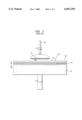
- FIG. 1 illustrates a pad and platen as used in a typical CMP polisher apparatus.
- a CMP apparatus comprises a pad 10 and a platen 12; a layer of adhesive 14 secures the pad to the platen when they are pressed together following the arrows A.
- the substrate 16 to be planarized is secured to a carrier 18.
- the carrier 18 may include a vacuum (not shown) for holding the substrate to the carrier during the load and unload steps. While polishing, however, the vacuum is normally deactivated, and the substrate 16 is held in place by the high coefficient of friction between the carrier 18 and the substrate 16.
- the carrier may be conformed (e.g., with use of a polymer sheet or wax) to receive the substrate 16, and it may be adapted to receive a plurality of substrates to be planarized simultaneously.
- a polishing slurry 20 is placed over the pad 10, and the carrier 18 presses the substrate 16 against the pad following the arrow B.
- the carrier 18 and/or the platen 12 may rotate the substrate on the pad, or vibrate or oscillate, as illustrated by the arrows R.
- the whetted pad 10 is pressed against and moved across the surface of the substrate 16, the surface of the substrate is polished by chemical and mechanical means, the aim being to remove metal layers or achieve a smooth and uniform surface.
- This CMP process has become the process of choice for planarizing interlevel dielectric layers, particularly as circuit densities have increased.
- a major issue in planarizing the layers involves achieving a substrate surface that is completely smooth and uniform. Often, irregular or wavy surfaces may be formed on the substrate, occurring at the microlevel and having a negative impact on the productivity and reliability of the integrated-circuit devices.
- Much effort has been applied to developing improved CMP methods for efficiently obtaining a uniform planarized surface. Efforts have been made, for example, to develop new materials and apparatuses for the parts that are directly adjacent to or impact upon the substrate surface, that is, the carrier, the slurry, the pad, or the substrate itself. See, for example, U.S. Pat. No.
- the instant invention provides an improved apparatus and method in which difficulties with the CMP process are addressed through parts that are not directly adjacent to the substrate surface. Further advantages of this invention should appear more fully upon consideration of the detailed description given below.
- the invention embraces an apparatus for chemical-mechanical polishing wherein the pad and platen are secured together by a releasable attractive force, and the pad has a backside layer adapted to respond to the attractive force.
- the attractive force may comprise a vacuum force or electromagnetic force, and the force can be activated or deactivated via a switch.
- the platen is perforated, having a plurality of holes opening to its major surface, and it is coupled to a vaccum source for securing the pad to the platen;
- the backside of the pad comprises a thin layer of a hard material, preferably plastic or metal.
- the backside layer of the pad comprises a thin layer of magnetic material, and one or more electromagnets are incorporated into the platen.
- the invention further involves a method for performing this CMP process.
- FIG. 1 is a cross-sectional side view of a prior art pad and platen for use in a CMP polisher apparatus.
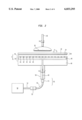
- FIG. 2 is a cross-sectional side view of one embodiment of the inventive apparatus involving use of a vacuum force.
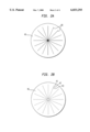
- FIG. 2A shows a top view of the polishing platen (bottom plate) used in the embodiment shown in FIG. 2.
- FIG. 2B shows a plan view of the top plate used in the embodiment shown in FIG. 2.
- FIG. 2C shows a three-dimensional view of the top plate shown in FIGS. 2 and 2B.
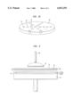
- FIG. 3 is a cross-sectional side view of one embodiment of the inventive apparatus involving use of an electromagnetic force.
- the pad be manually removable for frequent replacement, as the pad wears out after polishing a certain number of wafers (anywhere from 100 to around 700), and it needs to be continuously conditioned (or abraded), to maintain a high and stable polishing rate.
- the removability of the pads becomes a problem because in such cases the pads may need to be replaced on a daily basis.
- FIG. 1 shows a prior art pad and platen for use in a CMP polisher apparatus, which has been previously described. Since the invention addresses the manner in which the pad is secured to the platen, the type of wafer or substrate 16 or type of carrier 18 used are not critical to this invention and thus are shown in FIGS. 2 and 3 for illustrative purposes, that is, to show operation of the invention.
- the pad 30 has an upper layer 32 for contacting the wafer 16 and a backside layer 34 which faces the platen 40 when the pad and platen are secured together following the arrow C.
- the upper layer 32 may be fabricated with any materials known in the art for fabricating CMP pads.
- the backside layer 34 is comprised of a hard material having low compressibility, preferably plastic or metal.
- An advantageous material to be used for fabricating the backside layer 34 includes the polymeric material sold under the tradename MYLAR®.
- the backside layer 34 is approximately 5-20 mils thick.
- the platen 40 has a polishing table 39 which is comprised of a top plate 46 and a bottom or lower plate 40.
- the top plate 46 is preferably comprised of metal; it is perforated, that is, it has a plurality of small diameter holes traversing its width, i.e., 41, 42, 43, 44, 45, and so forth, that open to the top or major surface of the top plate 46.
- the bottom plate 40 has vacuum channels 48 running radially outward from the center of the plate, as also can be seen in FIG. 2A. Looking at FIGS. 2A and 2B, the holes are placed in the top plate 46 so that they will align with vacuum channels 48, when the two plates are placed adjacent each other.
- the channels 48 are coupled to a vacuum source 55.
- the vacuum source comprises a vacuum line 49, which runs inside a rotating shaft 50 supporting the platen 40, as well as a vacuum seal 51, a vacuum hose 52, and a vacuum switch 53.
- the vacuum line 49 is coupled to the vacuum hose 52.
- the vacuum seal 51 is placed over the connection between the vacuum line 49 and vacuum hose 52.
- the vacuum switch 53 is coupled to the vacuum hose 52 for turning the vacuum on and off.
- the vacuum hose 52 is then coupled to a vacuum 58.
- FIG. 2C shows a three-dimensional view of the top plate 46 with the vacuum holes.
- the top plate can be about 0.25-0.50 inches in thickness.
- the top plate 46 can be fabricated with a high strength, low thermal expansion metal. It is advantageous to provide holes 41, 42, 43, etc., having a diameter of about 2 millimeters and covering about 2% of the surface area of the platen 46. For example, for a platen having a diameter of 32 inches, holes ranging in number from 2000 to 3000 have proved advantageous. However, there are many ways in the hole patterns could be arranged. Different layouts, numbers of holes, and hole sizes are contemplated, although the hole pattern used may affect the holding force of the vacuum source and the uniformity of force distributed across the pad.
- the pad 30 is positioned on the perforated platen, with its hard backside layer 34 facing the platen; the pad 30 and platen 40 are placed together, following the arrow C.
- the vacuum source 55 is turned on or activated, thus exerting an attractive force on the pad; that is, the vacuum source suctions the pad toward the platen and secures the pad thereon.
- the backside layer 34 of the pad responds to the vacuum force by exerting a contact force on the upper surface of the platen 46.
- the hard backside layer 34 also serves to protect the upper layer 32 of the pad from the suctioning power of the vacuum source 55.
- An advantageous vacuum level is less than 2 ⁇ 10 -3 psi (1 Torr), which will hold the pad firmly in place during the CMP process when a platen having holes as previously described is used. It is understood, however, that the desired vacuum level may change depending upon the number and diameter of the holes in the platen, and vice versa.
- the platen 30 again has an upper layer 32 and a backside layer 36; here, the backside layer 36 is comprised of a magnetic material.
- a suitable material for fabricating the backside layer 36 includes a thin steel sheet.
- the platen 40 has an electromagnet 54 or alternatively a plurality of electromagnets (not shown), incorporated within it.
- the electromagnet 54 (or each of the plurality of electromagnets) is coupled to a switch 56 for activating or deactivating the electromagnetic force exerted by the electromagnet.
- the pad 30 is placed on the platen 40, with its magnetic backside layer 36 facing the platen; the pad 30 and platen 40 are placed together, following the arrow C.
- the electromagnet is turned on, thus exerting an attractive force on the magnetic backside layer 36; the magnetic backside layer 36 is pulled toward the platen, and exerts a corresponding force on the platen, thus securing the pad thereon.
- the electromagnet(s) can be turned off using the switch 56, and the operator can easily remove the pad 30 from the platen 40.
Abstract
Description
Claims (10)
Priority Applications (2)
| Application Number | Priority Date | Filing Date | Title |
|---|---|---|---|
| US08/947,178 US6033293A (en) | 1997-10-08 | 1997-10-08 | Apparatus for performing chemical-mechanical polishing |
| US09/450,485 US6261958B1 (en) | 1997-10-08 | 1999-11-29 | Method for performing chemical-mechanical polishing |
Applications Claiming Priority (1)
| Application Number | Priority Date | Filing Date | Title |
|---|---|---|---|
| US08/947,178 US6033293A (en) | 1997-10-08 | 1997-10-08 | Apparatus for performing chemical-mechanical polishing |
Related Child Applications (1)
| Application Number | Title | Priority Date | Filing Date |
|---|---|---|---|
| US09/450,485 Division US6261958B1 (en) | 1997-10-08 | 1999-11-29 | Method for performing chemical-mechanical polishing |
Publications (1)
| Publication Number | Publication Date |
|---|---|
| US6033293A true US6033293A (en) | 2000-03-07 |
Family
ID=25485671
Family Applications (2)
| Application Number | Title | Priority Date | Filing Date |
|---|---|---|---|
| US08/947,178 Expired - Fee Related US6033293A (en) | 1997-10-08 | 1997-10-08 | Apparatus for performing chemical-mechanical polishing |
| US09/450,485 Expired - Lifetime US6261958B1 (en) | 1997-10-08 | 1999-11-29 | Method for performing chemical-mechanical polishing |
Family Applications After (1)
| Application Number | Title | Priority Date | Filing Date |
|---|---|---|---|
| US09/450,485 Expired - Lifetime US6261958B1 (en) | 1997-10-08 | 1999-11-29 | Method for performing chemical-mechanical polishing |
Country Status (1)
| Country | Link |
|---|---|
| US (2) | US6033293A (en) |
Cited By (66)
| Publication number | Priority date | Publication date | Assignee | Title |
|---|---|---|---|---|
| US6244941B1 (en) * | 1999-03-30 | 2001-06-12 | Speedfam - Ipec Corporation | Method and apparatus for pad removal and replacement |
| US6261958B1 (en) * | 1997-10-08 | 2001-07-17 | Lucent Technologies Inc. | Method for performing chemical-mechanical polishing |
| US6336855B1 (en) * | 1999-05-17 | 2002-01-08 | Riken | Grindstone for ELID grinding and apparatus for ELID surface grinding |
| US6422921B1 (en) * | 1999-10-22 | 2002-07-23 | Applied Materials, Inc. | Heat activated detachable polishing pad |
| US20020102853A1 (en) * | 2000-12-22 | 2002-08-01 | Applied Materials, Inc. | Articles for polishing semiconductor substrates |
| US6435948B1 (en) | 2000-10-10 | 2002-08-20 | Beaver Creek Concepts Inc | Magnetic finishing apparatus |
| US6485359B1 (en) * | 2000-09-15 | 2002-11-26 | Applied Materials, Inc. | Platen arrangement for a chemical-mechanical planarization apparatus |
| US6491570B1 (en) | 1999-02-25 | 2002-12-10 | Applied Materials, Inc. | Polishing media stabilizer |
| US6503131B1 (en) | 2001-08-16 | 2003-01-07 | Applied Materials, Inc. | Integrated platen assembly for a chemical mechanical planarization system |
| US20030072639A1 (en) * | 2001-10-17 | 2003-04-17 | Applied Materials, Inc. | Substrate support |
| US20030110609A1 (en) * | 2000-08-31 | 2003-06-19 | Taylor Theodore M. | Subpad support with a releasable subpad securing element and polishing apparatus including the subpad support |
| US6592439B1 (en) * | 2000-11-10 | 2003-07-15 | Applied Materials, Inc. | Platen for retaining polishing material |
| US6592438B2 (en) * | 1999-04-02 | 2003-07-15 | Applied Materials Inc. | CMP platen with patterned surface |
| US6599175B2 (en) | 2001-08-06 | 2003-07-29 | Speedfam-Ipeca Corporation | Apparatus for distributing a fluid through a polishing pad |
| US20030209448A1 (en) * | 2002-05-07 | 2003-11-13 | Yongqi Hu | Conductive polishing article for electrochemical mechanical polishing |
| US20030220053A1 (en) * | 2000-02-17 | 2003-11-27 | Applied Materials, Inc. | Apparatus for electrochemical processing |
| US20040020788A1 (en) * | 2000-02-17 | 2004-02-05 | Applied Materials, Inc. | Contacts for electrochemical processing |
| US20040023495A1 (en) * | 2000-02-17 | 2004-02-05 | Applied Materials, Inc. | Contacts for electrochemical processing |
| US20040020789A1 (en) * | 2000-02-17 | 2004-02-05 | Applied Materials, Inc. | Conductive polishing article for electrochemical mechanical polishing |
| US20040023610A1 (en) * | 2000-02-17 | 2004-02-05 | Applied Materials, Inc. | Conductive polishing article for electrochemical mechanical polishing |
| US20040053566A1 (en) * | 2001-01-12 | 2004-03-18 | Applied Materials, Inc. | CMP platen with patterned surface |
| US6719615B1 (en) | 2000-10-10 | 2004-04-13 | Beaver Creek Concepts Inc | Versatile wafer refining |
| US20040072518A1 (en) * | 1999-04-02 | 2004-04-15 | Applied Materials, Inc. | Platen with patterned surface for chemical mechanical polishing |
| US6722949B2 (en) | 2001-03-20 | 2004-04-20 | Taiwan Semiconductors Manufacturing Co., Ltd | Ventilated platen/polishing pad assembly for chemcial mechanical polishing and method of using |
| US20040082288A1 (en) * | 1999-05-03 | 2004-04-29 | Applied Materials, Inc. | Fixed abrasive articles |
| US20040082289A1 (en) * | 2000-02-17 | 2004-04-29 | Butterfield Paul D. | Conductive polishing article for electrochemical mechanical polishing |
| US20040134792A1 (en) * | 2000-02-17 | 2004-07-15 | Applied Materials, Inc. | Conductive polishing article for electrochemical mechanical polishing |
| US20040163946A1 (en) * | 2000-02-17 | 2004-08-26 | Applied Materials, Inc. | Pad assembly for electrochemical mechanical processing |
| US6835118B2 (en) | 2001-12-14 | 2004-12-28 | Oriol, Inc. | Rigid plate assembly with polishing pad and method of using |
| US20040266085A1 (en) * | 2000-12-18 | 2004-12-30 | Applied Materials, Inc. | Integrated multi-step gap fill and all feature planarization for conductive materials |
| US20040266327A1 (en) * | 2000-02-17 | 2004-12-30 | Liang-Yuh Chen | Conductive polishing article for electrochemical mechanical polishing |
| US20050000801A1 (en) * | 2000-02-17 | 2005-01-06 | Yan Wang | Method and apparatus for electrochemical mechanical processing |
| US20050092621A1 (en) * | 2000-02-17 | 2005-05-05 | Yongqi Hu | Composite pad assembly for electrochemical mechanical processing (ECMP) |
| US20050124262A1 (en) * | 2003-12-03 | 2005-06-09 | Applied Materials, Inc. | Processing pad assembly with zone control |
| US20050161341A1 (en) * | 2000-02-17 | 2005-07-28 | Applied Materials, Inc. | Edge bead removal by an electro polishing process |
| US20050173259A1 (en) * | 2004-02-06 | 2005-08-11 | Applied Materials, Inc. | Endpoint system for electro-chemical mechanical polishing |
| US20050178666A1 (en) * | 2004-01-13 | 2005-08-18 | Applied Materials, Inc. | Methods for fabrication of a polishing article |
| US20050194681A1 (en) * | 2002-05-07 | 2005-09-08 | Yongqi Hu | Conductive pad with high abrasion |
| US20050221723A1 (en) * | 2003-10-03 | 2005-10-06 | Applied Materials, Inc. | Multi-layer polishing pad for low-pressure polishing |
| US20060030156A1 (en) * | 2004-08-05 | 2006-02-09 | Applied Materials, Inc. | Abrasive conductive polishing article for electrochemical mechanical polishing |
| US20060032749A1 (en) * | 2000-02-17 | 2006-02-16 | Liu Feng Q | Contact assembly and method for electrochemical mechanical processing |
| US20060057812A1 (en) * | 2004-09-14 | 2006-03-16 | Applied Materials, Inc. | Full sequence metal and barrier layer electrochemical mechanical processing |
| US20060060146A1 (en) * | 2004-09-21 | 2006-03-23 | Samsung Electronics Co., Ltd. | Semiconductor manufacturing apparatus and methods |
| US20060073768A1 (en) * | 2004-10-05 | 2006-04-06 | Applied Materials, Inc. | Conductive pad design modification for better wafer-pad contact |
| US20060070872A1 (en) * | 2004-10-01 | 2006-04-06 | Applied Materials, Inc. | Pad design for electrochemical mechanical polishing |
| US20060172671A1 (en) * | 2001-04-24 | 2006-08-03 | Applied Materials, Inc. | Conductive polishing article for electrochemical mechanical polishing |
| US20060219663A1 (en) * | 2005-03-31 | 2006-10-05 | Applied Materials, Inc. | Metal CMP process on one or more polishing stations using slurries with oxidizers |
| US20060228992A1 (en) * | 2002-09-16 | 2006-10-12 | Manens Antoine P | Process control in electrochemically assisted planarization |
| US20060229007A1 (en) * | 2005-04-08 | 2006-10-12 | Applied Materials, Inc. | Conductive pad |
| US20070099552A1 (en) * | 2001-04-24 | 2007-05-03 | Applied Materials, Inc. | Conductive pad with ion exchange membrane for electrochemical mechanical polishing |
| US7377836B1 (en) | 2000-10-10 | 2008-05-27 | Beaver Creek Concepts Inc | Versatile wafer refining |
| US20080125022A1 (en) * | 2006-11-24 | 2008-05-29 | National Taiwan University Of Science And Technology | Polishing apparatus and pad replacing method thereof |
| US20080153396A1 (en) * | 2003-04-25 | 2008-06-26 | Saint-Gobain Ceramics & Plastics, Inc. | Methods for machine ceramics |
| US20080153397A1 (en) * | 2006-12-20 | 2008-06-26 | Saint-Gobain Ceramics & Plastics, Inc. | Methods for machining inorganic, non-metallic workpieces |
| US20080156657A1 (en) * | 2000-02-17 | 2008-07-03 | Butterfield Paul D | Conductive polishing article for electrochemical mechanical polishing |
| US20080293343A1 (en) * | 2007-05-22 | 2008-11-27 | Yuchun Wang | Pad with shallow cells for electrochemical mechanical processing |
| US20110195640A1 (en) * | 2010-02-09 | 2011-08-11 | International Business Machines Corporation | Applying different pressures through sub-pad to fixed abrasive cmp pad |
| FR2957285A1 (en) * | 2010-03-15 | 2011-09-16 | Abaque Finance | Polishing assembly for use on turning support of polishing machine to polish e.g. optical glass, has flexible support equipped with magnetic potential source that generates assembly forces |
| CN102756340A (en) * | 2011-04-29 | 2012-10-31 | 中芯国际集成电路制造(上海)有限公司 | Chemical mechanical polishing machine and polishing pad part thereof |
| US20130316630A1 (en) * | 2012-05-04 | 2013-11-28 | Michael Rothenberg | Tool for use with dual-sided chemical mechanical planarization pad conditioner |
| US20140220864A1 (en) * | 2013-02-05 | 2014-08-07 | Ebara Corporation | Polishing apparatus |
| US20140227945A1 (en) * | 2013-02-08 | 2014-08-14 | Taiwan Semiconductor Manufacturing Co., Ltd. | Chemical mechanical planarization platen |
| US20150118944A1 (en) * | 2013-01-31 | 2015-04-30 | Ebara Corporation | Polishing apparatus, method for attaching polishing pad, and method for replacing polishing pad |
| US9022840B2 (en) | 2009-03-24 | 2015-05-05 | Saint-Gobain Abrasives, Inc. | Abrasive tool for use as a chemical mechanical planarization pad conditioner |
| CN110640633A (en) * | 2019-10-31 | 2020-01-03 | 深圳市八零联合装备有限公司 | Grinding mechanism and grinding device |
| US20200043814A1 (en) * | 2018-07-31 | 2020-02-06 | Taiwan Semiconductor Manufacturing Co., Ltd. | Systems and methods for suction pad assemblies |
Families Citing this family (16)
| Publication number | Priority date | Publication date | Assignee | Title |
|---|---|---|---|---|
| US6602380B1 (en) * | 1998-10-28 | 2003-08-05 | Micron Technology, Inc. | Method and apparatus for releasably attaching a polishing pad to a chemical-mechanical planarization machine |
| DE10032992A1 (en) * | 2000-07-06 | 2002-01-17 | Hilti Ag | Hand grinder with sanding shoe |
| US7255637B2 (en) * | 2000-09-08 | 2007-08-14 | Applied Materials, Inc. | Carrier head vibration damping |
| US7497767B2 (en) * | 2000-09-08 | 2009-03-03 | Applied Materials, Inc. | Vibration damping during chemical mechanical polishing |
| US6676497B1 (en) * | 2000-09-08 | 2004-01-13 | Applied Materials Inc. | Vibration damping in a chemical mechanical polishing system |
| US8062098B2 (en) * | 2000-11-17 | 2011-11-22 | Duescher Wayne O | High speed flat lapping platen |
| US6837774B2 (en) * | 2001-03-28 | 2005-01-04 | Taiwan Semiconductor Manufacturing Co., Ltd | Linear chemical mechanical polishing apparatus equipped with programmable pneumatic support platen and method of using |
| US6939212B1 (en) * | 2001-12-21 | 2005-09-06 | Lam Research Corporation | Porous material air bearing platen for chemical mechanical planarization |
| JP4505822B2 (en) * | 2003-04-24 | 2010-07-21 | 株式会社ニコン | Polishing apparatus, polishing method, and device manufacturing method using the polishing apparatus |
| DE102004001546A1 (en) * | 2004-01-10 | 2005-08-04 | August Rüggeberg Gmbh & Co. Kg | Tool |
| US7198549B2 (en) * | 2004-06-16 | 2007-04-03 | Cabot Microelectronics Corporation | Continuous contour polishing of a multi-material surface |
| US20060286906A1 (en) * | 2005-06-21 | 2006-12-21 | Cabot Microelectronics Corporation | Polishing pad comprising magnetically sensitive particles and method for the use thereof |
| US20080032609A1 (en) * | 2006-03-08 | 2008-02-07 | Benedict Jeffrey H | Apparatus for reducing contaminants from a chemical mechanical polishing pad |
| US8357286B1 (en) * | 2007-10-29 | 2013-01-22 | Semcon Tech, Llc | Versatile workpiece refining |
| JP6016301B2 (en) * | 2013-02-13 | 2016-10-26 | 昭和電工株式会社 | Surface processing method of single crystal SiC substrate, manufacturing method thereof, and grinding plate for surface processing of single crystal SiC substrate |
| US9481069B2 (en) * | 2013-11-06 | 2016-11-01 | Taiwan Semiconductor Manufacturing Co., Ltd. | Chemical mechanical polishing apparatus and polishing method using the same |
Citations (3)
| Publication number | Priority date | Publication date | Assignee | Title |
|---|---|---|---|---|
| US5584746A (en) * | 1993-10-18 | 1996-12-17 | Shin-Etsu Handotai Co., Ltd. | Method of polishing semiconductor wafers and apparatus therefor |
| US5704827A (en) * | 1994-10-19 | 1998-01-06 | Ebara Corporation | Polishing apparatus including cloth cartridge connected to turntable |
| US5853317A (en) * | 1996-06-27 | 1998-12-29 | Nec Corporation | Polishing pad and polishing apparatus having the same |
Family Cites Families (5)
| Publication number | Priority date | Publication date | Assignee | Title |
|---|---|---|---|---|
| US5948203A (en) * | 1996-07-29 | 1999-09-07 | Taiwan Semiconductor Manufacturing Company, Ltd. | Optical dielectric thickness monitor for chemical-mechanical polishing process monitoring |
| US5830043A (en) * | 1997-04-14 | 1998-11-03 | Ic Mic-Process, Inc. | Chemical-mechanical polishing apparatus with in-situ pad conditioner |
| US5989103A (en) * | 1997-09-19 | 1999-11-23 | Applied Materials, Inc. | Magnetic carrier head for chemical mechanical polishing |
| US6033293A (en) * | 1997-10-08 | 2000-03-07 | Lucent Technologies Inc. | Apparatus for performing chemical-mechanical polishing |
| US6059638A (en) * | 1999-01-25 | 2000-05-09 | Lucent Technologies Inc. | Magnetic force carrier and ring for a polishing apparatus |
-
1997
- 1997-10-08 US US08/947,178 patent/US6033293A/en not_active Expired - Fee Related
-
1999
- 1999-11-29 US US09/450,485 patent/US6261958B1/en not_active Expired - Lifetime
Patent Citations (3)
| Publication number | Priority date | Publication date | Assignee | Title |
|---|---|---|---|---|
| US5584746A (en) * | 1993-10-18 | 1996-12-17 | Shin-Etsu Handotai Co., Ltd. | Method of polishing semiconductor wafers and apparatus therefor |
| US5704827A (en) * | 1994-10-19 | 1998-01-06 | Ebara Corporation | Polishing apparatus including cloth cartridge connected to turntable |
| US5853317A (en) * | 1996-06-27 | 1998-12-29 | Nec Corporation | Polishing pad and polishing apparatus having the same |
Cited By (106)
| Publication number | Priority date | Publication date | Assignee | Title |
|---|---|---|---|---|
| US6261958B1 (en) * | 1997-10-08 | 2001-07-17 | Lucent Technologies Inc. | Method for performing chemical-mechanical polishing |
| US20030032380A1 (en) * | 1999-02-25 | 2003-02-13 | Applied Materials, Inc. | Polishing media stabilizer |
| US6491570B1 (en) | 1999-02-25 | 2002-12-10 | Applied Materials, Inc. | Polishing media stabilizer |
| US6244941B1 (en) * | 1999-03-30 | 2001-06-12 | Speedfam - Ipec Corporation | Method and apparatus for pad removal and replacement |
| US20040072518A1 (en) * | 1999-04-02 | 2004-04-15 | Applied Materials, Inc. | Platen with patterned surface for chemical mechanical polishing |
| US6592438B2 (en) * | 1999-04-02 | 2003-07-15 | Applied Materials Inc. | CMP platen with patterned surface |
| US20040082288A1 (en) * | 1999-05-03 | 2004-04-29 | Applied Materials, Inc. | Fixed abrasive articles |
| US6336855B1 (en) * | 1999-05-17 | 2002-01-08 | Riken | Grindstone for ELID grinding and apparatus for ELID surface grinding |
| US6422921B1 (en) * | 1999-10-22 | 2002-07-23 | Applied Materials, Inc. | Heat activated detachable polishing pad |
| US20030220053A1 (en) * | 2000-02-17 | 2003-11-27 | Applied Materials, Inc. | Apparatus for electrochemical processing |
| US20050284770A1 (en) * | 2000-02-17 | 2005-12-29 | Applied Materials, Inc. | Conductive polishing article for electrochemical mechanical polishing |
| US20080026681A1 (en) * | 2000-02-17 | 2008-01-31 | Butterfield Paul D | Conductive polishing article for electrochemical mechanical polishing |
| US20060231414A1 (en) * | 2000-02-17 | 2006-10-19 | Paul Butterfield | Contacts for electrochemical processing |
| US20080156657A1 (en) * | 2000-02-17 | 2008-07-03 | Butterfield Paul D | Conductive polishing article for electrochemical mechanical polishing |
| US7422516B2 (en) | 2000-02-17 | 2008-09-09 | Applied Materials, Inc. | Conductive polishing article for electrochemical mechanical polishing |
| US20060148381A1 (en) * | 2000-02-17 | 2006-07-06 | Applied Materials, Inc. | Pad assembly for electrochemical mechanical processing |
| US6884153B2 (en) | 2000-02-17 | 2005-04-26 | Applied Materials, Inc. | Apparatus for electrochemical processing |
| US20040020788A1 (en) * | 2000-02-17 | 2004-02-05 | Applied Materials, Inc. | Contacts for electrochemical processing |
| US20040023495A1 (en) * | 2000-02-17 | 2004-02-05 | Applied Materials, Inc. | Contacts for electrochemical processing |
| US20040020789A1 (en) * | 2000-02-17 | 2004-02-05 | Applied Materials, Inc. | Conductive polishing article for electrochemical mechanical polishing |
| US20040023610A1 (en) * | 2000-02-17 | 2004-02-05 | Applied Materials, Inc. | Conductive polishing article for electrochemical mechanical polishing |
| US20060032749A1 (en) * | 2000-02-17 | 2006-02-16 | Liu Feng Q | Contact assembly and method for electrochemical mechanical processing |
| US20080108288A1 (en) * | 2000-02-17 | 2008-05-08 | Yongqi Hu | Conductive Polishing Article for Electrochemical Mechanical Polishing |
| US7670468B2 (en) | 2000-02-17 | 2010-03-02 | Applied Materials, Inc. | Contact assembly and method for electrochemical mechanical processing |
| US6962524B2 (en) | 2000-02-17 | 2005-11-08 | Applied Materials, Inc. | Conductive polishing article for electrochemical mechanical polishing |
| US20050161341A1 (en) * | 2000-02-17 | 2005-07-28 | Applied Materials, Inc. | Edge bead removal by an electro polishing process |
| US7678245B2 (en) | 2000-02-17 | 2010-03-16 | Applied Materials, Inc. | Method and apparatus for electrochemical mechanical processing |
| US20040082289A1 (en) * | 2000-02-17 | 2004-04-29 | Butterfield Paul D. | Conductive polishing article for electrochemical mechanical polishing |
| US20040134792A1 (en) * | 2000-02-17 | 2004-07-15 | Applied Materials, Inc. | Conductive polishing article for electrochemical mechanical polishing |
| US20040163946A1 (en) * | 2000-02-17 | 2004-08-26 | Applied Materials, Inc. | Pad assembly for electrochemical mechanical processing |
| US20050133363A1 (en) * | 2000-02-17 | 2005-06-23 | Yongqi Hu | Conductive polishing article for electrochemical mechanical polishing |
| US20050092621A1 (en) * | 2000-02-17 | 2005-05-05 | Yongqi Hu | Composite pad assembly for electrochemical mechanical processing (ECMP) |
| US20040266327A1 (en) * | 2000-02-17 | 2004-12-30 | Liang-Yuh Chen | Conductive polishing article for electrochemical mechanical polishing |
| US20050000801A1 (en) * | 2000-02-17 | 2005-01-06 | Yan Wang | Method and apparatus for electrochemical mechanical processing |
| US7077733B1 (en) * | 2000-08-31 | 2006-07-18 | Micron Technology, Inc. | Subpad support with a releasable subpad securing element and polishing apparatus including the subpad support |
| US7377018B2 (en) | 2000-08-31 | 2008-05-27 | Micron Technology, Inc. | Method of replacing a subpad of a polishing apparatus |
| US20060178096A1 (en) * | 2000-08-31 | 2006-08-10 | Taylor Theodore M | Subpad support with a releasable subpad securing element and polishing apparatus including the subpad support |
| US20030110609A1 (en) * | 2000-08-31 | 2003-06-19 | Taylor Theodore M. | Subpad support with a releasable subpad securing element and polishing apparatus including the subpad support |
| US7361078B2 (en) | 2000-08-31 | 2008-04-22 | Micron Technology, Inc. | Subpad support with releasable subpad securing element and polishing apparatus |
| US7591061B2 (en) | 2000-08-31 | 2009-09-22 | Micron Technology, Inc. | Method for securing a subpad to a subpad support |
| US20040072502A1 (en) * | 2000-08-31 | 2004-04-15 | Taylor Theodore M. | Subpad support with a releasable subpad securing element and polishing apparatus including the subpad support |
| US6485359B1 (en) * | 2000-09-15 | 2002-11-26 | Applied Materials, Inc. | Platen arrangement for a chemical-mechanical planarization apparatus |
| US6719615B1 (en) | 2000-10-10 | 2004-04-13 | Beaver Creek Concepts Inc | Versatile wafer refining |
| US7377836B1 (en) | 2000-10-10 | 2008-05-27 | Beaver Creek Concepts Inc | Versatile wafer refining |
| US6435948B1 (en) | 2000-10-10 | 2002-08-20 | Beaver Creek Concepts Inc | Magnetic finishing apparatus |
| US6592439B1 (en) * | 2000-11-10 | 2003-07-15 | Applied Materials, Inc. | Platen for retaining polishing material |
| US7323095B2 (en) | 2000-12-18 | 2008-01-29 | Applied Materials, Inc. | Integrated multi-step gap fill and all feature planarization for conductive materials |
| US20040266085A1 (en) * | 2000-12-18 | 2004-12-30 | Applied Materials, Inc. | Integrated multi-step gap fill and all feature planarization for conductive materials |
| US20070066200A9 (en) * | 2000-12-22 | 2007-03-22 | Applied Materials, Inc. | Perforation and grooving for polishing articles |
| US20020102853A1 (en) * | 2000-12-22 | 2002-08-01 | Applied Materials, Inc. | Articles for polishing semiconductor substrates |
| US20060217049A1 (en) * | 2000-12-22 | 2006-09-28 | Applied Materials, Inc. | Perforation and grooving for polishing articles |
| US20040053566A1 (en) * | 2001-01-12 | 2004-03-18 | Applied Materials, Inc. | CMP platen with patterned surface |
| US6722949B2 (en) | 2001-03-20 | 2004-04-20 | Taiwan Semiconductors Manufacturing Co., Ltd | Ventilated platen/polishing pad assembly for chemcial mechanical polishing and method of using |
| US20070099552A1 (en) * | 2001-04-24 | 2007-05-03 | Applied Materials, Inc. | Conductive pad with ion exchange membrane for electrochemical mechanical polishing |
| US20070066201A1 (en) * | 2001-04-24 | 2007-03-22 | Applied Materials, Inc. | Conductive polishing article for electrochemical mechanical polishing |
| US20060172671A1 (en) * | 2001-04-24 | 2006-08-03 | Applied Materials, Inc. | Conductive polishing article for electrochemical mechanical polishing |
| US6599175B2 (en) | 2001-08-06 | 2003-07-29 | Speedfam-Ipeca Corporation | Apparatus for distributing a fluid through a polishing pad |
| US6503131B1 (en) | 2001-08-16 | 2003-01-07 | Applied Materials, Inc. | Integrated platen assembly for a chemical mechanical planarization system |
| US20030072639A1 (en) * | 2001-10-17 | 2003-04-17 | Applied Materials, Inc. | Substrate support |
| US6835118B2 (en) | 2001-12-14 | 2004-12-28 | Oriol, Inc. | Rigid plate assembly with polishing pad and method of using |
| US20030209448A1 (en) * | 2002-05-07 | 2003-11-13 | Yongqi Hu | Conductive polishing article for electrochemical mechanical polishing |
| US20050194681A1 (en) * | 2002-05-07 | 2005-09-08 | Yongqi Hu | Conductive pad with high abrasion |
| US20060228992A1 (en) * | 2002-09-16 | 2006-10-12 | Manens Antoine P | Process control in electrochemically assisted planarization |
| US7294038B2 (en) | 2002-09-16 | 2007-11-13 | Applied Materials, Inc. | Process control in electrochemically assisted planarization |
| US8025808B2 (en) | 2003-04-25 | 2011-09-27 | Saint-Gobain Ceramics & Plastics, Inc. | Methods for machine ceramics |
| US20080153396A1 (en) * | 2003-04-25 | 2008-06-26 | Saint-Gobain Ceramics & Plastics, Inc. | Methods for machine ceramics |
| US8066552B2 (en) | 2003-10-03 | 2011-11-29 | Applied Materials, Inc. | Multi-layer polishing pad for low-pressure polishing |
| US20050221723A1 (en) * | 2003-10-03 | 2005-10-06 | Applied Materials, Inc. | Multi-layer polishing pad for low-pressure polishing |
| US20050124262A1 (en) * | 2003-12-03 | 2005-06-09 | Applied Materials, Inc. | Processing pad assembly with zone control |
| US7186164B2 (en) | 2003-12-03 | 2007-03-06 | Applied Materials, Inc. | Processing pad assembly with zone control |
| US20050178666A1 (en) * | 2004-01-13 | 2005-08-18 | Applied Materials, Inc. | Methods for fabrication of a polishing article |
| US20050173259A1 (en) * | 2004-02-06 | 2005-08-11 | Applied Materials, Inc. | Endpoint system for electro-chemical mechanical polishing |
| US20060030156A1 (en) * | 2004-08-05 | 2006-02-09 | Applied Materials, Inc. | Abrasive conductive polishing article for electrochemical mechanical polishing |
| US20060057812A1 (en) * | 2004-09-14 | 2006-03-16 | Applied Materials, Inc. | Full sequence metal and barrier layer electrochemical mechanical processing |
| US20060260951A1 (en) * | 2004-09-14 | 2006-11-23 | Liu Feng Q | Full Sequence Metal and Barrier Layer Electrochemical Mechanical Processing |
| US20060060146A1 (en) * | 2004-09-21 | 2006-03-23 | Samsung Electronics Co., Ltd. | Semiconductor manufacturing apparatus and methods |
| US20060070872A1 (en) * | 2004-10-01 | 2006-04-06 | Applied Materials, Inc. | Pad design for electrochemical mechanical polishing |
| US20060073768A1 (en) * | 2004-10-05 | 2006-04-06 | Applied Materials, Inc. | Conductive pad design modification for better wafer-pad contact |
| US20060219663A1 (en) * | 2005-03-31 | 2006-10-05 | Applied Materials, Inc. | Metal CMP process on one or more polishing stations using slurries with oxidizers |
| US20060229007A1 (en) * | 2005-04-08 | 2006-10-12 | Applied Materials, Inc. | Conductive pad |
| US7572173B2 (en) * | 2006-11-24 | 2009-08-11 | National Taiwan University Of Science And Technology | Polishing apparatus and pad replacing method thereof |
| US20080125022A1 (en) * | 2006-11-24 | 2008-05-29 | National Taiwan University Of Science And Technology | Polishing apparatus and pad replacing method thereof |
| US20080153397A1 (en) * | 2006-12-20 | 2008-06-26 | Saint-Gobain Ceramics & Plastics, Inc. | Methods for machining inorganic, non-metallic workpieces |
| US8168075B2 (en) * | 2006-12-20 | 2012-05-01 | Laconto Ronald W | Methods for machining inorganic, non-metallic workpieces |
| US20080293343A1 (en) * | 2007-05-22 | 2008-11-27 | Yuchun Wang | Pad with shallow cells for electrochemical mechanical processing |
| US9022840B2 (en) | 2009-03-24 | 2015-05-05 | Saint-Gobain Abrasives, Inc. | Abrasive tool for use as a chemical mechanical planarization pad conditioner |
| US8858300B2 (en) * | 2010-02-09 | 2014-10-14 | International Business Machines Corporation | Applying different pressures through sub-pad to fixed abrasive CMP pad |
| US20110195640A1 (en) * | 2010-02-09 | 2011-08-11 | International Business Machines Corporation | Applying different pressures through sub-pad to fixed abrasive cmp pad |
| FR2957285A1 (en) * | 2010-03-15 | 2011-09-16 | Abaque Finance | Polishing assembly for use on turning support of polishing machine to polish e.g. optical glass, has flexible support equipped with magnetic potential source that generates assembly forces |
| CN102756340A (en) * | 2011-04-29 | 2012-10-31 | 中芯国际集成电路制造(上海)有限公司 | Chemical mechanical polishing machine and polishing pad part thereof |
| US20120276825A1 (en) * | 2011-04-29 | 2012-11-01 | Semiconductor Manufacturing International (Shanghai) Corporation | Chemical mechanical polisher and polishing pad component thereof |
| US8845398B2 (en) * | 2011-04-29 | 2014-09-30 | Semiconductor Manufacturing International (Shanghai) Corporation | Chemical mechanical polisher and polishing pad component thereof |
| CN102756340B (en) * | 2011-04-29 | 2015-04-22 | 中芯国际集成电路制造(上海)有限公司 | Chemical mechanical polishing machine and polishing pad part thereof |
| US20130316630A1 (en) * | 2012-05-04 | 2013-11-28 | Michael Rothenberg | Tool for use with dual-sided chemical mechanical planarization pad conditioner |
| US20150118944A1 (en) * | 2013-01-31 | 2015-04-30 | Ebara Corporation | Polishing apparatus, method for attaching polishing pad, and method for replacing polishing pad |
| CN104968472A (en) * | 2013-01-31 | 2015-10-07 | 株式会社荏原制作所 | Polishing device, method for applying polishing pad, and method for replacing polishing pad |
| US9211629B2 (en) * | 2013-02-05 | 2015-12-15 | Ebara Corporation | Polishing apparatus |
| US20140220864A1 (en) * | 2013-02-05 | 2014-08-07 | Ebara Corporation | Polishing apparatus |
| US20140227945A1 (en) * | 2013-02-08 | 2014-08-14 | Taiwan Semiconductor Manufacturing Co., Ltd. | Chemical mechanical planarization platen |
| US20200043814A1 (en) * | 2018-07-31 | 2020-02-06 | Taiwan Semiconductor Manufacturing Co., Ltd. | Systems and methods for suction pad assemblies |
| CN110774164A (en) * | 2018-07-31 | 2020-02-11 | 台湾积体电路制造股份有限公司 | Chemical mechanical planarization system and method |
| CN110774164B (en) * | 2018-07-31 | 2021-10-15 | 台湾积体电路制造股份有限公司 | Chemical mechanical planarization system and method |
| US11328965B2 (en) * | 2018-07-31 | 2022-05-10 | Taiwan Semiconductor Manufacturing Co., Ltd. | Systems and methods for suction pad assemblies |
| US20220246483A1 (en) * | 2018-07-31 | 2022-08-04 | Taiwan Semiconductor Manufacturing Co., Ltd. | Systems and methods for suction pad assemblies |
| CN110640633A (en) * | 2019-10-31 | 2020-01-03 | 深圳市八零联合装备有限公司 | Grinding mechanism and grinding device |
| CN110640633B (en) * | 2019-10-31 | 2022-03-08 | 深圳市八零联合装备有限公司 | Grinding mechanism and grinding device |
Also Published As
| Publication number | Publication date |
|---|---|
| US6261958B1 (en) | 2001-07-17 |
Similar Documents
| Publication | Publication Date | Title |
|---|---|---|
| US6033293A (en) | Apparatus for performing chemical-mechanical polishing | |
| US6241585B1 (en) | Apparatus and method for chemical mechanical polishing | |
| US5944583A (en) | Composite polish pad for CMP | |
| US6036587A (en) | Carrier head with layer of conformable material for a chemical mechanical polishing system | |
| US5885135A (en) | CMP wafer carrier for preferential polishing of a wafer | |
| JP4601171B2 (en) | Carrier head for chemical mechanical polishing of substrates | |
| JP4489903B2 (en) | Improved CMP platen with patterned surface | |
| US6050882A (en) | Carrier head to apply pressure to and retain a substrate | |
| JP4086722B2 (en) | Substrate holding device and polishing device | |
| US6143127A (en) | Carrier head with a retaining ring for a chemical mechanical polishing system | |
| KR19980079423A (en) | Polishing pads for polishing semiconductors and methods of polishing semiconductor wafers | |
| JPH09155730A (en) | Holding tool used for polishing workpiece and its manufacture | |
| US6569771B2 (en) | Carrier head for chemical mechanical polishing | |
| JP4750250B2 (en) | Carrier head with modified flexible membrane | |
| EP0860238B1 (en) | Polishing apparatus | |
| KR101411293B1 (en) | Polishing head, polishing apparatus and work removing method | |
| US6273794B1 (en) | Apparatus and method for grinding a semiconductor wafer surface | |
| KR20000057941A (en) | Chemical mechanical polishing with a moving polishing sheet | |
| KR100807046B1 (en) | Chemical mechanical polishing apparatus | |
| JPH10180626A (en) | Carrier head having suitable material layer for chemical and mechanical grinding system | |
| JP3856634B2 (en) | Substrate holding device and polishing apparatus provided with the substrate holding device | |
| JPH09246218A (en) | Polishing method/device | |
| JPH11333677A (en) | Polishing device for substrate | |
| KR100583279B1 (en) | Backing film for semiconductor wafer polishing apparatus | |
| JP2003158104A (en) | Polishing device |
Legal Events
| Date | Code | Title | Description |
|---|---|---|---|
| AS | Assignment |
Owner name: LUCENT TECHNOLOGIES INC., NEW JERSEY Free format text: ASSIGNMENT OF ASSIGNORS INTEREST;ASSIGNORS:CREVASSE, ANNETTE MARGARET;MAURY, ALVARO;PATEL, SANJAY;AND OTHERS;REEL/FRAME:009036/0720;SIGNING DATES FROM 19980225 TO 19980227 |
|
| FEPP | Fee payment procedure |
Free format text: PAYOR NUMBER ASSIGNED (ORIGINAL EVENT CODE: ASPN); ENTITY STATUS OF PATENT OWNER: LARGE ENTITY |
|
| AS | Assignment |
Owner name: THE CHASE MANHATTAN BANK, AS COLLATERAL AGENT, TEX Free format text: CONDITIONAL ASSIGNMENT OF AND SECURITY INTEREST IN PATENT RIGHTS;ASSIGNOR:LUCENT TECHNOLOGIES INC. (DE CORPORATION);REEL/FRAME:011722/0048 Effective date: 20010222 |
|
| FPAY | Fee payment |
Year of fee payment: 4 |
|
| AS | Assignment |
Owner name: LUCENT TECHNOLOGIES INC., NEW JERSEY Free format text: TERMINATION AND RELEASE OF SECURITY INTEREST IN PATENT RIGHTS;ASSIGNOR:JPMORGAN CHASE BANK, N.A. (FORMERLY KNOWN AS THE CHASE MANHATTAN BANK), AS ADMINISTRATIVE AGENT;REEL/FRAME:018590/0047 Effective date: 20061130 |
|
| REMI | Maintenance fee reminder mailed | ||
| LAPS | Lapse for failure to pay maintenance fees | ||
| STCH | Information on status: patent discontinuation |
Free format text: PATENT EXPIRED DUE TO NONPAYMENT OF MAINTENANCE FEES UNDER 37 CFR 1.362 |
|
| FP | Lapsed due to failure to pay maintenance fee |
Effective date: 20080307 |