US6033101A - Cable television radio frequency and AC Power multitap - Google Patents
Cable television radio frequency and AC Power multitap Download PDFInfo
- Publication number
- US6033101A US6033101A US08/350,801 US35080194A US6033101A US 6033101 A US6033101 A US 6033101A US 35080194 A US35080194 A US 35080194A US 6033101 A US6033101 A US 6033101A
- Authority
- US
- United States
- Prior art keywords
- subscriber
- video signal
- main
- cable
- conductor
- Prior art date
- Legal status (The legal status is an assumption and is not a legal conclusion. Google has not performed a legal analysis and makes no representation as to the accuracy of the status listed.)
- Expired - Lifetime
Links
- 239000004020 conductor Substances 0.000 claims abstract description 119
- 238000010168 coupling process Methods 0.000 claims abstract description 34
- 230000008878 coupling Effects 0.000 claims abstract description 33
- 238000005859 coupling reaction Methods 0.000 claims abstract description 33
- 238000004891 communication Methods 0.000 claims abstract description 4
- 239000003990 capacitor Substances 0.000 claims description 23
- 239000002184 metal Substances 0.000 claims description 12
- 238000000605 extraction Methods 0.000 claims description 8
- 238000001914 filtration Methods 0.000 claims description 8
- 230000005670 electromagnetic radiation Effects 0.000 claims description 7
- 230000005540 biological transmission Effects 0.000 claims description 6
- 239000003989 dielectric material Substances 0.000 claims description 3
- HQQADJVZYDDRJT-UHFFFAOYSA-N ethene;prop-1-ene Chemical group C=C.CC=C HQQADJVZYDDRJT-UHFFFAOYSA-N 0.000 claims description 2
- 229920000515 polycarbonate Polymers 0.000 claims description 2
- 239000004417 polycarbonate Substances 0.000 claims description 2
- XLYOFNOQVPJJNP-UHFFFAOYSA-N water Substances O XLYOFNOQVPJJNP-UHFFFAOYSA-N 0.000 claims description 2
- 230000003139 buffering effect Effects 0.000 claims 2
- 238000000034 method Methods 0.000 description 8
- 238000009434 installation Methods 0.000 description 7
- 230000007613 environmental effect Effects 0.000 description 4
- 239000000356 contaminant Substances 0.000 description 3
- 238000010586 diagram Methods 0.000 description 3
- 235000012773 waffles Nutrition 0.000 description 3
- 238000003780 insertion Methods 0.000 description 2
- 230000037431 insertion Effects 0.000 description 2
- 230000001154 acute effect Effects 0.000 description 1
- 238000010276 construction Methods 0.000 description 1
- 230000007812 deficiency Effects 0.000 description 1
- 238000013461 design Methods 0.000 description 1
- 238000011161 development Methods 0.000 description 1
- 230000018109 developmental process Effects 0.000 description 1
- 238000005516 engineering process Methods 0.000 description 1
- 239000000284 extract Substances 0.000 description 1
- 230000005294 ferromagnetic effect Effects 0.000 description 1
- 239000000463 material Substances 0.000 description 1
- 239000000155 melt Substances 0.000 description 1
- 239000002689 soil Substances 0.000 description 1
Images


Classifications
-
- H—ELECTRICITY
- H04—ELECTRIC COMMUNICATION TECHNIQUE
- H04N—PICTORIAL COMMUNICATION, e.g. TELEVISION
- H04N7/00—Television systems
- H04N7/10—Adaptations for transmission by electrical cable
- H04N7/102—Circuits therefor, e.g. noise reducers, equalisers, amplifiers
- H04N7/104—Switchers or splitters
-
- H—ELECTRICITY
- H01—ELECTRIC ELEMENTS
- H01R—ELECTRICALLY-CONDUCTIVE CONNECTIONS; STRUCTURAL ASSOCIATIONS OF A PLURALITY OF MUTUALLY-INSULATED ELECTRICAL CONNECTING ELEMENTS; COUPLING DEVICES; CURRENT COLLECTORS
- H01R24/00—Two-part coupling devices, or either of their cooperating parts, characterised by their overall structure
- H01R24/38—Two-part coupling devices, or either of their cooperating parts, characterised by their overall structure having concentrically or coaxially arranged contacts
- H01R24/40—Two-part coupling devices, or either of their cooperating parts, characterised by their overall structure having concentrically or coaxially arranged contacts specially adapted for high frequency
- H01R24/54—Intermediate parts, e.g. adapters, splitters or elbows
- H01R24/542—Adapters
-
- H—ELECTRICITY
- H03—ELECTRONIC CIRCUITRY
- H03H—IMPEDANCE NETWORKS, e.g. RESONANT CIRCUITS; RESONATORS
- H03H7/00—Multiple-port networks comprising only passive electrical elements as network components
- H03H7/48—Networks for connecting several sources or loads, working on the same frequency or frequency band, to a common load or source
- H03H7/482—Networks for connecting several sources or loads, working on the same frequency or frequency band, to a common load or source particularly adapted for use in common antenna systems
-
- H—ELECTRICITY
- H04—ELECTRIC COMMUNICATION TECHNIQUE
- H04B—TRANSMISSION
- H04B3/00—Line transmission systems
- H04B3/54—Systems for transmission via power distribution lines
- H04B3/56—Circuits for coupling, blocking, or by-passing of signals
-
- H—ELECTRICITY
- H04—ELECTRIC COMMUNICATION TECHNIQUE
- H04H—BROADCAST COMMUNICATION
- H04H20/00—Arrangements for broadcast or for distribution combined with broadcast
- H04H20/65—Arrangements characterised by transmission systems for broadcast
- H04H20/76—Wired systems
- H04H20/84—Wired systems combined with power distribution network
-
- H—ELECTRICITY
- H01—ELECTRIC ELEMENTS
- H01R—ELECTRICALLY-CONDUCTIVE CONNECTIONS; STRUCTURAL ASSOCIATIONS OF A PLURALITY OF MUTUALLY-INSULATED ELECTRICAL CONNECTING ELEMENTS; COUPLING DEVICES; CURRENT COLLECTORS
- H01R2103/00—Two poles
-
- H—ELECTRICITY
- H01—ELECTRIC ELEMENTS
- H01R—ELECTRICALLY-CONDUCTIVE CONNECTIONS; STRUCTURAL ASSOCIATIONS OF A PLURALITY OF MUTUALLY-INSULATED ELECTRICAL CONNECTING ELEMENTS; COUPLING DEVICES; CURRENT COLLECTORS
- H01R2201/00—Connectors or connections adapted for particular applications
- H01R2201/18—Connectors or connections adapted for particular applications for television
-
- H—ELECTRICITY
- H04—ELECTRIC COMMUNICATION TECHNIQUE
- H04B—TRANSMISSION
- H04B2203/00—Indexing scheme relating to line transmission systems
- H04B2203/54—Aspects of powerline communications not already covered by H04B3/54 and its subgroups
- H04B2203/5404—Methods of transmitting or receiving signals via power distribution lines
- H04B2203/5425—Methods of transmitting or receiving signals via power distribution lines improving S/N by matching impedance, noise reduction, gain control
-
- H—ELECTRICITY
- H04—ELECTRIC COMMUNICATION TECHNIQUE
- H04B—TRANSMISSION
- H04B2203/00—Indexing scheme relating to line transmission systems
- H04B2203/54—Aspects of powerline communications not already covered by H04B3/54 and its subgroups
- H04B2203/5429—Applications for powerline communications
- H04B2203/5441—Wireless systems or telephone
-
- H—ELECTRICITY
- H04—ELECTRIC COMMUNICATION TECHNIQUE
- H04B—TRANSMISSION
- H04B2203/00—Indexing scheme relating to line transmission systems
- H04B2203/54—Aspects of powerline communications not already covered by H04B3/54 and its subgroups
- H04B2203/5429—Applications for powerline communications
- H04B2203/5445—Local network
-
- H—ELECTRICITY
- H04—ELECTRIC COMMUNICATION TECHNIQUE
- H04B—TRANSMISSION
- H04B2203/00—Indexing scheme relating to line transmission systems
- H04B2203/54—Aspects of powerline communications not already covered by H04B3/54 and its subgroups
- H04B2203/5429—Applications for powerline communications
- H04B2203/545—Audio/video application, e.g. interphone
-
- H—ELECTRICITY
- H04—ELECTRIC COMMUNICATION TECHNIQUE
- H04B—TRANSMISSION
- H04B2203/00—Indexing scheme relating to line transmission systems
- H04B2203/54—Aspects of powerline communications not already covered by H04B3/54 and its subgroups
- H04B2203/5462—Systems for power line communications
- H04B2203/5483—Systems for power line communications using coupling circuits
-
- H—ELECTRICITY
- H04—ELECTRIC COMMUNICATION TECHNIQUE
- H04B—TRANSMISSION
- H04B2203/00—Indexing scheme relating to line transmission systems
- H04B2203/54—Aspects of powerline communications not already covered by H04B3/54 and its subgroups
- H04B2203/5462—Systems for power line communications
- H04B2203/5491—Systems for power line communications using filtering and bypassing
Definitions
- This invention relates to cable television, and more particularly relates to a tap for delivering electrical power to subscriber substations from a main cable capable of transmitting a main video signal and a main power signal on a cable conductor.
- the applicants have discovered techniques for supplying AC power signals to a multiplicity of subscriber substations with only a minimal loss to the video signal. For example, in a typical tap for supplying subscriber substations, the applicants have been able to supply power from the cable power signal with an increase in insertion loss of only about 0.2 decibels of radio frequency energy from the video signal when compared to a tap that does not supply power to the substation.
- the cable television industry has long sought a means of quickly connecting a cable conductor to a tap without creating variable capacitance and without requiring undue labor by an installer.
- the coupling technique must match as nearly as possible the characteristic impedance of the cable conductor.
- the invention is suitable for use in connection with a system for distributing information to subscriber substations, including a main cable for transmitting a main video signal and a main power signal on a cable conductor having a predetermined cable characteristic impedance. It has been discovered that both video signals and power signals can be supplied from the cable conductor to numerous subscriber substations by providing a first means for coupling the video signal and the main power signal from a cable conductor to an improved tap. Means are provided in the tap for generating a subscriber video signal by extracting a predetermined portion of the main video signal received from the first coupling means. The extracted subscriber video signal is transmitted to the subscriber substations on video cable.
- a subscriber power signal is also generated by extracting a predetermined portion of the main power signal received from the first coupling means.
- the extracted subscriber power signal is transmitted to the subscriber substations on subscriber power lines.
- the subscriber video cable and subscriber power lines are combined into a single cable.
- the unextracted portion of the main video signal and the main power signal are transmitted to a second main cable which may extend to additional taps capable of supplying additional subscriber substations.
- Another feature of the invention is useful in a tap for delivering power and video signals to subscriber substations from a main cable transmitting a main video signal and a main power signal on a cable conductor having a predetermined cable characteristic impedance.
- the installation of the cable in the tap is greatly simplified by using a clip for receiving the cable conductor.
- the clip includes first and second opposed gripping surfaces for gripping the cable conductor and a spring section for urging the first and second gripping surfaces toward each other with a predetermined force.
- the tap includes a port having a threaded inner wall and a circuit presenting a predetermined terminal impedance to the main cable different from the characteristic impedance of the cable.
- the applicants have discovered an improved insert for guiding the cable conductor through the port and for adjusting the terminal impedance to more nearly equal the characteristic impedance.
- the insert includes a body defining a hole having a diameter larger than the diameter of the cable conductor and also having a generally conical funnel for guiding the cable conductor through the hole.
- the funnel also guides the cable conductor into the previously described clip.
- the terminal impedance of the tap may be adjusted to more nearly equally characteristic impedance of the cable.
- the previously described clip and the insert may be combined to provide an improved means of coupling the cable to the tap with a degree of efficiency, ease and impedance matching capability unappreciated by the prior art.
- Another feature of the invention is useful in connection with a tap for delivering video signals to subscriber substations from a main cable transmitting a main video signal and a main power signal to a cable conductor.
- the tap preferably includes a circuit for extracting a predetermined portion of the main video signal for transmission to the subscriber substations.
- the applicants have discovered improved apparatus for confining electromagnetic radiation inside the tap and for preventing rain and other environmental contaminants from entering the tap.
- the second tongue is inserted in the first groove in contacting relationship in order to prevent electromagnetic radiation from escaping from the housing.
- the combination also includes an integrally formed seal having a first member inserted in the second groove and having a second member engaged by the first tongue.
- the tap includes an input port for receiving the main cable and a coupler for generating a subscriber video signal by extracting a predetermined portion of the main video signal.
- the coupler also includes an input for receiving the main video signal, a first output for transmitting the extracted predetermined portion of the main video signal and a second output for transmitting an unextracted portion of the main video signal to an output port.
- the reversing apparatus includes a first conductor coupled to the input of the coupler, a second conductor coupled to the second output of the coupler, a third conductor coupled to the input port, and a fourth conductor coupled to the output port.
- a base is movable between first and second positions.
- a fifth conductor is mounted on the base and is operable when the base is in the first position for coupling the first and fourth conductors and is operable when the base is in the second position for coupling the first and third conductors.
- a sixth conductor also is mounted on the base and is operable when the base is in the first position for coupling the second and third conductors and is operable when the base is in the second position for coupling the second and fourth conductors.
- the main video signal can be coupled to the input of the coupler, irrespective of whether the main video signal is received through the input port or through the output port.
- Another aspect of the invention is useful in a tap for delivery video signals to subscriber substations from a main cable transmitting a main video signal having a predetermined pass band and a main power signal on a cable conductor.
- the tap includes a coupler for generating a subscriber video signal by extracting a predetermined portion of the main video signal.
- power can be supplied to the subscriber substations from the main cable by providing a means for generating a subscriber power signal by extracting a predetermined portion of the main power signal.
- the means for generating has a resonant frequency outside the pass band of the cable.
- the subscriber power signal is transmitted to the subscriber substations. Using such techniques, reliable AC power signals can be provided to numerous subscriber substations from a main cable carrying both video and power signals with a degree of efficiency and economy previously unknown.
- Yet another feature of the invention may be used in a tap for delivering video signals to subscriber substations from a main cable transmitting a main video signal and a main power signal on a cable conductor.
- the tap preferably includes a coupler for generating a subscriber video signal by extracting a predetermined portion of the main video signal.
- the main cable comprises a first shield connected to ground at a location remote from the subscriber substation.
- the subscriber substation comprises a subscriber ground connection connected to ground adjacent the subscriber substation.
- the extracted predetermined portion of the main video signal is transmitted to the subscriber substations on a line having second shield connected to the subscriber ground connection and a line signal conductor for transmitting the subscriber video signal to the subscriber substation.
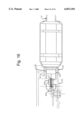
- FIG. 1 is a schematic, fragmentary block diagram illustrating an exemplary group of subscriber substations that are connected to a tap made in accordance with a preferred mode of the present invention
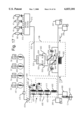
- FIG. 2 is a schematic system block diagram of the tap shown in FIG. 1;
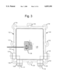
- FIG. 3 is a bottom plan view of a preferred form of case for the tap illustrated in FIG. 1;
- FIG. 4 is a top plan view of the tap case shown in FIG. 3 from which one of the covers has been removed for clarity;
- FIG. 5 is a cross sectional view of the tap case taken along line 5--5 in FIG. 4;
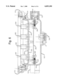
- FIG. 6 is a cross sectional view taken along line 6--6 in FIG. 4 with current limiters 687 and 688 removed and with views of clips 397-400 and ports 134 and 135 added taken along line 6'--6' in FIG. 4;
- FIG. 6A is an enlarged, cross sectional view of a portion of the apparatus shown in FIG. 6;
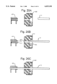
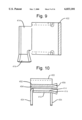
- FIG. 7 is a top plan view of a preferred form of clip made in accordance with one aspect of the invention.
- FIG. 8 is a front elevational view of the clip as shown in FIG. 7;
- FIG. 9 is a cross sectional view taken along line 9--9 in FIG. 8;
- FIG. 10 is a cross sectional view taken along line 10--10 in FIG. 7;
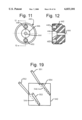
- FIG. 11 is a front elevational view of a preferred form of insert made in accordance with one aspect of the invention.
- FIG. 12 is a cross sectional view taken along line 12--12 of FIG. 11;
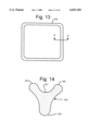
- FIG. 13 is a top plan view of a preferred form of gasket for the case as shown in FIG. 5;
- FIG. 14 is a cross sectional view taken along line 14--14 in FIG. 13;
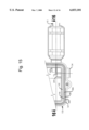
- FIG. 15 is a fragmentary view of an exemplary main cable as connected to a modified form of the case as shown in FIG. 4 with the cover and top removed for clarity and with a mounting flange relocated;
- FIG. 16 is a cross sectional view taken along line 16--16 in FIG. 15;
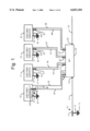
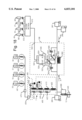
- FIG. 17 is an electrical schematic block diagram showing a preferred form of circuitry made in accordance with one aspect of the invention.
- FIG. 18 is an illustration of the circuitry as shown in FIG. 17 with a reversing block rotated to reverse the connections for part of the circuit;
- FIG. 19 is a diagrammatic view of the reversing block shown in FIGS. 17 and 18.
- FIGS. 20A-20C are fragmentary, cross sectional views illustrating the ability of a preferred form of insert to guide a cable conductor into a preferred form of clip.
- the preferred embodiment of the invention may be used in connection with a main coaxial cable 10 of a cable television system that includes a center cable conductor 12 surrounded by a shield 14 throughout substantially the entire length of conductor 12.
- the cable conductor and shield are separated by a dielectric (not shown).
- Shield 14 is connected through a ground connection 16 to a ground point 18.
- Cable conductor 12 transmits a main video signal having a pass band from 5 megahertz to at least 1 gigahertz.
- Conductor 12 also transmits a 60 hertz 60 volt AC main power signal.
- cable 10 may be used to supply both video signals and power signals to a multiplicity of subscriber substations (e.g., residential homes).
- subscriber substations e.g., residential homes.
- the subscriber substations may include communication devices, such as telephones, which must have power independent of the normal AC electrical power supplied by electrical utilities.
- the electrical systems and the subscriber substations are connected through ground conductors 35-38 to ground points 40-43, respectively. Points 40-43 are remote from ground point 18.
- Video signals corresponding to the video signal on cable 10 are supplied through coaxial line signal conductors 45-48 that are protected by metallic shields 50-53 throughout substantially their entire length. A substantial portion of the length of shields 50-53 has been removed in FIG. 1 for clarity.
- the applicants have discovered techniques disclosed in the specification for also supplying to substations 30-33 with subscriber AC power signals extracted from cable 10.
- the subscriber power signals are transmitted over power line conductors 55-58.
- Each of conductors 55-58 preferably comprises a twisted pair of conductors.
- conductors 45-48, 55-58 and shields 50-53 are combined in a single cable that can be conveniently routed to subscriber substations.
- unique tap 100 capable of supplying from cable 10 both video signals and power signals to subscriber substations 30-33 includes an input port 102 having internal threads 103 (FIG. 16) and a mounting ridge 104 (FIG. 16). Tap 100 also includes an output port 105 constructed identically to input port 102.
- tap 100 is enclosed by and supported by a tap case 130 comprising a metal base 132.
- Base 132 is fitted with alternate ports 134 and 135 that may be used as input and output ports in place of ports 102 and 105, depending on the orientation of the tap case during installation.
- ports 102 and 105 are closed by threaded plugs 136 and 137. The plugs may be removed from ports 102 and 105 and threaded into ports 134 and 135 in the event that ports 102 and 105 are connected to cables 10 and 118.
- Each of ports 102, 105, 134 and 135 is identical and may receive cable 10 or 118.
- Tap case 130 includes a clamp 138 (FIG. 3) bolted to a bottom plate 140 in order to facilitate installation.
- Base 132 also includes sidewalls 142 that are cast to include a tongue 144 (FIGS. 5 and 6A) defining a closed curve and a companion groove 145 also defining a closed curve.
- Groove 145 has an inverted trapezoid shape that defines sidewalls 146 and 147.
- Base 132 includes mounting flanges 152-159 that are integrally formed with sidewall 142.
- tap case 130 includes a metal cover 200 having a bottom plate 202 defining a bottom surface 204 and a top surface 206 (FIG. 6).
- Cover 200 also includes a sidewall 210 that is cast to include a groove 212 defining a closed curve and a companion tongue 214 also defining a closed curve.
- cover 200 also includes power distribution walls 221-224 arranged as shown.
- Wall 223 defines a cut-out section 226 having an upper edge 227.
- Wall 223 also includes a top edge 230 defining a gasket groove 232 that receives a gasket 234 having a waffle area 235 allowing for the passage of conductors and a circular cross-section area 236 that prevents rainwater from entering.
- Bottom surface 204 of bottom plate 202 bears mounting studs and screws 241-244 that mount a conventional circuit board 250.
- Top surface 206 of bottom plate 202 bears mounting studs and screws 261 and 262 that are used to mount another circuit board 264.
- Metal cover 200 is integrally formed with conventional mounting cylinders, such as cylinders 282 and 284, that receive conventional mounting bolts 302-309 that hold cover 200 securely to base 132.
- tap case 130 also includes a cover 320 having a top 322 and a sidewall 324 defining a lower edge 326.
- Cover 320 defines a cut-out section 328 having a lower edge 330 that comates with upper edge 227 to define an opening 332 for receiving twisted pair power lines 55-58 through waffle area 235 of gasket 234.
- Cover 320 and cover 200 define a closed compartment 370 for housing power distribution components described hereafter.
- the unique shape of covers 200 and 320, as well as the configuration of gasket 234, are an important feature which prevent electromagnetic radiation from escaping compartment 370 and inhibit rainwater or other environmental contaminants from entering compartment 370.
- Base 132 and cover 200 define another closed compartment 374 that enclose and protect many of the electrical components shown in FIG. 17.
- the unique shapes of base 132, cover 200, and gasket 380 (FIGS. 13 and 14) prevent radio frequency electromagnetic radiation from leaving compartment 374 and prevent rainwater and other environmental contaminants from entering.
- gasket 380 is fabricated from ethylene-propylene and has a Y-shaped cross section.
- the gasket comprises a base member 382 and an upper member 384 bearing lips 386 and 388 divided by a central section 387.
- tongue 144 of base 132 and groove 212 of cover 200 are in contacting metal relationship in order to prevent electromagnetic radiation from leaving closed compartment 374.
- tongue 214 of cover 200 urges lips 386 and 388 against sidewalls 146 and 147, respectively, of base 132 in order to provide an effective seal.
- the unique shape of the seal and the cooperation between base 132 and cover 200 are important features which protect circuit board 250 and the components mounted on it from environmental damage.
- input coupling module 106 comprises identical metal clips 397-400 interconnected as shown.
- exemplary clip 400 comprises an upper grip 402 including an upper gripping surface 404 and a upper flared surface 406.
- Clip 400 also includes a lower grip 412 comprising a lower gripping surface 414 and a lower flared surface 416.
- a spring member integrally formed with grips 402 and 412 urges gripping surfaces 404 and 414 toward each other with a predetermined force. This is an important feature which enables cable conductor 12 to be gripped with a substantially uniform capacitance between clip 400 and conductor 12.
- Clip 400 also includes conventional mounting legs 424 and 426 arranged as shown.
- the unique shape and arrangement of clip 400 also reduces the variability of the capacitance between clip 400 and conductor 12.
- flared surfaces 406 and 416 guide conductor 12 between grips 402 and 412 and require no tools. This is a substantial improvement over the prior connectors which require the use of screws that extend through the cable dielectric and distorted the metal of cable conductor 12.
- the prior connectors exhibit substantial variability from one installation to the next in the capacitance between conductor 12 and the set screws. This makes the matching of the terminal impedance presented by the circuitry to the cable center conductor very difficult. All of these difficulties have been overcome by the unique design of clip 400.
- input coupling module 106 also includes an insert 440 molded from a dielectric material, such as polycarbonate. Threads 442 extend around the periphery of the generally cylindrical insert. The insert defines a hole 444 having a diameter slightly larger than the diameter of cable conductor 12. A conical funnel surface 446 guides cable conductor 12 through hole 444. Insertion holes 448 and 450 receive a tool for threading insert 440 into threads 103 of port 102 (FIG. 16). Threads 442 and 103 comate to precisely position and hold insert 440 in port 102.
- a dielectric material such as polycarbonate
- the unique material of the insert and its positioning relative to port 102, clip 400 and conductor 12 adjust the terminal impedance presented by input coupling module 106 and connected circuitry (FIGS. 2 and 17) to more nearly match the characteristic impedance of cable 10.
- Cable 10 has a nominal characteristic impedance of 75 ohms.
- the applicants have found that by properly positioning clip 400 and insert 440, input coupling circuit 106 can be made to present a terminal impedance quite close to 75 ohms to provide for efficient impedance matching and also to reduce wave reflections along cable 10.
- An insert like insert 440 may be provided in each of ports 102, 105, 134 and 136. Exemplary insert 441 is shown threaded into port 135 (FIG. 6).
- insert 440 guides cable conductor 12 into port 102 and clip 400.
- FIG. 20A shows pin 12 approaching insert 440.
- FIG. 20B shows pin 12 striking funnel surface 446 which helps guide pin 12 into hole 444.
- FIG. 20C shows pin 12 extending through hole 444 and clip 400. This is an important feature which increases the ease and reliability of installation.
- subscriber video signal generator 108 comprises an inductor 500 that is coupled to a core 502, as well as capacitors 504 and 505.
- inductor 500 and core 502 are shown in U.S. Pat. No. 5,179,334 issued Jan. 12, 1993 to Reddick.
- Signal generator 108 also includes a conventional coupler 520 that receives at an input 524 a main video signal from cable 10 through either capacitor 504 or 505. Coupler 520 extracts a portion of the main video signal to generate a subscriber video signal that is transmitted through an output conductor 522 to one or more subscribers substations. The unextracted portion of the main video signal is transmitted through another output terminal 526 for transmission back to the main cable conductor.
- Input 524 is connected to a conductor 530 and output 526 is connected to a conductor 532.
- Conductor 534 is coupled through capacitor 505 to port 135 or port 105.
- a conductor 536 is coupled through capacitor 504 to port 102 or port 134.
- a reversing connector 540 enables the main video signal from the main cable to be transmitted to input 524 irrespective of whether the video signal is traveling in the direction of arrow A or in the direction of arrow B.
- Connector 540 includes a base 542 and conductors 544 and 546 mounted on the base. As shown in FIG. 19, conductor 544 is arranged to electrically interconnect pins 552 and 553, and conductor 546 is arranged to electrically interconnect pins 551 and 554.
- Conductors 530, 532, 534 and 536 preferably are arranged to terminate in the sockets which comate with pins 551-554.
- the signal is transmitted through capacitor 505, conductor 534, conductor 546, and conductor 530 to input 524.
- the unextracted portion of the main video signal is conducted through output terminal 526, conductor 532, conductor 544, conductor 536 and capacitor 504 to clip 400 connected to port 102 or clip 399 connected to port 134.
- reversing connector 540 is rotated 90° to the position shown in FIG. 18. Assuming the main video signal is conducted in the direction shown by arrow A, it is transmitted through capacitor 504, conductor 536, conductor 546, and conductor 530 to input 524. The unextracted portion of the main video signal is transmitted through output terminal 526, conductor 532, conductor 544, conductor 534 and capacitor 504 to clip 397 connected to port 135 or clip 398 and connected to port 105.
- the main video signal is conducted to the input of coupler 520 irrespective of the direction in which the video signal is transmitted on the main cable. This is an important feature which enables a tap and drop lines to subscriber substations to be used effectively by merely reversing a connector in the event that the direction of the video signal on the main cable must be reversed.
- video transmitter 110 comprises a conventional splitter section 570 that splits the extracted video signal on conductor 522 into a number of lines for transmission to one to eight subscriber substations.
- the extracted video signal is split into four outputs.
- Each of the outputs is connected in series with a capacitor, such as capacitors 572-575 in the manner shown.
- the capacitors are connected to F connectors 581-584.
- An exemplary F connector is shown in U.S. Pat. No. 5,096,444 issued Mar. 17, 1992 to Lu et al.
- Additional F connectors can be provided for up to eight subscriber substations.
- tap case 130 is capable of accommodating eight F connectors 581-588 in the positions shown. As shown in FIG. 6, the F connectors are carried on base plate 202 of cover 200.
- Capacitors 572-575 are an important feature that prevent hum modulation distortion of the subscriber video signal.
- 60 cycle current may be induced in conductor 45 due to the imbalance between the potential at ground point 18 and the potential at ground point 40. This problem is particularly acute in locations having a sandy soil where it is difficult to achieve good grounding.
- the induced current typically flows in the direction of arrow A along conductor 45 and returns to the subscriber's station on shield 50 in the direction of arrow B.
- the induced current then flows through a conductor 590 that connects the shield to the subscriber substation ground block.
- the induced current then returns through an appliance in subscriber substation to conductor 45 and again flows in the direction of arrow A toward tap 100.
- capacitor 572 in series with conductor 45 prevents the induced current from flowing in conductor 45.
- Capacitor 572 acts as a high pass filter that allows the video signal to proceed along conductor 45 but prevents any substantial portion of a 60 cycle signal from being transmitted.
- the capacitor 572 comprises a 60 hertz filter. Additional capacitors 582-584 operate the same way in connection with lines 46-48, respectively.
- subscriber power signal generator 112 comprises a power extraction circuit 600 that includes an inductor 602 coupled directly to clips 399 and 400.
- Inductor 602 is an important feature which acts as a buffer which appears as a relatively small inductance to radio frequencies in the pass band.
- Power extraction circuit 600 also comprises inductor-resistor pairs including inductors 613-615 and paired resistors 623-625, respectively.
- the resistors are used to tune the resonant frequency of the inductor-resistor pairs outside the pass band of the cable (e.g., outside 5 megahertz-1 gigahertz).
- Each of inductors 602 and 613-615 are fitted with ferro magnetic cores.
- a resistor 630 is connected as shown in order to suppress the transmission of energy in the pass band.
- Generator 112 also includes a filter circuit 650.
- a capacitor 652 is connected as shown in order to conduct radio frequency energy to ground.
- a pi filter 654 is connected as shown to further filter radio frequency energy from the output of power extraction circuit 600.
- the pi filter preferably is part No. 4202-001 made by Tusconix Filters.
- Each of resistors 623-625 and 630 has a value of 1 K ohms.
- Each of inductors 602 and 613-615 with its associated core has a value of approximately 2.7 micro henry.
- Capacitor 652 has a value of 6800 pico farads.
- Power extraction circuit 600 is an important feature which absorbs less than 0.2 decibels of radio frequency energy and induces no suckout of radio frequency energy in the cable pass band.
- the output of filter circuit 650 is conducted through a fusible link 670 which is made of metal that readily melts, thereby producing an open circuit, when the electrical power exceeds a predetermined safe level.
- the output of link 670 is transmitted through positive temperature coefficient current limiters 681-684. This is an important feature which prevents excessive current from being transmitted to subscriber substations, but which allows the circuitry to reactivate in the event that safe current levels are available at a later time.
- Tap case 130 can accommodate four additional current limiters 685-688. As shown in FIG. 4, current limiters 681-688 are mounted in closed compartment 370 on circuit board 264.
- each of the current limiters is connected to conventional twisted pair connectors 691-694.
- Tap case 130 can accommodate four additional connectors 695-698 that are connected to circuit board 264 in the position shown in closed compartment 370 (FIGS. 4 and 5).
- twisted pair lines 55-58 are connected to connectors 691-694 by an installer.
- cover 320 is removed to expose the connectors. Twisted line pairs 55-58 are extended through waffle area 235 of gasket 234 (FIGS. 4 and 5) and are connected to their respective connectors.
- Cover 320 is then reinstalled on the case to seal all of the components on circuit board 264 from the weather, and also to prevent any residual radio frequency energy from being emitted from closed compartment 370. Very little radio frequency energy, if any, is within compartment 370 because of the filtering action of filter circuit 650.
Abstract
Description
Claims (46)
Priority Applications (1)
| Application Number | Priority Date | Filing Date | Title |
|---|---|---|---|
| US08/350,801 US6033101A (en) | 1994-12-07 | 1994-12-07 | Cable television radio frequency and AC Power multitap |
Applications Claiming Priority (1)
| Application Number | Priority Date | Filing Date | Title |
|---|---|---|---|
| US08/350,801 US6033101A (en) | 1994-12-07 | 1994-12-07 | Cable television radio frequency and AC Power multitap |
Related Parent Applications (1)
| Application Number | Title | Priority Date | Filing Date |
|---|---|---|---|
| US85691092A Continuation | 1989-11-13 | 1992-05-12 |
Related Child Applications (1)
| Application Number | Title | Priority Date | Filing Date |
|---|---|---|---|
| US08/461,881 Division US5792832A (en) | 1989-11-13 | 1995-06-05 | Peptides from mammalian pancreatic cholesterol esterase |
Publications (1)
| Publication Number | Publication Date |
|---|---|
| US6033101A true US6033101A (en) | 2000-03-07 |
Family
ID=23378239
Family Applications (1)
| Application Number | Title | Priority Date | Filing Date |
|---|---|---|---|
| US08/350,801 Expired - Lifetime US6033101A (en) | 1994-12-07 | 1994-12-07 | Cable television radio frequency and AC Power multitap |
Country Status (1)
| Country | Link |
|---|---|
| US (1) | US6033101A (en) |
Cited By (22)
| Publication number | Priority date | Publication date | Assignee | Title |
|---|---|---|---|---|
| US6393607B1 (en) * | 1999-01-27 | 2002-05-21 | Scientific-Atlanta, Inc. | AC port device for cable television tap |
| US20030036819A1 (en) * | 1999-01-12 | 2003-02-20 | Amir Lehr | Data communication network |
| US6570928B1 (en) * | 1999-01-05 | 2003-05-27 | Masprodenkoh Kabushikikaisha | Cable broadcasting system |
| US6570465B2 (en) * | 2000-12-01 | 2003-05-27 | Danny Q. Tang | Multi-tap kit for cable television systems |
| US20030099076A1 (en) * | 1999-08-02 | 2003-05-29 | Shimon Elkayam | Integral board and module for power over LAN |
| US6643566B1 (en) * | 1999-01-12 | 2003-11-04 | Powerdsine Ltd. | System for power delivery over data communication cabling infrastructure |
| US20040037300A1 (en) * | 1999-01-12 | 2004-02-26 | Amir Lehr | Structure cabling system |
| US20040062203A1 (en) * | 1998-04-10 | 2004-04-01 | Austermann John F. | System for communicating with electronic equipment |
| US6804828B1 (en) * | 1998-12-03 | 2004-10-12 | Masprodenkoh Kabushikikaisha | Tap device of cable broadcasting system |
| US20050025162A1 (en) * | 2002-11-13 | 2005-02-03 | Yehuda Binder | Addressable outlet, and a network using same |
| US6901605B1 (en) * | 1998-12-29 | 2005-05-31 | Masprodenkoh Kabushikikaisha | Cable broadcasting system |
| US20050210529A1 (en) * | 2004-03-22 | 2005-09-22 | C-Cor.Net Corp. | Coaxial communication active tap device and distribution system |
| US20050213496A1 (en) * | 2000-09-21 | 2005-09-29 | Serconet, Ltd | Telephone communication system and method over local area network wiring |
| US20060209847A1 (en) * | 1999-07-07 | 2006-09-21 | Serconet, Ltd. | Local area network for distributing data communication, sensing and control signals |
| US20080114998A1 (en) * | 2006-11-12 | 2008-05-15 | Microsemi Corp. - Analog Mixed Signal Group Ltd. | Reduced Guard Band for Power Over Ethernet |
| WO2008084238A1 (en) * | 2007-01-12 | 2008-07-17 | Technetix Limited | Filtering device |
| US20100030392A1 (en) * | 2008-07-31 | 2010-02-04 | Microsemi Corp. - Analog Mixed Signal Group Ltd. | Time Integrated Guard Band |
| US20100115299A1 (en) * | 2008-11-04 | 2010-05-06 | Microsemi Corp. - Analog Mixed Signal Group, Ltd. | Compensation for high powered midspan power sourcing equipment |
| US20100154022A1 (en) * | 1998-07-28 | 2010-06-17 | Mosaid Technologies Incorporated | Local area network of serial intelligent cells |
| US8363797B2 (en) | 2000-03-20 | 2013-01-29 | Mosaid Technologies Incorporated | Telephone outlet for implementing a local area network over telephone lines and a local area network using such outlets |
| US8873586B2 (en) | 2000-04-19 | 2014-10-28 | Conversant Intellectual Property Management Incorporated | Network combining wired and non-wired segments |
| US11032353B2 (en) | 2004-01-13 | 2021-06-08 | May Patents Ltd. | Information device |
Citations (16)
| Publication number | Priority date | Publication date | Assignee | Title |
|---|---|---|---|---|
| US3699272A (en) * | 1971-05-12 | 1972-10-17 | William Jeffrey Hudson Jr | Filter for a video amplifier |
| US3860748A (en) * | 1973-06-20 | 1975-01-14 | Jerrold Electronics Corp | Catv primary and auxiliary power distribution apparatus |
| US3987240A (en) * | 1974-06-26 | 1976-10-19 | Glentronics/Division Of Sawyer Industries, Inc. | Direct current power system including standby for community antenna television networks |
| US4912553A (en) * | 1986-03-28 | 1990-03-27 | Pal Theodore L | Wideband video system for single power line communications |
| US4963966A (en) * | 1989-12-04 | 1990-10-16 | Scientific Atlanta, Inc. | CATV distribution system, especially adapted for off-premises premium channel interdiction |
| US5096444A (en) * | 1991-01-03 | 1992-03-17 | Regal Technologies, Ltd. | Flat F-port connector |
| US5151838A (en) * | 1989-09-20 | 1992-09-29 | Dockery Gregory A | Video multiplying system |
| US5179334A (en) * | 1991-10-18 | 1993-01-12 | Regal Technologies Ltd. | Power passing inductor capable of operation at frequencies higher than 900 MHz |
| US5237295A (en) * | 1991-10-21 | 1993-08-17 | Reddick Donald W | Printed networks for improving electrical isolation at high frequencies |
| US5345592A (en) * | 1992-04-08 | 1994-09-06 | Concept W Systems, Inc. | Signal transfer and power delivery system for a television camera station |
| US5381050A (en) * | 1993-07-30 | 1995-01-10 | Scientific Atlanta, Inc. | Multi-position electrical connector and electrical devices incorporating same |
| US5384603A (en) * | 1993-09-28 | 1995-01-24 | Multiplex Technology, Inc. | Video signal splitter with DC short circuit protection |
| US5440335A (en) * | 1993-05-28 | 1995-08-08 | U S West Advanced Technologies, Inc. | Method and apparatus for delivering passband and telephony signals in a coaxial cable network |
| US5467384A (en) * | 1993-05-28 | 1995-11-14 | U S West Advanced Technologies, Inc. | Method and apparatus for providing power to a coaxial cable network |
| US5481478A (en) * | 1994-06-03 | 1996-01-02 | Palmieri; Herman D. | Broadcast system for a facility |
| US5482208A (en) * | 1992-06-30 | 1996-01-09 | Johnston; Brad | One-handed opening device |
-
1994
- 1994-12-07 US US08/350,801 patent/US6033101A/en not_active Expired - Lifetime
Patent Citations (16)
| Publication number | Priority date | Publication date | Assignee | Title |
|---|---|---|---|---|
| US3699272A (en) * | 1971-05-12 | 1972-10-17 | William Jeffrey Hudson Jr | Filter for a video amplifier |
| US3860748A (en) * | 1973-06-20 | 1975-01-14 | Jerrold Electronics Corp | Catv primary and auxiliary power distribution apparatus |
| US3987240A (en) * | 1974-06-26 | 1976-10-19 | Glentronics/Division Of Sawyer Industries, Inc. | Direct current power system including standby for community antenna television networks |
| US4912553A (en) * | 1986-03-28 | 1990-03-27 | Pal Theodore L | Wideband video system for single power line communications |
| US5151838A (en) * | 1989-09-20 | 1992-09-29 | Dockery Gregory A | Video multiplying system |
| US4963966A (en) * | 1989-12-04 | 1990-10-16 | Scientific Atlanta, Inc. | CATV distribution system, especially adapted for off-premises premium channel interdiction |
| US5096444A (en) * | 1991-01-03 | 1992-03-17 | Regal Technologies, Ltd. | Flat F-port connector |
| US5179334A (en) * | 1991-10-18 | 1993-01-12 | Regal Technologies Ltd. | Power passing inductor capable of operation at frequencies higher than 900 MHz |
| US5237295A (en) * | 1991-10-21 | 1993-08-17 | Reddick Donald W | Printed networks for improving electrical isolation at high frequencies |
| US5345592A (en) * | 1992-04-08 | 1994-09-06 | Concept W Systems, Inc. | Signal transfer and power delivery system for a television camera station |
| US5482208A (en) * | 1992-06-30 | 1996-01-09 | Johnston; Brad | One-handed opening device |
| US5440335A (en) * | 1993-05-28 | 1995-08-08 | U S West Advanced Technologies, Inc. | Method and apparatus for delivering passband and telephony signals in a coaxial cable network |
| US5467384A (en) * | 1993-05-28 | 1995-11-14 | U S West Advanced Technologies, Inc. | Method and apparatus for providing power to a coaxial cable network |
| US5381050A (en) * | 1993-07-30 | 1995-01-10 | Scientific Atlanta, Inc. | Multi-position electrical connector and electrical devices incorporating same |
| US5384603A (en) * | 1993-09-28 | 1995-01-24 | Multiplex Technology, Inc. | Video signal splitter with DC short circuit protection |
| US5481478A (en) * | 1994-06-03 | 1996-01-02 | Palmieri; Herman D. | Broadcast system for a facility |
Cited By (84)
| Publication number | Priority date | Publication date | Assignee | Title |
|---|---|---|---|---|
| US20040062203A1 (en) * | 1998-04-10 | 2004-04-01 | Austermann John F. | System for communicating with electronic equipment |
| US8155012B2 (en) | 1998-04-10 | 2012-04-10 | Chrimar Systems, Inc. | System and method for adapting a piece of terminal equipment |
| US9019838B2 (en) | 1998-04-10 | 2015-04-28 | Chrimar Systems, Inc. | Central piece of network equipment |
| US8942107B2 (en) | 1998-04-10 | 2015-01-27 | Chrimar Systems, Inc. | Piece of ethernet terminal equipment |
| US9812825B2 (en) | 1998-04-10 | 2017-11-07 | Chrimar Systems, Inc. | Ethernet device |
| US8902760B2 (en) | 1998-04-10 | 2014-12-02 | Chrimar Systems, Inc. | Network system and optional tethers |
| US9049019B2 (en) | 1998-04-10 | 2015-06-02 | Chrimar Systems, Inc. | Network equipment and optional tether |
| US20100154022A1 (en) * | 1998-07-28 | 2010-06-17 | Mosaid Technologies Incorporated | Local area network of serial intelligent cells |
| US8885660B2 (en) | 1998-07-28 | 2014-11-11 | Conversant Intellectual Property Management Incorporated | Local area network of serial intelligent cells |
| US7830858B2 (en) | 1998-07-28 | 2010-11-09 | Mosaid Technologies Incorporated | Local area network of serial intelligent cells |
| US7852874B2 (en) | 1998-07-28 | 2010-12-14 | Mosaid Technologies Incorporated | Local area network of serial intelligent cells |
| US8885659B2 (en) | 1998-07-28 | 2014-11-11 | Conversant Intellectual Property Management Incorporated | Local area network of serial intelligent cells |
| US8867523B2 (en) | 1998-07-28 | 2014-10-21 | Conversant Intellectual Property Management Incorporated | Local area network of serial intelligent cells |
| US7969917B2 (en) | 1998-07-28 | 2011-06-28 | Mosaid Technologies Incorporated | Local area network of serial intelligent cells |
| US8325636B2 (en) | 1998-07-28 | 2012-12-04 | Mosaid Technologies Incorporated | Local area network of serial intelligent cells |
| US8908673B2 (en) | 1998-07-28 | 2014-12-09 | Conversant Intellectual Property Management Incorporated | Local area network of serial intelligent cells |
| US7986708B2 (en) | 1998-07-28 | 2011-07-26 | Mosaid Technologies Incorporated | Local area network of serial intelligent cells |
| US6804828B1 (en) * | 1998-12-03 | 2004-10-12 | Masprodenkoh Kabushikikaisha | Tap device of cable broadcasting system |
| US6901605B1 (en) * | 1998-12-29 | 2005-05-31 | Masprodenkoh Kabushikikaisha | Cable broadcasting system |
| US6570928B1 (en) * | 1999-01-05 | 2003-05-27 | Masprodenkoh Kabushikikaisha | Cable broadcasting system |
| US20050041800A1 (en) * | 1999-01-12 | 2005-02-24 | Amir Lehr | Method and apparatus for supplying power in a local area network |
| US7466819B2 (en) | 1999-01-12 | 2008-12-16 | Microsemi Corp. | System for powering a switch over data communication cabling infrastructure |
| US8559996B2 (en) | 1999-01-12 | 2013-10-15 | Cisco Technology Inc. | Power control subsystem with a plurality of current limit values |
| US20050169243A1 (en) * | 1999-01-12 | 2005-08-04 | Amir Lehr | Combiner for power delivery over data communication cabling infrastructure |
| US6985713B2 (en) | 1999-01-12 | 2006-01-10 | Powerdsine, Ltd. | Data communication network providing power over network connections with node identification functionality |
| US7006815B2 (en) | 1999-01-12 | 2006-02-28 | Powerdsine, Ltd. | Power supply subsystem for powering a node over communication cabling |
| US20060091865A1 (en) * | 1999-01-12 | 2006-05-04 | Amir Lehr | Power control subsystem for powering a node over communication cabling |
| US20030036819A1 (en) * | 1999-01-12 | 2003-02-20 | Amir Lehr | Data communication network |
| US9823732B2 (en) | 1999-01-12 | 2017-11-21 | Cisco Technology Inc. | Power control subsystem with a plurality of current limit values |
| US20070135155A1 (en) * | 1999-01-12 | 2007-06-14 | Amir Lehr | Power Control Subsystem with a Plurality of Current Limit Values |
| US7254734B2 (en) | 1999-01-12 | 2007-08-07 | Powerdsine, Ltd. - Microsemi Corporation | Structure cabling system |
| US7257724B2 (en) | 1999-01-12 | 2007-08-14 | Powerdsine Ltd. - Microsemi Corporation | Method and apparatus for power management in a local area network |
| US7305573B2 (en) | 1999-01-12 | 2007-12-04 | Microsemi Corp. - Analog Mixed Signal Group Ltd. | Determining whether characteristics of a local area network node allow it to receive power over communication cabling |
| US7325150B2 (en) | 1999-01-12 | 2008-01-29 | Microsemi Corp.—Analog Mixed Signal Group, Ltd. | Combiner for power delivery over data communication cabling infrastructure |
| US7327743B2 (en) | 1999-01-12 | 2008-02-05 | Microsemi Corp—Analog Mixed Signal Group, Ltd. | Structure cabling system |
| US7346785B2 (en) * | 1999-01-12 | 2008-03-18 | Microsemi Corp. - Analog Mixed Signal Group Ltd. | Structure cabling system |
| US20050169297A1 (en) * | 1999-01-12 | 2005-08-04 | Amir Lehr | System for powering a switch over data communication cabling infrastructure |
| US6643566B1 (en) * | 1999-01-12 | 2003-11-04 | Powerdsine Ltd. | System for power delivery over data communication cabling infrastructure |
| US6909943B2 (en) | 1999-01-12 | 2005-06-21 | Power Dsine, Ltd. | System for power delivery over data communication cabling infrastructure |
| US7421290B2 (en) | 1999-01-12 | 2008-09-02 | Microsemi Corp.—Analog Mixed Signal Group Ltd. | Power supply subsystem for powering a node over communication cabling |
| US7437217B2 (en) | 1999-01-12 | 2008-10-14 | Microsemi Corp. - Analog Mixed Signal Group Ltd. | Method and apparatus for supplying power in a local area network |
| US9606596B2 (en) | 1999-01-12 | 2017-03-28 | Cisco Technology Inc. | Power control subsystem with a plurality of current limit values |
| US20050049758A1 (en) * | 1999-01-12 | 2005-03-03 | Amir Lehr | Method and apparatus for power management in a local area network |
| US20050003795A1 (en) * | 1999-01-12 | 2005-01-06 | Amir Lehr | Power supply subsystem for powering a node over communication cabling |
| US20040266492A1 (en) * | 1999-01-12 | 2004-12-30 | Amir Lehr | Power supply subsystem for powering a node over communication cabling |
| US20040095917A1 (en) * | 1999-01-12 | 2004-05-20 | Amir Lehr | Structure cabling system |
| US7813752B2 (en) | 1999-01-12 | 2010-10-12 | Microsemi Corp. - Analog Mixed Signal Group Ltd. | Power control subsystem for powering a node over communication cabling |
| US20040095933A1 (en) * | 1999-01-12 | 2004-05-20 | Amir Lehr | Structure cabling system |
| US20040037300A1 (en) * | 1999-01-12 | 2004-02-26 | Amir Lehr | Structure cabling system |
| US20040049321A1 (en) * | 1999-01-12 | 2004-03-11 | Amir Lehr | System for power delivery over data communication cabling infrastructure |
| US6393607B1 (en) * | 1999-01-27 | 2002-05-21 | Scientific-Atlanta, Inc. | AC port device for cable television tap |
| US7835386B2 (en) | 1999-07-07 | 2010-11-16 | Mosaid Technologies Incorporated | Local area network for distributing data communication, sensing and control signals |
| US20060209847A1 (en) * | 1999-07-07 | 2006-09-21 | Serconet, Ltd. | Local area network for distributing data communication, sensing and control signals |
| US8582598B2 (en) | 1999-07-07 | 2013-11-12 | Mosaid Technologies Incorporated | Local area network for distributing data communication, sensing and control signals |
| US8121132B2 (en) | 1999-07-07 | 2012-02-21 | Mosaid Technologies Incorporated | Local area network for distributing data communication, sensing and control signals |
| US20030099076A1 (en) * | 1999-08-02 | 2003-05-29 | Shimon Elkayam | Integral board and module for power over LAN |
| US7046983B2 (en) | 1999-08-02 | 2006-05-16 | Powerdsine, Ltd. | Integral board and module for power over LAN |
| US8855277B2 (en) | 2000-03-20 | 2014-10-07 | Conversant Intellectual Property Managment Incorporated | Telephone outlet for implementing a local area network over telephone lines and a local area network using such outlets |
| US8363797B2 (en) | 2000-03-20 | 2013-01-29 | Mosaid Technologies Incorporated | Telephone outlet for implementing a local area network over telephone lines and a local area network using such outlets |
| US8873586B2 (en) | 2000-04-19 | 2014-10-28 | Conversant Intellectual Property Management Incorporated | Network combining wired and non-wired segments |
| US8982904B2 (en) | 2000-04-19 | 2015-03-17 | Conversant Intellectual Property Management Inc. | Network combining wired and non-wired segments |
| US20050213496A1 (en) * | 2000-09-21 | 2005-09-29 | Serconet, Ltd | Telephone communication system and method over local area network wiring |
| US7843799B2 (en) | 2000-09-21 | 2010-11-30 | Mosaid Technologies Incorporated | Telephone communication system and method over local area network wiring |
| US20050254494A1 (en) * | 2000-09-21 | 2005-11-17 | Serconet, Ltd. | Telephone communication system and method over local area network wiring |
| US20110038368A1 (en) * | 2000-09-21 | 2011-02-17 | Mosaid Technologies Incorporated | Telephone communication system and method over local area network wiring |
| US8817779B2 (en) | 2000-09-21 | 2014-08-26 | Conversant Intellectual Property Management Incorporated | Telephone communication system and method over local area network wiring |
| US8619538B2 (en) | 2000-09-21 | 2013-12-31 | Mosaid Technologies Incorporated | Communication system and method over local area network wiring |
| US6570465B2 (en) * | 2000-12-01 | 2003-05-27 | Danny Q. Tang | Multi-tap kit for cable television systems |
| US7911992B2 (en) | 2002-11-13 | 2011-03-22 | Mosaid Technologies Incorporated | Addressable outlet, and a network using the same |
| US20050025162A1 (en) * | 2002-11-13 | 2005-02-03 | Yehuda Binder | Addressable outlet, and a network using same |
| US20080198777A1 (en) * | 2002-11-13 | 2008-08-21 | Serconet Ltd. | Addressable outlet, and a network using the same |
| US8295185B2 (en) | 2002-11-13 | 2012-10-23 | Mosaid Technologies Inc. | Addressable outlet for use in wired local area network |
| US7990908B2 (en) | 2002-11-13 | 2011-08-02 | Mosaid Technologies Incorporated | Addressable outlet, and a network using the same |
| US11032353B2 (en) | 2004-01-13 | 2021-06-08 | May Patents Ltd. | Information device |
| US7721317B2 (en) * | 2004-03-22 | 2010-05-18 | Arris Group | Coaxial communication active tap device and distribution system |
| US20050210529A1 (en) * | 2004-03-22 | 2005-09-22 | C-Cor.Net Corp. | Coaxial communication active tap device and distribution system |
| US8495696B1 (en) * | 2004-03-22 | 2013-07-23 | Arris Solutions, Inc. | Coaxial communication active tap device and distribution system |
| US20080114998A1 (en) * | 2006-11-12 | 2008-05-15 | Microsemi Corp. - Analog Mixed Signal Group Ltd. | Reduced Guard Band for Power Over Ethernet |
| US7895456B2 (en) | 2006-11-12 | 2011-02-22 | Microsemi Corp. - Analog Mixed Signal Group Ltd | Reduced guard band for power over Ethernet |
| WO2008084238A1 (en) * | 2007-01-12 | 2008-07-17 | Technetix Limited | Filtering device |
| US20100030392A1 (en) * | 2008-07-31 | 2010-02-04 | Microsemi Corp. - Analog Mixed Signal Group Ltd. | Time Integrated Guard Band |
| US8160753B2 (en) | 2008-07-31 | 2012-04-17 | Microsemi Corp.—Analog Mixed Signal Group Ltd. | Time integrated guard band |
| US8195965B2 (en) | 2008-11-04 | 2012-06-05 | Microsemi Corp. - Analog Mixed Signal Group Ltd. | Compensation for high powered midspan power sourcing equipment |
| US20100115299A1 (en) * | 2008-11-04 | 2010-05-06 | Microsemi Corp. - Analog Mixed Signal Group, Ltd. | Compensation for high powered midspan power sourcing equipment |
Similar Documents
| Publication | Publication Date | Title |
|---|---|---|
| US6033101A (en) | Cable television radio frequency and AC Power multitap | |
| US5482469A (en) | Dual monitor self-contained six port digital signal cross-connect module | |
| US5945634A (en) | Coaxial cable tap with slitted housing and non-piercing tap insert | |
| US5151838A (en) | Video multiplying system | |
| US5769661A (en) | In-service removable cable ground connection | |
| US3895318A (en) | Catv multi-tap distribution box with switch | |
| CA1298367C (en) | Controlled impedance connector assembly | |
| US7675190B1 (en) | Assembly for transmitting information via a low-voltage power supply network | |
| US20020021541A1 (en) | Protective device | |
| JPH10248057A (en) | Cable television telephone tap | |
| US5447441A (en) | Connector box for shielded cables | |
| JP4579448B2 (en) | Noise removal device | |
| US5316499A (en) | Coaxial connector with rotatable mounting flange | |
| CA2304907A1 (en) | Coaxial cable filter assembly | |
| US5174775A (en) | RF convertor and switch | |
| US6710673B1 (en) | Return path noise reducer | |
| WO2007021542A2 (en) | Power inserter module | |
| US8912863B2 (en) | CATV face plate device and method with extended frequency range | |
| US6963478B2 (en) | Cable network interface circuit | |
| AU701374B2 (en) | CATV tap | |
| US5745328A (en) | Electromagnetic impulse suppression curcuit | |
| JP2579583B2 (en) | High frequency signal line | |
| US3544921A (en) | Signal distribution system comprising a high frequency inductive coupler | |
| JP2003032655A (en) | Two-way catv system | |
| MXPA97002450A (en) | Derivation for community antenna television network |
Legal Events
| Date | Code | Title | Description |
|---|---|---|---|
| AS | Assignment |
Owner name: ANTEC CORPORATION, ILLINOIS Free format text: ASSIGNMENT OF ASSIGNORS INTEREST;ASSIGNORS:REDDICK, DONALD W.;MCLAIN, DENNIS J.;SMITH, SCOTT R.;REEL/FRAME:008068/0777;SIGNING DATES FROM 19960613 TO 19960624 |
|
| AS | Assignment |
Owner name: CIT GROUP BUSINESS/CREDIT, INC., THE, GEORGIA Free format text: GRANT OF PATENT SECURITY INTEREST;ASSIGNOR:ARRIS INTERNATIONAL, INC.;REEL/FRAME:012059/0793 Effective date: 20010803 |
|
| FPAY | Fee payment |
Year of fee payment: 4 |
|
| AS | Assignment |
Owner name: ARRIS INTERNATIONAL, INC., GEORGIA Free format text: RELEASE OF SECURITY INTEREST IN PATENTS;ASSIGNOR:CIT GROUP/BUSINESS CREDIT, INC., THE;REEL/FRAME:014491/0701 Effective date: 20040202 |
|
| REMI | Maintenance fee reminder mailed | ||
| FEPP | Fee payment procedure |
Free format text: PETITION RELATED TO MAINTENANCE FEES FILED (ORIGINAL EVENT CODE: PMFP); ENTITY STATUS OF PATENT OWNER: LARGE ENTITY Free format text: PETITION RELATED TO MAINTENANCE FEES GRANTED (ORIGINAL EVENT CODE: PMFG); ENTITY STATUS OF PATENT OWNER: LARGE ENTITY |
|
| REIN | Reinstatement after maintenance fee payment confirmed | ||
| FP | Lapsed due to failure to pay maintenance fee |
Effective date: 20080307 |
|
| PRDP | Patent reinstated due to the acceptance of a late maintenance fee |
Effective date: 20080509 |
|
| FPAY | Fee payment |
Year of fee payment: 8 |
|
| STCF | Information on status: patent grant |
Free format text: PATENTED CASE |
|
| SULP | Surcharge for late payment | ||
| FPAY | Fee payment |
Year of fee payment: 12 |
|
| AS | Assignment |
Owner name: ARRIS GROUP, INC., GEORGIA Free format text: MERGER;ASSIGNOR:ARRIS INTERNATIONAL, INC.;REEL/FRAME:029761/0761 Effective date: 20061101 |
|
| AS | Assignment |
Owner name: ARRIS ENTERPRISES, INC., GEORGIA Free format text: MERGER;ASSIGNOR:ARRIS GROUP, INC.;REEL/FRAME:030223/0244 Effective date: 20130416 |
|
| AS | Assignment |
Owner name: BANK OF AMERICA, N.A., AS ADMINISTRATIVE AGENT, IL Free format text: SECURITY AGREEMENT;ASSIGNORS:ARRIS GROUP, INC.;ARRIS ENTERPRISES, INC.;ARRIS SOLUTIONS, INC.;AND OTHERS;REEL/FRAME:030498/0023 Effective date: 20130417 Owner name: BANK OF AMERICA, N.A., AS ADMINISTRATIVE AGENT, ILLINOIS Free format text: SECURITY AGREEMENT;ASSIGNORS:ARRIS GROUP, INC.;ARRIS ENTERPRISES, INC.;ARRIS SOLUTIONS, INC.;AND OTHERS;REEL/FRAME:030498/0023 Effective date: 20130417 |
|
| AS | Assignment |
Owner name: ARRIS ENTERPRISES LLC, PENNSYLVANIA Free format text: CHANGE OF NAME;ASSIGNOR:ARRIS ENTERPRISES INC;REEL/FRAME:041995/0031 Effective date: 20151231 |
|
| AS | Assignment |
Owner name: JERROLD DC RADIO, INC., PENNSYLVANIA Free format text: TERMINATION AND RELEASE OF SECURITY INTEREST IN PATENTS;ASSIGNOR:BANK OF AMERICA, N.A., AS ADMINISTRATIVE AGENT;REEL/FRAME:048825/0294 Effective date: 20190404 Owner name: GIC INTERNATIONAL CAPITAL LLC, PENNSYLVANIA Free format text: TERMINATION AND RELEASE OF SECURITY INTEREST IN PATENTS;ASSIGNOR:BANK OF AMERICA, N.A., AS ADMINISTRATIVE AGENT;REEL/FRAME:048825/0294 Effective date: 20190404 Owner name: NEXTLEVEL SYSTEMS (PUERTO RICO), INC., PENNSYLVANI Free format text: TERMINATION AND RELEASE OF SECURITY INTEREST IN PATENTS;ASSIGNOR:BANK OF AMERICA, N.A., AS ADMINISTRATIVE AGENT;REEL/FRAME:048825/0294 Effective date: 20190404 Owner name: SUNUP DESIGN SYSTEMS, INC., PENNSYLVANIA Free format text: TERMINATION AND RELEASE OF SECURITY INTEREST IN PATENTS;ASSIGNOR:BANK OF AMERICA, N.A., AS ADMINISTRATIVE AGENT;REEL/FRAME:048825/0294 Effective date: 20190404 Owner name: GENERAL INSTRUMENT INTERNATIONAL HOLDINGS, INC., P Free format text: TERMINATION AND RELEASE OF SECURITY INTEREST IN PATENTS;ASSIGNOR:BANK OF AMERICA, N.A., AS ADMINISTRATIVE AGENT;REEL/FRAME:048825/0294 Effective date: 20190404 Owner name: THE GI REALTY TRUST 1996, PENNSYLVANIA Free format text: TERMINATION AND RELEASE OF SECURITY INTEREST IN PATENTS;ASSIGNOR:BANK OF AMERICA, N.A., AS ADMINISTRATIVE AGENT;REEL/FRAME:048825/0294 Effective date: 20190404 Owner name: MOTOROLA WIRELINE NETWORKS, INC., PENNSYLVANIA Free format text: TERMINATION AND RELEASE OF SECURITY INTEREST IN PATENTS;ASSIGNOR:BANK OF AMERICA, N.A., AS ADMINISTRATIVE AGENT;REEL/FRAME:048825/0294 Effective date: 20190404 Owner name: ARRIS GROUP, INC., PENNSYLVANIA Free format text: TERMINATION AND RELEASE OF SECURITY INTEREST IN PATENTS;ASSIGNOR:BANK OF AMERICA, N.A., AS ADMINISTRATIVE AGENT;REEL/FRAME:048825/0294 Effective date: 20190404 Owner name: CCE SOFTWARE LLC, PENNSYLVANIA Free format text: TERMINATION AND RELEASE OF SECURITY INTEREST IN PATENTS;ASSIGNOR:BANK OF AMERICA, N.A., AS ADMINISTRATIVE AGENT;REEL/FRAME:048825/0294 Effective date: 20190404 Owner name: GENERAL INSTRUMENT CORPORATION, PENNSYLVANIA Free format text: TERMINATION AND RELEASE OF SECURITY INTEREST IN PATENTS;ASSIGNOR:BANK OF AMERICA, N.A., AS ADMINISTRATIVE AGENT;REEL/FRAME:048825/0294 Effective date: 20190404 Owner name: ARRIS HOLDINGS CORP. OF ILLINOIS, INC., PENNSYLVAN Free format text: TERMINATION AND RELEASE OF SECURITY INTEREST IN PATENTS;ASSIGNOR:BANK OF AMERICA, N.A., AS ADMINISTRATIVE AGENT;REEL/FRAME:048825/0294 Effective date: 20190404 Owner name: ARRIS SOLUTIONS, INC., PENNSYLVANIA Free format text: TERMINATION AND RELEASE OF SECURITY INTEREST IN PATENTS;ASSIGNOR:BANK OF AMERICA, N.A., AS ADMINISTRATIVE AGENT;REEL/FRAME:048825/0294 Effective date: 20190404 Owner name: GENERAL INSTRUMENT AUTHORIZATION SERVICES, INC., P Free format text: TERMINATION AND RELEASE OF SECURITY INTEREST IN PATENTS;ASSIGNOR:BANK OF AMERICA, N.A., AS ADMINISTRATIVE AGENT;REEL/FRAME:048825/0294 Effective date: 20190404 Owner name: NETOPIA, INC., PENNSYLVANIA Free format text: TERMINATION AND RELEASE OF SECURITY INTEREST IN PATENTS;ASSIGNOR:BANK OF AMERICA, N.A., AS ADMINISTRATIVE AGENT;REEL/FRAME:048825/0294 Effective date: 20190404 Owner name: MODULUS VIDEO, INC., PENNSYLVANIA Free format text: TERMINATION AND RELEASE OF SECURITY INTEREST IN PATENTS;ASSIGNOR:BANK OF AMERICA, N.A., AS ADMINISTRATIVE AGENT;REEL/FRAME:048825/0294 Effective date: 20190404 Owner name: SETJAM, INC., PENNSYLVANIA Free format text: TERMINATION AND RELEASE OF SECURITY INTEREST IN PATENTS;ASSIGNOR:BANK OF AMERICA, N.A., AS ADMINISTRATIVE AGENT;REEL/FRAME:048825/0294 Effective date: 20190404 Owner name: QUANTUM BRIDGE COMMUNICATIONS, INC., PENNSYLVANIA Free format text: TERMINATION AND RELEASE OF SECURITY INTEREST IN PATENTS;ASSIGNOR:BANK OF AMERICA, N.A., AS ADMINISTRATIVE AGENT;REEL/FRAME:048825/0294 Effective date: 20190404 Owner name: ACADIA AIC, INC., PENNSYLVANIA Free format text: TERMINATION AND RELEASE OF SECURITY INTEREST IN PATENTS;ASSIGNOR:BANK OF AMERICA, N.A., AS ADMINISTRATIVE AGENT;REEL/FRAME:048825/0294 Effective date: 20190404 Owner name: BROADBUS TECHNOLOGIES, INC., PENNSYLVANIA Free format text: TERMINATION AND RELEASE OF SECURITY INTEREST IN PATENTS;ASSIGNOR:BANK OF AMERICA, N.A., AS ADMINISTRATIVE AGENT;REEL/FRAME:048825/0294 Effective date: 20190404 Owner name: POWER GUARD, INC., PENNSYLVANIA Free format text: TERMINATION AND RELEASE OF SECURITY INTEREST IN PATENTS;ASSIGNOR:BANK OF AMERICA, N.A., AS ADMINISTRATIVE AGENT;REEL/FRAME:048825/0294 Effective date: 20190404 Owner name: ARRIS KOREA, INC., PENNSYLVANIA Free format text: TERMINATION AND RELEASE OF SECURITY INTEREST IN PATENTS;ASSIGNOR:BANK OF AMERICA, N.A., AS ADMINISTRATIVE AGENT;REEL/FRAME:048825/0294 Effective date: 20190404 Owner name: AEROCAST, INC., PENNSYLVANIA Free format text: TERMINATION AND RELEASE OF SECURITY INTEREST IN PATENTS;ASSIGNOR:BANK OF AMERICA, N.A., AS ADMINISTRATIVE AGENT;REEL/FRAME:048825/0294 Effective date: 20190404 Owner name: LEAPSTONE SYSTEMS, INC., PENNSYLVANIA Free format text: TERMINATION AND RELEASE OF SECURITY INTEREST IN PATENTS;ASSIGNOR:BANK OF AMERICA, N.A., AS ADMINISTRATIVE AGENT;REEL/FRAME:048825/0294 Effective date: 20190404 Owner name: TEXSCAN CORPORATION, PENNSYLVANIA Free format text: TERMINATION AND RELEASE OF SECURITY INTEREST IN PATENTS;ASSIGNOR:BANK OF AMERICA, N.A., AS ADMINISTRATIVE AGENT;REEL/FRAME:048825/0294 Effective date: 20190404 Owner name: ARRIS ENTERPRISES, INC., PENNSYLVANIA Free format text: TERMINATION AND RELEASE OF SECURITY INTEREST IN PATENTS;ASSIGNOR:BANK OF AMERICA, N.A., AS ADMINISTRATIVE AGENT;REEL/FRAME:048825/0294 Effective date: 20190404 Owner name: IMEDIA CORPORATION, PENNSYLVANIA Free format text: TERMINATION AND RELEASE OF SECURITY INTEREST IN PATENTS;ASSIGNOR:BANK OF AMERICA, N.A., AS ADMINISTRATIVE AGENT;REEL/FRAME:048825/0294 Effective date: 20190404 Owner name: UCENTRIC SYSTEMS, INC., PENNSYLVANIA Free format text: TERMINATION AND RELEASE OF SECURITY INTEREST IN PATENTS;ASSIGNOR:BANK OF AMERICA, N.A., AS ADMINISTRATIVE AGENT;REEL/FRAME:048825/0294 Effective date: 20190404 Owner name: GIC INTERNATIONAL HOLDCO LLC, PENNSYLVANIA Free format text: TERMINATION AND RELEASE OF SECURITY INTEREST IN PATENTS;ASSIGNOR:BANK OF AMERICA, N.A., AS ADMINISTRATIVE AGENT;REEL/FRAME:048825/0294 Effective date: 20190404 Owner name: 4HOME, INC., PENNSYLVANIA Free format text: TERMINATION AND RELEASE OF SECURITY INTEREST IN PATENTS;ASSIGNOR:BANK OF AMERICA, N.A., AS ADMINISTRATIVE AGENT;REEL/FRAME:048825/0294 Effective date: 20190404 Owner name: BIG BAND NETWORKS, INC., PENNSYLVANIA Free format text: TERMINATION AND RELEASE OF SECURITY INTEREST IN PATENTS;ASSIGNOR:BANK OF AMERICA, N.A., AS ADMINISTRATIVE AGENT;REEL/FRAME:048825/0294 Effective date: 20190404 Owner name: ARRIS HOLDINGS CORP. OF ILLINOIS, INC., PENNSYLVANIA Free format text: TERMINATION AND RELEASE OF SECURITY INTEREST IN PATENTS;ASSIGNOR:BANK OF AMERICA, N.A., AS ADMINISTRATIVE AGENT;REEL/FRAME:048825/0294 Effective date: 20190404 Owner name: GENERAL INSTRUMENT AUTHORIZATION SERVICES, INC., PENNSYLVANIA Free format text: TERMINATION AND RELEASE OF SECURITY INTEREST IN PATENTS;ASSIGNOR:BANK OF AMERICA, N.A., AS ADMINISTRATIVE AGENT;REEL/FRAME:048825/0294 Effective date: 20190404 Owner name: GENERAL INSTRUMENT INTERNATIONAL HOLDINGS, INC., PENNSYLVANIA Free format text: TERMINATION AND RELEASE OF SECURITY INTEREST IN PATENTS;ASSIGNOR:BANK OF AMERICA, N.A., AS ADMINISTRATIVE AGENT;REEL/FRAME:048825/0294 Effective date: 20190404 Owner name: NEXTLEVEL SYSTEMS (PUERTO RICO), INC., PENNSYLVANIA Free format text: TERMINATION AND RELEASE OF SECURITY INTEREST IN PATENTS;ASSIGNOR:BANK OF AMERICA, N.A., AS ADMINISTRATIVE AGENT;REEL/FRAME:048825/0294 Effective date: 20190404 |
|
| AS | Assignment |
Owner name: WILMINGTON TRUST, NATIONAL ASSOCIATION, AS COLLATE Free format text: PATENT SECURITY AGREEMENT;ASSIGNOR:ARRIS ENTERPRISES LLC;REEL/FRAME:049820/0495 Effective date: 20190404 Owner name: JPMORGAN CHASE BANK, N.A., NEW YORK Free format text: TERM LOAN SECURITY AGREEMENT;ASSIGNORS:COMMSCOPE, INC. OF NORTH CAROLINA;COMMSCOPE TECHNOLOGIES LLC;ARRIS ENTERPRISES LLC;AND OTHERS;REEL/FRAME:049905/0504 Effective date: 20190404 Owner name: JPMORGAN CHASE BANK, N.A., NEW YORK Free format text: ABL SECURITY AGREEMENT;ASSIGNORS:COMMSCOPE, INC. OF NORTH CAROLINA;COMMSCOPE TECHNOLOGIES LLC;ARRIS ENTERPRISES LLC;AND OTHERS;REEL/FRAME:049892/0396 Effective date: 20190404 Owner name: WILMINGTON TRUST, NATIONAL ASSOCIATION, AS COLLATERAL AGENT, CONNECTICUT Free format text: PATENT SECURITY AGREEMENT;ASSIGNOR:ARRIS ENTERPRISES LLC;REEL/FRAME:049820/0495 Effective date: 20190404 |