US6033094A - Microlens array for improved illumination patterns - Google Patents
Microlens array for improved illumination patterns Download PDFInfo
- Publication number
- US6033094A US6033094A US08/942,956 US94295697A US6033094A US 6033094 A US6033094 A US 6033094A US 94295697 A US94295697 A US 94295697A US 6033094 A US6033094 A US 6033094A
- Authority
- US
- United States
- Prior art keywords
- lenslets
- primary
- vertical dimension
- substrate
- microlens array
- Prior art date
- Legal status (The legal status is an assumption and is not a legal conclusion. Google has not performed a legal analysis and makes no representation as to the accuracy of the status listed.)
- Expired - Lifetime
Links
Images

Classifications
-
- G—PHYSICS
- G02—OPTICS
- G02B—OPTICAL ELEMENTS, SYSTEMS OR APPARATUS
- G02B3/00—Simple or compound lenses
- G02B3/0006—Arrays
- G02B3/0037—Arrays characterized by the distribution or form of lenses
- G02B3/0043—Inhomogeneous or irregular arrays, e.g. varying shape, size, height
-
- F—MECHANICAL ENGINEERING; LIGHTING; HEATING; WEAPONS; BLASTING
- F21—LIGHTING
- F21V—FUNCTIONAL FEATURES OR DETAILS OF LIGHTING DEVICES OR SYSTEMS THEREOF; STRUCTURAL COMBINATIONS OF LIGHTING DEVICES WITH OTHER ARTICLES, NOT OTHERWISE PROVIDED FOR
- F21V5/00—Refractors for light sources
- F21V5/02—Refractors for light sources of prismatic shape
-
- F—MECHANICAL ENGINEERING; LIGHTING; HEATING; WEAPONS; BLASTING
- F21—LIGHTING
- F21V—FUNCTIONAL FEATURES OR DETAILS OF LIGHTING DEVICES OR SYSTEMS THEREOF; STRUCTURAL COMBINATIONS OF LIGHTING DEVICES WITH OTHER ARTICLES, NOT OTHERWISE PROVIDED FOR
- F21V5/00—Refractors for light sources
- F21V5/04—Refractors for light sources of lens shape
-
- G—PHYSICS
- G02—OPTICS
- G02B—OPTICAL ELEMENTS, SYSTEMS OR APPARATUS
- G02B3/00—Simple or compound lenses
- G02B3/0006—Arrays
- G02B3/0037—Arrays characterized by the distribution or form of lenses
- G02B3/005—Arrays characterized by the distribution or form of lenses arranged along a single direction only, e.g. lenticular sheets
-
- G—PHYSICS
- G02—OPTICS
- G02B—OPTICAL ELEMENTS, SYSTEMS OR APPARATUS
- G02B3/00—Simple or compound lenses
- G02B3/0006—Arrays
- G02B3/0037—Arrays characterized by the distribution or form of lenses
- G02B3/0056—Arrays characterized by the distribution or form of lenses arranged along two different directions in a plane, e.g. honeycomb arrangement of lenses
Definitions
- This invention relates in general to illuminators and in particular to an improved microlens array for illumination.
- Illuminators project an output pattern from a light source onto an illumination area.
- the key to making an effective illuminator is to direct as much of the light from the light source to the illumination area as possible while minimizing the amount of light directed or scattered elsewhere.
- There are many ways of directing light including reflectors, spherical lenses, aspheric lenses, Fresnel lenses, diffractive optics and lens arrays.
- a microlens array is an array of small spherical or aspheric lenslets. Each lenslet in a microlens array produces its own output pattern according to its aperture dimensions, surface curvature, and the divergence of the incoming light from the source. If the output patterns of all the lenslets are summed, the total output pattern of the illuminator is obtained. If, for example, every lenslet in a microlens array has the same output pattern, the total output pattern has an intensity profile similar to that of the individual lenslet. Although this type of microlens array is excellent for disposing of most structure inherent in the light source, it is difficult or impossible to tailor the shapes of the output patterns.
- Prior art microlens arrays have only two types of space-filling regular symmetries: four-fold and six-fold. At all but the smallest of aperture sizes compared to the focal lengths of the lenslets, four-fold or rectangularly symmetric, spherical microlens arrays, have an undesirable "dogbone-shaped" output pattern. Six-fold or hexagonally symmetric microlens arrays are usually limited to hexagonal or circularly-shaped output patterns. A more flexible means of tailoring the output pattern of an illuminator to fit the intended use is needed. Microlens arrays which produce even illumination with asymmetric or irregularly-shaped output patterns would be particularly useful.
- a virtually unlimited number of output pattern shapes is possible if a microlens array is made with lenses having many different symmetries.
- the portions of the microlens array lenslets that direct light into undesirable locations are replaced with additional lenslets that redirect the light to where it is wanted.
- the sum of the output patterns of these additional lenslets may be tailored to almost any shape and is limited only by the shape of the individual lenslets and the maximum number of additional lenslets desired.
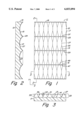
- FIG. 1 is a top view of a microlens array constructed in accordance with the invention.
- FIG. 2 is a cross-sectional view of the microlens array of FIG. 1 taken along the line 2--2 of FIG. 1.
- FIG. 3 is a cross-sectional view of the microlens array of FIG. 1 taken along the line 3--3 of FIG. 1.
- FIG. 4 is an enlarged top view of a portion of the microlens array of FIG. 1.
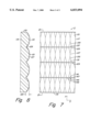
- FIG. 5 is a cross-sectional view of the microlens array of FIG. 4 taken along the line 5--5 of FIG. 4.
- FIG. 6 is a cross-sectional view of the lens array of FIG. 4 taken along the line 6--6 of FIG. 4.
- FIG. 7 is a top view of a second embodiment of a microlens array.
- FIG. 8 is a cross-sectional view of the microlens array of FIG. 7 taken along the line 8--8 of FIG. 7.
- Microlens array 11 has a substrate with appropriate optical properties and with a surface 13 on one side and a lens surface 15 on the opposite side. Surface 13 may be smooth but is preferably patterned.
- edges 17 are considered to be in a Y-direction and edges 19 are considered to be in an X-direction perpendicular to the Y-direction.
- the periphery of microlens array 11 may be of various shapes and need not be rectangular. Edges 17, 19 are shown for reference only.
- Lens surface 15 has a plurality of primary lenslets 21 which are arranged into a symmetrical array of Y-direction columns extending from one edge 19 to the other edge 19 and X-direction rows extending from one edge 17 to the other edge 17.
- primary lenslets 21 are formed in lens surface 15 at a first vertical extent or depth 23 in the substrate. They are shown in the drawing as being generally spherical or aspheric concave or negative lenses. In cross-section, as shown in FIGS. 2 and 3, primary lenslets 21 curve in both the X-direction and Y-direction. The depth and positions of the lenslets are calculated mathematically and graphically.
- each primary lenslet 21 has in projection a generally polygonal border or peripheral region 25.
- Primary lenslets 21 may have as few as four sides if secondary and tertiary lenslets are not present.
- peripheral region 25 is decagonal or ten-sided in shape and has a pair of Y-direction sides 27 and a pair of X-direction ends 29. Aside from the primary lenslets 21 located along Y-direction edges 17, each Y-direction side 27 adjoins a side 27 of an adjacent primary lenslet 21 in the same row. Similarly, other than the primary lenslets 21 located along X-direction edges 19, each X-direction end 29 adjoins an end 29 of an adjacent primary lenslet 21 in the same column.
- Lens surface 15 also has a plurality of secondary lenslets 31 which form part of the border region 25 of the primary lenslets 21.
- secondary lenslets 31 are formed in lens surface 15, but at a second depth 33 in the substrate (FIGS. 3 and 5). First depth 23 is deeper than second depth 33.
- each secondary lenslet 31 has a lesser surface area than each primary lenslet 21.
- Secondary lenslets 31 are generally negative spherical or aspheric lenses. In the cross-sectional views of FIGS. 5 and 6, secondary lenslets 31 curve in both the X-direction and Y-direction. Referring to FIGS. 1 and 4, each secondary lenslet 31 has a polygonal border or peripheral region 35.
- periphery 35 is generally in the shape of an isosceles triangle with a base 37 and sides 39.
- each base 37 is near a base 37 of an adjacent secondary lenslet 31.
- Each pair of adjacent secondary lenslets 31 extends partially between adjoining columns and rows of primary lenslets 21 so that peripheries 35 coincide with peripheries 25 along sides 39 (FIGS. 1 and 3).
- Microlens array 11 further comprises a symmetrical array of tertiary lenslets 41 which are selectively formed between primary lenslets 21 and secondary lenslets 31 into X-direction rows.
- Tertiary lenslets 41 are optional and could be located at various positions.
- Tertiary lenslets 41 share a periphery 25 with primary lenslets 21 as well as with secondary lenslets 31.
- Each tertiary lenslet 41 extends into lens surface 15 for a third depth 43 (FIGS. 3 and 6). Second depth 33 is deeper than third depth 43.
- each tertiary lenslet 41 has a lesser surface area than each secondary lenslet 31.
- Tertiary lenslets 41 have peripheries 45 which are hexagonal or six-sided in shape. Peripheries 45 have X-direction sides 47 and ends 49. Other than the tertiary lenslets 41 on edges 19, each side 47 coincides with a base 37 of a secondary lenslet 31. Each end 49 abuts another end 49.
- microlens array 111 has a substrate with appropriate optical properties and a surface 113 on one side and a lens surface 115 on the opposite side.
- Surface 113 may be smooth but is preferably patterned.
- edges 117 are considered to be in a Y-direction and edges 119 are considered to be in an X-direction perpendicular to the Y-direction.
- the periphery of microlens array 111 may be of various shapes and need not be rectangular. Edges 117, 119 are shown for reference only.
- Lens surface 115 has a plurality of primary lenslets 121 which are arranged into a symmetrical array of Y-direction columns extending from one edge 119 to the other edge 119 and X-direction rows extending from one edge 117 to the other edge 117.
- Primary lenslets 121 are formed in lens surface 115 at a first vertical dimension or elevation 123 in the substrate. They are shown in the drawing as being generally spherical or aspheric convex, or positive lenses. In cross-section, primary lenslets 121 curve in both the X-direction and Y-direction. The elevation and positions of the lenslets are calculated mathematically and graphically.
- Each primary lenslet 121 has in projection a generally polygonal border or peripheral region 125.
- Primary lenslets 121 may have as few as four sides if secondary and tertiary lenslets are not present.
- peripheral region 125 is decagonal or ten-sided in shape and has a pair of Y-direction sides 127 and a pair of X-direction ends 129. Aside from the primary lenslets 121 located along Y-direction edges 117, each Y-direction side 127 adjoins a side 127 of an adjacent primary lenslet 121 in the same row. Similarly, other than the primary lenslets 121 located along X-direction edges 119, each X-direction end 129 adjoins an end 129 of an adjacent primary lenslet 121 in the same column.
- Lens surface 115 also has a plurality of secondary lenslets 131 which form part of the border region 125 of the primary lenslets 121. Like primary lenslets 121, secondary lenslets 131 are formed in lens surface 115, but at a second elevation (not shown) in the substrate. First elevation 123 is deeper than the second elevation. Also, each secondary lenslet 131 has a lesser surface area than each primary lenslet 121. Secondary lenslets 131 are generally positive spherical or aspheric lenses. Secondary lenslets 131 curve in both the X-direction and Y-direction. Each secondary lenslet 131 has a polygonal border or peripheral region 135.
- periphery 135 is generally in the shape of an isosceles triangle with a base 137 and sides 139.
- each base 137 is near a base 137 of an adjacent secondary lenslet 131.
- Each pair of adjacent secondary lenslets 131 extends partially between adjoining columns and rows of primary lenslets 121 so that peripheries 135 coincide with peripheries 125 along sides 139.
- Microlens array 111 further comprises a symmetrical array of tertiary lenslets 141 which are selectively formed between primary lenslets 121 and secondary lenslets 131 into X-direction rows.
- Tertiary lenslets 141 are optional and could be located at various positions.
- Tertiary lenslets 141 share a periphery 125 with primary lenslets 121 as well as with secondary lenslets 131.
- Each tertiary lenslet 141 extends into lens surface 115 for a third elevation (not shown). The second elevation is deeper than the third elevation.
- each tertiary lenslet 141 has a lesser surface area than each secondary lenslet 131.
- Tertiary lenslets 141 have peripheries 145 which are hexagonal or six-sided in shape.
- Peripheries 145 have X-direction sides 147 and ends 149. Other than the tertiary lenslets 141 on edges 119, each side 147 coincides with a base 137 of a secondary lenslet 131. Each end 149 abuts another end 149.
- microlens arrays 11, 111 are utilized to provide desired illumination output patterns.
- One of microlens arrays 11, 111 is positioned between a light source (not shown) and a projection surface (not shown). When light from the light source is directed through microlens array 11 or 111 constructed as described above, a rectangular resultant beam pattern will be displayed on the projection surface.
- the invention has several advantages. Microlens arrays constructed with lenslets having multiple shapes at varying depths and/or elevations are adaptable to provide a variety of resultant beam pattern shapes.
- the improved microlens array also produces output beams with a higher intensity than those produced by etched or blasted surfaces.
Abstract
Description
Claims (8)
Priority Applications (1)
| Application Number | Priority Date | Filing Date | Title |
|---|---|---|---|
| US08/942,956 US6033094A (en) | 1997-10-02 | 1997-10-02 | Microlens array for improved illumination patterns |
Applications Claiming Priority (1)
| Application Number | Priority Date | Filing Date | Title |
|---|---|---|---|
| US08/942,956 US6033094A (en) | 1997-10-02 | 1997-10-02 | Microlens array for improved illumination patterns |
Publications (1)
| Publication Number | Publication Date |
|---|---|
| US6033094A true US6033094A (en) | 2000-03-07 |
Family
ID=25478878
Family Applications (1)
| Application Number | Title | Priority Date | Filing Date |
|---|---|---|---|
| US08/942,956 Expired - Lifetime US6033094A (en) | 1997-10-02 | 1997-10-02 | Microlens array for improved illumination patterns |
Country Status (1)
| Country | Link |
|---|---|
| US (1) | US6033094A (en) |
Cited By (16)
| Publication number | Priority date | Publication date | Assignee | Title |
|---|---|---|---|---|
| WO2001077716A2 (en) * | 2000-04-05 | 2001-10-18 | Rockwell Technologies, Llc | High fill-factor microlens array and fabrication method |
| US20030227685A1 (en) * | 2002-06-06 | 2003-12-11 | Nikon Corporation | Auxiliary light projection apparatus for auto focus detection |
| EP1398562A1 (en) * | 2002-09-11 | 2004-03-17 | ERCO Leuchten GmbH | Luminaire producing sharply delimited light cone |
| US20040130790A1 (en) * | 2002-09-20 | 2004-07-08 | Sales Tasso R. M. | Random microlens array for optical beam shaping and homogenization |
| US20040141241A1 (en) * | 2002-10-07 | 2004-07-22 | Fresnel Technologies Inc. | Imaging lens for infrared cameras |
| US6836365B2 (en) * | 1999-04-15 | 2004-12-28 | Nikon Corporation | Diffractive optical element, method of fabricating the element, illumination device provided with the element, projection exposure apparatus, exposure method, optical homogenizer, and method of fabricating the optical homogenizer |
| US20060203490A1 (en) * | 2005-03-10 | 2006-09-14 | Honeywell International Inc. | Luminaire with a one-sided diffuser |
| CN100378532C (en) * | 2004-09-01 | 2008-04-02 | 精工爱普生株式会社 | Method of manufacturing microlens, microlens, microlens array, electro-optical device, and electronic apparatus |
| US20080204731A1 (en) * | 2007-02-23 | 2008-08-28 | Williams Darin S | Optical device with tilt and power microlenses |
| US20090091837A1 (en) * | 2007-10-04 | 2009-04-09 | Industrial Technology Research Institute | Light guiding film |
| US20090142021A1 (en) * | 2007-12-03 | 2009-06-04 | Industrial Technology Research Institute | Composite light guiding film module |
| US20090154158A1 (en) * | 2007-12-14 | 2009-06-18 | Foxsemicon Integrated Technology, Inc. | Lamp cover and illumination lamp having same |
| US20090237943A1 (en) * | 2007-11-02 | 2009-09-24 | B/E Aerospace, Inc. | Flush mount reading light |
| US8460585B2 (en) | 2006-08-30 | 2013-06-11 | Industrial Technology Research Institute | Method of forming an optical diffusion module |
| US20160161083A1 (en) * | 2009-04-27 | 2016-06-09 | Enplas Corporation | Surface light source apparatus |
| US10033911B2 (en) | 2015-06-26 | 2018-07-24 | Cognex Corporation | Illumination assembly |
Citations (12)
| Publication number | Priority date | Publication date | Assignee | Title |
|---|---|---|---|---|
| US3163367A (en) * | 1959-08-10 | 1964-12-29 | Bodian Marcus | Light diffuser |
| US3330951A (en) * | 1965-05-17 | 1967-07-11 | Corning Glass Works | Diffusing lens for spotlights with axially oriented filaments |
| US3716710A (en) * | 1969-04-21 | 1973-02-13 | Trilux Lenze Gmbh & Co Kg | Lamp comprising an elongated light source,particularly a rod-shaped fluorescent lamp,and shade of transparent material |
| US3735124A (en) * | 1971-08-05 | 1973-05-22 | Emerson Electric Co | Prismatic lenses for lighting fixtures |
| US3764800A (en) * | 1972-10-17 | 1973-10-09 | Trilux Lenze Gmbh & Co Kg | Cover plate for a lamp |
| US3794829A (en) * | 1972-04-20 | 1974-02-26 | I Taltavull | Non-luminance lighting panel |
| US3829680A (en) * | 1972-11-24 | 1974-08-13 | Carroll J & Sons | Lighting panel |
| US4080529A (en) * | 1976-07-19 | 1978-03-21 | Dominion Auto Accessories Limited | Combination clearance and side marker lens |
| US4172273A (en) * | 1976-12-06 | 1979-10-23 | Patent-Treuhand-Gesellschaft Fur Elektrische Gluhlampen Mbh | Multiple flash unit with light-spreading protective shield |
| US4450509A (en) * | 1982-08-17 | 1984-05-22 | Thorn Emi Plc | Lanterns for area lighting |
| US5003448A (en) * | 1990-02-07 | 1991-03-26 | K-S-H, Inc. | Light-weight lenticular lighting panel |
| US5603561A (en) * | 1993-12-21 | 1997-02-18 | Koito Manufacturing Co., Ltd. | Vehicular lamp having appearance of depth |
-
1997
- 1997-10-02 US US08/942,956 patent/US6033094A/en not_active Expired - Lifetime
Patent Citations (12)
| Publication number | Priority date | Publication date | Assignee | Title |
|---|---|---|---|---|
| US3163367A (en) * | 1959-08-10 | 1964-12-29 | Bodian Marcus | Light diffuser |
| US3330951A (en) * | 1965-05-17 | 1967-07-11 | Corning Glass Works | Diffusing lens for spotlights with axially oriented filaments |
| US3716710A (en) * | 1969-04-21 | 1973-02-13 | Trilux Lenze Gmbh & Co Kg | Lamp comprising an elongated light source,particularly a rod-shaped fluorescent lamp,and shade of transparent material |
| US3735124A (en) * | 1971-08-05 | 1973-05-22 | Emerson Electric Co | Prismatic lenses for lighting fixtures |
| US3794829A (en) * | 1972-04-20 | 1974-02-26 | I Taltavull | Non-luminance lighting panel |
| US3764800A (en) * | 1972-10-17 | 1973-10-09 | Trilux Lenze Gmbh & Co Kg | Cover plate for a lamp |
| US3829680A (en) * | 1972-11-24 | 1974-08-13 | Carroll J & Sons | Lighting panel |
| US4080529A (en) * | 1976-07-19 | 1978-03-21 | Dominion Auto Accessories Limited | Combination clearance and side marker lens |
| US4172273A (en) * | 1976-12-06 | 1979-10-23 | Patent-Treuhand-Gesellschaft Fur Elektrische Gluhlampen Mbh | Multiple flash unit with light-spreading protective shield |
| US4450509A (en) * | 1982-08-17 | 1984-05-22 | Thorn Emi Plc | Lanterns for area lighting |
| US5003448A (en) * | 1990-02-07 | 1991-03-26 | K-S-H, Inc. | Light-weight lenticular lighting panel |
| US5603561A (en) * | 1993-12-21 | 1997-02-18 | Koito Manufacturing Co., Ltd. | Vehicular lamp having appearance of depth |
Cited By (34)
| Publication number | Priority date | Publication date | Assignee | Title |
|---|---|---|---|---|
| US6836365B2 (en) * | 1999-04-15 | 2004-12-28 | Nikon Corporation | Diffractive optical element, method of fabricating the element, illumination device provided with the element, projection exposure apparatus, exposure method, optical homogenizer, and method of fabricating the optical homogenizer |
| WO2001077716A3 (en) * | 2000-04-05 | 2002-05-02 | Rockwell Tech Llc | High fill-factor microlens array and fabrication method |
| WO2001077716A2 (en) * | 2000-04-05 | 2001-10-18 | Rockwell Technologies, Llc | High fill-factor microlens array and fabrication method |
| US20030227685A1 (en) * | 2002-06-06 | 2003-12-11 | Nikon Corporation | Auxiliary light projection apparatus for auto focus detection |
| US7012750B2 (en) * | 2002-06-06 | 2006-03-14 | Nikon Corporation | Auxiliary light projection apparatus for auto focus detection |
| EP1398562A1 (en) * | 2002-09-11 | 2004-03-17 | ERCO Leuchten GmbH | Luminaire producing sharply delimited light cone |
| US20040085771A1 (en) * | 2002-09-11 | 2004-05-06 | Erco Leuchten Gmbh | Lamp, especially for illuminating interiors |
| US7121693B2 (en) | 2002-09-11 | 2006-10-17 | Erco Leuchten Gmbh | Lamp, especially for illuminating interiors |
| US20040130790A1 (en) * | 2002-09-20 | 2004-07-08 | Sales Tasso R. M. | Random microlens array for optical beam shaping and homogenization |
| US6859326B2 (en) | 2002-09-20 | 2005-02-22 | Corning Incorporated | Random microlens array for optical beam shaping and homogenization |
| US20040141241A1 (en) * | 2002-10-07 | 2004-07-22 | Fresnel Technologies Inc. | Imaging lens for infrared cameras |
| US7474477B2 (en) | 2002-10-07 | 2009-01-06 | Fresnel Technologies, Inc. | Imaging lens for infrared cameras |
| US7187505B2 (en) | 2002-10-07 | 2007-03-06 | Fresnel Technologies, Inc. | Imaging lens for infrared cameras |
| US20070002467A1 (en) * | 2002-10-07 | 2007-01-04 | Fresnel Technologies Inc. | Imaging lens for infrared cameras |
| CN100378532C (en) * | 2004-09-01 | 2008-04-02 | 精工爱普生株式会社 | Method of manufacturing microlens, microlens, microlens array, electro-optical device, and electronic apparatus |
| US7690814B2 (en) | 2005-03-10 | 2010-04-06 | Honeywell International Inc. | Luminaire with a one-sided diffuser |
| WO2006098847A2 (en) * | 2005-03-10 | 2006-09-21 | Honeywell International Inc. | Luminaire with a one-sided diffuser |
| US20060203490A1 (en) * | 2005-03-10 | 2006-09-14 | Honeywell International Inc. | Luminaire with a one-sided diffuser |
| WO2006098847A3 (en) * | 2005-03-10 | 2007-04-26 | Honeywell Int Inc | Luminaire with a one-sided diffuser |
| US8460585B2 (en) | 2006-08-30 | 2013-06-11 | Industrial Technology Research Institute | Method of forming an optical diffusion module |
| US20080204731A1 (en) * | 2007-02-23 | 2008-08-28 | Williams Darin S | Optical device with tilt and power microlenses |
| US7762683B2 (en) * | 2007-02-23 | 2010-07-27 | Raytheon Company | Optical device with tilt and power microlenses |
| US20090091837A1 (en) * | 2007-10-04 | 2009-04-09 | Industrial Technology Research Institute | Light guiding film |
| US7911700B2 (en) * | 2007-10-04 | 2011-03-22 | Industrial Technology Research Institute | Light guiding film |
| US20090237943A1 (en) * | 2007-11-02 | 2009-09-24 | B/E Aerospace, Inc. | Flush mount reading light |
| US7711223B2 (en) * | 2007-12-03 | 2010-05-04 | Industrial Technology Research Institute | Composite light guiding film module |
| US20090142021A1 (en) * | 2007-12-03 | 2009-06-04 | Industrial Technology Research Institute | Composite light guiding film module |
| US20090154158A1 (en) * | 2007-12-14 | 2009-06-18 | Foxsemicon Integrated Technology, Inc. | Lamp cover and illumination lamp having same |
| US7794117B2 (en) * | 2007-12-14 | 2010-09-14 | Foxsemicon Integrated Technology, Inc. | Lamp cover and illumination lamp having same |
| US20160161083A1 (en) * | 2009-04-27 | 2016-06-09 | Enplas Corporation | Surface light source apparatus |
| US9546773B2 (en) * | 2009-04-27 | 2017-01-17 | Enplas Corporation | Surface light source apparatus |
| US20170089543A1 (en) * | 2009-04-27 | 2017-03-30 | Enplas Corporation | Method of manufacturing light flux controlling member |
| US9752750B2 (en) * | 2009-04-27 | 2017-09-05 | Enplas Corporation | Method of manufacturing light flux controlling member |
| US10033911B2 (en) | 2015-06-26 | 2018-07-24 | Cognex Corporation | Illumination assembly |
Similar Documents
| Publication | Publication Date | Title |
|---|---|---|
| US6033094A (en) | Microlens array for improved illumination patterns | |
| KR200364045Y1 (en) | A brightness enhancement film having curved prism units | |
| US7712932B2 (en) | Light redirecting films having optical elements with curved surfaces | |
| JP5006914B2 (en) | Light guide plate | |
| US6759113B1 (en) | Uniform curved surface structure of a brightness unit for a brightness enhancement film | |
| US7085062B2 (en) | Apparatus for shaping a light beam | |
| US20040130790A1 (en) | Random microlens array for optical beam shaping and homogenization | |
| US9146016B2 (en) | Tiling of multiple polygons for micro-lens array | |
| US20160018077A1 (en) | Led luminaire | |
| WO1999050596A2 (en) | Illumination device for generating non-symmetric light beam, optical lens array and optical lens | |
| JP2002538577A5 (en) | ||
| US20090296222A1 (en) | Device for Homogenizing Light | |
| CN104456418A (en) | Faceted LED street lamp lens | |
| KR20120024320A (en) | Optical lens, light source module and street lamp having the same | |
| GB1592707A (en) | Shadowless lighting appliance | |
| TWI537609B (en) | Thinner type lens | |
| US8851710B2 (en) | Lighting device | |
| WO2011143015A1 (en) | Optical beam shaping devices using microfacets | |
| TW200607199A (en) | Lens-attached light-emitting element | |
| TW201335629A (en) | Non-imaging optical lens and lighting device with the lens | |
| US6950234B1 (en) | Protective film for a prism lens | |
| JP2023159281A5 (en) | ||
| CA2403569A1 (en) | Optical instrument and optical element providing expanded exit pupil | |
| US10942297B2 (en) | Optical output device and design method | |
| US9217554B1 (en) | Optical element providing oblique illumination and apparatuses using same |
Legal Events
| Date | Code | Title | Description |
|---|---|---|---|
| AS | Assignment |
Owner name: FRESNEL TECHNOLOGIES, INC., TEXAS Free format text: ASSIGNMENT OF ASSIGNORS INTEREST;ASSIGNOR:SOHN, ALEXANDER;REEL/FRAME:008837/0475 Effective date: 19970923 |
|
| STCF | Information on status: patent grant |
Free format text: PATENTED CASE |
|
| FEPP | Fee payment procedure |
Free format text: PAYOR NUMBER ASSIGNED (ORIGINAL EVENT CODE: ASPN); ENTITY STATUS OF PATENT OWNER: SMALL ENTITY |
|
| FPAY | Fee payment |
Year of fee payment: 4 |
|
| FEPP | Fee payment procedure |
Free format text: PAYER NUMBER DE-ASSIGNED (ORIGINAL EVENT CODE: RMPN); ENTITY STATUS OF PATENT OWNER: SMALL ENTITY |
|
| FPAY | Fee payment |
Year of fee payment: 8 |
|
| REMI | Maintenance fee reminder mailed | ||
| FEPP | Fee payment procedure |
Free format text: PAYOR NUMBER ASSIGNED (ORIGINAL EVENT CODE: ASPN); ENTITY STATUS OF PATENT OWNER: SMALL ENTITY |
|
| FPAY | Fee payment |
Year of fee payment: 12 |