US6032854A - Multiple-use sealable packages - Google Patents
Multiple-use sealable packages Download PDFInfo
- Publication number
- US6032854A US6032854A US09/035,007 US3500798A US6032854A US 6032854 A US6032854 A US 6032854A US 3500798 A US3500798 A US 3500798A US 6032854 A US6032854 A US 6032854A
- Authority
- US
- United States
- Prior art keywords
- closure flap
- line
- closure
- adhesive
- mouth opening
- Prior art date
- Legal status (The legal status is an assumption and is not a legal conclusion. Google has not performed a legal analysis and makes no representation as to the accuracy of the status listed.)
- Expired - Lifetime
Links
Images


Classifications
-
- B—PERFORMING OPERATIONS; TRANSPORTING
- B65—CONVEYING; PACKING; STORING; HANDLING THIN OR FILAMENTARY MATERIAL
- B65D—CONTAINERS FOR STORAGE OR TRANSPORT OF ARTICLES OR MATERIALS, e.g. BAGS, BARRELS, BOTTLES, BOXES, CANS, CARTONS, CRATES, DRUMS, JARS, TANKS, HOPPERS, FORWARDING CONTAINERS; ACCESSORIES, CLOSURES, OR FITTINGS THEREFOR; PACKAGING ELEMENTS; PACKAGES
- B65D27/00—Envelopes or like essentially-rectangular containers for postal or other purposes having no structural provision for thickness of contents
- B65D27/06—Envelopes or like essentially-rectangular containers for postal or other purposes having no structural provision for thickness of contents with provisions for repeated re-use
Definitions
- Spunbonded olefin sheet material is very desirable packaging material for numerous uses, including envelopes, (flat or expansion) pouches, folders, sleeves, etc.
- Spunbonded olefin sheet material is relatively light for its strength in comparison to paper and other, conventional packaging materials.
- One reason it is good for packaging is its strength.
- paper weighing two to three times as much as spunbonded olefin sheet is required to provide comparable strength.
- Spunbonded olefin sheet has other characteristics making it desirable for packaging.
- the dense fiber network forming the sheet material offers extremely high resistance to tear, puncture and abrasion.
- Spunbonded olefin sheet material has excellent resistance to waterborne soil and good resistance to degradation from age unless overly exposed to ultraviolet light. It is inert to most acids, unaffected by water or highly polar solvents and is therefore readily washable. It further meets the requirements of the Federal Flame Fabrics Act.
- Spunbonded olefin sheet is sold in different forms which have different characteristics in terms of tear strengths, tensile strengths, smoothness, porosity, flexibility and softness.
- Either cold applied adhesives such as polyvinyl acetate resin (PVA) or hot-melt pressure sensitive adhesive (PSA) are typically used with spunbonded olefin material in packaging. Such adhesives are very tenacious and stick firmly to the generally smooth and non-porous olefin sheet.
- Hot-melt adhesive can be applied during package fabrication to the closure flap as a pressure-sensitive adhesive closure with a release material liner protecting the closure until it is time to seal the mouth of the package.
- the invention is a multiple-use, sealable package comprising a body of spunbonded olefin sheet, the body having at least one side edge with a mouth opening; a closure flap of spunbonded olefin sheet extending from the body at the side edge along the mouth opening, the closure flap having an inner surface facing and overlapping an edge portion of the body adjoining the mouth opening with the closure flap folded and fully extended over the mouth opening and against the body to close the mouth opening; two separate and spaced apart adhesive closures, each adhesive closure being located on the spunbonded olefin sheet proximal the mouth opening, one adhesive closure being located farther from the mouth opening than is a remaining adhesive closure; a line of openings extending through and across the closure flap, the openings being spaced sufficiently closely to one another along the line that a tear force required to break bridges of the spunbonded olefin sheet of the closure flap between adjoining pairs of the openings of the line is less than a tear force required to separate one of the adhesive closures from the spunbonded olef
- the invention is a multiple-use, sealable flat envelope comprising a body of spunbonded olefin sheet having two flat, juxtaposed panels, one side edge with a mouth opening and three remaining, permanently closed side edges; a spunbonded olefin sheet closure flap extending continuously in one piece from one of the panels of the body along at the one side edge of the body, the closure flap having an inner surface facing and overlapping an edge portion of a remaining panel of the body adjoining the mouth opening when the closure flap is folded back towards the body and fully extended over the mouth opening against the remaining panel of the body to close the mouth opening; two adjoining but separate and spaced apart hot melt, pressure sensitive adhesive closures on the spunbonded olefin sheet of the inner surface of the closure flap; a line of openings through the closure flap extending entirely across the closure flap, the openings being spaced sufficiently closely to one another along the line that a tear force required to break bridges of the spunbonded olefin sheet of the closure flap between adjoining pairs of the openings of the line
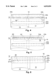
- FIG. 1 is a plan view of one side of a multiple use, resealable package of the present invention in the form of an envelope in an open configuration;
- FIG. 2 is a cut-away plan view of the mouth opening end of the package of FIG. 1 after removal of half of the release liner and before sealing of the package;
- FIG. 3 is a cut-away plan view of the mouth opening end of the package of FIGS. 1 and 2 after first closure and sealing of the package;
- FIG. 4 is a cut-away plan view of the mouth opening end of the package of FIGS. 1-3 after opening of the sealed closure flap;
- FIG. 5 is a cut-away plan view of the mouth opening end of the package of FIGS. 1-4 after the second half of the release liner is removed from the package;
- FIG. 6 is a cut-away plan view of the mouth opening end of the package of FIGS. 1-5 after the second closure of the flap.
- the envelope 10 is formed from one continuous piece of spunbonded olefin sheet, which is folded and bonded together in a conventional fashion to form a normally flat body indicated generally at 12.
- the normally flat body 12 has a pair of adjoining and opposing major sides defined by panels 13 and 14. At least one side edge of the body 12 has a mouth opening 15. Preferably, each of the remaining three side edges of the body 12 are permanently closed.
- a closure flap 20 of spunbonded olefin sheet extends from the body 12 at the side edge along the mouth opening 15.
- the closure flap 20 has an inner surface 22 seen in FIGS. 1, 2, 4 and 5 and an opposing outer surface 23 seen in FIGS. 3 and 6.
- the inner surface 22 faces and overlaps an edge portion 13a of panel 13 of the body 12 proximal the mouth opening 15 when the closure flap 20 is folded back toward the body and fully extended over the mouth opening 15 and against panel 13 of the body 12 to close the mouth opening 15 as indicated in FIG. 3.
- the closure flap 20 is merely a continuous extension of the panel 14 of the body 12 beyond the adjoining edge of panel 13 at the mouth opening 15 and beyond a fold line 20', which is tangent to the side edges of panel 13 where it joins panel 14 at the mouth opening edge of the envelope body 12.
- the edge portion 13a is bounded on one side by the mouth opening 15 and is identified by broken line 13a'.
- two adjoining but separate and spaced apart adhesive closure 24a, 24b are provided, on the spunbonded olefin sheet near (proximal) the mouth opening 15.
- both are located on the inner surface 22 of the closure flap 20 as shown in FIGS. 1 and 2.
- the two adhesive closures could have been located in the edge portion 13a of the body 12 overlapped by the closure flap 20 or one located in the edge portion and one located on the closure flap. (Neither of the latter two engagements is depicted.)
- one closure 24a is located farther or more remotely (“distally") from mouth opening 15 and fold line 20' in either the open position of closure flap 20 (seen in FIGS. 1, 2, 4 and 5) or the closed position of flap 20 (seen in FIGS. 3 and 6) than is the second, remaining, "proximal" closure 24b.
- a line of openings 26 through closure flap 20 extends across the closure flap 20, preferably from one side edge to an opposing side edge of the closure flap 20.
- the openings 26 divide the flap 20 into a first or distal portion 20a and a remaining or proximal portion 20b.
- the openings 26 are spaced sufficiently closely to one another along the line that the tear force required to break bridges 28 of the spunbonded olefin sheet of the closure flap 20 between adjoining pairs of the openings 26 of the line is less than a tear force required to separate the one of the adhesive closures 24a, 24b from the closure flap 20 (or the edge portion 13a of the body 12 once the envelope 10 is sealed with adhesive closure 24a).
- the spaced apart adhesive closures 24a and 24b are located on the closure flap 20 on opposite sides of the line of openings 26 extending across that flap. If the adhesive closures were to have been applied to the edge portion 13a of the body 12, they would also be spaced apart and located so as to be on either side of the line of openings 26 when the closure flap 20 with the closure flap folded back over line 20' and fully extended over the mouth opening 15, fully overlapping the edge portion 13a and closing the mouth opening 15 as indicated in FIG. 3. Openings 26 are preferably slits cut through the spunbonded olefin sheet forming flap 20.
- a separate release liner 30 is provided on the inner surface 22 of closure flap 20 simultaneously covering the two adhesive closures 24a, 24b for protecting the adhesive closures before use.
- the release liner 30 is also divided into two parts 30a, 30b by at least one line of weakness 32, which extends across the release liner 30.
- the line of weakness 32 is provided by the line of perforations through the release liner 30, but may also be provided in other conventional forms, depending upon the composition of the release liner (e.g., paper, plastic, foil, composite, etc.).
- the at least one line of weakness 32 extending across the release liner 30 is located on the package 10 to lie between the two adhesive closures 24a, 24b and to be closer to the open mouth 15 of the package 10 than is the line of openings 26 through the closure flap 20. If the adhesive closure 24a, 24b and release liner 30 were located on panel 13 of the body 12, then the line of weakness 32 would still be positioned on the package 10 so as to be located closer to the mouth opening 15 than is the line of openings 26 through the closure flap 20.
- Closure flap 20 is further suggestedly provided with at least one and preferably two notches 27a, 27b, each of which extends into one of the opposing edges of the closure flap 20 at opposing ends of the line of openings 26 through the closure flap.
- Each notch 27a, 27b defines an opening along the edge of the closure flap larger in area than the areas of any of the openings 26 adjoining either notch 27a, 27b.
- the area of the notch 27a or 27b is the open area within tangent line 29a or 29b to the side edge of the closure flap on either side of the line of openings 26.
- the part of panel 13 of the body 12 overlaid by the proximal end 20b of the closure flap 20 and the proximate adhesive closure 24b can be provided with a breakaway region indicated generally at 16 and preferably defined by a continuous line of openings 17 through the body 12 proximal to the mouth opening 15.
- the breakaway region 16 is located such that at least part of the proximal or "remaining" adhesive closure 24b overlaps at least part of the breakaway region 16 when the closure flap 20 is folded back along fold line 20' and fully extended over the edge portion 13a of the body 12 to close the mouth opening 15.
- the breakaway region 16, overlapped by the proximal adhesive closure 24b, is subject to tear forces applied to the package 10 to separate the remainder 20b of the closure flap 20 from the adjoining panel 13 when the package is opened after the closure flap 20 is sealed for the second time with the proximal adhesive closure 24b.
- the continuous line of openings 17 defines all but a final side (typically at least three sides) of the breakaway region 16 with the final side (typically a fourth side) defined by the edge of panel 13 at mouth opening 15.
- the openings 17 in the body 12 are also spaced just sufficiently closely to one another along the line that a tear force required to break bridges 18 of the spunbonded olefin sheet forming the panel 13, which are left between adjoining pairs of the openings 17 of the line, is less than the tear force required to separate either the remainder 20b of the closure flap 20 or the breakaway region 16 from the remaining adhesive closure 24b. Further detail about the provision of such breakaway regions can be found in U.S. Pat. No. 5,499,757, incorporated by reference herein in its entirety.
- the openings of line 17 are also preferably perforations formed by cut slits through the spunbonded olefin sheet.
- the invention is suitable for use in other types of spunbonded olefin sheet packaging.
- both adhesive closures and the single release liner be applied to the envelope closure flap
- the two adhesive closures and the single release liner could, less desirably, be applied to the body of the envelope or other package and, least desirably, could be split between the body and the closure flap. That is, one adhesive closure with a release liner would be located on the body and one with separate release liner located on the flap.
- the far or outer or “distal" edge of the release liner overlying the adhesive closure 24b located closest to the mouth opening 15 of the package would also be located closer to the mouth opening 15 than would the line of perforation through the closure flap. While hot-melt, pressure sensitive adhesives are preferred for the flap, other adhesives such as cold applied PVA resin might be used as might still other bonding agents on the flaps and/or on seams of the envelope.
- envelope 10 is conventional quite similar to the fabrication of single use, sealable, spunbonded olefin sheet envelopes with the additional provision of the line of openings 26 and notches 27a and 27b in the closure flap 20, two adhesive closures 24a, 24b instead of one and a line of weakness 32 in release liner 30.
- the particular spunbonded olefin material selected should depend upon the intended use of the package.
- a conventional, flat envelope like envelope 10 described above might use a Type 1056/D or 1070/D or other grade weight of Tyvek® material, manufactured by E. I. Dupont & Company of Wilmington, Del.
- the hot-melt, pressure sensitive adhesive which could be used on both the permanently sealed seams and the closure flap, might be, for example, adhesive no.
- the release liner might be, for example, stock 25 to 30 ksia of Tekkote of Leonia, N.J., which are 25 to 30 lb. weight paper bases having a silicone treatment on only one side.
- the openings 26 through the flap might be cut slits spaced 1/8 inch apart and ranging from 1/64 to 1/16 inch in length.
- Envelope 10 preferably is formed from a continuous, one piece blank of spunbonded olefin sheet.
- Panel 14 (which supports closure flap 20) is seamless and unbroken while the remaining panel 13 is formed by folding over two side flaps (on either side of the closure flap) and a bottom flap (opposite the closure flap) in a conventional fashion, again preferably utilizing a hot-melt adhesive to permanently seal the mutually overlying flaps.
- the hot-melt, pressure sensitive adhesive is extruded in two separate and spaced apart lines on the silicone treated side of a continuous length of the release liner web with gaps along the extended lines.
- the gaps are positioned or located to define the areas along the continuous length where it is cut to form an individual release liner to be applied as noted above to a single envelope.
- each adhesive closure 24a, 24b is indented somewhat from the side edges of the closure flap 20, (those edges between which the line of openings 26 extends), so as to provide a free side edge portion of the closure flap 20 which can be gripped to tear the closure flap along the line of openings 26 to open the envelope 10 after it has been sealed a first time.
- the continuous length web of release material is cut to an individual envelope length and applied to the flap 20 with the adhesive facing the flap inner surface 22.
- the outer (distal) part 30a of the release liner 30 extends even with or somewhat recessed from the outermost edge of the closure flap 20 to prevent the release liner 30 from being accidentally grabbed and/or disrupted before the envelope is sealed.
- the outer (distal) edge of release liner 30 can extend beyond the outer edge of closure flap 20 to enable the distal half 30a of the release liner to be easily gripped to separate that part 30a from the remaining part 30b of the release liner 30, which is located more proximal to the mouth opening 15.
- Envelope 10 preferably is used in the manner indicated in FIGS. 1 through 6.
- the closure flap 20 is initially unfolded or folded away from the body 12 of the envelope 10 to expose the mouth opening 15 for insertion of contents into the envelope 10.
- a distal part 30a of the release liner 30 is removed to expose the first or distal adhesive closure 24a and, leaving only the proximal part 30b over the remaining, more proximally located adhesive closure 24b.
- the closure flap 20 is then folded back towards the body 12 generally along the fold line 20', which is tangent to the two edges of the envelope 10 at either lateral side of the closure flap 20, and is fully extended over the mouth opening 15 and pressed against the body 12 as shown in FIG. 3 to close mouth opening 15.
- the once closed envelope 10 shown in FIG. 3 is opened by pulling the remaining or proximal portion 20b of the closure flap from the first portion 20a, which is adhered to envelope body 10, until the closure flap 20 parts along line of openings 26 or cutting the flap 20 preferably through or along the line of openings 26.
- the proximal part 30b of the release liner 30 is shown in phantom in FIG. 3.
- the lateral edges of the release liner 30 preferably are recessed away from the lateral edges of the closure flap 20 while the outer or remote or distal edge of that remaining part 30b of the release liner 30 is recessed from the line of openings 26 through the closure flap 20 so that when the closure flap 20 is torn along the line of openings 26, the proximal part 30b of the release liner 30 is not in a position to be contacted or pulled away from the remaining adhesive closure 24b. This is to prevent inadvertent exposure and adhesion of that closure 24b to the envelope 10 before its intended second use.
- the outer edge of part 30b of the release liner 30 is recessed at least 1/16 inch and more desirably at least 1/8 inch and most preferably at least 3/16 inch from the line of openings 26.
- the closure flap 20 is again folded away from the body 12 to expose the mouth opening 15 to receive the contents of the envelope 10.
- the remaining portion 30b of the release liner 30 is removed and the remaining portion 20b of the closure flap 20 is again fully extended over the mouth opening 15 and pressed against the body 13 to close and seal the mouth opening 15.
- the sealed envelope could be open in a conventional fashion a second time by physically separating either the remainder 20b of the closure flap 20 or the panel 13 from the adhesive closure 24b.
- a breakaway region 16 it would be torn from the remainder of panel 14 along line of openings 17.
Abstract
Description
Claims (10)
Priority Applications (1)
| Application Number | Priority Date | Filing Date | Title |
|---|---|---|---|
| US09/035,007 US6032854A (en) | 1998-03-05 | 1998-03-05 | Multiple-use sealable packages |
Applications Claiming Priority (1)
| Application Number | Priority Date | Filing Date | Title |
|---|---|---|---|
| US09/035,007 US6032854A (en) | 1998-03-05 | 1998-03-05 | Multiple-use sealable packages |
Publications (1)
| Publication Number | Publication Date |
|---|---|
| US6032854A true US6032854A (en) | 2000-03-07 |
Family
ID=21880058
Family Applications (1)
| Application Number | Title | Priority Date | Filing Date |
|---|---|---|---|
| US09/035,007 Expired - Lifetime US6032854A (en) | 1998-03-05 | 1998-03-05 | Multiple-use sealable packages |
Country Status (1)
| Country | Link |
|---|---|
| US (1) | US6032854A (en) |
Cited By (20)
| Publication number | Priority date | Publication date | Assignee | Title |
|---|---|---|---|---|
| US6299355B1 (en) * | 1998-12-07 | 2001-10-09 | Gene Douglas Schneck | Recloseable easy-open industrial bag and tab for use therewith |
| US6699541B2 (en) | 2001-02-12 | 2004-03-02 | Arnold Finestone | Self-closing adhesive-free resealable package |
| US6723408B2 (en) | 2002-05-07 | 2004-04-20 | A.D.M. Corporation | Resealable envelope |
| US6725587B2 (en) | 2001-06-27 | 2004-04-27 | Winkler & Dunnebrier, Ag | Combination envelope and greeting card |
| US20040079667A1 (en) * | 2002-09-10 | 2004-04-29 | Joel Bartholf | Shipping device and method for articles capable of releasing gas containing hazardous particulates |
| US20040197504A1 (en) * | 1994-10-24 | 2004-10-07 | Finestone Arnold B. | Laminate sheeting for pouches |
| US6805348B1 (en) * | 2003-06-02 | 2004-10-19 | Samuel Chen | Baseball board game |
| US20050072694A1 (en) * | 2003-10-07 | 2005-04-07 | Gamefly, Inc. | System and apparatus for protecting digital media |
| US20060043159A1 (en) * | 2004-08-13 | 2006-03-02 | Cryovac, Inc. | Return mailer |
| US20060251464A1 (en) * | 2005-05-09 | 2006-11-09 | Bauer Walter G | Device with pull tab activation |
| US20060285783A1 (en) * | 2006-06-01 | 2006-12-21 | Burnett John A Jr | Fluorescent buld disposal bag |
| US20070134048A1 (en) * | 2005-12-13 | 2007-06-14 | Bauer Walter G | Device with internal pull tab activation |
| US20070147942A1 (en) * | 2005-12-14 | 2007-06-28 | Sojka Marci E | Water-dispersible device with pull tab activation |
| US7350689B1 (en) | 2004-12-17 | 2008-04-01 | The United States Of America As Represented By The National Security Agency | Reusable tamper evident envelope |
| US20110068161A1 (en) * | 2004-09-09 | 2011-03-24 | Dan Perrone | Two way electronic media mailer |
| US9302821B2 (en) | 2012-05-15 | 2016-04-05 | Automated Packaging Systems | Reclosable bag and methods of forming and using same |
| USD780843S1 (en) * | 2015-05-13 | 2017-03-07 | Chief Of Internet Sweden Ab | Envelope for transport cover |
| US20180305104A1 (en) * | 2017-04-19 | 2018-10-25 | Shanghai Sannian Environmental Protection Technology Company Limited | Easy-to-open Packaging Bag |
| US11117711B2 (en) * | 2019-09-20 | 2021-09-14 | J.B. Machines S.r.l. | Bag made of paper material for archiving articles and method for archiving an article in said bag |
| WO2022023093A1 (en) * | 2020-07-30 | 2022-02-03 | Holweg Group | Reusable envelope with pre-cut closure flap, method and machine for manufacturing such an envelope |
Citations (16)
| Publication number | Priority date | Publication date | Assignee | Title |
|---|---|---|---|---|
| US192522A (en) * | 1877-06-26 | Improvement in envelopes | ||
| US1091172A (en) * | 1911-05-12 | 1914-03-24 | Walter Thayer | Return-envelop. |
| US1553028A (en) * | 1924-01-04 | 1925-09-08 | Ward L Bumgardner | Return envelope |
| US3946938A (en) * | 1974-09-18 | 1976-03-30 | Tension Envelope Corporation | Two piece mailer |
| DE2647357A1 (en) * | 1975-10-24 | 1977-04-28 | Soeren Elof Mauritz Sollerud | ENVELOPE OR ENVELOPE BAG |
| US4807805A (en) * | 1987-01-20 | 1989-02-28 | Avery International Corporation | Dual envelope sheet-fed assembly |
| US5025980A (en) * | 1990-07-13 | 1991-06-25 | Federal Paper Board Co., Inc. | Double use express mail envelope |
| US5044776A (en) * | 1990-04-27 | 1991-09-03 | Morgan Adhesives Company | Resealable closure system |
| CH680124A5 (en) * | 1990-03-22 | 1992-06-30 | Brieger Verpackungen Ag | Cardboard dispatch envelope with tear=off sealing flap - which has perforating line space from edge and extending over flap entire width |
| US5213258A (en) * | 1991-05-03 | 1993-05-25 | Kim Myun H | Resealable, returnable envelope |
| AU642123B3 (en) * | 1991-01-09 | 1993-10-07 | Jeffrey Allan Jones | Improvements in and relating to envelopes |
| WO1993019991A2 (en) * | 1992-04-01 | 1993-10-14 | Ahmet Mehmet Husnu | Re-usable envelopes |
| US5400957A (en) * | 1992-04-23 | 1995-03-28 | Stude; Michael | Reusable envelope |
| US5415341A (en) * | 1992-05-21 | 1995-05-16 | Diamond Gamma, L.L.C. | Business envelope |
| US5499757A (en) * | 1994-04-25 | 1996-03-19 | International Envelope Company | Easy open, tamper evident envelope |
| US5503328A (en) * | 1993-05-13 | 1996-04-02 | Waldorf Corporation | Multi-use envelope |
-
1998
- 1998-03-05 US US09/035,007 patent/US6032854A/en not_active Expired - Lifetime
Patent Citations (16)
| Publication number | Priority date | Publication date | Assignee | Title |
|---|---|---|---|---|
| US192522A (en) * | 1877-06-26 | Improvement in envelopes | ||
| US1091172A (en) * | 1911-05-12 | 1914-03-24 | Walter Thayer | Return-envelop. |
| US1553028A (en) * | 1924-01-04 | 1925-09-08 | Ward L Bumgardner | Return envelope |
| US3946938A (en) * | 1974-09-18 | 1976-03-30 | Tension Envelope Corporation | Two piece mailer |
| DE2647357A1 (en) * | 1975-10-24 | 1977-04-28 | Soeren Elof Mauritz Sollerud | ENVELOPE OR ENVELOPE BAG |
| US4807805A (en) * | 1987-01-20 | 1989-02-28 | Avery International Corporation | Dual envelope sheet-fed assembly |
| CH680124A5 (en) * | 1990-03-22 | 1992-06-30 | Brieger Verpackungen Ag | Cardboard dispatch envelope with tear=off sealing flap - which has perforating line space from edge and extending over flap entire width |
| US5044776A (en) * | 1990-04-27 | 1991-09-03 | Morgan Adhesives Company | Resealable closure system |
| US5025980A (en) * | 1990-07-13 | 1991-06-25 | Federal Paper Board Co., Inc. | Double use express mail envelope |
| AU642123B3 (en) * | 1991-01-09 | 1993-10-07 | Jeffrey Allan Jones | Improvements in and relating to envelopes |
| US5213258A (en) * | 1991-05-03 | 1993-05-25 | Kim Myun H | Resealable, returnable envelope |
| WO1993019991A2 (en) * | 1992-04-01 | 1993-10-14 | Ahmet Mehmet Husnu | Re-usable envelopes |
| US5400957A (en) * | 1992-04-23 | 1995-03-28 | Stude; Michael | Reusable envelope |
| US5415341A (en) * | 1992-05-21 | 1995-05-16 | Diamond Gamma, L.L.C. | Business envelope |
| US5503328A (en) * | 1993-05-13 | 1996-04-02 | Waldorf Corporation | Multi-use envelope |
| US5499757A (en) * | 1994-04-25 | 1996-03-19 | International Envelope Company | Easy open, tamper evident envelope |
Cited By (27)
| Publication number | Priority date | Publication date | Assignee | Title |
|---|---|---|---|---|
| US20040197504A1 (en) * | 1994-10-24 | 2004-10-07 | Finestone Arnold B. | Laminate sheeting for pouches |
| US6299355B1 (en) * | 1998-12-07 | 2001-10-09 | Gene Douglas Schneck | Recloseable easy-open industrial bag and tab for use therewith |
| US6699541B2 (en) | 2001-02-12 | 2004-03-02 | Arnold Finestone | Self-closing adhesive-free resealable package |
| US20040209024A1 (en) * | 2001-02-12 | 2004-10-21 | Arnold Finestone | Cushioning self-closing packaging material |
| US6725587B2 (en) | 2001-06-27 | 2004-04-27 | Winkler & Dunnebrier, Ag | Combination envelope and greeting card |
| US6723408B2 (en) | 2002-05-07 | 2004-04-20 | A.D.M. Corporation | Resealable envelope |
| US7191579B2 (en) * | 2002-09-10 | 2007-03-20 | Joel Bartholf | Shipping device and method for articles capable of releasing gas containing hazardous particulates |
| US20040079667A1 (en) * | 2002-09-10 | 2004-04-29 | Joel Bartholf | Shipping device and method for articles capable of releasing gas containing hazardous particulates |
| US6805348B1 (en) * | 2003-06-02 | 2004-10-19 | Samuel Chen | Baseball board game |
| US20050072694A1 (en) * | 2003-10-07 | 2005-04-07 | Gamefly, Inc. | System and apparatus for protecting digital media |
| US6951279B2 (en) * | 2003-10-07 | 2005-10-04 | Gamefly, Inc. | System and apparatus for protecting digital media |
| US20060043159A1 (en) * | 2004-08-13 | 2006-03-02 | Cryovac, Inc. | Return mailer |
| US20110068161A1 (en) * | 2004-09-09 | 2011-03-24 | Dan Perrone | Two way electronic media mailer |
| US8701978B2 (en) | 2004-09-09 | 2014-04-22 | R.R. Donnelley & Sons Company | Two way electronic media mailer |
| US7350689B1 (en) | 2004-12-17 | 2008-04-01 | The United States Of America As Represented By The National Security Agency | Reusable tamper evident envelope |
| US7651290B2 (en) | 2005-05-09 | 2010-01-26 | Kimberly-Clark Worldwide, Inc. | Device with pull tab activation |
| US20060251464A1 (en) * | 2005-05-09 | 2006-11-09 | Bauer Walter G | Device with pull tab activation |
| US7950864B2 (en) | 2005-12-13 | 2011-05-31 | Kimberly-Clark Worldwide, Inc. | Device with internal pull tab activation |
| US20070134048A1 (en) * | 2005-12-13 | 2007-06-14 | Bauer Walter G | Device with internal pull tab activation |
| US20070147942A1 (en) * | 2005-12-14 | 2007-06-28 | Sojka Marci E | Water-dispersible device with pull tab activation |
| US20060285783A1 (en) * | 2006-06-01 | 2006-12-21 | Burnett John A Jr | Fluorescent buld disposal bag |
| US9302821B2 (en) | 2012-05-15 | 2016-04-05 | Automated Packaging Systems | Reclosable bag and methods of forming and using same |
| USD780843S1 (en) * | 2015-05-13 | 2017-03-07 | Chief Of Internet Sweden Ab | Envelope for transport cover |
| US20180305104A1 (en) * | 2017-04-19 | 2018-10-25 | Shanghai Sannian Environmental Protection Technology Company Limited | Easy-to-open Packaging Bag |
| US11117711B2 (en) * | 2019-09-20 | 2021-09-14 | J.B. Machines S.r.l. | Bag made of paper material for archiving articles and method for archiving an article in said bag |
| WO2022023093A1 (en) * | 2020-07-30 | 2022-02-03 | Holweg Group | Reusable envelope with pre-cut closure flap, method and machine for manufacturing such an envelope |
| FR3113036A1 (en) * | 2020-07-30 | 2022-02-04 | Holweg Group | Reusable envelope with pre-cut closure flap, method and machine for manufacturing such an envelope |
Similar Documents
| Publication | Publication Date | Title |
|---|---|---|
| US6032854A (en) | Multiple-use sealable packages | |
| US4468811A (en) | Tamper-evident closure for bag | |
| US5499757A (en) | Easy open, tamper evident envelope | |
| US3768719A (en) | Carton having a bag-like liner | |
| US6048100A (en) | Resealable closure for a bag | |
| US6241390B1 (en) | Recloseable easy-open industrial bag and tab for use therewith | |
| US4811848A (en) | Package with a gas-tight package envelope | |
| US3951333A (en) | Surgical package | |
| US8562216B2 (en) | Tear away opening for multi-layer plastic pack | |
| US3456867A (en) | Bag assemblage | |
| US6354739B1 (en) | Tear control closing tape and container with tear control closing tape | |
| US20060147129A1 (en) | Flexible packages having reusable pull-tab openers | |
| US20020130169A1 (en) | Easy open envelope | |
| JPS5852063A (en) | Packing with seal which is easily unsealed | |
| US20020057854A1 (en) | Easy open industrial bag | |
| EP1082257B1 (en) | Tear control closing tape and container with tear control closing tape | |
| EP0364486A1 (en) | Package for sanitary pads and the like | |
| WO1986007334A1 (en) | Package for sterile articles | |
| US4301925A (en) | Bag with opening and reclosing feature | |
| JPH02296643A (en) | Folding box | |
| US5893514A (en) | Blank for a container, and a container having a closing and opening system | |
| GB2370808A (en) | Laminates for use in resealable packaging | |
| EP0755868A1 (en) | Combination envelope sealing and tear tape and method of making same | |
| GB2253608A (en) | Opening arrangements for cartons | |
| KR102524790B1 (en) | Method for opening package for consumer goods, package for consumer goods and method for manufacturing such a package |
Legal Events
| Date | Code | Title | Description |
|---|---|---|---|
| AS | Assignment |
Owner name: INTERNATIONAL ENVELOPE COMPANY, PENNSYLVANIA Free format text: ASSIGNMENT OF ASSIGNORS INTEREST;ASSIGNORS:GREER, JEFFREY P.;HOWARD, QUENTIN W., JR.;REEL/FRAME:009065/0010 Effective date: 19970303 |
|
| STCF | Information on status: patent grant |
Free format text: PATENTED CASE |
|
| AS | Assignment |
Owner name: BANK OF AMERICA, N.A., CALIFORNIA Free format text: SECURITY AGREEMENT;ASSIGNOR:INTERNATIONAL ENVELOPE COMPANY;REEL/FRAME:010841/0023 Effective date: 20000218 |
|
| AS | Assignment |
Owner name: BANK OF AMERICA, N.A., AS AGENT, CALIFORNIA Free format text: SECURITY AGREEMENT;ASSIGNOR:MAIL-WELL 1 CORPORATION;REEL/FRAME:013128/0918 Effective date: 20020627 |
|
| FPAY | Fee payment |
Year of fee payment: 4 |
|
| AS | Assignment |
Owner name: BANK OF AMERICA, N.A., AS ADMINISTRATIVE AGENT, NE Free format text: SECURITY AGREEMENT;ASSIGNORS:CENVEO, INC.;CENVEO CORPORATION;CENVEO COMMERCIAL OHIO, LLC;AND OTHERS;REEL/FRAME:017858/0577 Effective date: 20060621 |
|
| REMI | Maintenance fee reminder mailed | ||
| FPAY | Fee payment |
Year of fee payment: 8 |
|
| SULP | Surcharge for late payment |
Year of fee payment: 7 |
|
| AS | Assignment |
Owner name: MAIL-WELL I CORPORATION, COLORADO Free format text: MERGER;ASSIGNOR:INTERNATIONAL ENVELOPE COMPANY;REEL/FRAME:020196/0731 Effective date: 20001228 Owner name: CENVEO CORPORATION, CONNECTICUT Free format text: CHANGE OF NAME;ASSIGNOR:MAIL-WELL I CORPORATION;REEL/FRAME:020206/0653 Effective date: 20040513 |
|
| AS | Assignment |
Owner name: WELLS FARGO BANK, NATIONAL ASSOCIATION,MINNESOTA Free format text: SECOND LIEN INTELLECTUAL PROPERTY SECURITY AGREEMENT;ASSIGNOR:CENVEO CORPORATION;REEL/FRAME:023942/0362 Effective date: 20100205 Owner name: WELLS FARGO BANK, NATIONAL ASSOCIATION, MINNESOTA Free format text: SECOND LIEN INTELLECTUAL PROPERTY SECURITY AGREEMENT;ASSIGNOR:CENVEO CORPORATION;REEL/FRAME:023942/0362 Effective date: 20100205 |
|
| FPAY | Fee payment |
Year of fee payment: 12 |
|
| AS | Assignment |
Owner name: BANK OF AMERICA, N.A., CONNECTICUT Free format text: SECURITY AGREEMENT;ASSIGNORS:CENVEO CORPORATION;DISCOUNT LABELS, LLC;RX TECHNOLOGY CORP.;AND OTHERS;REEL/FRAME:030237/0662 Effective date: 20130416 |
|
| AS | Assignment |
Owner name: THE BANK OF NEW YORK MELLON, NEW YORK Free format text: SECURITY INTEREST;ASSIGNORS:CENVEO CORPORATION;CADMUS JOURNAL SERVICES, INC.;CDMS MANAGEMENT, LLC;AND OTHERS;REEL/FRAME:033245/0778 Effective date: 20140626 Owner name: THE BANK OF NEW YORK MELLON, NEW YORK Free format text: SECURITY INTEREST;ASSIGNORS:CENVEO CORPORATION;CADMUS JOURNAL SERVICES, INC.;CDMS MANAGEMENT, LLC;AND OTHERS;REEL/FRAME:033245/0842 Effective date: 20140626 |
|
| AS | Assignment |
Owner name: DISCOUNT LABELS, INC., INDIANA Free format text: RELEASE OF SECURITY INTEREST;ASSIGNOR:WELLS FARGO BANK, NATIONAL ASSOCIATION;REEL/FRAME:033263/0417 Effective date: 20140626 Owner name: WASHBURN GRAPHICS, INC., NORTH CAROLINA Free format text: RELEASE OF SECURITY INTEREST;ASSIGNOR:WELLS FARGO BANK, NATIONAL ASSOCIATION;REEL/FRAME:033263/0417 Effective date: 20140626 Owner name: COMMERCIAL ENVELOPE MANUFACTURING CO., INC., NEW Y Free format text: RELEASE OF SECURITY INTEREST;ASSIGNOR:WELLS FARGO BANK, NATIONAL ASSOCIATION;REEL/FRAME:033263/0417 Effective date: 20140626 Owner name: RX TECHNOLOGY CORP., MISSOURI Free format text: RELEASE OF SECURITY INTEREST;ASSIGNOR:WELLS FARGO BANK, NATIONAL ASSOCIATION;REEL/FRAME:033263/0417 Effective date: 20140626 Owner name: NASHUA CORPORATION, NEW HAMPSHIRE Free format text: RELEASE OF SECURITY INTEREST;ASSIGNOR:WELLS FARGO BANK, NATIONAL ASSOCIATION;REEL/FRAME:033263/0417 Effective date: 20140626 Owner name: CENVEO CORPORATION, CONNECTICUT Free format text: RELEASE OF SECURITY INTEREST;ASSIGNOR:WELLS FARGO BANK, NATIONAL ASSOCIATION;REEL/FRAME:033263/0417 Effective date: 20140626 |
|
| AS | Assignment |
Owner name: QP HOLDINGS, LLC, ILLINOIS Free format text: ASSIGNMENT OF ASSIGNORS INTEREST;ASSIGNOR:CENVEO CORPORATION;REEL/FRAME:044315/0367 Effective date: 20171108 Owner name: QUALITY PARK, LLC, ILLINOIS Free format text: CHANGE OF NAME;ASSIGNOR:QP HOLDINGS, LLC;REEL/FRAME:044724/0027 Effective date: 20171109 |
|
| AS | Assignment |
Owner name: BANK OF AMERICA, N.A., AS ADMINISTRATIVE AGENT, TE Free format text: SECURITY AGREEMENT;ASSIGNOR:QUALITY PARK, LLC;REEL/FRAME:044761/0103 Effective date: 20171208 |
|
| AS | Assignment |
Owner name: WELLS FARGO BANK, NATIONAL ASSOCIATION, ILLINOIS Free format text: SECURITY INTEREST;ASSIGNOR:QUALITY PARK, LLC;REEL/FRAME:044356/0453 Effective date: 20171208 |
|
| AS | Assignment |
Owner name: LSC COMMUNICATIONS US, LLC, ILLINOIS Free format text: ASSIGNMENT OF ASSIGNORS INTEREST;ASSIGNOR:QP HOLDINGS, LLC;REEL/FRAME:045012/0561 Effective date: 20180104 |
|
| AS | Assignment |
Owner name: LSC COMMUNICATIONS US, LLC, ILLINOIS Free format text: ASSIGNMENT OF ASSIGNORS INTEREST;ASSIGNOR:QUALITY PARK, LLC;REEL/FRAME:045204/0969 Effective date: 20180308 |
|
| AS | Assignment |
Owner name: CENVEO WORLDWIDE LIMITED, CONNECTICUT Free format text: RELEASE BY SECURED PARTY;ASSIGNOR:BANK OF NEW YORK MELLON, AS COLLATERAL AGENT;REEL/FRAME:049007/0822 Effective date: 20190424 |
|
| AS | Assignment |
Owner name: CENVEO WORLDWIDE LIMITED, CONNECTICUT Free format text: RELEASE BY SECURED PARTY;ASSIGNOR:BANK OF NEW YORK MELLON;REEL/FRAME:049013/0654 Effective date: 20190426 |
|
| AS | Assignment |
Owner name: WILMINGTON TRUST, NATIONAL ASSOCIATION, AS SUCCESSOR TRUSTEE AND COLLATERAL AGENT, MINNESOTA Free format text: ASSIGNMENT OF PATENT SECURITY AGREEMENTS;ASSIGNOR:WELLS FARGO BANK, NATIONAL ASSOCIATION, AS RESIGNING TRUSTEE AND COLLATERAL AGENT;REEL/FRAME:053309/0787 Effective date: 20200619 |
|
| AS | Assignment |
Owner name: QUALITY PARK, LLC, ILLINOIS Free format text: TERMINATION AND RELEASE OF SECURITY INTEREST IN PATENTS;ASSIGNOR:BANK OF AMERICA, N.A., AS ADMINISTRATIVE AGENT;REEL/FRAME:054660/0870 Effective date: 20201204 |
|
| AS | Assignment |
Owner name: LSC COMMUNICATIONS US, LLC, NEW YORK Free format text: RELEASE BY SECURED PARTY;ASSIGNOR:WILMINGTON TRUST, NATIONAL ASSOCIATION;REEL/FRAME:054673/0837 Effective date: 20201204 |
|
| AS | Assignment |
Owner name: LSC COMMUNICATIONS LLC, ILLINOIS Free format text: ASSIGNMENT OF ASSIGNORS INTEREST;ASSIGNOR:LSC COMMUNICATIONS US, LLC;REEL/FRAME:055168/0655 Effective date: 20201204 |