US6032778A - Cargo roller - Google Patents
Cargo roller Download PDFInfo
- Publication number
- US6032778A US6032778A US09/205,215 US20521598A US6032778A US 6032778 A US6032778 A US 6032778A US 20521598 A US20521598 A US 20521598A US 6032778 A US6032778 A US 6032778A
- Authority
- US
- United States
- Prior art keywords
- roller
- cargo
- stiffening ring
- bearing
- cavity
- Prior art date
- Legal status (The legal status is an assumption and is not a legal conclusion. Google has not performed a legal analysis and makes no representation as to the accuracy of the status listed.)
- Expired - Fee Related
Links
Images
Classifications
-
- B—PERFORMING OPERATIONS; TRANSPORTING
- B65—CONVEYING; PACKING; STORING; HANDLING THIN OR FILAMENTARY MATERIAL
- B65G—TRANSPORT OR STORAGE DEVICES, e.g. CONVEYORS FOR LOADING OR TIPPING, SHOP CONVEYOR SYSTEMS OR PNEUMATIC TUBE CONVEYORS
- B65G39/00—Rollers, e.g. drive rollers, or arrangements thereof incorporated in roller-ways or other types of mechanical conveyors
- B65G39/02—Adaptations of individual rollers and supports therefor
-
- Y—GENERAL TAGGING OF NEW TECHNOLOGICAL DEVELOPMENTS; GENERAL TAGGING OF CROSS-SECTIONAL TECHNOLOGIES SPANNING OVER SEVERAL SECTIONS OF THE IPC; TECHNICAL SUBJECTS COVERED BY FORMER USPC CROSS-REFERENCE ART COLLECTIONS [XRACs] AND DIGESTS
- Y10—TECHNICAL SUBJECTS COVERED BY FORMER USPC
- Y10T—TECHNICAL SUBJECTS COVERED BY FORMER US CLASSIFICATION
- Y10T29/00—Metal working
- Y10T29/49—Method of mechanical manufacture
- Y10T29/49544—Roller making
- Y10T29/4956—Fabricating and shaping roller work contacting surface element
- Y10T29/49563—Fabricating and shaping roller work contacting surface element with coating or casting about a core
Definitions
- the field of the invention is cargo rollers and the invention relates more particularly to cargo rollers widely used in commercial aircraft.
- a widely used cargo roller assembly is shown in U.S. Pat. No. 3,753,541. Although the roller used in this assembly has been widely accepted, it has been known to break at a position between hub 23 and the stiffening ribs. A broken roller creates a great deal of potential difficulty in moving cargo within the cargo area of an aircraft and, thus, a stronger, yet still lightweight, roller is needed.
- the present invention is for a cargo roller for use in a roller assembly useful in aircraft or other applications where high strength to weight ratio is important.
- the roller has an outer surface, which although generally cylindrical, is preferably slightly crowned.
- Means are provided for supporting a bearing at each end of the roller and the inner volume of the roller is partially hollowed out to reduce weight.
- one or more stiffening rings are positioned which are preferably formed of the same material as the body of the roller.
- the roller assembly has bearing cavities at each end with a bearing stop or hub portion which also extends slightly into the inner cavity.
- the inner cavity is slightly crowned to follow the shape of the outer surface of the roller so that the wall thickness is constant along a majority of the width of the roller.
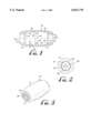
- FIG. 1 is a cross-sectional view of the roller of the present invention.
- FIG. 2 is an end view of the roller of FIG. 1.
- FIG. 3 is a perspective view of the roller of FIG. 1, including a bearing assembly.
- the cargo roller shown in U.S. Pat. No. 3,753,541 is strengthened by a series of longitudinal stiffening ribs formed within the inner cavity. Hubs are pressed into each end and secured to the roller by swaging the end portions of the roller. A bearing assembly is then held in the cavity of the hub.
- the outer surface of the roller is slightly crowned and the inner surface is straight.
- the inventor's desire was to provide an improved cargo roller which would not have a tendency to break at the inner edge of the hubs 23 and which could be manufactured economically while still having increased strength.
- the cargo roller is indicated by reference character 10 and has an outer surface 11 of the roller portion 12.
- First and second bearing cavities 13 and 14 are formed at each end 16 and 16' and preferably include stop rings 15 and 15'.
- a bearing assembly such as that indicated by reference character 17 in FIG. 2 is pressed into bearing cavity 13 until its inner surface abuts stop ring 15. It is then staked at stake points 28 or otherwise held in the cavity.
- the combination of light weight and strength of the cargo roller of the present invention is the result of the shape of the inner hollow inner cavity 18 within the inner volume of the roller.
- the inner volume is intended to mean the entire volume of the roller within outer surface 11.
- the hollow inner cavity 18 is formed with at least one stiffening ring 20 which greatly increases the strength of the roller and its ability to withstand shock loads.
- outer surface 11 is slightly crowned as shown in the drawings and the inner cavity 18 is also slightly crowned so that a wall thickness 21 is constant along a majority of the length of the roller.
- the roller rotates around a central axis of rotation 22 and the outer surface may be formed in any desired shape as long as any portion of the outer surface forms a circle when viewed in a direction normal to the central axis of rotation 22.
- Another important feature of the present invention is its elimination of a hub which thereby forms three areas of maximum thickness in the roller: one around stop ring 15, one around stiffening ring 20 and the third around stop ring 15'.
- the areas of weakness of the prior art roller of U.S. Pat. No. 3,753,541 are eliminated.
- the roller is formed from an aluminum alloy, but of course, other materials of construction may be available which provide improved strength to weight ratios.
- stiffening ring 20 has a fillet, such as fillet 23. Also, fillets 24 and 25 are preferred adjacent the stop rings 15 and 15'.
Abstract
A cargo roller for use in a roller assembly useful in aircraft or other applications where a high strength to weight ratio is important. The cargo roller includes an outer roller surface and an inner surface which includes at least one stiffening ring formed circumferencially in an inner cavity of the roller. A bearing cavity is formed at each end and preferably the entire assembly is formed from a single piece of aluminum or other appropriate material.
Description
The field of the invention is cargo rollers and the invention relates more particularly to cargo rollers widely used in commercial aircraft. A widely used cargo roller assembly is shown in U.S. Pat. No. 3,753,541. Although the roller used in this assembly has been widely accepted, it has been known to break at a position between hub 23 and the stiffening ribs. A broken roller creates a great deal of potential difficulty in moving cargo within the cargo area of an aircraft and, thus, a stronger, yet still lightweight, roller is needed.
The present invention is for a cargo roller for use in a roller assembly useful in aircraft or other applications where high strength to weight ratio is important. The roller has an outer surface, which although generally cylindrical, is preferably slightly crowned. Means are provided for supporting a bearing at each end of the roller and the inner volume of the roller is partially hollowed out to reduce weight. In this hollowed out portion one or more stiffening rings are positioned which are preferably formed of the same material as the body of the roller. Preferably, the roller assembly has bearing cavities at each end with a bearing stop or hub portion which also extends slightly into the inner cavity. Preferably, the inner cavity is slightly crowned to follow the shape of the outer surface of the roller so that the wall thickness is constant along a majority of the width of the roller.
FIG. 1 is a cross-sectional view of the roller of the present invention.
FIG. 2 is an end view of the roller of FIG. 1.
FIG. 3 is a perspective view of the roller of FIG. 1, including a bearing assembly.
The cargo roller shown in U.S. Pat. No. 3,753,541 is strengthened by a series of longitudinal stiffening ribs formed within the inner cavity. Hubs are pressed into each end and secured to the roller by swaging the end portions of the roller. A bearing assembly is then held in the cavity of the hub. The outer surface of the roller is slightly crowned and the inner surface is straight. The inventor's desire was to provide an improved cargo roller which would not have a tendency to break at the inner edge of the hubs 23 and which could be manufactured economically while still having increased strength. The inventor created a shape which is shown best in FIG. 1 of the drawings. The cargo roller is indicated by reference character 10 and has an outer surface 11 of the roller portion 12. First and second bearing cavities 13 and 14 are formed at each end 16 and 16' and preferably include stop rings 15 and 15'. A bearing assembly such as that indicated by reference character 17 in FIG. 2 is pressed into bearing cavity 13 until its inner surface abuts stop ring 15. It is then staked at stake points 28 or otherwise held in the cavity.
The combination of light weight and strength of the cargo roller of the present invention is the result of the shape of the inner hollow inner cavity 18 within the inner volume of the roller. The inner volume is intended to mean the entire volume of the roller within outer surface 11. The hollow inner cavity 18 is formed with at least one stiffening ring 20 which greatly increases the strength of the roller and its ability to withstand shock loads.
Preferably, outer surface 11 is slightly crowned as shown in the drawings and the inner cavity 18 is also slightly crowned so that a wall thickness 21 is constant along a majority of the length of the roller. The roller rotates around a central axis of rotation 22 and the outer surface may be formed in any desired shape as long as any portion of the outer surface forms a circle when viewed in a direction normal to the central axis of rotation 22.
Another important feature of the present invention is its elimination of a hub which thereby forms three areas of maximum thickness in the roller: one around stop ring 15, one around stiffening ring 20 and the third around stop ring 15'. Thus, the areas of weakness of the prior art roller of U.S. Pat. No. 3,753,541 are eliminated.
Preferably, the roller is formed from an aluminum alloy, but of course, other materials of construction may be available which provide improved strength to weight ratios.
A single stiffening ring is shown in the drawings, but it is within the purview of the present invention that two or more stiffening rings can be made. Preferably, the stiffening ring 20 has a fillet, such as fillet 23. Also, fillets 24 and 25 are preferred adjacent the stop rings 15 and 15'.
The present embodiments of this invention are thus to be considered in all respects as illustrative and not restrictive; the scope of the invention being indicated by the appended claims rather than by the foregoing description. All changes which come within the meaning and range of equivalency of the claims are intended to be embraced therein.
Claims (10)
1. A cargo roller for use in a roller assembly useful in aircraft or other applications where high strength to weight ratio is essential, said cargo roller being free of any axle housing, said cargo roller comprising:
a roller portion having an outer surface which forms a circle when viewed normal to a central axis of rotation, said roller portion having a first end and a second end, each end having means for supporting a bearing assembly centered about said central axis of rotation, and a portion of an inner volume of said roller portion within said outer surface having a hollow inner cavity and including at least one stiffening ring formed normal to said axis of rotation and said stiffening ring having an inside diameter less than an average inside diameter of said hollow inner cavity, said stiffening ring being spaced from said means for supporting a bearing assembly at each end of said roller portion.
2. The cargo roller of claim 1 wherein said stiffening ring is positioned midway between said first end and said second end.
3. The cargo roller of claim 1 wherein said stiffening ring and said roller portion are integrally formed.
4. The cargo roller of claim 3 wherein said stiffening ring is filleted in said hollow inner cavity.
5. The cargo roller of claim 3 wherein said roller portion has a bearing cavity at said first end and said second end.
6. The cargo roller of claim 5 wherein said bearing cavity at said first end and said second end has a bearing stop which has an inner edge which is filleted.
7. The cargo roller of claim 6 wherein a bearing assembly is pressed into said cavity at said first end and said cavity at said second end without the use of an intermediate hub.
8. A cargo roller assembly useful in aircraft or other applications where high strength to weight ratio is essential, said cargo roller assembly including a bearing cavity supporting a bearing at a first end, a bearing cavity supporting a bearing at a second end, and said cargo roller assembly being free of any axle housing, said cargo roller comprising:
a roller portion having a slightly crowned outer surface which forms a circle when viewed normal at any point along a central axis of rotation, said roller portion having a first end and a second end, each end having means for supporting a bearing assembly centered about said central axis of rotation and a portion of an inner volume of said roller portion within said outer surface having a hollow inner cavity and including one stiffening ring formed midway between said first end and said second end and formed normal to said axis of rotation and said stiffening ring having an inside diameter less than an average inside diameter of said hollow inner cavity, said stiffening ring being spaced from said means for supporting a bearing assembly at each end of said roller portion.
9. The cargo roller assembly of claim 8 wherein said roller portion has three areas of maximum wall thickness, one of said areas being at a mid-point between said first end and said second end, a second area being at an inner edge of said means for supporting a bearing assembly and said third area being at an inner edge of said means for supporting a bearing assembly at said second end.
10. A cargo roller for use in a roller assembly useful in aircraft or other applications where high strength to weight ratio is essential, said cargo roller comprising:
a roller portion having a slightly crowned outer surface which forms a circle when viewed normal at any point along a central axis of rotation, said roller portion having a first end and a second end, each end having means for supporting a bearing assembly centered about said central axis of rotation and a portion of an inner volume of said roller portion within said outer surface having a hollow inner cavity and including one stiffening ring formed midway between said first end and said second end and formed normal to said axis of rotation and said stiffening ring having an inside diameter less than an average inside diameter of said hollow inner cavity, said stiffening ring being spaced from said means for supporting a bearing assembly at each end of said roller portion, and wherein said hollow inner cavity has a crowned portion which follows the shape of the outer crown surface in such a manner that a wall thickness along a majority of the hollow cavity is constant.
Priority Applications (1)
| Application Number | Priority Date | Filing Date | Title |
|---|---|---|---|
| US09/205,215 US6032778A (en) | 1998-12-04 | 1998-12-04 | Cargo roller |
Applications Claiming Priority (1)
| Application Number | Priority Date | Filing Date | Title |
|---|---|---|---|
| US09/205,215 US6032778A (en) | 1998-12-04 | 1998-12-04 | Cargo roller |
Publications (1)
| Publication Number | Publication Date |
|---|---|
| US6032778A true US6032778A (en) | 2000-03-07 |
Family
ID=22761296
Family Applications (1)
| Application Number | Title | Priority Date | Filing Date |
|---|---|---|---|
| US09/205,215 Expired - Fee Related US6032778A (en) | 1998-12-04 | 1998-12-04 | Cargo roller |
Country Status (1)
| Country | Link |
|---|---|
| US (1) | US6032778A (en) |
Cited By (5)
| Publication number | Priority date | Publication date | Assignee | Title |
|---|---|---|---|---|
| US6746387B2 (en) * | 2001-07-10 | 2004-06-08 | Kryptane Systems, Inc. | Agricultural roller |
| US20040214700A1 (en) * | 2001-07-10 | 2004-10-28 | Lane John L. | Agricultural roller |
| US20070243983A1 (en) * | 2006-04-13 | 2007-10-18 | Stellar Industries, Inc. | Roller assembly for use in conveying heavy loads |
| US20090273133A1 (en) * | 2008-04-30 | 2009-11-05 | Sutton Donald C | Roller |
| US20110042854A1 (en) * | 2008-04-30 | 2011-02-24 | Hirohisa Abe | Sheet feed rolling element for use in an electrophotographic device and mold for injection molding for producing the sheet feed rolling element |
Citations (8)
| Publication number | Priority date | Publication date | Assignee | Title |
|---|---|---|---|---|
| US1286343A (en) * | 1917-11-28 | 1918-12-03 | Stephens Adamson Mfg Company | Pulley. |
| US3363735A (en) * | 1966-03-16 | 1968-01-16 | Lockheed Aircraft Corp | Roller |
| US3559782A (en) * | 1968-04-22 | 1971-02-02 | Kathryn W Lesley | Conveyor roller and method of manufacturing same |
| US3753541A (en) * | 1971-09-02 | 1973-08-21 | Mc Donnell Douglas Corp | Cargo roller assembly |
| US4790421A (en) * | 1987-10-22 | 1988-12-13 | The Boeing Company | Roller assembly |
| US5381887A (en) * | 1994-01-12 | 1995-01-17 | Elastomer Specialties, Inc. | Conveyor systems and high durability rollers therefor |
| US5548897A (en) * | 1993-08-30 | 1996-08-27 | Link; Terry G. | Method of fabricating lightweight ink transfer roll |
| US5655642A (en) * | 1995-05-22 | 1997-08-12 | Fmc Corporation | Idler roll for use in belt conveyor systems |
-
1998
- 1998-12-04 US US09/205,215 patent/US6032778A/en not_active Expired - Fee Related
Patent Citations (8)
| Publication number | Priority date | Publication date | Assignee | Title |
|---|---|---|---|---|
| US1286343A (en) * | 1917-11-28 | 1918-12-03 | Stephens Adamson Mfg Company | Pulley. |
| US3363735A (en) * | 1966-03-16 | 1968-01-16 | Lockheed Aircraft Corp | Roller |
| US3559782A (en) * | 1968-04-22 | 1971-02-02 | Kathryn W Lesley | Conveyor roller and method of manufacturing same |
| US3753541A (en) * | 1971-09-02 | 1973-08-21 | Mc Donnell Douglas Corp | Cargo roller assembly |
| US4790421A (en) * | 1987-10-22 | 1988-12-13 | The Boeing Company | Roller assembly |
| US5548897A (en) * | 1993-08-30 | 1996-08-27 | Link; Terry G. | Method of fabricating lightweight ink transfer roll |
| US5381887A (en) * | 1994-01-12 | 1995-01-17 | Elastomer Specialties, Inc. | Conveyor systems and high durability rollers therefor |
| US5655642A (en) * | 1995-05-22 | 1997-08-12 | Fmc Corporation | Idler roll for use in belt conveyor systems |
Cited By (8)
| Publication number | Priority date | Publication date | Assignee | Title |
|---|---|---|---|---|
| US6746387B2 (en) * | 2001-07-10 | 2004-06-08 | Kryptane Systems, Inc. | Agricultural roller |
| US20040214700A1 (en) * | 2001-07-10 | 2004-10-28 | Lane John L. | Agricultural roller |
| US7201713B2 (en) | 2001-07-10 | 2007-04-10 | Kryptane Systems, Llc | Agricultural roller |
| US20070243983A1 (en) * | 2006-04-13 | 2007-10-18 | Stellar Industries, Inc. | Roller assembly for use in conveying heavy loads |
| US20090273133A1 (en) * | 2008-04-30 | 2009-11-05 | Sutton Donald C | Roller |
| US20110042854A1 (en) * | 2008-04-30 | 2011-02-24 | Hirohisa Abe | Sheet feed rolling element for use in an electrophotographic device and mold for injection molding for producing the sheet feed rolling element |
| US8206277B2 (en) * | 2008-04-30 | 2012-06-26 | Hewlett-Packard Development Company, L.P. | Idler roller assembly having a roller and a shaft the roller being formed such that it remains parallel to contacted media despite deflection of the shaft |
| US8932193B2 (en) * | 2008-04-30 | 2015-01-13 | Ntn Corporation | Sheet feed rolling element for use in an electrophotographic device and mold for injection molding for producing the sheet feed rolling element |
Similar Documents
| Publication | Publication Date | Title |
|---|---|---|
| US4540385A (en) | Drive shaft assembly | |
| CA1089810A (en) | Cargo roller | |
| EP0814261A3 (en) | Compressor piston | |
| US6032778A (en) | Cargo roller | |
| US5010785A (en) | Crank arm for a bicylce | |
| US5761769A (en) | Door hinge for a motor vehicle door with a braking and retaining function | |
| FR2613443A1 (en) | HOMOCINETIC JOINT ALLOWING AXIAL SLIDING; AND TRANSMISSION SHAFTS COMPRISING AT LEAST ONE SUCH JOINT | |
| CA2011501A1 (en) | Self-aligning bearing | |
| DE3642875C2 (en) | ||
| US6913323B2 (en) | Wheel having spokes with V-shaped cross-sections | |
| US20030071432A1 (en) | Transverse strut for a twist-beam axle of a motor vehicle | |
| US4693136A (en) | Telescopic sub-assembly for a steering column | |
| JP3016188B2 (en) | Differential gear with differential gear inner support | |
| US4010625A (en) | Sliding homokinetic joint | |
| JP2676690B2 (en) | Differential device having a differential pinion with spherical bearing shaft | |
| EP0404530A1 (en) | Suspension unit | |
| FR2571798A1 (en) | HOMOCINETIC JOINT | |
| US5292287A (en) | Hub assembly for a rear wheel axle of a bicycle | |
| EP1233874B1 (en) | Safety support and support and rim assembly for tyre comprising centring means for easy mounting | |
| US5728025A (en) | Differential apparatus | |
| JPS58217818A (en) | Self-alignment bearing | |
| US9664253B2 (en) | Crowned profile driveshaft journal | |
| US2496615A (en) | Wheel and wheel mounting | |
| CA2056694A1 (en) | Nonseparable thrust ball bearing | |
| JPH04328001A (en) | Built-up wheel hub |
Legal Events
| Date | Code | Title | Description |
|---|---|---|---|
| REMI | Maintenance fee reminder mailed | ||
| FEPP | Fee payment procedure |
Free format text: PETITION RELATED TO MAINTENANCE FEES FILED (ORIGINAL EVENT CODE: PMFP); ENTITY STATUS OF PATENT OWNER: SMALL ENTITY |
|
| FEPP | Fee payment procedure |
Free format text: PETITION RELATED TO MAINTENANCE FEES GRANTED (ORIGINAL EVENT CODE: PMFG); ENTITY STATUS OF PATENT OWNER: SMALL ENTITY |
|
| REIN | Reinstatement after maintenance fee payment confirmed | ||
| FP | Lapsed due to failure to pay maintenance fee |
Effective date: 20040307 |
|
| FPAY | Fee payment |
Year of fee payment: 4 |
|
| SULP | Surcharge for late payment | ||
| PRDP | Patent reinstated due to the acceptance of a late maintenance fee |
Effective date: 20040916 |
|
| REMI | Maintenance fee reminder mailed | ||
| LAPS | Lapse for failure to pay maintenance fees | ||
| STCH | Information on status: patent discontinuation |
Free format text: PATENT EXPIRED DUE TO NONPAYMENT OF MAINTENANCE FEES UNDER 37 CFR 1.362 |
|
| FP | Lapsed due to failure to pay maintenance fee |
Effective date: 20080307 |