US6032505A - Tooling apparatus and method for high speed production of drawn metal cup-like articles - Google Patents
Tooling apparatus and method for high speed production of drawn metal cup-like articles Download PDFInfo
- Publication number
- US6032505A US6032505A US08/679,770 US67977096A US6032505A US 6032505 A US6032505 A US 6032505A US 67977096 A US67977096 A US 67977096A US 6032505 A US6032505 A US 6032505A
- Authority
- US
- United States
- Prior art keywords
- draw
- annular
- blank
- die
- stages
- Prior art date
- Legal status (The legal status is an assumption and is not a legal conclusion. Google has not performed a legal analysis and makes no representation as to the accuracy of the status listed.)
- Expired - Fee Related
Links
- 229910052751 metal Inorganic materials 0.000 title claims abstract description 29
- 239000002184 metal Substances 0.000 title claims abstract description 29
- 238000000034 method Methods 0.000 title claims description 24
- 238000004519 manufacturing process Methods 0.000 title description 5
- 230000009471 action Effects 0.000 claims abstract description 15
- 238000005520 cutting process Methods 0.000 claims description 5
- 125000006850 spacer group Chemical group 0.000 description 9
- 230000007423 decrease Effects 0.000 description 3
- 230000009467 reduction Effects 0.000 description 2
- 230000000717 retained effect Effects 0.000 description 2
- 230000002441 reversible effect Effects 0.000 description 2
- 229910000831 Steel Inorganic materials 0.000 description 1
- 229910052782 aluminium Inorganic materials 0.000 description 1
- XAGFODPZIPBFFR-UHFFFAOYSA-N aluminium Chemical compound [Al] XAGFODPZIPBFFR-UHFFFAOYSA-N 0.000 description 1
- 235000013361 beverage Nutrition 0.000 description 1
- 230000004069 differentiation Effects 0.000 description 1
- 239000012530 fluid Substances 0.000 description 1
- 230000001788 irregular Effects 0.000 description 1
- 239000000463 material Substances 0.000 description 1
- 230000004048 modification Effects 0.000 description 1
- 238000012986 modification Methods 0.000 description 1
- 230000000750 progressive effect Effects 0.000 description 1
- 238000004080 punching Methods 0.000 description 1
- 238000002407 reforming Methods 0.000 description 1
- 230000000284 resting effect Effects 0.000 description 1
- 238000007789 sealing Methods 0.000 description 1
- 238000012163 sequencing technique Methods 0.000 description 1
- 238000010008 shearing Methods 0.000 description 1
- 239000010959 steel Substances 0.000 description 1
Images

Classifications
-
- B—PERFORMING OPERATIONS; TRANSPORTING
- B21—MECHANICAL METAL-WORKING WITHOUT ESSENTIALLY REMOVING MATERIAL; PUNCHING METAL
- B21D—WORKING OR PROCESSING OF SHEET METAL OR METAL TUBES, RODS OR PROFILES WITHOUT ESSENTIALLY REMOVING MATERIAL; PUNCHING METAL
- B21D53/00—Making other particular articles
- B21D53/46—Making other particular articles haberdashery, e.g. buckles, combs; pronged fasteners, e.g. staples
- B21D53/48—Making other particular articles haberdashery, e.g. buckles, combs; pronged fasteners, e.g. staples buttons, e.g. press-buttons, snap fasteners
-
- B—PERFORMING OPERATIONS; TRANSPORTING
- B21—MECHANICAL METAL-WORKING WITHOUT ESSENTIALLY REMOVING MATERIAL; PUNCHING METAL
- B21D—WORKING OR PROCESSING OF SHEET METAL OR METAL TUBES, RODS OR PROFILES WITHOUT ESSENTIALLY REMOVING MATERIAL; PUNCHING METAL
- B21D22/00—Shaping without cutting, by stamping, spinning, or deep-drawing
- B21D22/20—Deep-drawing
- B21D22/24—Deep-drawing involving two drawing operations having effects in opposite directions with respect to the blank
-
- B—PERFORMING OPERATIONS; TRANSPORTING
- B21—MECHANICAL METAL-WORKING WITHOUT ESSENTIALLY REMOVING MATERIAL; PUNCHING METAL
- B21D—WORKING OR PROCESSING OF SHEET METAL OR METAL TUBES, RODS OR PROFILES WITHOUT ESSENTIALLY REMOVING MATERIAL; PUNCHING METAL
- B21D22/00—Shaping without cutting, by stamping, spinning, or deep-drawing
- B21D22/20—Deep-drawing
- B21D22/28—Deep-drawing of cylindrical articles using consecutive dies
-
- B—PERFORMING OPERATIONS; TRANSPORTING
- B21—MECHANICAL METAL-WORKING WITHOUT ESSENTIALLY REMOVING MATERIAL; PUNCHING METAL
- B21D—WORKING OR PROCESSING OF SHEET METAL OR METAL TUBES, RODS OR PROFILES WITHOUT ESSENTIALLY REMOVING MATERIAL; PUNCHING METAL
- B21D24/00—Special deep-drawing arrangements in, or in connection with, presses
- B21D24/16—Additional equipment in association with the tools, e.g. for shearing, for trimming
-
- B—PERFORMING OPERATIONS; TRANSPORTING
- B21—MECHANICAL METAL-WORKING WITHOUT ESSENTIALLY REMOVING MATERIAL; PUNCHING METAL
- B21D—WORKING OR PROCESSING OF SHEET METAL OR METAL TUBES, RODS OR PROFILES WITHOUT ESSENTIALLY REMOVING MATERIAL; PUNCHING METAL
- B21D28/00—Shaping by press-cutting; Perforating
- B21D28/02—Punching blanks or articles with or without obtaining scrap; Notching
- B21D28/06—Making more than one part out of the same blank; Scrapless working
-
- B—PERFORMING OPERATIONS; TRANSPORTING
- B21—MECHANICAL METAL-WORKING WITHOUT ESSENTIALLY REMOVING MATERIAL; PUNCHING METAL
- B21D—WORKING OR PROCESSING OF SHEET METAL OR METAL TUBES, RODS OR PROFILES WITHOUT ESSENTIALLY REMOVING MATERIAL; PUNCHING METAL
- B21D51/00—Making hollow objects
- B21D51/16—Making hollow objects characterised by the use of the objects
- B21D51/26—Making hollow objects characterised by the use of the objects cans or tins; Closing same in a permanent manner
-
- B—PERFORMING OPERATIONS; TRANSPORTING
- B21—MECHANICAL METAL-WORKING WITHOUT ESSENTIALLY REMOVING MATERIAL; PUNCHING METAL
- B21D—WORKING OR PROCESSING OF SHEET METAL OR METAL TUBES, RODS OR PROFILES WITHOUT ESSENTIALLY REMOVING MATERIAL; PUNCHING METAL
- B21D51/00—Making hollow objects
- B21D51/16—Making hollow objects characterised by the use of the objects
- B21D51/38—Making inlet or outlet arrangements of cans, tins, baths, bottles, or other vessels; Making can ends; Making closures
Definitions
- punch and die tooling for blanking or cutting a plurality of parts from a sheet metal workpiece with each stroke of the press and by positioning each punch at a slightly different elevation corresponding to the thickness of the sheet metal workpiece.
- the blanking or punching of the parts is performed in sequence, but the holding of the workpiece is performed by one plate without any sequence.
- the present invention is directed to an improved method and apparatus for constructing and operating the tooling for a press for producing a plurality of cup-like articles with each stroke of the press and which provides for significantly increasing the operational speed of the press to obtain a higher production rate without overloading components of the press.
- a cupping press equipped with tooling constructed in accordance with the present invention is capable of obtaining more than a 50% decrease in the compressive forces or loading on the outer ram and this decrease permits the speed of the press to be increased from about 150 spm to about 250 spm without exceeding the load rating of the press.
- a cupping press is equipped with multiple stage tooling wherein each tooling stage includes a plurality of annular draw pads each opposing a corresponding annular blank and draw die, an annular cut edge die surrounding each of the draw pads and a corresponding die center punch within each of the draw pads.
- the tooling stages are constructed for sequentially engaging the sheet metal with a precise timing sequence which provides for sequentially blanking a series of circular blanks between the cut edge dies and the corresponding blank and draw dies during each stroke of the press, sequentially holding the blanks between the draw pads and the corresponding blank and draw dies, and then sequentially drawing the blanks into cups with the die center punches extending into the corresponding blank and draw dies.
- the tooling of an existing cupping press may be easily modified by installing a series of annular shims for some of the draw pads and the retainers for the cut edge dies and by lowering the retainers supporting some of the blank and draw dies.
- the tooling at each stage may also include a pressure sleeve surrounding a bottom panel punch within the blank and draw die for forming a preform boss within the bottom wall of each cup.
- the present invention further provides for conveniently and quickly removing upper and lower tooling components to simplify servicing of the tooling after an extended period of use.
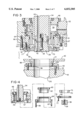
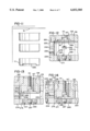
- FIG. 1 is a general plan view of lower cup forming tooling constructed in accordance with the invention and with the stock plate removed;
- FIG. 2 is a fragmentary section of the upper and lower cup forming tooling in a double action press, and showing the multiple stages of the tooling as taken generally on the line 2--2 of FIG. 1;
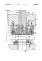
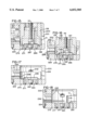
- FIG. 3 is an enlarged fragmentary section of one of the tooling stages shown in FIG. 2;
- FIG. 4 is a fragmentary exploded view illustrating the assembly of upper tooling components shown in FIG. 3;
- FIGS. 5-7 are enlarged fragmentary sections of the tooling components shown in FIGS. 2 & 3 and illustrating the sequential blanking, holding and drawing operations in accordance with invention
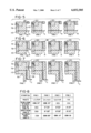
- FIG. 8 is a chart illustrating the relative positions of the multiple stage or stepped tooling components shown in and FIGS. 2 & 5-7;
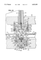
- FIG. 9 is a fragmentary section similar to FIG. 3 and showing a modification of a tooling stage.
- FIG. 10 is a fragmentary section similar to FIGS. 3 and 9 and showing another tooling embodiment of the invention.
- FIG. 11 generally illustrates the drawing of a cup with a bottom preform boss using the tooling shown in FIG. 10;
- FIGS. 12-18 are fragmentary sections of the tooling components shown in FIG. 10 at different progressive positions for forming the cup shown in FIG. 11.
- FIG. 1 illustrates a plan view of the lower or bottom tooling of a fourteen cup tooling system 15 which includes a lower die shoe 18 secured to a bed 20 (FIG. 2) of a double action mechanical press.
- the press also includes an inner ram 22 and an outer ram 24, with the inner ram 22 having a vertical stroke, for example, of about five inches and the outer ram 24 having a substantially shorter stroke, for example, about two inches.
- the lower die shoe 18 has a series of fourteen holes or pockets 26 which extend vertically or downwardly through the lower die shoe 18 to a cup discharge chamber 28.
- the pockets 26 are arranged in four stages (FIG. 1) with pockets 1, 2, 13 and 14 forming stage 1, pockets 3, 4, 11 and 12 forming stage 2, pockets 5, 6, 9 and 10 forming stage 3 and pockets 7 and 8 forming the center stage 4.
- the inner ram 22 (FIG. 2) supports an upper or inner die shoe 32.
- a series of vertical risers 34 are secured to the bottom surface of the inner die shoe 32 and extend downwardly in vertical alignment with the corresponding pockets 26.
- a die center punch 38 (FIG. 3) is secured to the lower end portion of each riser 34 by a center screw 39 and a precision locator pin 41, and each die center punch 38 carries a hardened outer wear sleeve 42.
- Each of the risers 34 and the corresponding die center punch 38 have a vertically extending air passage 44 which receives a supply of pressurized air at timed intervals for removing cups from the punch.
- the risers 34 and corresponding die center punches 38 are carried by and move vertically with the inner ram 22 through the attached inner die shoe 32.
- a cylindrical guide sleeve 46 (FIG. 3) surrounds each of the risers 34 and has an upper flange secured to an annular plate 48 which is mounted on an upper die shoe 52.
- the upper die shoe 52 is carried by the outer ram 24 through a series of peripherally spaced screws 54 (FIG. 2).
- a cylindrical liner 57 lines a bore within the upper die shoe 52 and cooperates with the sleeve 46 and plate 48 to define a fluid or air chamber 59 which receives the head portion of a piston 62.
- the head portion carries wear pads (not shown) within peripherally spaced holes 63 and is confined within the chamber 59 by an annular retainer 64 secured to the upper die shoe 52 by peripherally spaced screws 66 and a precision locator pin 67.
- a two section draw pad 70 is supported for vertical sliding movement within the annular retainer 64 below the piston 62, and the bottom surface of the draw pad 70 has a series of fine concentric grooves or recesses to form an irregular surface.
- the lower portion of the draw pad 70 is formed from a harder steel than the upper portion which engages the piston 62 and carries wear pads (not shown) within peripherally spaced holes 73.
- the draw pad 70 is retained within the annular retainer 64 by an annular cut edge retainer 74 secured to the retainer 64 by a series of peripherally spaced screws 77.
- the retainer 74 supports a hardened annular shearing die or cut edge 78 which surrounds the draw pad 70.
- a hardened flat spacer ring 82 is recessed within the upper portion of the cut edge retainer 74 and forms a lower limit of movement for the draw pad 70.
- each of the holes or pockets 26 within the lower die shoe 18 is vertically aligned with the corresponding die center punch 38 and is slightly larger in diameter.
- a two section annular blank and draw die 90 which is supported in a circular recess of an annular retainer 93 by a flat annular spacer 96.
- Each blank and draw die 90 is secured to its corresponding retainer 93 by a set of peripherally spaced screws 98, and another set of screws 101 secures each retainer 93 to the lower die shoe 18.
- a set of screws 102 secures the spacer 96 to the blank and draw die 90.
- Locating pins and bushings are also used to align each blank and draw die 90 and its retainer 93 precisely on the lower die shoe 18.
- the upper portion or section of the blank and draw die 90 consists of a hardened ring which is inserted and positively retained within the lower portion or section of the die 90.
- the die center punch 38, draw pad 70, surrounding cut edge retainer 74 and cut edge 78, piston 62 and piston retainer 64, which form part of the upper tooling on the upper die shoe 52, may be conveniently and quickly removed from the die shoe 52, simply by removing the screws 39, 66 and 77. Furthermore, these components may be removed for replacing components such as wear pads or piston sealing rings without further elevation of the upper die shoe 52 or without further disassembly of the upper tooling.
- a flat stock plate 110 forms part of the bottom or lower tooling and defines a circular opening or clearance hole 111 for receiving each of the blank and draw dies 90.
- the stock plate 110 is supported with its upper surface generally flush with the upper surface of the blank and draw dies 90 by a series of spring biased pistons 115 (FIG. 2) which are located within the lower die shoe 18 between and around the blank and draw dies 90, as shown in FIG. 1.
- the spring loaded pistons 115 biased the stock plate 110 to its elevated position (FIGS. 2 and 3) with a predetermined force, but permit the stock plate 110 to move downwardly by a fraction of an inch when the force is exceeded by the downward movement of the cut edges 78 and retainers 74.
- the multiple stage tooling described above in connection with FIGS. 1-4 operates to perform sequential blanking, holding and drawing operations with respect to sets of the holes or pockets 26. These sequential operations are performed by precisely positioning each stage of the blank and draw dies 90, the draw pads 70 and the die center punches 38 at predetermined elevations relative to the press bed 20.
- existing cupping tooling may be modified by grinding the bottom surfaces of some of the blank and draw die retainers 93 to lower the blank and draw dies, and by adding a set of shims to the upper tooling for each of the stages 2, 3 and 4.
- a flat annular shim 120 limits the downward movement of each draw pad 70 relative to its surrounding cut edge 78
- an annular flat shim 121 limits the downward movement of the corresponding air actuated piston 62 which presses downwardly with a predetermined pressure on the draw pad 70.
- Another annular flat shim 122 spaces or lowers each of some of the die center punches 38 with respect to its supporting riser 34 and precisely determines the elevation of the die center punch with respect to its surrounding draw pad 70.
- the blank and draw dies 90 for the holes of stages 1 and 2 are each lowered by 0.012 inch. This lowering is accomplished by grinding the bottom surfaces of the retainers 93 supporting the corresponding blank and draw dies 90.
- the shims 120 and 121 for the stage 2 pockets 3, 4, 11 and 12 have a thickness of 0.020 inch so that the pistons 62 for the pockets of stage 2 and the corresponding draw pads 70 are elevated by 0.020 inch above the pistons 62 and draw pads 70 for the stage 1 pockets 1, 2, 13 and 14.
- the die center shims 122 for the stage 2 pockets 3, 4, 11 and 12 have a thickness of 0.060 inch so that the die center punches 38 for these pockets are lowered by 0.060 inch relative to the die center punches for the stage 1 pockets.
- the shims 120 and 121 for the stage 3 pockets 5, 6, 9 and 10 have a thickness of 0.052 inch so that the pistons 62 and draw pads 70 for these pockets are elevated by 0.040 inch above the draw pads 70 for the stage 2 pockets.
- the die center punch shims 122 for the stage 3 pockets have a thickness of 0.116 inch so that the die center punches 38 for these pockets are 0.056 inch lower than the die center punches for the stage 2 pockets.
- the shims 120 and 121 for the stage 4 pockets 7 and 8 have thickness of 0.072 inch
- the die center punch shims 122 for these pockets have a thickness 0.198 inch so that the draw pads for these pockets are elevated by 0.020 inch above the draw pads 70 for the stage 3 pockets, and the die center punches 38 for the stage 4 pockets are 0.082 inch lower than the die center punches
- a sheet S of metal such as 0.011 inch thick aluminum, is fed between the upper tooling and lower tooling in the downward direction in FIG. 1.
- the downward movement of the outer ram 24 and the upper die shoe 52 causes the sheet S to be sequentially sheared or blanked between the annular cut edges 78 and the annular blank and draw dies 90 for the stages 1-4 for progressively forming the flat circular blanks B.
- the blanks B are sequentially clamped or held against the blank and draw dies 90 by the draw pads 70 for the stages 1-4 as a result of the shims 120 and 121 with increasing thickness.
- the downward movement of the inner ram 22 and inner die shoe 32 causes the die center punches 38 for the stages 1-4 to engage the blanks B sequentially and to draw the blanks sequentially into corresponding cups C.
- the increasing thickness of the shims 122 above the die center punches 38 for stages 1-4 results in the cups C being sequentially drawn in a reverse order, with the cups C for stage 4 being fully drawn prior to the cups for stage 3 being fully drawn and prior to the cups for stage 2 being fully drawn prior to the cups at stage 1.
- FIG. 9 illustrates a fragmentary section of cup forming tooling constructed in accordance with another embodiment of the invention and similar to the cup forming tooling described above in connection with FIGS. 3 and 4.
- an upper die shoe 130 is connected to the outer ram 24 for vertical reciprocating movement, for example, with a stroke of about two inches.
- a cylindrical bore 132 is formed within the upper die shoe 130 for each of the tooling pockets or stations and slidably supports a corresponding riser 134 which is connected to the inner die shoe 32 for vertical reciprocating movement with a stroke, for example, of about 5 inches.
- the lower end portion of each riser 134 carries an annular die center punch 136 secured to the riser by an annular hub 138 and a center screw 141.
- An annular spacer shim or ring 143 is located between the die center punch 136 and an annular shoulder on the riser 134, and the spacer ring 143 is secured to the riser 134 by a series of peripherally spaced screws 144.
- An air passage 147 extends axially within the riser 134 and hub 138 for receiving pulses of pressurized air, as explained above in connection with the air passage 44.
- An annular body or retainer 150 surrounds each of the risers 134 and corresponding die center punch 136 and is attached to the bottom surface of the upper die shoe 130 by a series of circumferentially spaced and axially extending screws 153 and a set of precision locating pins 154.
- the retainer 150 defines an annular chamber 158 which receives pressurized air through a passage 159 within the upper die shoe 130.
- An annular piston 165 is supported within the chamber 158 for axial movement and has a lower portion connected directly to an annular draw pad 168 which surrounds the die center punch 136.
- the draw pad 168 is preferably formed of a harder material than the piston 165 and is attached by a press-fit connection.
- An annular cut edge die 172 surrounds the draw pad 168 and is secured to an annular cut edge retainer 174 by a press-fit connection.
- a flat spacer ring 177 is secured to the cut edge retainer 174 by a series of circumferentially spaced screws 176, and a retainer ring 182 is secured to the retainer 150 by a series of circumferentially spaced and axially extending screws 183.
- the ring 182 forms a seat for the piston 165 and limits the downward movement of the piston 165.
- a series of circumferentially spaced screws 186 extend axially through aligned holes within the cut edge retainer 174, spacer ring 177 and retainer ring 182, and are threaded into the retainer 150. As apparent from FIG.
- removal of the screws 186 permits convenient removal of the cut edge die 172 and die retainer 174, and removal of the screws 183 provide for convenient removal of the retainer ring 182 and the piston 165 with the attached draw pad 168.
- the retainer 150 may be removed by removing the screws 153.
- the tooling components mounted on the lower die shoe 18 are substantially identical to the lower tooling components described above in connection with FIG. 3, the same reference numbers are used for the various components or parts. As apparent from a comparison of the upper tooling shown in FIG. 9 and the upper tooling shown in FIG. 3, the tooling of FIG. 9 performs the same function but uses significantly fewer parts.
- the tooling components shown in FIG. 9 are also conveniently removable from the upper die shoe 130 when the die shoe is retracted, simply by removing the screws 141, 186, 183 and 153.
- the above described sequential tooling apparatus and its method of use are ideally suited for the production or forming of metal cups having bottom walls with inwardly or upwardly projecting bosses, for example, as disclosed in U.S. Pat. No. 5,394,727.
- the upwardly projecting boss is reformed to form an annular bottom wall portion having a frusto-conical cross-sectional configuration.
- the tooling apparatus for producing such cups includes multiple stages such as the four stages shown in FIG. 1 and described above. Each stage preferably includes a plurality of tooling sets each constructed as shown in FIG. 10 and which would be substantially the same at each of the pockets 26 referred to above in connection with FIG. 1. Accordingly, only one set of cupper tooling will be described.
- the upper tooling components which are connected to the inner ram 22 and the outer ram 24 are substantially the same as the tooling components described above in connection with FIG. 9. Accordingly, the components carry the same corresponding reference numbers.
- the die set includes different lower tooling components which are mounted on a lower die shoe 218 (FIG. 10) also constructed differently than the lower die shoe 18 described above in connection with FIG. 2.
- a lower die shoe 218 supports a blank and draw die 220 for each tooling station and which has an inwardly projecting annular lip 222 defining the corresponding die pocket 26 (FIG. 1).
- Each blank and draw die 220 has substantial height to Form generally a cylindrical column and has an annular base 224 which is secured to an annular retainer 226 recessed within a counterbore formed within the lower die shoe 218 and positioned by a locating pin 227.
- the blank and draw die 220 seats on a set of annular spacer or shim plates 228 and 229 and is secured to the retainer by peripherally spaced screws 231.
- a laterally extending cup discharge opening or port 233 is formed within the blank and draw die 220 and connects with a tubular discharge conveyor or duct 236.
- An air jet tube 238 extends from a pressure air supply duct 240 through the opposite side of the blank and draw die 220.
- a set of three stripper fingers 242 also project laterally through the blank and draw die 220, and each finger is spring biased inwardly to a stripping position (FIGS. 10 & 15).
- An annular air chamber 244 is defined within the tooling retainer 226 and is closed by a cylindrical rod portion 246 of an overstroke piston 248 supported for vertical movement within an air chamber 252 defined by a cylindrical sleeve 254 lining a counterbore within the lower die shoe 218.
- a cylindrical stationary hub 256 has a bottom flange secured to the lower die shoe 218 by a set of screws 257 within the center of the chamber 252.
- the hub 256 projects upwardly into a cylindrical bore within the overstroke piston 248, and pressurized air is supplied to a port 259 and passages 261 and 263 and discharge ports 264 within the piston rod 246, for a purpose which will be explained later.
- a substantially cylindrical bottom panel punch 265 is secured to the overstroke piston rod 246 by a center screw 267, an annular spacer plate 269 is secured to an annular shoulder on the panel punch 265 by a set of screws 271.
- a lower pressure sleeve 275 surrounds the panel punch 265 and is supported for vertical movement within the lower portion 224 of the blank and draw die 220.
- the pressure sleeve 275 includes a lower annular head or piston 278 which is slidably supported within the air chamber 244.
- a series of resilient O-ring seals are confined within corresponding grooves within the pistons 248 and 278 and within the annular retainer 226, sleeve 254, and rod 256 to form fluid-tight seals for confining pressurized air within the annular air chambers 244 and 252.
- each cup C1 includes a cylindrical side wall and a bottom wall with an inwardly or upwardly projecting generally cylindrical boss 285.
- the boss 285 is used in a redrawing and reforming operation, as disclosed in U.S. Pat. No. 5,394,727, to form a bottom end profile on a beverage container as shown in FIG. 8 of the patent, the disclosure of which is hereby incorporated by reference.
- FIGS. 12-17 illustrate the tooling components in various positions and a cup in various corresponding conditions with the downward and upward movement of the inner and outer rams of the double action press.
- the boss 285 is formed within each cup C1 towards the bottom stroke of the inner ram 22 and the connected die center punch 136.
- the panel punch 265 presses the bottom wall of the cup C1 against the upper end of the annular pressure sleeve 275 (FIG. 14)
- the panel punch 265 then continues to press an inner portion of the bottom wall upwardly into the circular cavity 288 within the hub portion 138 of the die center punch 136 (FIG. 15) to form the boss 285.
- the air supplied to the chamber 244 (FIG. 10) is within a pressure range of 30 to 40 psi while the pressure supplied to the overstroke chamber 252 is maintained about 400 psi.
- the panel punch 265 moves downwardly by only a few thousandth inch during an overstroke after the boss 285 is formed within the cavity 288 of the die center punch hub 138.
- the blanks B1 are sequentially cut or punched between the cut edges 172 and the corresponding blank and draw dies 220, are sequentially held between the draw pads 168 and corresponding blank and draw dies 220, and are sequentially drawn by the die center punches 136 moving into the corresponding blank and draw dies 220.
- the bosses 285 on the cups C1 are sequentially formed or drawn at the four stages.
- a mechanical cupping press equipped with tooling constructed in accordance with the present invention provides desirable features and advantages.
- the dynamic loading on the outer ram 24 is substantially reduced.
- the compressive load of 98 tons on the outer ram of a 150 ton press with eight pocket tooling operating at 250 spm is reduced to a compressive load of 48 tons with tooling constructed in accordance with the present invention.
- cups C1 with preformed bosses 285 may be produced at high speed using existing presses with an outer ram having a two inch stroke and an inner ram with a five inch stroke.
- cupper presses existing in the field may be retrofitted with sequential stage tooling as shown in FIG. 10.
- a 150 ton cupping press may be operated at 250 strokes per minute without overloading either of the inner or outer rams of the press.
- the sequential holding of the blanks B or B1 provides the greatest reduction in the loading on the press
- the sequential blanking of the sheet S to form the flat generally circular blanks B or B1 also decreases the compressive loading on the outer ram of the double action press
- the sequential drawing of the blanks B or B1 into the cups C or C1 also significantly reduces the loading on the inner ram 22. It is also apparent that the sequential tooling reduces the maximum tensile loading on the press components during the instant when the rams reverse their directions at the bottom of their strokes
- cup-like articles includes a plurality of any drawn sheet metal articles each of which has a bottom wall integrally connected to an upwardly projecting annular wall.
Abstract
Description
Claims (21)
Priority Applications (3)
| Application Number | Priority Date | Filing Date | Title |
|---|---|---|---|
| US08/679,770 US6032505A (en) | 1993-03-12 | 1996-07-15 | Tooling apparatus and method for high speed production of drawn metal cup-like articles |
| US08/810,531 US5802907A (en) | 1993-03-12 | 1997-03-03 | Tooling apparatus and method for high speed production of drawn metal cup-like articles |
| JP18657997A JP3764252B2 (en) | 1996-07-15 | 1997-07-11 | Cup molding method and tool device used for double-acting mechanical press |
Applications Claiming Priority (4)
| Application Number | Priority Date | Filing Date | Title |
|---|---|---|---|
| US3077793A | 1993-03-12 | 1993-03-12 | |
| US08/184,969 US5442947A (en) | 1993-03-12 | 1994-01-21 | Tooling apparatus and method for high speed production of drawn metal cup-like articles |
| US08/516,555 US5575170A (en) | 1993-03-12 | 1995-08-18 | Tooling apparatus and method for high speed production of drawn metal cup-like articles |
| US08/679,770 US6032505A (en) | 1993-03-12 | 1996-07-15 | Tooling apparatus and method for high speed production of drawn metal cup-like articles |
Related Parent Applications (2)
| Application Number | Title | Priority Date | Filing Date |
|---|---|---|---|
| US08/516,555 Continuation-In-Part US5575170A (en) | 1993-03-12 | 1995-08-18 | Tooling apparatus and method for high speed production of drawn metal cup-like articles |
| US08/516,831 Continuation-In-Part US5638717A (en) | 1993-03-12 | 1995-08-18 | Tooling apparatus for high speed production of drawn metal cup-like articles |
Related Child Applications (1)
| Application Number | Title | Priority Date | Filing Date |
|---|---|---|---|
| US08/810,531 Continuation-In-Part US5802907A (en) | 1993-03-12 | 1997-03-03 | Tooling apparatus and method for high speed production of drawn metal cup-like articles |
Publications (1)
| Publication Number | Publication Date |
|---|---|
| US6032505A true US6032505A (en) | 2000-03-07 |
Family
ID=27363721
Family Applications (1)
| Application Number | Title | Priority Date | Filing Date |
|---|---|---|---|
| US08/679,770 Expired - Fee Related US6032505A (en) | 1993-03-12 | 1996-07-15 | Tooling apparatus and method for high speed production of drawn metal cup-like articles |
Country Status (1)
| Country | Link |
|---|---|
| US (1) | US6032505A (en) |
Cited By (16)
| Publication number | Priority date | Publication date | Assignee | Title |
|---|---|---|---|---|
| US6351981B1 (en) * | 1997-09-16 | 2002-03-05 | Crown Cork & Seal Technologies Corporation | Base forming |
| US6351980B1 (en) * | 1997-09-16 | 2002-03-05 | Crown Cork & Seal Technologies Corporation | Base forming |
| US6471035B1 (en) * | 1997-06-13 | 2002-10-29 | Hatebur Umformmaschinen Ag | Multi-stage metal-forming machine tool |
| US20050076491A1 (en) * | 2003-10-14 | 2005-04-14 | Mcclung James A. | Method and apparatus for aligning components of a press |
| US20080028817A1 (en) * | 2006-08-07 | 2008-02-07 | Advanced Engineered Systems, Inc. | Servo-driven cupping press |
| US20080308582A1 (en) * | 2007-06-18 | 2008-12-18 | Precision Valve Corporation | Method of making aerosol valve mounting cups and resultant cups |
| US20090158580A1 (en) * | 2007-06-18 | 2009-06-25 | Precision Valve Corporation | Method of making aerosol valve mounting cups and resultant cups |
| US20090249856A1 (en) * | 2008-04-07 | 2009-10-08 | Standard Engineering Group, Inc. | Cup-shaped member forming apparatus |
| US20100251799A1 (en) * | 2009-04-07 | 2010-10-07 | Rexam Beverage Can Company | Tooling pod for double action can end press |
| US20120060580A1 (en) * | 2009-03-25 | 2012-03-15 | Trumpf Werkzeugmaschinen Gmbh + Co. Kg | Tool Wear Compensation Devices and Related Machines and Methods |
| CN102699210A (en) * | 2012-06-15 | 2012-10-03 | 昆山联德精密机械有限公司 | Gear shaving rotary cutting mechanism in stamping die |
| US20160176145A1 (en) * | 2014-12-22 | 2016-06-23 | Dixie Consumer Products Llc | Systems for producing pressware |
| WO2016069737A3 (en) * | 2014-10-28 | 2016-07-14 | Ball Corporation | Apparatus and method for forming a cup with a reformed bottom |
| US10315242B2 (en) | 2014-10-15 | 2019-06-11 | Ball Metalpack, Llc | Apparatus and method for simultaneously forming a contoured shoulder and neck portion in a closed end of a metallic container |
| US10562256B2 (en) | 2014-12-22 | 2020-02-18 | Gpcp Ip Holdings Llc | Methods for producing pressware |
| US10751784B2 (en) | 2008-04-24 | 2020-08-25 | Crown Packaging Technology, Inc. | High speed necking configuration |
Citations (20)
| Publication number | Priority date | Publication date | Assignee | Title |
|---|---|---|---|---|
| US3115678A (en) * | 1960-10-07 | 1963-12-31 | Collins & Aikman Corp | Apparatus for molding plastic carpets |
| US3194047A (en) * | 1962-04-24 | 1965-07-13 | Budd Co | Method of making a metal sandwich structure panel |
| US3196817A (en) * | 1962-10-30 | 1965-07-27 | Fraze Ermal Cleon | Apparatus for fabricating sheet metal joints |
| US3251319A (en) * | 1961-06-27 | 1966-05-17 | Kaupert | Process and apparatus for the continuous and successive manufacturing of figurine molds |
| US3557599A (en) * | 1968-04-08 | 1971-01-26 | Dayton Reliable Tool & Mfg Co | Multiple station plunger press |
| US3695088A (en) * | 1969-08-15 | 1972-10-03 | Aerpat Ag | Multi-stage forming machine |
| US3855862A (en) * | 1973-04-23 | 1974-12-24 | Continental Can Co | Draw and wall iron process for metal cans |
| US3924437A (en) * | 1972-02-11 | 1975-12-09 | K M Engineering Ag | Process for the non-cutting production of sheet steel containers |
| US4020670A (en) * | 1976-03-19 | 1977-05-03 | Redicon Corporation | Triple action mechanism for producing high reduction cups in a double action press |
| US4248076A (en) * | 1980-04-02 | 1981-02-03 | Redicon Corporation | Triple action container drawing and redrawing method |
| US4416140A (en) * | 1980-07-24 | 1983-11-22 | Redicon Corporation | Can removal method for use with a double action cupper |
| US4471644A (en) * | 1981-09-02 | 1984-09-18 | Km-Engineering Ag | Apparatus for mechanically treating metal components |
| US4550588A (en) * | 1982-12-09 | 1985-11-05 | Kabushiki Kaisha Komatsu Seisakusho | Press machine |
| JPS62282731A (en) * | 1986-05-29 | 1987-12-08 | Toshiba Corp | Drawing die device |
| US4732031A (en) * | 1987-04-20 | 1988-03-22 | Redicon Corporation | Method of forming a deep-drawn and ironed container |
| US5016463A (en) * | 1988-02-05 | 1991-05-21 | Coors Brewing Company | Apparatus and method for forming can bottoms |
| US5024077A (en) * | 1988-01-11 | 1991-06-18 | Redicon Corporation | Method for forming container with profiled bottom |
| US5069057A (en) * | 1989-12-29 | 1991-12-03 | San Shing Hardware Works Co., Ltd. | Punch press with independently operated pressing units driven by a crankshaft |
| US5272902A (en) * | 1990-09-06 | 1993-12-28 | Preferred Machining Corporation | Domer assembly for metal containers with nitrogen pressure source |
| US5394727A (en) * | 1993-08-18 | 1995-03-07 | Aluminum Company Of America | Method of forming a metal container body |
-
1996
- 1996-07-15 US US08/679,770 patent/US6032505A/en not_active Expired - Fee Related
Patent Citations (20)
| Publication number | Priority date | Publication date | Assignee | Title |
|---|---|---|---|---|
| US3115678A (en) * | 1960-10-07 | 1963-12-31 | Collins & Aikman Corp | Apparatus for molding plastic carpets |
| US3251319A (en) * | 1961-06-27 | 1966-05-17 | Kaupert | Process and apparatus for the continuous and successive manufacturing of figurine molds |
| US3194047A (en) * | 1962-04-24 | 1965-07-13 | Budd Co | Method of making a metal sandwich structure panel |
| US3196817A (en) * | 1962-10-30 | 1965-07-27 | Fraze Ermal Cleon | Apparatus for fabricating sheet metal joints |
| US3557599A (en) * | 1968-04-08 | 1971-01-26 | Dayton Reliable Tool & Mfg Co | Multiple station plunger press |
| US3695088A (en) * | 1969-08-15 | 1972-10-03 | Aerpat Ag | Multi-stage forming machine |
| US3924437A (en) * | 1972-02-11 | 1975-12-09 | K M Engineering Ag | Process for the non-cutting production of sheet steel containers |
| US3855862A (en) * | 1973-04-23 | 1974-12-24 | Continental Can Co | Draw and wall iron process for metal cans |
| US4020670A (en) * | 1976-03-19 | 1977-05-03 | Redicon Corporation | Triple action mechanism for producing high reduction cups in a double action press |
| US4248076A (en) * | 1980-04-02 | 1981-02-03 | Redicon Corporation | Triple action container drawing and redrawing method |
| US4416140A (en) * | 1980-07-24 | 1983-11-22 | Redicon Corporation | Can removal method for use with a double action cupper |
| US4471644A (en) * | 1981-09-02 | 1984-09-18 | Km-Engineering Ag | Apparatus for mechanically treating metal components |
| US4550588A (en) * | 1982-12-09 | 1985-11-05 | Kabushiki Kaisha Komatsu Seisakusho | Press machine |
| JPS62282731A (en) * | 1986-05-29 | 1987-12-08 | Toshiba Corp | Drawing die device |
| US4732031A (en) * | 1987-04-20 | 1988-03-22 | Redicon Corporation | Method of forming a deep-drawn and ironed container |
| US5024077A (en) * | 1988-01-11 | 1991-06-18 | Redicon Corporation | Method for forming container with profiled bottom |
| US5016463A (en) * | 1988-02-05 | 1991-05-21 | Coors Brewing Company | Apparatus and method for forming can bottoms |
| US5069057A (en) * | 1989-12-29 | 1991-12-03 | San Shing Hardware Works Co., Ltd. | Punch press with independently operated pressing units driven by a crankshaft |
| US5272902A (en) * | 1990-09-06 | 1993-12-28 | Preferred Machining Corporation | Domer assembly for metal containers with nitrogen pressure source |
| US5394727A (en) * | 1993-08-18 | 1995-03-07 | Aluminum Company Of America | Method of forming a metal container body |
Cited By (24)
| Publication number | Priority date | Publication date | Assignee | Title |
|---|---|---|---|---|
| US6471035B1 (en) * | 1997-06-13 | 2002-10-29 | Hatebur Umformmaschinen Ag | Multi-stage metal-forming machine tool |
| US6351981B1 (en) * | 1997-09-16 | 2002-03-05 | Crown Cork & Seal Technologies Corporation | Base forming |
| US6351980B1 (en) * | 1997-09-16 | 2002-03-05 | Crown Cork & Seal Technologies Corporation | Base forming |
| US20050076491A1 (en) * | 2003-10-14 | 2005-04-14 | Mcclung James A. | Method and apparatus for aligning components of a press |
| US7007535B2 (en) * | 2003-10-14 | 2006-03-07 | Stolle Machinery Company, Llc | Method and apparatus for aligning components of a press |
| US20080028817A1 (en) * | 2006-08-07 | 2008-02-07 | Advanced Engineered Systems, Inc. | Servo-driven cupping press |
| US20080308582A1 (en) * | 2007-06-18 | 2008-12-18 | Precision Valve Corporation | Method of making aerosol valve mounting cups and resultant cups |
| US20090158580A1 (en) * | 2007-06-18 | 2009-06-25 | Precision Valve Corporation | Method of making aerosol valve mounting cups and resultant cups |
| US8118197B2 (en) | 2007-06-18 | 2012-02-21 | Precision Valve Corporation | Method of making aerosol valve mounting cups and resultant cups |
| US20090249856A1 (en) * | 2008-04-07 | 2009-10-08 | Standard Engineering Group, Inc. | Cup-shaped member forming apparatus |
| US7845204B2 (en) * | 2008-04-07 | 2010-12-07 | Standard Engineering Group, Inc. | Cup-shaped member forming apparatus |
| US10751784B2 (en) | 2008-04-24 | 2020-08-25 | Crown Packaging Technology, Inc. | High speed necking configuration |
| US20120060580A1 (en) * | 2009-03-25 | 2012-03-15 | Trumpf Werkzeugmaschinen Gmbh + Co. Kg | Tool Wear Compensation Devices and Related Machines and Methods |
| US8621909B2 (en) * | 2009-03-25 | 2014-01-07 | Trumpf Werkzeugmaschinen Gmbh + Co. Kg | Tool wear compensation devices and related machines and methods |
| US9352379B2 (en) * | 2009-04-07 | 2016-05-31 | Rexam Beverage Can Company | Tooling pod for double action can end press |
| US20100251799A1 (en) * | 2009-04-07 | 2010-10-07 | Rexam Beverage Can Company | Tooling pod for double action can end press |
| CN102699210A (en) * | 2012-06-15 | 2012-10-03 | 昆山联德精密机械有限公司 | Gear shaving rotary cutting mechanism in stamping die |
| US10315242B2 (en) | 2014-10-15 | 2019-06-11 | Ball Metalpack, Llc | Apparatus and method for simultaneously forming a contoured shoulder and neck portion in a closed end of a metallic container |
| WO2016069737A3 (en) * | 2014-10-28 | 2016-07-14 | Ball Corporation | Apparatus and method for forming a cup with a reformed bottom |
| CN107073546A (en) * | 2014-10-28 | 2017-08-18 | 鲍尔公司 | For forming the apparatus and method with the cup for reshaping bottom |
| US10239648B2 (en) | 2014-10-28 | 2019-03-26 | Ball Metalpack, Llc | Apparatus and method for forming a cup with a reformed bottom |
| US20160176145A1 (en) * | 2014-12-22 | 2016-06-23 | Dixie Consumer Products Llc | Systems for producing pressware |
| US10562256B2 (en) | 2014-12-22 | 2020-02-18 | Gpcp Ip Holdings Llc | Methods for producing pressware |
| US10703064B2 (en) * | 2014-12-22 | 2020-07-07 | Gpcp Ip Holdings Llc | Systems for producing pressware |
Similar Documents
| Publication | Publication Date | Title |
|---|---|---|
| US6032505A (en) | Tooling apparatus and method for high speed production of drawn metal cup-like articles | |
| US5626048A (en) | Method and apparatus for forming cup-shaped members | |
| US5857374A (en) | Method and apparatus for forming a can shell | |
| JPS60193834A (en) | Method and device for reinforcing and molding end section ofcan | |
| US4195510A (en) | Draw bead having alternating pressure surfaces and grooves | |
| US5575170A (en) | Tooling apparatus and method for high speed production of drawn metal cup-like articles | |
| US5802907A (en) | Tooling apparatus and method for high speed production of drawn metal cup-like articles | |
| JPH0341249B2 (en) | ||
| US7240531B2 (en) | Press for forming containers with profiled bottoms | |
| US5823040A (en) | Method and apparatus for forming a can shell | |
| US5272902A (en) | Domer assembly for metal containers with nitrogen pressure source | |
| US4899569A (en) | Method for manufacturing a rotor frame of an electromagnetic clutch | |
| US4346581A (en) | Apparatus for manufacturing fittings | |
| US5628224A (en) | Method for sequentially forming can bodies | |
| US4147049A (en) | Drawing heavy walled parts | |
| US5638717A (en) | Tooling apparatus for high speed production of drawn metal cup-like articles | |
| US4339939A (en) | Drawing heavy walled parts | |
| JP3764252B2 (en) | Cup molding method and tool device used for double-acting mechanical press | |
| US3592034A (en) | Apparatus for forming articles | |
| US4183238A (en) | Double acting precision deep-stamping press | |
| US3943741A (en) | Embossing method | |
| KR960011543B1 (en) | Working device for high precision blanking and method therefor | |
| JPS63224833A (en) | Forming die | |
| KR101743934B1 (en) | Method of manufacturing a molded article from a deep-drawn, progressive single mold | |
| CN105899307B (en) | For forming the device of sheet metal work piece |
Legal Events
| Date | Code | Title | Description |
|---|---|---|---|
| FEPP | Fee payment procedure |
Free format text: PAYOR NUMBER ASSIGNED (ORIGINAL EVENT CODE: ASPN); ENTITY STATUS OF PATENT OWNER: LARGE ENTITY |
|
| AS | Assignment |
Owner name: NATIONAL CITY BANK, OHIO Free format text: SECURITY AGREEMENT;ASSIGNOR:STODD, RALPH P, AKA R.P. STODD;REEL/FRAME:010360/0223 Effective date: 19991022 Owner name: NATIONAL CITY BANK, OHIO Free format text: COLLATERAL ASSIGNMENT;ASSIGNOR:STODD, RALPH P. AKA R.P. STODD;REEL/FRAME:010360/0373 Effective date: 19991022 |
|
| AS | Assignment |
Owner name: CAN INDUSTRY PRODUCTS, INC., OHIO Free format text: ASSIGNMENT OF ASSIGNORS INTEREST;ASSIGNOR:STODD, R. PETER;REEL/FRAME:010984/0604 Effective date: 20000418 |
|
| AS | Assignment |
Owner name: SEQUA CAN MACHINERY, INC., NEW JERSEY Free format text: CHANGE OF NAME;ASSIGNOR:CAN INDUSTRY PRODUCTS, INC.;REEL/FRAME:012166/0332 Effective date: 20010626 |
|
| FEPP | Fee payment procedure |
Free format text: PAT HOLDER NO LONGER CLAIMS SMALL ENTITY STATUS, ENTITY STATUS SET TO UNDISCOUNTED (ORIGINAL EVENT CODE: STOL); ENTITY STATUS OF PATENT OWNER: LARGE ENTITY |
|
| REFU | Refund |
Free format text: REFUND - SURCHARGE, PETITION TO ACCEPT PYMT AFTER EXP, UNINTENTIONAL (ORIGINAL EVENT CODE: R2551); ENTITY STATUS OF PATENT OWNER: LARGE ENTITY |
|
| FPAY | Fee payment |
Year of fee payment: 4 |
|
| AS | Assignment |
Owner name: STODD, RALPH P., OHIO Free format text: AGREEMENT TO TERMINATE;ASSIGNOR:NATIONAL CITY BANK;REEL/FRAME:015312/0368 Effective date: 20041028 |
|
| AS | Assignment |
Owner name: STOLLE MACHINERY COMPANY, LLC, COLORADO Free format text: ASSIGNMENT OF ASSIGNORS INTEREST;ASSIGNOR:SEQUA CAN MACHINERY, INC.;REEL/FRAME:015341/0148 Effective date: 20041104 |
|
| AS | Assignment |
Owner name: GMAC COMMERCIAL FINANCE LLC, AS AGENT, NEW YORK Free format text: SECURITY AGREEMENT;ASSIGNOR:STOLLE MACHINERY COMPANY, LLC;REEL/FRAME:015370/0867 Effective date: 20041104 |
|
| AS | Assignment |
Owner name: STOLLE MACHINERY COMPANY, LLC, COLORADO Free format text: RELEASE BY SECURED PARTY;ASSIGNOR:GMAC COMMERCIAL FINANCE LLC;REEL/FRAME:018454/0709 Effective date: 20060928 |
|
| REMI | Maintenance fee reminder mailed | ||
| LAPS | Lapse for failure to pay maintenance fees | ||
| STCH | Information on status: patent discontinuation |
Free format text: PATENT EXPIRED DUE TO NONPAYMENT OF MAINTENANCE FEES UNDER 37 CFR 1.362 |
|
| FP | Lapsed due to failure to pay maintenance fee |
Effective date: 20080307 |