US6022357A - Surgical instrument - Google Patents
Surgical instrument Download PDFInfo
- Publication number
- US6022357A US6022357A US09/032,233 US3223398A US6022357A US 6022357 A US6022357 A US 6022357A US 3223398 A US3223398 A US 3223398A US 6022357 A US6022357 A US 6022357A
- Authority
- US
- United States
- Prior art keywords
- surgical instrument
- joint
- joint socket
- supports
- suction holder
- Prior art date
- Legal status (The legal status is an assumption and is not a legal conclusion. Google has not performed a legal analysis and makes no representation as to the accuracy of the status listed.)
- Expired - Fee Related
Links
Images

Classifications
-
- A—HUMAN NECESSITIES
- A61—MEDICAL OR VETERINARY SCIENCE; HYGIENE
- A61F—FILTERS IMPLANTABLE INTO BLOOD VESSELS; PROSTHESES; DEVICES PROVIDING PATENCY TO, OR PREVENTING COLLAPSING OF, TUBULAR STRUCTURES OF THE BODY, e.g. STENTS; ORTHOPAEDIC, NURSING OR CONTRACEPTIVE DEVICES; FOMENTATION; TREATMENT OR PROTECTION OF EYES OR EARS; BANDAGES, DRESSINGS OR ABSORBENT PADS; FIRST-AID KITS
- A61F2/00—Filters implantable into blood vessels; Prostheses, i.e. artificial substitutes or replacements for parts of the body; Appliances for connecting them with the body; Devices providing patency to, or preventing collapsing of, tubular structures of the body, e.g. stents
- A61F2/02—Prostheses implantable into the body
- A61F2/30—Joints
- A61F2/32—Joints for the hip
- A61F2/34—Acetabular cups
-
- A—HUMAN NECESSITIES
- A61—MEDICAL OR VETERINARY SCIENCE; HYGIENE
- A61F—FILTERS IMPLANTABLE INTO BLOOD VESSELS; PROSTHESES; DEVICES PROVIDING PATENCY TO, OR PREVENTING COLLAPSING OF, TUBULAR STRUCTURES OF THE BODY, e.g. STENTS; ORTHOPAEDIC, NURSING OR CONTRACEPTIVE DEVICES; FOMENTATION; TREATMENT OR PROTECTION OF EYES OR EARS; BANDAGES, DRESSINGS OR ABSORBENT PADS; FIRST-AID KITS
- A61F2/00—Filters implantable into blood vessels; Prostheses, i.e. artificial substitutes or replacements for parts of the body; Appliances for connecting them with the body; Devices providing patency to, or preventing collapsing of, tubular structures of the body, e.g. stents
- A61F2/02—Prostheses implantable into the body
- A61F2/30—Joints
- A61F2/46—Special tools or methods for implanting or extracting artificial joints, accessories, bone grafts or substitutes, or particular adaptations therefor
- A61F2/4637—Special tools or methods for implanting or extracting artificial joints, accessories, bone grafts or substitutes, or particular adaptations therefor for connecting or disconnecting two parts of a prosthesis
-
- A—HUMAN NECESSITIES
- A61—MEDICAL OR VETERINARY SCIENCE; HYGIENE
- A61F—FILTERS IMPLANTABLE INTO BLOOD VESSELS; PROSTHESES; DEVICES PROVIDING PATENCY TO, OR PREVENTING COLLAPSING OF, TUBULAR STRUCTURES OF THE BODY, e.g. STENTS; ORTHOPAEDIC, NURSING OR CONTRACEPTIVE DEVICES; FOMENTATION; TREATMENT OR PROTECTION OF EYES OR EARS; BANDAGES, DRESSINGS OR ABSORBENT PADS; FIRST-AID KITS
- A61F2/00—Filters implantable into blood vessels; Prostheses, i.e. artificial substitutes or replacements for parts of the body; Appliances for connecting them with the body; Devices providing patency to, or preventing collapsing of, tubular structures of the body, e.g. stents
- A61F2/02—Prostheses implantable into the body
- A61F2/30—Joints
- A61F2/46—Special tools or methods for implanting or extracting artificial joints, accessories, bone grafts or substitutes, or particular adaptations therefor
- A61F2/4603—Special tools or methods for implanting or extracting artificial joints, accessories, bone grafts or substitutes, or particular adaptations therefor for insertion or extraction of endoprosthetic joints or of accessories thereof
- A61F2/4609—Special tools or methods for implanting or extracting artificial joints, accessories, bone grafts or substitutes, or particular adaptations therefor for insertion or extraction of endoprosthetic joints or of accessories thereof of acetabular cups
-
- A—HUMAN NECESSITIES
- A61—MEDICAL OR VETERINARY SCIENCE; HYGIENE
- A61F—FILTERS IMPLANTABLE INTO BLOOD VESSELS; PROSTHESES; DEVICES PROVIDING PATENCY TO, OR PREVENTING COLLAPSING OF, TUBULAR STRUCTURES OF THE BODY, e.g. STENTS; ORTHOPAEDIC, NURSING OR CONTRACEPTIVE DEVICES; FOMENTATION; TREATMENT OR PROTECTION OF EYES OR EARS; BANDAGES, DRESSINGS OR ABSORBENT PADS; FIRST-AID KITS
- A61F2/00—Filters implantable into blood vessels; Prostheses, i.e. artificial substitutes or replacements for parts of the body; Appliances for connecting them with the body; Devices providing patency to, or preventing collapsing of, tubular structures of the body, e.g. stents
- A61F2/02—Prostheses implantable into the body
- A61F2/30—Joints
- A61F2002/30001—Additional features of subject-matter classified in A61F2/28, A61F2/30 and subgroups thereof
- A61F2002/30316—The prosthesis having different structural features at different locations within the same prosthesis; Connections between prosthetic parts; Special structural features of bone or joint prostheses not otherwise provided for
- A61F2002/30329—Connections or couplings between prosthetic parts, e.g. between modular parts; Connecting elements
- A61F2002/30331—Connections or couplings between prosthetic parts, e.g. between modular parts; Connecting elements made by longitudinally pushing a protrusion into a complementarily-shaped recess, e.g. held by friction fit
- A61F2002/30332—Conically- or frustoconically-shaped protrusion and recess
- A61F2002/30345—Multiple conical connection, i.e. the protrusion and recess having several tapered sections of different complementary conicities
-
- A—HUMAN NECESSITIES
- A61—MEDICAL OR VETERINARY SCIENCE; HYGIENE
- A61F—FILTERS IMPLANTABLE INTO BLOOD VESSELS; PROSTHESES; DEVICES PROVIDING PATENCY TO, OR PREVENTING COLLAPSING OF, TUBULAR STRUCTURES OF THE BODY, e.g. STENTS; ORTHOPAEDIC, NURSING OR CONTRACEPTIVE DEVICES; FOMENTATION; TREATMENT OR PROTECTION OF EYES OR EARS; BANDAGES, DRESSINGS OR ABSORBENT PADS; FIRST-AID KITS
- A61F2/00—Filters implantable into blood vessels; Prostheses, i.e. artificial substitutes or replacements for parts of the body; Appliances for connecting them with the body; Devices providing patency to, or preventing collapsing of, tubular structures of the body, e.g. stents
- A61F2/02—Prostheses implantable into the body
- A61F2/30—Joints
- A61F2002/30001—Additional features of subject-matter classified in A61F2/28, A61F2/30 and subgroups thereof
- A61F2002/30316—The prosthesis having different structural features at different locations within the same prosthesis; Connections between prosthetic parts; Special structural features of bone or joint prostheses not otherwise provided for
- A61F2002/30535—Special structural features of bone or joint prostheses not otherwise provided for
- A61F2002/30589—Sealing means
-
- A—HUMAN NECESSITIES
- A61—MEDICAL OR VETERINARY SCIENCE; HYGIENE
- A61F—FILTERS IMPLANTABLE INTO BLOOD VESSELS; PROSTHESES; DEVICES PROVIDING PATENCY TO, OR PREVENTING COLLAPSING OF, TUBULAR STRUCTURES OF THE BODY, e.g. STENTS; ORTHOPAEDIC, NURSING OR CONTRACEPTIVE DEVICES; FOMENTATION; TREATMENT OR PROTECTION OF EYES OR EARS; BANDAGES, DRESSINGS OR ABSORBENT PADS; FIRST-AID KITS
- A61F2/00—Filters implantable into blood vessels; Prostheses, i.e. artificial substitutes or replacements for parts of the body; Appliances for connecting them with the body; Devices providing patency to, or preventing collapsing of, tubular structures of the body, e.g. stents
- A61F2/02—Prostheses implantable into the body
- A61F2/30—Joints
- A61F2002/30001—Additional features of subject-matter classified in A61F2/28, A61F2/30 and subgroups thereof
- A61F2002/30316—The prosthesis having different structural features at different locations within the same prosthesis; Connections between prosthetic parts; Special structural features of bone or joint prostheses not otherwise provided for
- A61F2002/30535—Special structural features of bone or joint prostheses not otherwise provided for
- A61F2002/30593—Special structural features of bone or joint prostheses not otherwise provided for hollow
-
- A—HUMAN NECESSITIES
- A61—MEDICAL OR VETERINARY SCIENCE; HYGIENE
- A61F—FILTERS IMPLANTABLE INTO BLOOD VESSELS; PROSTHESES; DEVICES PROVIDING PATENCY TO, OR PREVENTING COLLAPSING OF, TUBULAR STRUCTURES OF THE BODY, e.g. STENTS; ORTHOPAEDIC, NURSING OR CONTRACEPTIVE DEVICES; FOMENTATION; TREATMENT OR PROTECTION OF EYES OR EARS; BANDAGES, DRESSINGS OR ABSORBENT PADS; FIRST-AID KITS
- A61F2/00—Filters implantable into blood vessels; Prostheses, i.e. artificial substitutes or replacements for parts of the body; Appliances for connecting them with the body; Devices providing patency to, or preventing collapsing of, tubular structures of the body, e.g. stents
- A61F2/02—Prostheses implantable into the body
- A61F2/30—Joints
- A61F2/30767—Special external or bone-contacting surface, e.g. coating for improving bone ingrowth
- A61F2/30771—Special external or bone-contacting surface, e.g. coating for improving bone ingrowth applied in original prostheses, e.g. holes or grooves
- A61F2002/30795—Blind bores, e.g. of circular cross-section
- A61F2002/30807—Plurality of blind bores
- A61F2002/30808—Plurality of blind bores parallel
-
- A—HUMAN NECESSITIES
- A61—MEDICAL OR VETERINARY SCIENCE; HYGIENE
- A61F—FILTERS IMPLANTABLE INTO BLOOD VESSELS; PROSTHESES; DEVICES PROVIDING PATENCY TO, OR PREVENTING COLLAPSING OF, TUBULAR STRUCTURES OF THE BODY, e.g. STENTS; ORTHOPAEDIC, NURSING OR CONTRACEPTIVE DEVICES; FOMENTATION; TREATMENT OR PROTECTION OF EYES OR EARS; BANDAGES, DRESSINGS OR ABSORBENT PADS; FIRST-AID KITS
- A61F2/00—Filters implantable into blood vessels; Prostheses, i.e. artificial substitutes or replacements for parts of the body; Appliances for connecting them with the body; Devices providing patency to, or preventing collapsing of, tubular structures of the body, e.g. stents
- A61F2/02—Prostheses implantable into the body
- A61F2/30—Joints
- A61F2/32—Joints for the hip
- A61F2/34—Acetabular cups
- A61F2002/3401—Acetabular cups with radial apertures, e.g. radial bores for receiving fixation screws
- A61F2002/3403—Polar aperture
-
- A—HUMAN NECESSITIES
- A61—MEDICAL OR VETERINARY SCIENCE; HYGIENE
- A61F—FILTERS IMPLANTABLE INTO BLOOD VESSELS; PROSTHESES; DEVICES PROVIDING PATENCY TO, OR PREVENTING COLLAPSING OF, TUBULAR STRUCTURES OF THE BODY, e.g. STENTS; ORTHOPAEDIC, NURSING OR CONTRACEPTIVE DEVICES; FOMENTATION; TREATMENT OR PROTECTION OF EYES OR EARS; BANDAGES, DRESSINGS OR ABSORBENT PADS; FIRST-AID KITS
- A61F2/00—Filters implantable into blood vessels; Prostheses, i.e. artificial substitutes or replacements for parts of the body; Appliances for connecting them with the body; Devices providing patency to, or preventing collapsing of, tubular structures of the body, e.g. stents
- A61F2/02—Prostheses implantable into the body
- A61F2/30—Joints
- A61F2/46—Special tools or methods for implanting or extracting artificial joints, accessories, bone grafts or substitutes, or particular adaptations therefor
- A61F2/4637—Special tools or methods for implanting or extracting artificial joints, accessories, bone grafts or substitutes, or particular adaptations therefor for connecting or disconnecting two parts of a prosthesis
- A61F2002/4641—Special tools or methods for implanting or extracting artificial joints, accessories, bone grafts or substitutes, or particular adaptations therefor for connecting or disconnecting two parts of a prosthesis for disconnecting
-
- A—HUMAN NECESSITIES
- A61—MEDICAL OR VETERINARY SCIENCE; HYGIENE
- A61F—FILTERS IMPLANTABLE INTO BLOOD VESSELS; PROSTHESES; DEVICES PROVIDING PATENCY TO, OR PREVENTING COLLAPSING OF, TUBULAR STRUCTURES OF THE BODY, e.g. STENTS; ORTHOPAEDIC, NURSING OR CONTRACEPTIVE DEVICES; FOMENTATION; TREATMENT OR PROTECTION OF EYES OR EARS; BANDAGES, DRESSINGS OR ABSORBENT PADS; FIRST-AID KITS
- A61F2/00—Filters implantable into blood vessels; Prostheses, i.e. artificial substitutes or replacements for parts of the body; Appliances for connecting them with the body; Devices providing patency to, or preventing collapsing of, tubular structures of the body, e.g. stents
- A61F2/02—Prostheses implantable into the body
- A61F2/30—Joints
- A61F2/46—Special tools or methods for implanting or extracting artificial joints, accessories, bone grafts or substitutes, or particular adaptations therefor
- A61F2002/4681—Special tools or methods for implanting or extracting artificial joints, accessories, bone grafts or substitutes, or particular adaptations therefor by applying mechanical shocks, e.g. by hammering
-
- A—HUMAN NECESSITIES
- A61—MEDICAL OR VETERINARY SCIENCE; HYGIENE
- A61F—FILTERS IMPLANTABLE INTO BLOOD VESSELS; PROSTHESES; DEVICES PROVIDING PATENCY TO, OR PREVENTING COLLAPSING OF, TUBULAR STRUCTURES OF THE BODY, e.g. STENTS; ORTHOPAEDIC, NURSING OR CONTRACEPTIVE DEVICES; FOMENTATION; TREATMENT OR PROTECTION OF EYES OR EARS; BANDAGES, DRESSINGS OR ABSORBENT PADS; FIRST-AID KITS
- A61F2/00—Filters implantable into blood vessels; Prostheses, i.e. artificial substitutes or replacements for parts of the body; Appliances for connecting them with the body; Devices providing patency to, or preventing collapsing of, tubular structures of the body, e.g. stents
- A61F2/02—Prostheses implantable into the body
- A61F2/30—Joints
- A61F2/46—Special tools or methods for implanting or extracting artificial joints, accessories, bone grafts or substitutes, or particular adaptations therefor
- A61F2002/4685—Special tools or methods for implanting or extracting artificial joints, accessories, bone grafts or substitutes, or particular adaptations therefor by means of vacuum
-
- A—HUMAN NECESSITIES
- A61—MEDICAL OR VETERINARY SCIENCE; HYGIENE
- A61F—FILTERS IMPLANTABLE INTO BLOOD VESSELS; PROSTHESES; DEVICES PROVIDING PATENCY TO, OR PREVENTING COLLAPSING OF, TUBULAR STRUCTURES OF THE BODY, e.g. STENTS; ORTHOPAEDIC, NURSING OR CONTRACEPTIVE DEVICES; FOMENTATION; TREATMENT OR PROTECTION OF EYES OR EARS; BANDAGES, DRESSINGS OR ABSORBENT PADS; FIRST-AID KITS
- A61F2220/00—Fixations or connections for prostheses classified in groups A61F2/00 - A61F2/26 or A61F2/82 or A61F9/00 or A61F11/00 or subgroups thereof
- A61F2220/0025—Connections or couplings between prosthetic parts, e.g. between modular parts; Connecting elements
- A61F2220/0033—Connections or couplings between prosthetic parts, e.g. between modular parts; Connecting elements made by longitudinally pushing a protrusion into a complementary-shaped recess, e.g. held by friction fit
-
- A—HUMAN NECESSITIES
- A61—MEDICAL OR VETERINARY SCIENCE; HYGIENE
- A61F—FILTERS IMPLANTABLE INTO BLOOD VESSELS; PROSTHESES; DEVICES PROVIDING PATENCY TO, OR PREVENTING COLLAPSING OF, TUBULAR STRUCTURES OF THE BODY, e.g. STENTS; ORTHOPAEDIC, NURSING OR CONTRACEPTIVE DEVICES; FOMENTATION; TREATMENT OR PROTECTION OF EYES OR EARS; BANDAGES, DRESSINGS OR ABSORBENT PADS; FIRST-AID KITS
- A61F2250/00—Special features of prostheses classified in groups A61F2/00 - A61F2/26 or A61F2/82 or A61F9/00 or A61F11/00 or subgroups thereof
- A61F2250/0058—Additional features; Implant or prostheses properties not otherwise provided for
- A61F2250/0069—Sealing means
-
- A—HUMAN NECESSITIES
- A61—MEDICAL OR VETERINARY SCIENCE; HYGIENE
- A61F—FILTERS IMPLANTABLE INTO BLOOD VESSELS; PROSTHESES; DEVICES PROVIDING PATENCY TO, OR PREVENTING COLLAPSING OF, TUBULAR STRUCTURES OF THE BODY, e.g. STENTS; ORTHOPAEDIC, NURSING OR CONTRACEPTIVE DEVICES; FOMENTATION; TREATMENT OR PROTECTION OF EYES OR EARS; BANDAGES, DRESSINGS OR ABSORBENT PADS; FIRST-AID KITS
- A61F2310/00—Prostheses classified in A61F2/28 or A61F2/30 - A61F2/44 being constructed from or coated with a particular material
- A61F2310/00005—The prosthesis being constructed from a particular material
- A61F2310/00011—Metals or alloys
-
- A—HUMAN NECESSITIES
- A61—MEDICAL OR VETERINARY SCIENCE; HYGIENE
- A61F—FILTERS IMPLANTABLE INTO BLOOD VESSELS; PROSTHESES; DEVICES PROVIDING PATENCY TO, OR PREVENTING COLLAPSING OF, TUBULAR STRUCTURES OF THE BODY, e.g. STENTS; ORTHOPAEDIC, NURSING OR CONTRACEPTIVE DEVICES; FOMENTATION; TREATMENT OR PROTECTION OF EYES OR EARS; BANDAGES, DRESSINGS OR ABSORBENT PADS; FIRST-AID KITS
- A61F2310/00—Prostheses classified in A61F2/28 or A61F2/30 - A61F2/44 being constructed from or coated with a particular material
- A61F2310/00005—The prosthesis being constructed from a particular material
- A61F2310/00179—Ceramics or ceramic-like structures
Definitions
- the invention relates to a surgical instrument for releasing the press fit of a joint insert in a joint socket.
- Joint inserts are often held by a cone-type press fit in joint sockets, for example, in hip joint sockets.
- DE 295 16 473 U1 describes a screw arrangement on the joint socket with which the joint insert can be pressed out of the joint socket.
- the object of the invention is to provide a surgical instrument by means of which the press fit between joint insert and joint socket can be released without any necessity for special structural configurations of the joint insert and the joint socket.
- a surgical instrument of the generic kind which is characterized by at least two supports which are positionable on the edge of the joint socket and are connected to a striking surface which is arranged centrally in relation to the joint socket and is oriented away from the open side of the joint socket.
- These supports are placed at the edge of the joint socket and blows are transmitted from the striking surface onto the joint socket via the supports. These blows can be executed by hand with a hammer or with a pneumatically or electrically operated striking tool of a type known per se.
- the supports to form a collecting space for the released insert.
- the supports start at the edge of the joint socket and jointly form a collecting space or cage into which the released joint insert can drop, and so this joint insert is also fixed in its position after release from the instrument and can be removed from this position in a controlled manner by the surgeon.
- the supports prefferably have free ends which are insertable into receiving holes at the edge of the joint socket.
- the supports can be pointed at the free end thereof, and these points can then be inserted into corresponding recesses at the edge of the joint socket so as to ensure a defined positioning of the surgical instrument relative to the joint socket.
- the supports prefferably have sections extending perpendicularly to the plane formed by the edge of the joint socket and adjoining sections oriented towards the center axis of the joint socket. In this way, the supports form the described collecting space for the joint insert and also provide the surgeon with an unimpeded view of the joint socket.
- the supports prefferably be connected to a central shaft which carries the striking surface at its end facing away from the supports.
- the shaft is preferably surrounded by a handle surface.
- the instrument in accordance with a preferred embodiment, provision is made for the instrument to comprise a suction holder for the joint insert and for the suction holder to be displaceable in the direction towards the joint socket.
- This suction holder is fixed by suction on the joint surface of the joint insert and makes it possible for the joint insert which has been released by blows to be subsequently removed from the joint socket. It is expedient for the suction holder to be displaceable in the direction towards the joint socket against the action of a spring. For, once the joint insert is released from the joint socket such a suction holder can lift the joint insert out of the joint socket under the action of the spring.
- the suction holder can, for example, carry a sucker.
- a device for generating a vacuum for example, a pump, to be associated with the suction holder, and for the suction holder to thereby adhere by suction to the joint surface of the joint insert.
- the suction holder prefferably has a handle for displacement thereof. With this handle, the surgeon can move the suction holder into an engagement position on the joint insert. Once the joint insert is released, the surgeon recognizes by the movement of this handle, which the suction holder executes under the influence of the action of the spring, that the joint insert is released from the joint socket.
- suction holder being arranged in the central shaft of the instrument.
- the striking surface may be designed as a connection piece for a mechanically operated striking tool.
- This can be, for example, a pneumatically or electrically operated striking tool which is connected at the striking surface to the instrument such that blows generated by the striking tool are transmitted to the instrument.
- the term "striking surface” is, therefore, to be understood as including, on the one hand, a surface which a hammer or a similar tool strikes, and, on the other hand, also a part of the instrument which receives and transmits blows generated by a striking tool into the instrument.
- FIG. 1 a side view of a surgical instrument after it has been placed on the edge of a joint socket
- FIG. 2 a plan view of the joint socket of FIG. 1 with the surgical instrument placed thereon;
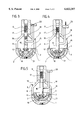
- FIG. 3 a longitudinal view in section of a modified instrument for releasing a joint insert with a suction holder for the joint insert before the suction holder is applied to the joint insert;
- FIG. 4 a view similar to FIG. 3 with the suction holder fixed on the joint insert;
- FIG. 5 a view similar to FIG. 4 after release of the joint insert from the joint socket.
- FIG. 1 shows a metallic joint socket 1 in which a ceramic joint insert 2 is inserted.
- the joint insert 2 is held in the joint socket 1 by a cone-type press fit.
- the joint socket 1 terminates in an edge 3 surrounding the joint insert 2, and circular recesses 4 arranged in the edge 3 are offset by 60° in relation to one another in the circumferential direction.
- a surgical instrument 5 is used for releasing the joint insert 2 from the joint socket 1.
- the surgical instrument 5 comprises a central shaft 6 with a handle 7 arranged thereon.
- three supports 9 are held at an enlargement 8 of the shaft 6.
- the supports 9 first have sections 10 extending outwardly at an incline from the axis of the shaft 6 and adjoining sections 11 extending parallel to the shaft 6.
- the supports 9 taper to a point.
- the three supports 9 are offset by 120° in the circumferential direction and are of such dimensions that the pointed free ends 12 can be inserted into three of the six recesses 4 in the edge 3 of the joint socket 1.
- the rear end of the handle 7, which is designed as a striking surface 13 can be struck with a suitable tool 14, for example, a hammer, so these blows are transmitted via the instrument 5 onto the joint socket 1.
- a suitable tool 14 for example, a hammer
- the supports 9 form above the inside space of the joint socket 1 a collecting space 15 in which the released joint insert 2 is captured in such a way that it cannot get lost, and the surgeon can then remove this joint insert 2 in a controlled manner by taking the instrument 5 off the joint socket 1.
- FIGS. 3 to 5 The instrument shown partially in FIGS. 3 to 5 is of essentially the same design as the instrument of FIGS. 1 and 2, and like parts are, therefore, given like reference numerals.
- a piston 16 is mounted for longitudinal displacement in the shaft 6 of this instrument 5.
- a helical spring 17 surrounding the piston 16 the piston 16 can be pushed into the shaft 6 and pulled out of it against the action of this spring.
- the depth to which the piston 16 can be pushed in is limited by a step 18 which strikes the underside of the shaft 6.
- the piston 16 protrudes into the collecting space 15 formed by the supports 9 and carries at its free end a sucker 19 which projects into the inside space of the joint insert 2.
- a handle 20 Protruding from the side of the piston 16 is a handle 20 which is guided through between two adjacent supports 9 so the piston 16 can be pushed in the direction of the arrow in FIG. 4 against the action of the helical spring 17 by pressure on this handle 20.
- the sucker 19 places itself on the joint surface 21 of the joint insert 2 and attaches itself thereto by suction so the piston 16 remains in the pulled out position and is held therein against the action of the helical spring 17 (FIG. 4).
- the helical spring 17 can, however, push the piston 16 into the shaft 6 again, and the joint insert 2 held via the sucker 19 is thereby lifted out of the joint socket 1 (FIG. 5).
- the surgeon recognizes release of the joint insert 2 from the joint socket 1 by movement of the handle 20 and, after this release of the connection, can remove the instrument 5 with the joint insert 2 held on the sucker 19 from the joint socket 1.
Abstract
A surgical instrument for releasing the press fit of a joint insert in a joint socket is characterized by at least two supports which are positionable on the edge of the joint socket and are connected to a striking surface which is arranged centrally in relation to the joint socket and is oriented away from the open side of the joint socket.
Description
The invention relates to a surgical instrument for releasing the press fit of a joint insert in a joint socket.
Joint inserts are often held by a cone-type press fit in joint sockets, for example, in hip joint sockets. In order to release such joint inserts from the joint socket again, it is either necessary to destroy the joint inserts or to provide special devices on the joint socket which enable ejection of the joint insert from the joint socket. For example, DE 295 16 473 U1 describes a screw arrangement on the joint socket with which the joint insert can be pressed out of the joint socket. However, this makes it necessary for the joint socket to be of appropriate design and for an opening to be left in the joint insert.
The object of the invention is to provide a surgical instrument by means of which the press fit between joint insert and joint socket can be released without any necessity for special structural configurations of the joint insert and the joint socket.
This object is accomplished in accordance with the invention by a surgical instrument of the generic kind which is characterized by at least two supports which are positionable on the edge of the joint socket and are connected to a striking surface which is arranged centrally in relation to the joint socket and is oriented away from the open side of the joint socket.
These supports are placed at the edge of the joint socket and blows are transmitted from the striking surface onto the joint socket via the supports. These blows can be executed by hand with a hammer or with a pneumatically or electrically operated striking tool of a type known per se.
It is known that cone-type press fits can be released under the effect of such blows, and precisely this is to be observed when the described surgical instrument is used. It is of advantage that at least two supports are provided and that the forces are introduced centrally so there is no danger of the joint socket tilting due to it being acted upon on one side or of it deviating under the blows.
In particular, it is expedient for three supports each offset in relation to one another by 120° to be provided, as it is then also ensured that the forces will be introduced precisely in a central direction.
In accordance with a preferred embodiment, provision is made for the supports to form a collecting space for the released insert. At their free end, the supports start at the edge of the joint socket and jointly form a collecting space or cage into which the released joint insert can drop, and so this joint insert is also fixed in its position after release from the instrument and can be removed from this position in a controlled manner by the surgeon.
It is expedient for the supports to have free ends which are insertable into receiving holes at the edge of the joint socket. For example, the supports can be pointed at the free end thereof, and these points can then be inserted into corresponding recesses at the edge of the joint socket so as to ensure a defined positioning of the surgical instrument relative to the joint socket.
In accordance with a preferred embodiment, provision is made for the supports to have sections extending perpendicularly to the plane formed by the edge of the joint socket and adjoining sections oriented towards the center axis of the joint socket. In this way, the supports form the described collecting space for the joint insert and also provide the surgeon with an unimpeded view of the joint socket.
It is advantageous for the supports to be connected to a central shaft which carries the striking surface at its end facing away from the supports. The shaft is preferably surrounded by a handle surface.
In accordance with a preferred embodiment, provision is made for the instrument to comprise a suction holder for the joint insert and for the suction holder to be displaceable in the direction towards the joint socket. This suction holder is fixed by suction on the joint surface of the joint insert and makes it possible for the joint insert which has been released by blows to be subsequently removed from the joint socket. It is expedient for the suction holder to be displaceable in the direction towards the joint socket against the action of a spring. For, once the joint insert is released from the joint socket such a suction holder can lift the joint insert out of the joint socket under the action of the spring.
The suction holder can, for example, carry a sucker.
It is also possible for a device for generating a vacuum, for example, a pump, to be associated with the suction holder, and for the suction holder to thereby adhere by suction to the joint surface of the joint insert.
It is advantageous for the suction holder to have a handle for displacement thereof. With this handle, the surgeon can move the suction holder into an engagement position on the joint insert. Once the joint insert is released, the surgeon recognizes by the movement of this handle, which the suction holder executes under the influence of the action of the spring, that the joint insert is released from the joint socket.
A particularly expedient arrangement is obtained by the suction holder being arranged in the central shaft of the instrument.
In accordance with a preferred embodiment, provision may be made for the striking surface to be designed as a connection piece for a mechanically operated striking tool. This can be, for example, a pneumatically or electrically operated striking tool which is connected at the striking surface to the instrument such that blows generated by the striking tool are transmitted to the instrument. In this context, the term "striking surface" is, therefore, to be understood as including, on the one hand, a surface which a hammer or a similar tool strikes, and, on the other hand, also a part of the instrument which receives and transmits blows generated by a striking tool into the instrument.
The following description of preferred embodiments of the invention taken in conjunction with the drawings serves for further explanation. The drawings show:
FIG. 1 a side view of a surgical instrument after it has been placed on the edge of a joint socket;
FIG. 2 a plan view of the joint socket of FIG. 1 with the surgical instrument placed thereon;
FIG. 3 a longitudinal view in section of a modified instrument for releasing a joint insert with a suction holder for the joint insert before the suction holder is applied to the joint insert;
FIG. 4 a view similar to FIG. 3 with the suction holder fixed on the joint insert; and
FIG. 5 a view similar to FIG. 4 after release of the joint insert from the joint socket.
FIG. 1 shows a metallic joint socket 1 in which a ceramic joint insert 2 is inserted. The joint insert 2 is held in the joint socket 1 by a cone-type press fit.
At the open end, the joint socket 1 terminates in an edge 3 surrounding the joint insert 2, and circular recesses 4 arranged in the edge 3 are offset by 60° in relation to one another in the circumferential direction.
A surgical instrument 5 is used for releasing the joint insert 2 from the joint socket 1. The surgical instrument 5 comprises a central shaft 6 with a handle 7 arranged thereon. At the free end of the instrument, three supports 9 are held at an enlargement 8 of the shaft 6. The supports 9 first have sections 10 extending outwardly at an incline from the axis of the shaft 6 and adjoining sections 11 extending parallel to the shaft 6. At the free end 12, the supports 9 taper to a point. The three supports 9 are offset by 120° in the circumferential direction and are of such dimensions that the pointed free ends 12 can be inserted into three of the six recesses 4 in the edge 3 of the joint socket 1.
In this position, which is shown in FIG. 1, the shaft 6 is in alignment with the center axis of the joint socket 1.
In this position, the rear end of the handle 7, which is designed as a striking surface 13, can be struck with a suitable tool 14, for example, a hammer, so these blows are transmitted via the instrument 5 onto the joint socket 1. These blows bring about a loosening of the joint insert 2 from the joint socket 1, i.e., the press fit between these two parts is released.
The supports 9 form above the inside space of the joint socket 1 a collecting space 15 in which the released joint insert 2 is captured in such a way that it cannot get lost, and the surgeon can then remove this joint insert 2 in a controlled manner by taking the instrument 5 off the joint socket 1.
The instrument shown partially in FIGS. 3 to 5 is of essentially the same design as the instrument of FIGS. 1 and 2, and like parts are, therefore, given like reference numerals.
In addition to the features shown in FIGS. 1 and 2, a piston 16 is mounted for longitudinal displacement in the shaft 6 of this instrument 5. By means of a helical spring 17 surrounding the piston 16, the piston 16 can be pushed into the shaft 6 and pulled out of it against the action of this spring. The depth to which the piston 16 can be pushed in is limited by a step 18 which strikes the underside of the shaft 6.
The piston 16 protrudes into the collecting space 15 formed by the supports 9 and carries at its free end a sucker 19 which projects into the inside space of the joint insert 2.
Protruding from the side of the piston 16 is a handle 20 which is guided through between two adjacent supports 9 so the piston 16 can be pushed in the direction of the arrow in FIG. 4 against the action of the helical spring 17 by pressure on this handle 20. During this movement, the sucker 19 places itself on the joint surface 21 of the joint insert 2 and attaches itself thereto by suction so the piston 16 remains in the pulled out position and is held therein against the action of the helical spring 17 (FIG. 4).
Once the joint insert 2 is released from the joint socket 1 by the blows on the instrument 5 in the described manner, the helical spring 17 can, however, push the piston 16 into the shaft 6 again, and the joint insert 2 held via the sucker 19 is thereby lifted out of the joint socket 1 (FIG. 5). The surgeon recognizes release of the joint insert 2 from the joint socket 1 by movement of the handle 20 and, after this release of the connection, can remove the instrument 5 with the joint insert 2 held on the sucker 19 from the joint socket 1.
Claims (16)
1. A surgical instrument comprising:
at least two supports adapted to be positioned on an edge of a joint socket for releasing the press fit of a joint insert in said joint socket;
said supports being movably connected via a shaft to a striking surface arranged centrally in relation to said joint socket when said supports are positioned on the edge of the joint socket; and
said striking surface being oriented away from an open side of said joint socket; wherein a force applied to said striking surface is transmitted to said support via said shaft.
2. A surgical instrument as defined in claim 1 comprising three supports offset in relation to one another by 120°.
3. A surgical instrument as defined in claim 2 wherein said supports form a collecting space for said joint insert when released.
4. A surgical instrument as defined in claim 1 wherein said supports have free ends that are adapted to be inserted into corresponding receiving holes at the edge of said joint socket.
5. A surgical instrument as defined in claim 1 wherein said supports have:
sections extending perpendicularly to a plane formed by the edge of said joint socket, and
adjoining sections oriented towards a center axis of said joint socket.
6. A surgical instrument as defined in claim 1 wherein said shaft comprises a central shaft carrying said striking surface at an end facing away from said supports.
7. A surgical instrument as defined in claim 6 wherein at least a portion of said central shaft is surrounded by a handle surface.
8. A surgical instrument as defined in claim 6 further comprising a suction holder for said joint insert, said suction holder being displaceable in a direction towards the joint socket.
9. A surgical instrument as defined in claim 1 further comprising a suction holder for said joint insert, said suction holder being displaceable in a direction towards the joint socket.
10. A surgical instrument as defined in claim 9 wherein said suction holder is displaceable in said direction towards said joint socket against the action of a spring.
11. A surgical instrument as defined in claim 10 wherein said suction holder carries a sucker.
12. A surgical instrument as defined in claim 9 further comprising a device for generating a vacuum associated with said suction holder.
13. A surgical instrument as defined in claim 9 wherein said suction holder has a handle for displacement thereof.
14. A surgical instrument as defined in claim 9 wherein said suction holder is arranged in a central shaft of the surgical instrument.
15. A surgical instrument as defined in claim 1 wherein said striking surface is designed as a connection piece for a mechanically operated striking tool.
16. A surgical instrument as defined in claim 1 wherein said striking surface comprises a solid striking shaft for transmitting a striking force from a striking tool to said joint socket via said supports.
Applications Claiming Priority (2)
| Application Number | Priority Date | Filing Date | Title |
|---|---|---|---|
| DE19708604A DE19708604C1 (en) | 1997-03-03 | 1997-03-03 | Surgical instrument for removal of limb joint insert from recess |
| DE19708604.7 | 1997-03-03 |
Publications (1)
| Publication Number | Publication Date |
|---|---|
| US6022357A true US6022357A (en) | 2000-02-08 |
Family
ID=7822085
Family Applications (1)
| Application Number | Title | Priority Date | Filing Date |
|---|---|---|---|
| US09/032,233 Expired - Fee Related US6022357A (en) | 1997-03-03 | 1998-02-27 | Surgical instrument |
Country Status (1)
| Country | Link |
|---|---|
| US (1) | US6022357A (en) |
Cited By (42)
| Publication number | Priority date | Publication date | Assignee | Title |
|---|---|---|---|---|
| US20020177854A1 (en) * | 1997-03-14 | 2002-11-28 | Finsbury (Development) Limited | Prosthetic implant and surgical tool |
| US6565575B2 (en) * | 2001-02-16 | 2003-05-20 | Randall J. Lewis | Method and apparatus for removing an acetabular cup |
| US6589284B1 (en) * | 1999-06-14 | 2003-07-08 | Ceramtec Ag | Modular socket for a ball joint prosthesis |
| US6656190B2 (en) * | 2000-03-15 | 2003-12-02 | Spinevision S. A. | Implant prehension device |
| US6679888B2 (en) | 2001-05-29 | 2004-01-20 | Synthes | Femur lever |
| US6682567B1 (en) * | 2001-09-19 | 2004-01-27 | Biomet, Inc. | Method and apparatus for providing a shell component incorporating a porous ingrowth material and liner |
| US6709439B2 (en) | 2001-10-30 | 2004-03-23 | Depuy Spine, Inc. | Slaphammer tool |
| US20040186586A1 (en) * | 2003-02-04 | 2004-09-23 | Seyer Steven F. | Acetabular component insertion and extraction tool for use therewith, and method of locking an acetabular component to an insertion and extraction tool |
| US20040215200A1 (en) * | 2003-01-17 | 2004-10-28 | Alain Tornier | Ancillary tool and method for positioning a prosthetic acetabulum of a hip prosthesis |
| US6814738B2 (en) | 2001-01-23 | 2004-11-09 | Depuy Acromed, Inc. | Medical impacting device and system |
| US20050171545A1 (en) * | 2004-01-30 | 2005-08-04 | Howmedica Osteonics Corp. | Knee computer-aided navigation instruments |
| US20050228395A1 (en) * | 2004-03-05 | 2005-10-13 | Benoist Girard Sas | Prosthetic acetabular cup inserter |
| US20050228394A1 (en) * | 2004-03-31 | 2005-10-13 | Diane Bihary | Suction inserter |
| FR2879916A1 (en) * | 2004-12-29 | 2006-06-30 | Patrice Gestraud | Hip prosthesis for human being, has spacer to integrate eyelet with acetabulum, and fixation screw cooperating with eyelet`s opening and having stem, threading for step and another threading formed between shoulder head and determined point |
| US20060195105A1 (en) * | 2005-01-28 | 2006-08-31 | Teeny Steven M | Acetabular shell removal tool |
| US20060200165A1 (en) * | 2005-03-01 | 2006-09-07 | Howmedia Osteonics Corp. | Acetabular shell removal instrument |
| US20060293686A1 (en) * | 2005-05-12 | 2006-12-28 | Finsbury (Development) Limited | Cap and activation tool |
| US20070219562A1 (en) * | 2006-03-17 | 2007-09-20 | Biomet Manufacturing Corp. | Method and apparatus for implanting a prosthesis |
| US20070276400A1 (en) * | 2003-09-22 | 2007-11-29 | Gary Moore | Drill Guide Assembly |
| US20080041889A1 (en) * | 2006-08-17 | 2008-02-21 | Coster Tecnologie Speciali S.P.A. | Lockable spray cap |
| FR2911062A1 (en) * | 2007-01-08 | 2008-07-11 | Thomas Gradel | Acetabular cup for replacing natural acetabulum of hip, has insertion cup with receiving peripheral structure to receive fixation unit, where fixation unit fixes nails impactor fixed at acetabular cup |
| US20080228188A1 (en) * | 2005-03-22 | 2008-09-18 | Alec Paul Birkbeck | Surgical guide |
| US20100087930A1 (en) * | 2008-10-07 | 2010-04-08 | Finsbury (Development) Limited | Prosthesis |
| US20100131073A1 (en) * | 2008-11-24 | 2010-05-27 | Biomet Manufacturing Corp. | Multiple Bearing Acetabular Prosthesis |
| US20100285897A1 (en) * | 2009-05-11 | 2010-11-11 | Hiroyuki Takeuchi | Golf club shaft |
| US20100318192A1 (en) * | 2009-06-10 | 2010-12-16 | Laffay Jean-Pierre | Acetabular prosthetic system with simplified impaction |
| US20110218582A1 (en) * | 2010-03-05 | 2011-09-08 | Biomet Manufacturing Corp. | Method and Apparatus for Implanting a Modular Femoral Hip |
| US20110218537A1 (en) * | 2010-03-05 | 2011-09-08 | Biomet Manufacturing Corp. | Method and Apparatus for Preparing a Proximal Femur |
| US20110218583A1 (en) * | 2010-03-05 | 2011-09-08 | Biomet Manufacturing Corp. | Assembly Tool for Modular Implants and Associated Method |
| US20110218640A1 (en) * | 2010-03-05 | 2011-09-08 | Biomet Manufacturing Corp. | Method and Apparatus for Trialing and Implanting a Modular Femoral Hip |
| US20110218636A1 (en) * | 2010-03-05 | 2011-09-08 | Biomet Manufacturing Corp. | Guide Assembly for Lateral Implants and Associated Methods |
| US20110218641A1 (en) * | 2010-03-05 | 2011-09-08 | Biomet Manufacturing Corp. | Modular Lateral Hip Augments |
| US8308810B2 (en) | 2009-07-14 | 2012-11-13 | Biomet Manufacturing Corp. | Multiple bearing acetabular prosthesis |
| US8834480B2 (en) | 2011-01-17 | 2014-09-16 | Zimmer, Inc. | Adapter for explant system |
| US20150094728A1 (en) * | 2013-09-30 | 2015-04-02 | DePuy Synthes Products, LLC | Instrument for positioning a cup component of an orthopaedic joint prosthesis |
| US20160045319A1 (en) * | 2014-08-13 | 2016-02-18 | Derek James Wallace McMinn | Acetabular cup prosthesis |
| US10405991B2 (en) | 2013-09-30 | 2019-09-10 | Depuy Ireland Unlimited Company | Instrument for positioning a cup component of an orthopaedic joint prosthesis |
| CN110461266A (en) * | 2016-11-15 | 2019-11-15 | 辰维医疗科技有限公司 | Alignment guide and application method for acetabular bone implant surgery |
| AU2018204909B2 (en) * | 2015-01-08 | 2019-11-21 | Medacta International Sa | Joint prosthesis with removal device |
| WO2019246523A1 (en) * | 2018-06-22 | 2019-12-26 | Zimmer, Inc. | Acetabular liner extraction |
| US10588756B2 (en) | 2017-03-31 | 2020-03-17 | DePuy Synthes Products, Inc. | System and method for implanting an acetabular prosthetic component |
| US10596011B2 (en) | 2018-01-31 | 2020-03-24 | Depuy Ireland Unlimited Company | Orthopaedic surgical instrument and method for positioning an acetabular prosthetic component |
Citations (8)
| Publication number | Priority date | Publication date | Assignee | Title |
|---|---|---|---|---|
| US2002021A (en) * | 1934-02-27 | 1935-05-21 | Rouse Howard | Surgical fracture extension appliance |
| US4896663A (en) * | 1988-10-14 | 1990-01-30 | Boehringer Mannheim Corporation | Self centering femoral drill jig |
| US5141512A (en) * | 1989-08-28 | 1992-08-25 | Farmer Malcolm H | Alignment of hip joint sockets in hip joint replacement |
| US5330481A (en) * | 1989-01-31 | 1994-07-19 | Advanced Osseous Technologies, Inc. | Apparatus for implantation and extraction of osteal prostheses |
| US5417693A (en) * | 1992-06-17 | 1995-05-23 | Minnesota Mining And Manufacturing Company | Instrumentation for preparing the femur for an artificial knee implant and for positioning the femoral component of the implant |
| DE29516473U1 (en) * | 1995-10-17 | 1995-12-07 | Keramed Medizintechnik Gmbh | Artificial acetabular cup |
| US5505738A (en) * | 1993-01-12 | 1996-04-09 | Howmedica Gmbh | Surgical saw |
| US5817098A (en) * | 1995-05-17 | 1998-10-06 | Astra Aktiebolag | Drill guide instrument |
-
1998
- 1998-02-27 US US09/032,233 patent/US6022357A/en not_active Expired - Fee Related
Patent Citations (8)
| Publication number | Priority date | Publication date | Assignee | Title |
|---|---|---|---|---|
| US2002021A (en) * | 1934-02-27 | 1935-05-21 | Rouse Howard | Surgical fracture extension appliance |
| US4896663A (en) * | 1988-10-14 | 1990-01-30 | Boehringer Mannheim Corporation | Self centering femoral drill jig |
| US5330481A (en) * | 1989-01-31 | 1994-07-19 | Advanced Osseous Technologies, Inc. | Apparatus for implantation and extraction of osteal prostheses |
| US5141512A (en) * | 1989-08-28 | 1992-08-25 | Farmer Malcolm H | Alignment of hip joint sockets in hip joint replacement |
| US5417693A (en) * | 1992-06-17 | 1995-05-23 | Minnesota Mining And Manufacturing Company | Instrumentation for preparing the femur for an artificial knee implant and for positioning the femoral component of the implant |
| US5505738A (en) * | 1993-01-12 | 1996-04-09 | Howmedica Gmbh | Surgical saw |
| US5817098A (en) * | 1995-05-17 | 1998-10-06 | Astra Aktiebolag | Drill guide instrument |
| DE29516473U1 (en) * | 1995-10-17 | 1995-12-07 | Keramed Medizintechnik Gmbh | Artificial acetabular cup |
Cited By (94)
| Publication number | Priority date | Publication date | Assignee | Title |
|---|---|---|---|---|
| US6746452B2 (en) * | 1997-03-14 | 2004-06-08 | Finsbury (Development) Limited | Prosthetic implant and surgical tool |
| US20020177854A1 (en) * | 1997-03-14 | 2002-11-28 | Finsbury (Development) Limited | Prosthetic implant and surgical tool |
| US6589284B1 (en) * | 1999-06-14 | 2003-07-08 | Ceramtec Ag | Modular socket for a ball joint prosthesis |
| US6656190B2 (en) * | 2000-03-15 | 2003-12-02 | Spinevision S. A. | Implant prehension device |
| US6814738B2 (en) | 2001-01-23 | 2004-11-09 | Depuy Acromed, Inc. | Medical impacting device and system |
| US6565575B2 (en) * | 2001-02-16 | 2003-05-20 | Randall J. Lewis | Method and apparatus for removing an acetabular cup |
| US6679888B2 (en) | 2001-05-29 | 2004-01-20 | Synthes | Femur lever |
| US6682567B1 (en) * | 2001-09-19 | 2004-01-27 | Biomet, Inc. | Method and apparatus for providing a shell component incorporating a porous ingrowth material and liner |
| US6709439B2 (en) | 2001-10-30 | 2004-03-23 | Depuy Spine, Inc. | Slaphammer tool |
| US8821503B2 (en) | 2003-01-17 | 2014-09-02 | Tornier Sas | Ancillary tool and method for positioning a prosthetic acetabulum of a hip prosthesis |
| US20040215200A1 (en) * | 2003-01-17 | 2004-10-28 | Alain Tornier | Ancillary tool and method for positioning a prosthetic acetabulum of a hip prosthesis |
| US20080255568A1 (en) * | 2003-01-17 | 2008-10-16 | Tornier | Ancillary tool and method for positioning a prosthetic acetabulum of a hip prosthesis |
| US7396357B2 (en) * | 2003-01-17 | 2008-07-08 | Tornier Sas | Ancillary tool and method for positioning a prosthetic acetabulum of a hip prosthesis |
| US20040186586A1 (en) * | 2003-02-04 | 2004-09-23 | Seyer Steven F. | Acetabular component insertion and extraction tool for use therewith, and method of locking an acetabular component to an insertion and extraction tool |
| US7344565B2 (en) * | 2003-02-04 | 2008-03-18 | Wright Medical Technology, Inc. | Acetabular component insertion and extraction tool for use therewith, and method of locking an acetabular component to an insertion and extraction tool |
| US20070276400A1 (en) * | 2003-09-22 | 2007-11-29 | Gary Moore | Drill Guide Assembly |
| US20050171545A1 (en) * | 2004-01-30 | 2005-08-04 | Howmedica Osteonics Corp. | Knee computer-aided navigation instruments |
| US20050228395A1 (en) * | 2004-03-05 | 2005-10-13 | Benoist Girard Sas | Prosthetic acetabular cup inserter |
| US7341593B2 (en) * | 2004-03-05 | 2008-03-11 | Benoist Girard Sas | Prosthetic acetabular cup inserter |
| US20050228394A1 (en) * | 2004-03-31 | 2005-10-13 | Diane Bihary | Suction inserter |
| FR2879916A1 (en) * | 2004-12-29 | 2006-06-30 | Patrice Gestraud | Hip prosthesis for human being, has spacer to integrate eyelet with acetabulum, and fixation screw cooperating with eyelet`s opening and having stem, threading for step and another threading formed between shoulder head and determined point |
| US7942883B2 (en) | 2005-01-28 | 2011-05-17 | Teeny Steven M | Acetabular shell removal tool |
| US20100262155A1 (en) * | 2005-01-28 | 2010-10-14 | Steven M. Teeny | Acetabular shell removal tool |
| US7744602B2 (en) * | 2005-01-28 | 2010-06-29 | Steven M. Teeny | Acetabular shell removal tool |
| US20060195105A1 (en) * | 2005-01-28 | 2006-08-31 | Teeny Steven M | Acetabular shell removal tool |
| US8475465B2 (en) | 2005-01-28 | 2013-07-02 | Steven M. Teeny | Acetabular shell removal tool |
| US20110166577A1 (en) * | 2005-01-28 | 2011-07-07 | Teeny Steven M | Acetabular shell removal tool |
| US8034059B2 (en) | 2005-03-01 | 2011-10-11 | Howmedica Osteonics Corp. | Acetabular shell removal instrument |
| US7763031B2 (en) | 2005-03-01 | 2010-07-27 | Howmedica Osteonics Corp. | Acetabular shell removal instrument |
| US20100228259A1 (en) * | 2005-03-01 | 2010-09-09 | Howmedica Osteonics Corp. | Acetabular shell removal instrument |
| US20060200165A1 (en) * | 2005-03-01 | 2006-09-07 | Howmedia Osteonics Corp. | Acetabular shell removal instrument |
| US20080228188A1 (en) * | 2005-03-22 | 2008-09-18 | Alec Paul Birkbeck | Surgical guide |
| US20060293686A1 (en) * | 2005-05-12 | 2006-12-28 | Finsbury (Development) Limited | Cap and activation tool |
| US8500744B2 (en) | 2005-05-12 | 2013-08-06 | Finsbury (Development) Limited | Cap and activation tool |
| US7727282B2 (en) * | 2006-03-17 | 2010-06-01 | Biomet Manufacturing Corp. | Method and apparatus for implanting a prosthesis |
| US20070219562A1 (en) * | 2006-03-17 | 2007-09-20 | Biomet Manufacturing Corp. | Method and apparatus for implanting a prosthesis |
| US8418892B2 (en) | 2006-08-17 | 2013-04-16 | Coster Tecnologie Speciali S.P.A. | Lockable spray cap |
| US20080041889A1 (en) * | 2006-08-17 | 2008-02-21 | Coster Tecnologie Speciali S.P.A. | Lockable spray cap |
| FR2911062A1 (en) * | 2007-01-08 | 2008-07-11 | Thomas Gradel | Acetabular cup for replacing natural acetabulum of hip, has insertion cup with receiving peripheral structure to receive fixation unit, where fixation unit fixes nails impactor fixed at acetabular cup |
| US20100306987A1 (en) * | 2007-01-08 | 2010-12-09 | Thomas Gradel | Cotyle comprising a sterile interface |
| US8764843B2 (en) | 2007-01-08 | 2014-07-01 | Thomas Gradel | Cotyle comprising a sterile interface |
| US20100063597A1 (en) * | 2007-01-08 | 2010-03-11 | Thomas Gradel | Cotyle comprising a sterile interface |
| US8845748B2 (en) | 2007-01-08 | 2014-09-30 | Thomas Gradel | Cotyle comprising a sterile interface |
| RU2453293C2 (en) * | 2007-01-08 | 2012-06-20 | Тома ГРАДЕЛЬ | Cotyloid cavity with sterile boundary surface |
| CN101600403B (en) * | 2007-01-08 | 2011-11-30 | 托马斯·格拉德尔 | Cotyle comprising a sterile interface |
| WO2008135868A1 (en) * | 2007-01-08 | 2008-11-13 | Thomas Gradel | Cotyle comprising a sterile interface |
| US9168143B2 (en) | 2007-01-08 | 2015-10-27 | Thomas Gradel | Cotyle comprising a sterile interface |
| EP2174621A1 (en) | 2008-10-07 | 2010-04-14 | Finsbury (Development) Limited | Prosthesis |
| US9339389B2 (en) | 2008-10-07 | 2016-05-17 | Finsbury (Development) Limited | Acetabular cup prosthesis and method of forming the prosthesis |
| US8372155B2 (en) | 2008-10-07 | 2013-02-12 | Finsbury (Development) Limited | Acetabular cup prosthesis and method of forming the prosthesis |
| EP2174621B1 (en) * | 2008-10-07 | 2013-07-17 | Finsbury (Development) Limited | Prosthesis |
| US20100087930A1 (en) * | 2008-10-07 | 2010-04-08 | Finsbury (Development) Limited | Prosthesis |
| US9445903B2 (en) | 2008-11-24 | 2016-09-20 | Biomet Manufacturing, Llc | Multi-bearing acetabular prosthesis |
| US8123815B2 (en) | 2008-11-24 | 2012-02-28 | Biomet Manufacturing Corp. | Multiple bearing acetabular prosthesis |
| US20100131073A1 (en) * | 2008-11-24 | 2010-05-27 | Biomet Manufacturing Corp. | Multiple Bearing Acetabular Prosthesis |
| US20100285897A1 (en) * | 2009-05-11 | 2010-11-11 | Hiroyuki Takeuchi | Golf club shaft |
| US10420648B2 (en) * | 2009-06-10 | 2019-09-24 | Jean-Pierre LAFFAY | Acetabular prosthetic system with simplified impaction |
| US20100318192A1 (en) * | 2009-06-10 | 2010-12-16 | Laffay Jean-Pierre | Acetabular prosthetic system with simplified impaction |
| US9445904B2 (en) | 2009-07-14 | 2016-09-20 | Biomet Manufacturing, Llc | Multiple bearing acetabular prosthesis |
| US8308810B2 (en) | 2009-07-14 | 2012-11-13 | Biomet Manufacturing Corp. | Multiple bearing acetabular prosthesis |
| US20110218636A1 (en) * | 2010-03-05 | 2011-09-08 | Biomet Manufacturing Corp. | Guide Assembly for Lateral Implants and Associated Methods |
| US9339318B2 (en) | 2010-03-05 | 2016-05-17 | Biomet Manufacturing, Llc | Method and apparatus for preparing a proximal femur |
| US8529569B2 (en) | 2010-03-05 | 2013-09-10 | Biomet Manufacturing, Llc | Method and apparatus for preparing a proximal femur |
| US8591518B2 (en) | 2010-03-05 | 2013-11-26 | Biomet Manufacturing, Llc | Method and apparatus for implanting a modular femoral hip |
| US8679130B2 (en) | 2010-03-05 | 2014-03-25 | Biomet Manufacturing, Llc | Guide assembly for lateral implants and associated methods |
| US8419743B2 (en) | 2010-03-05 | 2013-04-16 | Biomet Manufacturing Corp. | Assembly tool for modular implants and associated method |
| US8333807B2 (en) | 2010-03-05 | 2012-12-18 | Biomet Manufacturing Corp. | Method and apparatus for trialing and implanting a modular femoral hip |
| US20110218582A1 (en) * | 2010-03-05 | 2011-09-08 | Biomet Manufacturing Corp. | Method and Apparatus for Implanting a Modular Femoral Hip |
| US8221432B2 (en) | 2010-03-05 | 2012-07-17 | Biomet Manufacturing Corp. | Method and apparatus for implanting a modular femoral hip |
| US8876837B2 (en) | 2010-03-05 | 2014-11-04 | Biomet Manufacturing, Llc | Method and apparatus for implanting a modular femoral hip |
| US8906109B2 (en) | 2010-03-05 | 2014-12-09 | Biomet Manufacturing, Llc | Modular lateral hip augments |
| US10188520B2 (en) | 2010-03-05 | 2019-01-29 | Biomet Manufacturing, Llc | Modular lateral hip augments |
| US9138273B2 (en) | 2010-03-05 | 2015-09-22 | Biomet Manufacturing, Llc | Guide assembly for lateral implants and associated methods |
| US20110218641A1 (en) * | 2010-03-05 | 2011-09-08 | Biomet Manufacturing Corp. | Modular Lateral Hip Augments |
| US9615942B2 (en) | 2010-03-05 | 2017-04-11 | Biomet Manufacturing, Llc | Method and apparatus for trialing and implanting a modular femoral hip |
| US9314287B2 (en) | 2010-03-05 | 2016-04-19 | Biomet Manufacturing, Llc | Assembly tool for modular implant and associated method |
| US20110218640A1 (en) * | 2010-03-05 | 2011-09-08 | Biomet Manufacturing Corp. | Method and Apparatus for Trialing and Implanting a Modular Femoral Hip |
| US8460393B2 (en) | 2010-03-05 | 2013-06-11 | Biomet Manufacturing Corp. | Modular lateral hip augments |
| US20110218583A1 (en) * | 2010-03-05 | 2011-09-08 | Biomet Manufacturing Corp. | Assembly Tool for Modular Implants and Associated Method |
| US20110218537A1 (en) * | 2010-03-05 | 2011-09-08 | Biomet Manufacturing Corp. | Method and Apparatus for Preparing a Proximal Femur |
| US9510950B2 (en) | 2010-03-05 | 2016-12-06 | Biomet Manufacturing, Llc | Modular lateral hip auguments |
| US8834480B2 (en) | 2011-01-17 | 2014-09-16 | Zimmer, Inc. | Adapter for explant system |
| US20170020687A1 (en) * | 2013-09-30 | 2017-01-26 | DePuy Synthes Products, Inc. | Instrument for positioning a cup component of an orthopaedic joint prosthesis |
| US20150094728A1 (en) * | 2013-09-30 | 2015-04-02 | DePuy Synthes Products, LLC | Instrument for positioning a cup component of an orthopaedic joint prosthesis |
| US10405991B2 (en) | 2013-09-30 | 2019-09-10 | Depuy Ireland Unlimited Company | Instrument for positioning a cup component of an orthopaedic joint prosthesis |
| US20160045319A1 (en) * | 2014-08-13 | 2016-02-18 | Derek James Wallace McMinn | Acetabular cup prosthesis |
| AU2018204909B2 (en) * | 2015-01-08 | 2019-11-21 | Medacta International Sa | Joint prosthesis with removal device |
| US11096800B2 (en) | 2015-01-08 | 2021-08-24 | Medacta International Sa | Joint prosthesis with removal device |
| CN110461266A (en) * | 2016-11-15 | 2019-11-15 | 辰维医疗科技有限公司 | Alignment guide and application method for acetabular bone implant surgery |
| US10588756B2 (en) | 2017-03-31 | 2020-03-17 | DePuy Synthes Products, Inc. | System and method for implanting an acetabular prosthetic component |
| US10596011B2 (en) | 2018-01-31 | 2020-03-24 | Depuy Ireland Unlimited Company | Orthopaedic surgical instrument and method for positioning an acetabular prosthetic component |
| WO2019246523A1 (en) * | 2018-06-22 | 2019-12-26 | Zimmer, Inc. | Acetabular liner extraction |
| CN112334094A (en) * | 2018-06-22 | 2021-02-05 | 捷迈有限公司 | Acetabular liner extraction |
| US11452620B2 (en) | 2018-06-22 | 2022-09-27 | Zimmer, Inc. | Acetabular liner extraction |
Similar Documents
| Publication | Publication Date | Title |
|---|---|---|
| US6022357A (en) | Surgical instrument | |
| US6468281B1 (en) | Instrument for manipulating components of joint prostheses | |
| EP0954259B1 (en) | Automatic impact device | |
| US6066143A (en) | Pin puller | |
| EP1120087A3 (en) | Apparatus for affixing tissue repair material to bone | |
| EP3592254B1 (en) | Quick coupling apparatus on instrument handle | |
| AU708768B2 (en) | Bone anchor inserter, method for loading same, method for holding and delivering a bone anchor, and method for inserting a bone anchor in a bone | |
| JP5099521B2 (en) | Insertion device for an internal prosthesis with a prosthetic trunk inserted into the medullary cavity | |
| WO1999006192A3 (en) | Cutting insert cartridge arrangement | |
| EP1308143A3 (en) | Slaphammer tool | |
| GB2371492B (en) | Surgical tool mechanism | |
| ATE452605T1 (en) | HIP SOCKET INSERT EXTRACTION DEVICE AND KIT | |
| WO2002000345A3 (en) | Automatic pipette with tip identification and detipping mechanism | |
| WO2004050971A3 (en) | Apparatus and method for manipulating tissue | |
| CN108135704B (en) | Acetabular cup extractor | |
| WO2005097427A3 (en) | Stapler with detachable accessory | |
| EP1285731A3 (en) | Hold down toggle clamp | |
| JP2018525118A (en) | Surgical tray, instrument, and method for implanting a hip replacement | |
| WO2004075732A3 (en) | Tissue localizing and separating assembly | |
| GB2392625A (en) | Surgical cutting instrument | |
| JPH10151144A (en) | Driving appliance for nail or the like | |
| EP1136217A3 (en) | Quick release device for a tire mold plate | |
| US20180193169A1 (en) | Femoral cup and femoral ball extractor | |
| WO2003033855A3 (en) | Apparatus and methods for jarring | |
| JPH1170134A (en) | Device for freely detachably attaching work means to element or tool for operation |
Legal Events
| Date | Code | Title | Description |
|---|---|---|---|
| AS | Assignment |
Owner name: AESCULAP AG & CO. KG, GERMANY Free format text: ASSIGNMENT OF ASSIGNORS INTEREST;ASSIGNORS:REU, GERHARD;STROHM, JUERGEN;REEL/FRAME:009657/0533 Effective date: 19980408 |
|
| FPAY | Fee payment |
Year of fee payment: 4 |
|
| REMI | Maintenance fee reminder mailed | ||
| LAPS | Lapse for failure to pay maintenance fees | ||
| STCH | Information on status: patent discontinuation |
Free format text: PATENT EXPIRED DUE TO NONPAYMENT OF MAINTENANCE FEES UNDER 37 CFR 1.362 |
|
| FP | Lapsed due to failure to pay maintenance fee |
Effective date: 20080208 |