US6020561A - Printed circuit substrate with solder formed on pad-on-via and pad-off-via contacts thereof - Google Patents
Printed circuit substrate with solder formed on pad-on-via and pad-off-via contacts thereof Download PDFInfo
- Publication number
- US6020561A US6020561A US08/745,470 US74547096A US6020561A US 6020561 A US6020561 A US 6020561A US 74547096 A US74547096 A US 74547096A US 6020561 A US6020561 A US 6020561A
- Authority
- US
- United States
- Prior art keywords
- pad
- substrate
- printed circuit
- solder
- via contact
- Prior art date
- Legal status (The legal status is an assumption and is not a legal conclusion. Google has not performed a legal analysis and makes no representation as to the accuracy of the status listed.)
- Expired - Lifetime
Links
Images

Classifications
-
- H—ELECTRICITY
- H01—ELECTRIC ELEMENTS
- H01L—SEMICONDUCTOR DEVICES NOT COVERED BY CLASS H10
- H01L24/00—Arrangements for connecting or disconnecting semiconductor or solid-state bodies; Methods or apparatus related thereto
- H01L24/80—Methods for connecting semiconductor or other solid state bodies using means for bonding being attached to, or being formed on, the surface to be connected
- H01L24/81—Methods for connecting semiconductor or other solid state bodies using means for bonding being attached to, or being formed on, the surface to be connected using a bump connector
-
- H—ELECTRICITY
- H01—ELECTRIC ELEMENTS
- H01L—SEMICONDUCTOR DEVICES NOT COVERED BY CLASS H10
- H01L21/00—Processes or apparatus adapted for the manufacture or treatment of semiconductor or solid state devices or of parts thereof
- H01L21/02—Manufacture or treatment of semiconductor devices or of parts thereof
- H01L21/04—Manufacture or treatment of semiconductor devices or of parts thereof the devices having at least one potential-jump barrier or surface barrier, e.g. PN junction, depletion layer or carrier concentration layer
- H01L21/48—Manufacture or treatment of parts, e.g. containers, prior to assembly of the devices, using processes not provided for in a single one of the subgroups H01L21/06 - H01L21/326
- H01L21/4814—Conductive parts
- H01L21/4846—Leads on or in insulating or insulated substrates, e.g. metallisation
- H01L21/4853—Connection or disconnection of other leads to or from a metallisation, e.g. pins, wires, bumps
-
- H—ELECTRICITY
- H01—ELECTRIC ELEMENTS
- H01L—SEMICONDUCTOR DEVICES NOT COVERED BY CLASS H10
- H01L23/00—Details of semiconductor or other solid state devices
- H01L23/48—Arrangements for conducting electric current to or from the solid state body in operation, e.g. leads, terminal arrangements ; Selection of materials therefor
- H01L23/488—Arrangements for conducting electric current to or from the solid state body in operation, e.g. leads, terminal arrangements ; Selection of materials therefor consisting of soldered or bonded constructions
- H01L23/498—Leads, i.e. metallisations or lead-frames on insulating substrates, e.g. chip carriers
- H01L23/49811—Additional leads joined to the metallisation on the insulating substrate, e.g. pins, bumps, wires, flat leads
-
- H—ELECTRICITY
- H01—ELECTRIC ELEMENTS
- H01L—SEMICONDUCTOR DEVICES NOT COVERED BY CLASS H10
- H01L23/00—Details of semiconductor or other solid state devices
- H01L23/48—Arrangements for conducting electric current to or from the solid state body in operation, e.g. leads, terminal arrangements ; Selection of materials therefor
- H01L23/488—Arrangements for conducting electric current to or from the solid state body in operation, e.g. leads, terminal arrangements ; Selection of materials therefor consisting of soldered or bonded constructions
- H01L23/498—Leads, i.e. metallisations or lead-frames on insulating substrates, e.g. chip carriers
- H01L23/49866—Leads, i.e. metallisations or lead-frames on insulating substrates, e.g. chip carriers characterised by the materials
- H01L23/49894—Materials of the insulating layers or coatings
-
- H—ELECTRICITY
- H01—ELECTRIC ELEMENTS
- H01L—SEMICONDUCTOR DEVICES NOT COVERED BY CLASS H10
- H01L24/00—Arrangements for connecting or disconnecting semiconductor or solid-state bodies; Methods or apparatus related thereto
- H01L24/01—Means for bonding being attached to, or being formed on, the surface to be connected, e.g. chip-to-package, die-attach, "first-level" interconnects; Manufacturing methods related thereto
- H01L24/10—Bump connectors ; Manufacturing methods related thereto
- H01L24/12—Structure, shape, material or disposition of the bump connectors prior to the connecting process
- H01L24/14—Structure, shape, material or disposition of the bump connectors prior to the connecting process of a plurality of bump connectors
-
- H—ELECTRICITY
- H05—ELECTRIC TECHNIQUES NOT OTHERWISE PROVIDED FOR
- H05K—PRINTED CIRCUITS; CASINGS OR CONSTRUCTIONAL DETAILS OF ELECTRIC APPARATUS; MANUFACTURE OF ASSEMBLAGES OF ELECTRICAL COMPONENTS
- H05K3/00—Apparatus or processes for manufacturing printed circuits
- H05K3/30—Assembling printed circuits with electric components, e.g. with resistor
- H05K3/32—Assembling printed circuits with electric components, e.g. with resistor electrically connecting electric components or wires to printed circuits
- H05K3/34—Assembling printed circuits with electric components, e.g. with resistor electrically connecting electric components or wires to printed circuits by soldering
- H05K3/3457—Solder materials or compositions; Methods of application thereof
- H05K3/3485—Applying solder paste, slurry or powder
-
- H—ELECTRICITY
- H01—ELECTRIC ELEMENTS
- H01L—SEMICONDUCTOR DEVICES NOT COVERED BY CLASS H10
- H01L2224/00—Indexing scheme for arrangements for connecting or disconnecting semiconductor or solid-state bodies and methods related thereto as covered by H01L24/00
- H01L2224/01—Means for bonding being attached to, or being formed on, the surface to be connected, e.g. chip-to-package, die-attach, "first-level" interconnects; Manufacturing methods related thereto
- H01L2224/02—Bonding areas; Manufacturing methods related thereto
- H01L2224/023—Redistribution layers [RDL] for bonding areas
- H01L2224/0231—Manufacturing methods of the redistribution layers
-
- H—ELECTRICITY
- H01—ELECTRIC ELEMENTS
- H01L—SEMICONDUCTOR DEVICES NOT COVERED BY CLASS H10
- H01L2224/00—Indexing scheme for arrangements for connecting or disconnecting semiconductor or solid-state bodies and methods related thereto as covered by H01L24/00
- H01L2224/01—Means for bonding being attached to, or being formed on, the surface to be connected, e.g. chip-to-package, die-attach, "first-level" interconnects; Manufacturing methods related thereto
- H01L2224/02—Bonding areas; Manufacturing methods related thereto
- H01L2224/04—Structure, shape, material or disposition of the bonding areas prior to the connecting process
- H01L2224/0401—Bonding areas specifically adapted for bump connectors, e.g. under bump metallisation [UBM]
-
- H—ELECTRICITY
- H01—ELECTRIC ELEMENTS
- H01L—SEMICONDUCTOR DEVICES NOT COVERED BY CLASS H10
- H01L2224/00—Indexing scheme for arrangements for connecting or disconnecting semiconductor or solid-state bodies and methods related thereto as covered by H01L24/00
- H01L2224/01—Means for bonding being attached to, or being formed on, the surface to be connected, e.g. chip-to-package, die-attach, "first-level" interconnects; Manufacturing methods related thereto
- H01L2224/02—Bonding areas; Manufacturing methods related thereto
- H01L2224/04—Structure, shape, material or disposition of the bonding areas prior to the connecting process
- H01L2224/06—Structure, shape, material or disposition of the bonding areas prior to the connecting process of a plurality of bonding areas
- H01L2224/0601—Structure
- H01L2224/0603—Bonding areas having different sizes, e.g. different heights or widths
-
- H—ELECTRICITY
- H01—ELECTRIC ELEMENTS
- H01L—SEMICONDUCTOR DEVICES NOT COVERED BY CLASS H10
- H01L2224/00—Indexing scheme for arrangements for connecting or disconnecting semiconductor or solid-state bodies and methods related thereto as covered by H01L24/00
- H01L2224/01—Means for bonding being attached to, or being formed on, the surface to be connected, e.g. chip-to-package, die-attach, "first-level" interconnects; Manufacturing methods related thereto
- H01L2224/10—Bump connectors; Manufacturing methods related thereto
- H01L2224/12—Structure, shape, material or disposition of the bump connectors prior to the connecting process
- H01L2224/13—Structure, shape, material or disposition of the bump connectors prior to the connecting process of an individual bump connector
- H01L2224/13001—Core members of the bump connector
- H01L2224/13099—Material
- H01L2224/131—Material with a principal constituent of the material being a metal or a metalloid, e.g. boron [B], silicon [Si], germanium [Ge], arsenic [As], antimony [Sb], tellurium [Te] and polonium [Po], and alloys thereof
- H01L2224/13101—Material with a principal constituent of the material being a metal or a metalloid, e.g. boron [B], silicon [Si], germanium [Ge], arsenic [As], antimony [Sb], tellurium [Te] and polonium [Po], and alloys thereof the principal constituent melting at a temperature of less than 400°C
- H01L2224/13111—Tin [Sn] as principal constituent
-
- H—ELECTRICITY
- H01—ELECTRIC ELEMENTS
- H01L—SEMICONDUCTOR DEVICES NOT COVERED BY CLASS H10
- H01L2224/00—Indexing scheme for arrangements for connecting or disconnecting semiconductor or solid-state bodies and methods related thereto as covered by H01L24/00
- H01L2224/01—Means for bonding being attached to, or being formed on, the surface to be connected, e.g. chip-to-package, die-attach, "first-level" interconnects; Manufacturing methods related thereto
- H01L2224/10—Bump connectors; Manufacturing methods related thereto
- H01L2224/12—Structure, shape, material or disposition of the bump connectors prior to the connecting process
- H01L2224/14—Structure, shape, material or disposition of the bump connectors prior to the connecting process of a plurality of bump connectors
- H01L2224/1401—Structure
- H01L2224/1403—Bump connectors having different sizes, e.g. different diameters, heights or widths
-
- H—ELECTRICITY
- H01—ELECTRIC ELEMENTS
- H01L—SEMICONDUCTOR DEVICES NOT COVERED BY CLASS H10
- H01L2224/00—Indexing scheme for arrangements for connecting or disconnecting semiconductor or solid-state bodies and methods related thereto as covered by H01L24/00
- H01L2224/80—Methods for connecting semiconductor or other solid state bodies using means for bonding being attached to, or being formed on, the surface to be connected
- H01L2224/81—Methods for connecting semiconductor or other solid state bodies using means for bonding being attached to, or being formed on, the surface to be connected using a bump connector
- H01L2224/818—Bonding techniques
- H01L2224/81801—Soldering or alloying
-
- H—ELECTRICITY
- H01—ELECTRIC ELEMENTS
- H01L—SEMICONDUCTOR DEVICES NOT COVERED BY CLASS H10
- H01L2924/00—Indexing scheme for arrangements or methods for connecting or disconnecting semiconductor or solid-state bodies as covered by H01L24/00
- H01L2924/01—Chemical elements
- H01L2924/01005—Boron [B]
-
- H—ELECTRICITY
- H01—ELECTRIC ELEMENTS
- H01L—SEMICONDUCTOR DEVICES NOT COVERED BY CLASS H10
- H01L2924/00—Indexing scheme for arrangements or methods for connecting or disconnecting semiconductor or solid-state bodies as covered by H01L24/00
- H01L2924/01—Chemical elements
- H01L2924/01006—Carbon [C]
-
- H—ELECTRICITY
- H01—ELECTRIC ELEMENTS
- H01L—SEMICONDUCTOR DEVICES NOT COVERED BY CLASS H10
- H01L2924/00—Indexing scheme for arrangements or methods for connecting or disconnecting semiconductor or solid-state bodies as covered by H01L24/00
- H01L2924/01—Chemical elements
- H01L2924/01029—Copper [Cu]
-
- H—ELECTRICITY
- H01—ELECTRIC ELEMENTS
- H01L—SEMICONDUCTOR DEVICES NOT COVERED BY CLASS H10
- H01L2924/00—Indexing scheme for arrangements or methods for connecting or disconnecting semiconductor or solid-state bodies as covered by H01L24/00
- H01L2924/01—Chemical elements
- H01L2924/01033—Arsenic [As]
-
- H—ELECTRICITY
- H01—ELECTRIC ELEMENTS
- H01L—SEMICONDUCTOR DEVICES NOT COVERED BY CLASS H10
- H01L2924/00—Indexing scheme for arrangements or methods for connecting or disconnecting semiconductor or solid-state bodies as covered by H01L24/00
- H01L2924/01—Chemical elements
- H01L2924/0105—Tin [Sn]
-
- H—ELECTRICITY
- H01—ELECTRIC ELEMENTS
- H01L—SEMICONDUCTOR DEVICES NOT COVERED BY CLASS H10
- H01L2924/00—Indexing scheme for arrangements or methods for connecting or disconnecting semiconductor or solid-state bodies as covered by H01L24/00
- H01L2924/01—Chemical elements
- H01L2924/01082—Lead [Pb]
-
- H—ELECTRICITY
- H01—ELECTRIC ELEMENTS
- H01L—SEMICONDUCTOR DEVICES NOT COVERED BY CLASS H10
- H01L2924/00—Indexing scheme for arrangements or methods for connecting or disconnecting semiconductor or solid-state bodies as covered by H01L24/00
- H01L2924/013—Alloys
- H01L2924/014—Solder alloys
-
- H—ELECTRICITY
- H01—ELECTRIC ELEMENTS
- H01L—SEMICONDUCTOR DEVICES NOT COVERED BY CLASS H10
- H01L2924/00—Indexing scheme for arrangements or methods for connecting or disconnecting semiconductor or solid-state bodies as covered by H01L24/00
- H01L2924/10—Details of semiconductor or other solid state devices to be connected
- H01L2924/11—Device type
- H01L2924/14—Integrated circuits
-
- H—ELECTRICITY
- H05—ELECTRIC TECHNIQUES NOT OTHERWISE PROVIDED FOR
- H05K—PRINTED CIRCUITS; CASINGS OR CONSTRUCTIONAL DETAILS OF ELECTRIC APPARATUS; MANUFACTURE OF ASSEMBLAGES OF ELECTRICAL COMPONENTS
- H05K1/00—Printed circuits
- H05K1/02—Details
- H05K1/11—Printed elements for providing electric connections to or between printed circuits
- H05K1/111—Pads for surface mounting, e.g. lay-out
- H05K1/112—Pads for surface mounting, e.g. lay-out directly combined with via connections
- H05K1/114—Pad being close to via, but not surrounding the via
-
- H—ELECTRICITY
- H05—ELECTRIC TECHNIQUES NOT OTHERWISE PROVIDED FOR
- H05K—PRINTED CIRCUITS; CASINGS OR CONSTRUCTIONAL DETAILS OF ELECTRIC APPARATUS; MANUFACTURE OF ASSEMBLAGES OF ELECTRICAL COMPONENTS
- H05K2201/00—Indexing scheme relating to printed circuits covered by H05K1/00
- H05K2201/09—Shape and layout
- H05K2201/09209—Shape and layout details of conductors
- H05K2201/09372—Pads and lands
- H05K2201/09472—Recessed pad for surface mounting; Recessed electrode of component
-
- H—ELECTRICITY
- H05—ELECTRIC TECHNIQUES NOT OTHERWISE PROVIDED FOR
- H05K—PRINTED CIRCUITS; CASINGS OR CONSTRUCTIONAL DETAILS OF ELECTRIC APPARATUS; MANUFACTURE OF ASSEMBLAGES OF ELECTRICAL COMPONENTS
- H05K2201/00—Indexing scheme relating to printed circuits covered by H05K1/00
- H05K2201/10—Details of components or other objects attached to or integrated in a printed circuit board
- H05K2201/10613—Details of electrical connections of non-printed components, e.g. special leads
- H05K2201/10621—Components characterised by their electrical contacts
- H05K2201/10674—Flip chip
-
- H—ELECTRICITY
- H05—ELECTRIC TECHNIQUES NOT OTHERWISE PROVIDED FOR
- H05K—PRINTED CIRCUITS; CASINGS OR CONSTRUCTIONAL DETAILS OF ELECTRIC APPARATUS; MANUFACTURE OF ASSEMBLAGES OF ELECTRICAL COMPONENTS
- H05K2203/00—Indexing scheme relating to apparatus or processes for manufacturing printed circuits covered by H05K3/00
- H05K2203/04—Soldering or other types of metallurgic bonding
- H05K2203/043—Reflowing of solder coated conductors, not during connection of components, e.g. reflowing solder paste
-
- H—ELECTRICITY
- H05—ELECTRIC TECHNIQUES NOT OTHERWISE PROVIDED FOR
- H05K—PRINTED CIRCUITS; CASINGS OR CONSTRUCTIONAL DETAILS OF ELECTRIC APPARATUS; MANUFACTURE OF ASSEMBLAGES OF ELECTRICAL COMPONENTS
- H05K3/00—Apparatus or processes for manufacturing printed circuits
- H05K3/10—Apparatus or processes for manufacturing printed circuits in which conductive material is applied to the insulating support in such a manner as to form the desired conductive pattern
- H05K3/12—Apparatus or processes for manufacturing printed circuits in which conductive material is applied to the insulating support in such a manner as to form the desired conductive pattern using thick film techniques, e.g. printing techniques to apply the conductive material or similar techniques for applying conductive paste or ink patterns
- H05K3/1216—Apparatus or processes for manufacturing printed circuits in which conductive material is applied to the insulating support in such a manner as to form the desired conductive pattern using thick film techniques, e.g. printing techniques to apply the conductive material or similar techniques for applying conductive paste or ink patterns by screen printing or stencil printing
Definitions
- the present invention is generally directed to printed circuit board processes and products. More particularly, the invention relates to the formation of solder deposits in controlled heights and volume on printed circuit boards containing pad-on and pad-off vias.
- a flip-chip is an unpackaged integrated circuit device whose bonding pads bear solder bumps which are substantially hemispherical-shaped.
- the solder bumps typically are made of a tin-lead composition.
- one or more flip-chips are electrically connected to a printed circuit substrate along with other electrical devices to form an electrical circuit.
- a printed circuit substrate can be used as an active side, which has an interconnection pattern of electrically conductive material (e.g. copper) in which to interconnect the various devices used in the circuit.
- the substrates interconnection pattern has a number of contact pads defined thereon which correspond to the location and orientation of the solder bumps on a particular flip-chip which may be attached to the printed circuit substrate.
- One method of connection is controlled collapse chip connection (C4) soldering which involves aligning the bumps of the flip-chip with corresponding wettable solder contacts of the substrate, and then heating the solder to induce reflow and electrical connection between the chip and substrate.
- C4 controlled collapse chip connection
- FIG. 1 shows a cross-sectional view of a typical prior art flexible printed circuit substrate 10.
- Substrate 10 comprises an organic epoxy core 12 and a plurality of conductive layers 14 separated by insulation layers 16.
- the substrate has a plurality of contact pads 18 for electrically coupling the substrate to other electronic devices, such as flip-chips.
- Tin-lead solder bumps 20 are generally formed on contact pads 18 to facilitate the attachment of an electrical device, such as a flip-chip, to the printed circuit board.
- the outermost layer of substrate 10 typically includes a permanent photoresist layer 24.
- the contact pads 18, as depicted in FIG. 1, are generally known as pad-on-off via contacts since the contacts do not themselves reside in the substrate vias 22. As shown in FIG. 1, the contacts pads comprise a conductive layer 26 that connects the contacts to the substrate vias 22.
- the contacts pads comprise a conductive layer 26 that connects the contacts to the substrate vias 22.
- I/O's inputs/outputs
- flip-chip devices has risen to a point where the exclusive use of pad-off-via contacts is impractical in some instances.
- the need to maximize usable substrate real estate has led to advanced manufacturing techniques that now permit the manufacture of printed circuit substrates containing both pad-off-via and pad-on-via contacts.
- solder on a printed circuit substrate must be precisely controlled to control the height of the solder bumps after soldering.
- controlling the height of solder bumps after reflow is necessary in order to prevent the surface tension of the molten solder bumps from drawing the flip-chip excessively close to the substrate during the reflow process.
- controlling the height and volume of solder bumps is necessary to produce reliable electrical interconnections.
- FIG. 2 illustrates a printed circuit substrate 40 containing both a pad-on-via and a pad-off-via contact 42 and 44, respectively. Since the depths of the pad-off-via and pad-on-via contacts differ, those problems associated with controlling the height and volume of the printed circuit substrate solder bumps are accentuated.
- the present invention provides a method for controlling the height and volume of solder bumps on printed circuit boards containing pad-off and pad-on via contacts.
- the invention provides a printed circuit substrate comprising a plurality of contact pads and solder on the contact pads.
- the contact pads comprise at least one pad-on-via and at least one pad-off-via.
- the solder has a first volume on the pad-on-via and a second volume on the pad-off-via.
- the volumes have surfaces, facing away from the respective vias, which are at least partially co-planar and at least partially electrically unattached.
- FIG. 1 illustrates a cross-sectional view of a typical prior art printed circuit substrate containing only pad-off-via contacts.
- FIG. 2 illustrates a cross-sectional view of a printed circuit substrate having both pad-on-via and pad-off-via contacts.
- FIG. 3 illustrates a cross-sectional view of a printed circuit substrate of the present invention having solder bumps of a constant height and volume above the pad-off-via contact plane.
- FIG. 4A illustrates a top view of a pad adjacent to a via to illustrate a pad-off-via contact.
- FIG. 4B illustrates a top view of a pad residing in a via to illustrate a pad-on-via contact.
- FIG. 5 illustrates the substrate and solder mask apparatus configuration of one embodiment of the present invention before solder paste is applied over the electrical contact pads of the substrate.
- FIG. 6 represents the substrate illustrated in FIG. 5 after solder paste is applied to the pad-on-via and pad-off-via contacts.
- FIG. 7 illustrates one flow chart for making a printed circuit substrate according to the invention.
- FIG. 8 illustrates another embodiment of the present invention wherein an electronic device is attached to a printed circuit substrate having both pad-on and pad-off via contacts.
- FIG. 9 illustrates another flow chart for making a printed circuit substrate according to the invention.
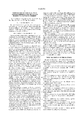
- FIG. 3 illustrates a cross-sectional view of a printed circuit substrate 60 of the present invention.
- Substrate 60 typically comprises an organic epoxy core 62 and a plurality of conductive layers 64a, 64b and 64c that are separated by insulation layers 66a, 66b and 66c.
- the outermost layer of substrate 60 may include a permanent photoresit or other insulation layer 78.
- pad-off-via and pad-on-via contacts 68 and 70 are provided within the substrate structure.
- Pad-off-via and pad-on-via contacts typically comprise a thin copper layer that is bonded or joined to a substrate conductive layer. For example, in FIG.
- pad-off-via contact 68 comprises a copper layer 77 that is connected to conductive layer 64b at via 75.
- Pad-on-via contact 70 comprises a copper layer 71 that is connected to conductive layer 64b at via 76.
- layers 71 and 77 may comprise a material other than copper. In fact, layers 71 and 77 may comprise a multilayered metallurgy.
- FIGS. 4A and 4B show a top view of the pad-off-via contact 68 and pad-on-via contact 70 of substrate 60. As illustrated, the surface area of the contacts differ in size. In addition, as shown in FIG. 3, the depth of contacts relative to the top surface of the substrate also differ. Solder bumps 72 and 74 are formed over the pad-off-via and pad-on-via contacts 68 and 70, respectively. It is important to note that the height 82 and volume of solder bumps 72 and 74 are substantially the same as measured above a horizontal plane 80 that is co-planar to pad-off-via contact 68.
- a reliable solder connection between the solder bumps of substrate 60 and the ball grid array of a flip-chip, or other electronic device may be established.
- substrate 60 is shown having three conductive and three insulation layers, it is understood that the present invention is not limited by the number of conductive and insulation layers. Further, it is appreciated that the pad-off-via and pad-on-via contacts may be connected to any one of the substrate conductive layers.
- the diameter of contact 68 and 70 is approximately 140 and 100 microns, respectively.
- the depth of pad-off-via contact 68, as measured from the top of surface layer 78 to the top of copper layer 77, is approximately 10-30 microns.
- the depth of pad-on-via contact 70, as measured from the top of layer 78 to the top of copper layer 71, is approximately 50-70 microns.
- the thickness of copper layers 71 and 77 is approximately 15 microns.
- C4 soldering which involves aligning the bumps of the flip-chip with corresponding solder bumps on the substrate.
- C4 soldering In order to establish a reliable electrical connection between the flip-chip and substrate, it is important that solder be deposited onto the pad-off and pad-on-via contacts such that the height of the substrate solder bumps are relatively constant along the surface of the substrate. Moreover, it is important to deposit solder onto the substrate contacts such that the volume of solder, as measured above a plane that is co-planar to the pad-off-via contact, is relatively constant.
- solder is deposited onto pad-off and pad-on via contacts 68 and 70 by first positioning a solder mask apparatus 90 over substrate 60 such that mask openings 94 and 96 are aligned with the substrate contact locations.
- openings 94 and 96 are circular in shape and have diameters of approximately 170 and 180 microns, respectively.
- the thickness of mask 90 is approximately 100 microns.
- solder 100 and 102 may comprise any solder material whose properties are conducive to the process just described.
- the solder may comprise a 97/3 Pb/Sn or 95/5 Pb/Sn composition.
- Solder bumps 72 and 74 are formed by reflowing solder 100 and 102 at a temperature of approximately 350 degrees Celsius. The height of solder bumps 72 and 74 is approximately 60 microns as measured from horizontal plane 80 after reflow.
- FIG. 7 illustrates a flow chart of the solder deposition process for making a printed circuit substrate according to the invention.
- An electronic device 110 such as a flip-chip, may be attached to substrate 60 by aligning the ball grid array bumps 112 of device 110 with the solder bumps of substrate 60, as depicted in FIG. 8, and running the unit through a reflow furnace.
- the reflow furnace temperature is set at approximately 350 degrees Celsius.
- FIG. 9 illustrates a flow chart of the connection process for forming a printed circuit substrate according to the invention.
Abstract
A printed circuit substrate having solder bumps formed on pad-on-via contacts and pad-off-via contacts. The printed circuit substrate has at least one pad-on-via contact and at least one pad-off-via contact. A first solder bump is on the pad-on-via contact and a second solder bump is on the pad-off-via contact. The first and second solder bumps are substantially the same height as measured above a horizontal plane that is substantially co-planar to the pad-off-via contact.
Description
This is a divisional of application Ser. No. 08/623,676, filed Mar. 29, 1996 now U.S. Pat. No. 5,660,321.
The present invention is generally directed to printed circuit board processes and products. More particularly, the invention relates to the formation of solder deposits in controlled heights and volume on printed circuit boards containing pad-on and pad-off vias.
Various methods for electrically connecting packaged and unpackaged integrated circuits to printed circuit substrates are well known in the art. On such method uses flip-chips. A flip-chip is an unpackaged integrated circuit device whose bonding pads bear solder bumps which are substantially hemispherical-shaped. The solder bumps typically are made of a tin-lead composition.
Generally, one or more flip-chips are electrically connected to a printed circuit substrate along with other electrical devices to form an electrical circuit. One or both sides of a printed circuit substrate can be used as an active side, which has an interconnection pattern of electrically conductive material (e.g. copper) in which to interconnect the various devices used in the circuit. For the purposes of flip-chip attachment, the substrates interconnection pattern has a number of contact pads defined thereon which correspond to the location and orientation of the solder bumps on a particular flip-chip which may be attached to the printed circuit substrate. One method of connection is controlled collapse chip connection (C4) soldering which involves aligning the bumps of the flip-chip with corresponding wettable solder contacts of the substrate, and then heating the solder to induce reflow and electrical connection between the chip and substrate.
FIG. 1 shows a cross-sectional view of a typical prior art flexible printed circuit substrate 10. Substrate 10 comprises an organic epoxy core 12 and a plurality of conductive layers 14 separated by insulation layers 16. The substrate has a plurality of contact pads 18 for electrically coupling the substrate to other electronic devices, such as flip-chips. Tin-lead solder bumps 20 are generally formed on contact pads 18 to facilitate the attachment of an electrical device, such as a flip-chip, to the printed circuit board. The outermost layer of substrate 10 typically includes a permanent photoresist layer 24.
The contact pads 18, as depicted in FIG. 1, are generally known as pad-on-off via contacts since the contacts do not themselves reside in the substrate vias 22. As shown in FIG. 1, the contacts pads comprise a conductive layer 26 that connects the contacts to the substrate vias 22. Until recently, only pad-off-via have been used on flexible, epoxy printed circuit boards, mainly because of manufacturing limitations. However, the number of I/O's (inputs/outputs) on flip-chip devices has risen to a point where the exclusive use of pad-off-via contacts is impractical in some instances. The need to maximize usable substrate real estate has led to advanced manufacturing techniques that now permit the manufacture of printed circuit substrates containing both pad-off-via and pad-on-via contacts.
It is appreciated that the deposition and reflow of solder on a printed circuit substrate must be precisely controlled to control the height of the solder bumps after soldering. As is well known in the art, controlling the height of solder bumps after reflow is necessary in order to prevent the surface tension of the molten solder bumps from drawing the flip-chip excessively close to the substrate during the reflow process. Moreover, it is appreciated that controlling the height and volume of solder bumps is necessary to produce reliable electrical interconnections.
FIG. 2 illustrates a printed circuit substrate 40 containing both a pad-on-via and a pad-off-via contact 42 and 44, respectively. Since the depths of the pad-off-via and pad-on-via contacts differ, those problems associated with controlling the height and volume of the printed circuit substrate solder bumps are accentuated.
What is needed then is a low cost method for forming reliable connections between surface mounted electronic components and substrates containing both pad-off and pad-on via contacts. As will be seen, the present invention provides a method for controlling the height and volume of solder bumps on printed circuit boards containing pad-off and pad-on via contacts.
The invention provides a printed circuit substrate comprising a plurality of contact pads and solder on the contact pads. The contact pads comprise at least one pad-on-via and at least one pad-off-via. The solder has a first volume on the pad-on-via and a second volume on the pad-off-via. The volumes have surfaces, facing away from the respective vias, which are at least partially co-planar and at least partially electrically unattached.
The present invention is illustrated by way of example and is not limited by the figures of the accompanying drawings, in which like references indicate similar elements, and in which:
FIG. 1 illustrates a cross-sectional view of a typical prior art printed circuit substrate containing only pad-off-via contacts.
FIG. 2 illustrates a cross-sectional view of a printed circuit substrate having both pad-on-via and pad-off-via contacts.
FIG. 3 illustrates a cross-sectional view of a printed circuit substrate of the present invention having solder bumps of a constant height and volume above the pad-off-via contact plane.
FIG. 4A illustrates a top view of a pad adjacent to a via to illustrate a pad-off-via contact.
FIG. 4B illustrates a top view of a pad residing in a via to illustrate a pad-on-via contact.
FIG. 5 illustrates the substrate and solder mask apparatus configuration of one embodiment of the present invention before solder paste is applied over the electrical contact pads of the substrate.
FIG. 6 represents the substrate illustrated in FIG. 5 after solder paste is applied to the pad-on-via and pad-off-via contacts.
FIG. 7 illustrates one flow chart for making a printed circuit substrate according to the invention.
FIG. 8 illustrates another embodiment of the present invention wherein an electronic device is attached to a printed circuit substrate having both pad-on and pad-off via contacts.
FIG. 9 illustrates another flow chart for making a printed circuit substrate according to the invention.
A method for depositing solder onto the pad-on and pad-off via contacts of a substrate is described. In the following description, numerous specific details are set forth such as material types, dimensions, processing steps, etc., in order to provide a thorough understanding of the present invention. However, it will be apparent to one of skill in the art that the invention may be practiced without these specific details. In other instances, well known elements and processing techniques have not been shown in particular detail in order to avoid unnecessarily obscuring the present invention.
FIG. 3 illustrates a cross-sectional view of a printed circuit substrate 60 of the present invention. Substrate 60 typically comprises an organic epoxy core 62 and a plurality of conductive layers 64a, 64b and 64c that are separated by insulation layers 66a, 66b and 66c. The outermost layer of substrate 60 may include a permanent photoresit or other insulation layer 78. To electrically couple selective conductive layers of substrate 60 to other electrical devices, pad-off-via and pad-on-via contacts 68 and 70 are provided within the substrate structure. Pad-off-via and pad-on-via contacts typically comprise a thin copper layer that is bonded or joined to a substrate conductive layer. For example, in FIG. 3, pad-off-via contact 68 comprises a copper layer 77 that is connected to conductive layer 64b at via 75. Pad-on-via contact 70 comprises a copper layer 71 that is connected to conductive layer 64b at via 76. Note that layers 71 and 77 may comprise a material other than copper. In fact, layers 71 and 77 may comprise a multilayered metallurgy.
FIGS. 4A and 4B show a top view of the pad-off-via contact 68 and pad-on-via contact 70 of substrate 60. As illustrated, the surface area of the contacts differ in size. In addition, as shown in FIG. 3, the depth of contacts relative to the top surface of the substrate also differ. Solder bumps 72 and 74 are formed over the pad-off-via and pad-on-via contacts 68 and 70, respectively. It is important to note that the height 82 and volume of solder bumps 72 and 74 are substantially the same as measured above a horizontal plane 80 that is co-planar to pad-off-via contact 68. Therefore, in accordance with the present invention, a reliable solder connection between the solder bumps of substrate 60 and the ball grid array of a flip-chip, or other electronic device, may be established. Although substrate 60 is shown having three conductive and three insulation layers, it is understood that the present invention is not limited by the number of conductive and insulation layers. Further, it is appreciated that the pad-off-via and pad-on-via contacts may be connected to any one of the substrate conductive layers.
In one embodiment, the diameter of contact 68 and 70 is approximately 140 and 100 microns, respectively. The depth of pad-off-via contact 68, as measured from the top of surface layer 78 to the top of copper layer 77, is approximately 10-30 microns. The depth of pad-on-via contact 70, as measured from the top of layer 78 to the top of copper layer 71, is approximately 50-70 microns. The thickness of copper layers 71 and 77 is approximately 15 microns.
As previously discussed, flip-chip and other electronic devices are routinely surface mounted to printed circuit substrates. One method of attachment is controlled collapse chip connection (C4) soldering which involves aligning the bumps of the flip-chip with corresponding solder bumps on the substrate. In order to establish a reliable electrical connection between the flip-chip and substrate, it is important that solder be deposited onto the pad-off and pad-on-via contacts such that the height of the substrate solder bumps are relatively constant along the surface of the substrate. Moreover, it is important to deposit solder onto the substrate contacts such that the volume of solder, as measured above a plane that is co-planar to the pad-off-via contact, is relatively constant.
As depicted in FIGS. 5 and 6, solder is deposited onto pad-off and pad-on via contacts 68 and 70 by first positioning a solder mask apparatus 90 over substrate 60 such that mask openings 94 and 96 are aligned with the substrate contact locations. In one embodiment, openings 94 and 96 are circular in shape and have diameters of approximately 170 and 180 microns, respectively. The thickness of mask 90 is approximately 100 microns. When mask apparatus 90 is in place, solder paste is dispensed onto the top surface 92 of apparatus 90 and then concurrently forced through mask openings 94 and 96 onto contacts 68 and 70 by the use of a squeegee or some other device. The amount of solder paste dispensed through openings 94 and 96 is approximately 2.27×10⁻³ mm3 and 2.54×10⁻³ mm3, respectively. FIG. 6 shows a cross-sectional view of substrate 60 after solder 100 and 102 has been applied to contacts 68 and 70. Solder 100 and 102 may comprise any solder material whose properties are conducive to the process just described. For example, the solder may comprise a 97/3 Pb/Sn or 95/5 Pb/Sn composition. Solder bumps 72 and 74, as depicted in FIG. 3, are formed by reflowing solder 100 and 102 at a temperature of approximately 350 degrees Celsius. The height of solder bumps 72 and 74 is approximately 60 microns as measured from horizontal plane 80 after reflow.
FIG. 7 illustrates a flow chart of the solder deposition process for making a printed circuit substrate according to the invention.
An electronic device 110, such as a flip-chip, may be attached to substrate 60 by aligning the ball grid array bumps 112 of device 110 with the solder bumps of substrate 60, as depicted in FIG. 8, and running the unit through a reflow furnace. In an embodiment wherein the solder bumps of device 110 and substrate 60 comprise 97/3 Pb/Sn, the reflow furnace temperature is set at approximately 350 degrees Celsius. FIG. 9 illustrates a flow chart of the connection process for forming a printed circuit substrate according to the invention.
It is appreciated that the methods and apparatus of the present invention may be used in other technologies to form electrical and/or mechanical connections between other types of electrical devices. It is further understood that the relative dimensions, geometric shapes, materials and process parameters set forth within the specification are exemplary of the disclosed embodiments only. Other embodiments may utilize different dimensions, shapes, materials, and process settings, etc., to achieve substantially the same results.
Claims (4)
1. A printed circuit substrate, comprising:
a multilayer substrate;
at least one pad-on-via contact on the multilayer substrate;
at least one pad-off-via contact on the multilayer substrate, wherein said pad-on-via contact is at a lower height from the bottom of the substrate than said pad-off-via contact;
a first solder bump formed on said pad-on-via contact, said first solder bump having a first exposed surface on a side thereof opposing said pad-on-via contact; and
a second solder bump formed on said pad-off-via contact, said second solder bump having a second exposed surface on a side thereof opposing said pad-off-via contact, the first and second exposed surfaces being at substantially the same height from the bottom of the substrate so as to be capable of establishing a solder connection with an electronic device having contacts at the same height.
2. The printed circuit substrate of claim 1 wherein said solder comprises 97/3 Pb/Sn.
3. The printed circuit substrate of claim 1 wherein said pad-on-via contact has a depth of approximately 50-70 microns.
4. The printed circuit substrate of claim 1 wherein said pad-off-via contact has a depth of approximately 10-30 microns.
Priority Applications (1)
| Application Number | Priority Date | Filing Date | Title |
|---|---|---|---|
| US08/745,470 US6020561A (en) | 1996-03-29 | 1996-11-12 | Printed circuit substrate with solder formed on pad-on-via and pad-off-via contacts thereof |
Applications Claiming Priority (2)
| Application Number | Priority Date | Filing Date | Title |
|---|---|---|---|
| US08/623,676 US5660321A (en) | 1996-03-29 | 1996-03-29 | Method for controlling solder bump height and volume for substrates containing both pad-on and pad-off via contacts |
| US08/745,470 US6020561A (en) | 1996-03-29 | 1996-11-12 | Printed circuit substrate with solder formed on pad-on-via and pad-off-via contacts thereof |
Related Parent Applications (1)
| Application Number | Title | Priority Date | Filing Date |
|---|---|---|---|
| US08/623,676 Division US5660321A (en) | 1996-03-29 | 1996-03-29 | Method for controlling solder bump height and volume for substrates containing both pad-on and pad-off via contacts |
Publications (1)
| Publication Number | Publication Date |
|---|---|
| US6020561A true US6020561A (en) | 2000-02-01 |
Family
ID=24498984
Family Applications (2)
| Application Number | Title | Priority Date | Filing Date |
|---|---|---|---|
| US08/623,676 Expired - Lifetime US5660321A (en) | 1996-03-29 | 1996-03-29 | Method for controlling solder bump height and volume for substrates containing both pad-on and pad-off via contacts |
| US08/745,470 Expired - Lifetime US6020561A (en) | 1996-03-29 | 1996-11-12 | Printed circuit substrate with solder formed on pad-on-via and pad-off-via contacts thereof |
Family Applications Before (1)
| Application Number | Title | Priority Date | Filing Date |
|---|---|---|---|
| US08/623,676 Expired - Lifetime US5660321A (en) | 1996-03-29 | 1996-03-29 | Method for controlling solder bump height and volume for substrates containing both pad-on and pad-off via contacts |
Country Status (3)
| Country | Link |
|---|---|
| US (2) | US5660321A (en) |
| AU (1) | AU2324297A (en) |
| WO (1) | WO1997037520A1 (en) |
Cited By (62)
| Publication number | Priority date | Publication date | Assignee | Title |
|---|---|---|---|---|
| US6085968A (en) * | 1999-01-22 | 2000-07-11 | Hewlett-Packard Company | Solder retention ring for improved solder bump formation |
| US6188138B1 (en) * | 1996-12-19 | 2001-02-13 | Telefonaktiebolaget Lm Ericsson (Pub) | Bumps in grooves for elastic positioning |
| US6194667B1 (en) * | 1998-08-19 | 2001-02-27 | International Business Machines Corporation | Receptor pad structure for chip carriers |
| US6316830B1 (en) | 1998-12-17 | 2001-11-13 | Charles Wen Chyang Lin | Bumpless flip chip assembly with strips and via-fill |
| US6319751B1 (en) * | 1998-12-17 | 2001-11-20 | Charles Wen Chyang Lin | Bumpless flip chip assembly with solder via |
| US6326555B1 (en) * | 1999-02-26 | 2001-12-04 | Fujitsu Limited | Method and structure of z-connected laminated substrate for high density electronic packaging |
| US6350633B1 (en) | 2000-08-22 | 2002-02-26 | Charles W. C. Lin | Semiconductor chip assembly with simultaneously electroplated contact terminal and connection joint |
| US6350632B1 (en) | 2000-09-20 | 2002-02-26 | Charles W. C. Lin | Semiconductor chip assembly with ball bond connection joint |
| US6350386B1 (en) | 2000-09-20 | 2002-02-26 | Charles W. C. Lin | Method of making a support circuit with a tapered through-hole for a semiconductor chip assembly |
| US6396157B2 (en) * | 2000-02-28 | 2002-05-28 | Sharp Kabushiki Kaisha | Semiconductor integrated circuit device and manufacturing method thereof |
| US6403400B2 (en) | 1998-12-17 | 2002-06-11 | Charles Wen Chyang Lin | Bumpless flip chip assembly with strips-in-via and plating |
| US6403460B1 (en) | 2000-08-22 | 2002-06-11 | Charles W. C. Lin | Method of making a semiconductor chip assembly |
| US6402970B1 (en) | 2000-08-22 | 2002-06-11 | Charles W. C. Lin | Method of making a support circuit for a semiconductor chip assembly |
| US6406939B1 (en) | 1998-05-02 | 2002-06-18 | Charles W. C. Lin | Flip chip assembly with via interconnection |
| US6436734B1 (en) | 2000-08-22 | 2002-08-20 | Charles W. C. Lin | Method of making a support circuit for a semiconductor chip assembly |
| US6440835B1 (en) | 2000-10-13 | 2002-08-27 | Charles W. C. Lin | Method of connecting a conductive trace to a semiconductor chip |
| US6444563B1 (en) * | 1999-02-22 | 2002-09-03 | Motorlla, Inc. | Method and apparatus for extending fatigue life of solder joints in a semiconductor device |
| US6444489B1 (en) | 2000-12-15 | 2002-09-03 | Charles W. C. Lin | Semiconductor chip assembly with bumped molded substrate |
| US6448644B1 (en) | 1998-05-02 | 2002-09-10 | Charles W. C. Lin | Flip chip assembly with via interconnection |
| US6448108B1 (en) | 2000-10-02 | 2002-09-10 | Charles W. C. Lin | Method of making a semiconductor chip assembly with a conductive trace subtractively formed before and after chip attachment |
| US6492252B1 (en) | 2000-10-13 | 2002-12-10 | Bridge Semiconductor Corporation | Method of connecting a bumped conductive trace to a semiconductor chip |
| US20020189849A1 (en) * | 1998-05-19 | 2002-12-19 | Ibiden Co., Ltd. | Printed wiring board and manufacturing method of printed wiring board |
| US6511865B1 (en) | 2000-09-20 | 2003-01-28 | Charles W. C. Lin | Method for forming a ball bond connection joint on a conductive trace and conductive pad in a semiconductor chip assembly |
| US6537851B1 (en) | 2000-10-13 | 2003-03-25 | Bridge Semiconductor Corporation | Method of connecting a bumped compliant conductive trace to a semiconductor chip |
| US6544813B1 (en) | 2000-10-02 | 2003-04-08 | Charles W. C. Lin | Method of making a semiconductor chip assembly with a conductive trace subtractively formed before and after chip attachment |
| US6548393B1 (en) | 2000-10-13 | 2003-04-15 | Charles W. C. Lin | Semiconductor chip assembly with hardened connection joint |
| US6551861B1 (en) | 2000-08-22 | 2003-04-22 | Charles W. C. Lin | Method of making a semiconductor chip assembly by joining the chip to a support circuit with an adhesive |
| US6562709B1 (en) | 2000-08-22 | 2003-05-13 | Charles W. C. Lin | Semiconductor chip assembly with simultaneously electroplated contact terminal and connection joint |
| US6562657B1 (en) | 2000-08-22 | 2003-05-13 | Charles W. C. Lin | Semiconductor chip assembly with simultaneously electrolessly plated contact terminal and connection joint |
| US6576539B1 (en) | 2000-10-13 | 2003-06-10 | Charles W.C. Lin | Semiconductor chip assembly with interlocked conductive trace |
| US6576493B1 (en) | 2000-10-13 | 2003-06-10 | Bridge Semiconductor Corporation | Method of connecting a conductive trace and an insulative base to a semiconductor chip using multiple etch steps |
| US6583040B1 (en) | 2000-10-13 | 2003-06-24 | Bridge Semiconductor Corporation | Method of making a pillar in a laminated structure for a semiconductor chip assembly |
| US20030136814A1 (en) * | 2002-01-18 | 2003-07-24 | International Business Machines Corporation | High density raised stud microjoining system and methods of fabricating the same |
| US6630631B1 (en) | 2002-03-27 | 2003-10-07 | Intel Corporation | Apparatus and method for interconnection between a component and a printed circuit board |
| US20030197278A1 (en) * | 2002-04-17 | 2003-10-23 | Rajeev Joshi | Structure of integrated trace of chip package |
| US6653170B1 (en) | 2001-02-06 | 2003-11-25 | Charles W. C. Lin | Semiconductor chip assembly with elongated wire ball bonded to chip and electrolessly plated to support circuit |
| US6660626B1 (en) | 2000-08-22 | 2003-12-09 | Charles W. C. Lin | Semiconductor chip assembly with simultaneously electrolessly plated contact terminal and connection joint |
| US6664482B1 (en) * | 2000-05-01 | 2003-12-16 | Hewlett-Packard Development Company, L.P. | Printed circuit board having solder bridges for electronically connecting conducting pads and method of fabricating solder bridges |
| US6667229B1 (en) | 2000-10-13 | 2003-12-23 | Bridge Semiconductor Corporation | Method of connecting a bumped compliant conductive trace and an insulative base to a semiconductor chip |
| US6670556B1 (en) * | 1999-09-01 | 2003-12-30 | Fujitsu Limited | Printed circuit board unit with detachment mechanism for electronic component |
| US6699780B1 (en) | 2000-10-13 | 2004-03-02 | Bridge Semiconductor Corporation | Method of connecting a conductive trace to a semiconductor chip using plasma undercut etching |
| US6740576B1 (en) | 2000-10-13 | 2004-05-25 | Bridge Semiconductor Corporation | Method of making a contact terminal with a plated metal peripheral sidewall portion for a semiconductor chip assembly |
| US20040141298A1 (en) * | 2003-01-16 | 2004-07-22 | International Business Machines Corporation | Ball grid array package construction with raised solder ball pads |
| US6803528B1 (en) * | 1999-11-05 | 2004-10-12 | 3M Innovative Properties Company | Multi-layer double-sided wiring board and method of fabricating the same |
| US20040222510A1 (en) * | 2003-03-24 | 2004-11-11 | Akiyoshi Aoyagi | Semiconductor device, semiconductor pack age, electronic device, electronic apparatus, and manufacturing methods of semiconductor device and electronic device |
| US20050044702A1 (en) * | 2003-09-03 | 2005-03-03 | Shaeffer Ian P. | Printed circuit board having solder bridges for electronically connecting conducting pads and method of fabricating solder bridges |
| US20050074955A1 (en) * | 2003-10-03 | 2005-04-07 | Vahid Goudarzi | Method and arrangement for reduced thermal stress between substrates |
| US20050253261A1 (en) * | 2003-02-20 | 2005-11-17 | Farnworth Warren M | Electronic device package structures |
| US20060012024A1 (en) * | 2000-10-13 | 2006-01-19 | Bridge Semiconductor Corporation | Semiconductor chip assembly with metal containment wall and solder terminal |
| US20060012048A1 (en) * | 2004-07-07 | 2006-01-19 | Nec Corporation And Nec Electronics Corporation | Wiring substrate for mounting semiconductors, method of manufacturing the same, and semiconductor package |
| US7088002B2 (en) | 2000-12-18 | 2006-08-08 | Intel Corporation | Interconnect |
| US20060180639A1 (en) * | 2005-02-16 | 2006-08-17 | Motorola, Inc. | Method and arrangement for thermally relieved packages with different substrates |
| US20070108623A1 (en) * | 2005-11-11 | 2007-05-17 | Jui-Meng Jao | Chip and package structure |
| US20070200254A1 (en) * | 2006-02-27 | 2007-08-30 | Curry Kenneth M | Method and apparatus for using flex circuit technology to create an electrode |
| US20080135279A1 (en) * | 2006-12-11 | 2008-06-12 | Nec Electronics Corporation | Printed wiring board having plural solder resist layers and method for production thereof |
| US7750483B1 (en) | 2004-11-10 | 2010-07-06 | Bridge Semiconductor Corporation | Semiconductor chip assembly with welded metal pillar and enlarged plated contact terminal |
| US7811863B1 (en) | 2006-10-26 | 2010-10-12 | Bridge Semiconductor Corporation | Method of making a semiconductor chip assembly with metal pillar and encapsulant grinding and heat sink attachment |
| US7833827B1 (en) | 2003-11-20 | 2010-11-16 | Bridge Semiconductor Corporation | Method of making a semiconductor chip assembly with a bumped terminal, a filler and an insulative base |
| US7932165B1 (en) | 2003-11-20 | 2011-04-26 | Bridge Semiconductor Corporation | Method of making a semiconductor chip assembly with a laterally aligned filler and insulative base |
| US7993983B1 (en) | 2003-11-17 | 2011-08-09 | Bridge Semiconductor Corporation | Method of making a semiconductor chip assembly with chip and encapsulant grinding |
| US20150041208A1 (en) * | 2013-08-07 | 2015-02-12 | Invensas Corporation | Micro mechanical anchor for 3d architecture |
| US20190115312A1 (en) * | 2013-11-18 | 2019-04-18 | Taiwan Semiconductor Manufacturing Company Ltd. | Semiconductor device and fabricating method thereof |
Families Citing this family (20)
| Publication number | Priority date | Publication date | Assignee | Title |
|---|---|---|---|---|
| EP0841840A1 (en) * | 1996-11-12 | 1998-05-13 | Hewlett-Packard Company | Method for the manufacture of micro solder bumps on copper pads |
| US6137688A (en) * | 1996-12-31 | 2000-10-24 | Intel Corporation | Apparatus for retrofit mounting a VLSI chip to a computer chassis for current supply |
| TW362342B (en) * | 1997-10-27 | 1999-06-21 | Sony Video Taiwan Co Ltd | Method for combining e-mail network with pager |
| US5984164A (en) | 1997-10-31 | 1999-11-16 | Micron Technology, Inc. | Method of using an electrically conductive elevation shaping tool |
| US5889655A (en) * | 1997-11-26 | 1999-03-30 | Intel Corporation | Integrated circuit package substrate with stepped solder mask openings |
| US6115262A (en) * | 1998-06-08 | 2000-09-05 | Ford Motor Company | Enhanced mounting pads for printed circuit boards |
| US6145735A (en) * | 1998-09-10 | 2000-11-14 | Lockheed Martin Corporation | Thin film solder paste deposition method and tools |
| JP3399518B2 (en) * | 1999-03-03 | 2003-04-21 | インターナショナル・ビジネス・マシーンズ・コーポレーション | Semiconductor structure and method of manufacturing the same |
| US6427901B2 (en) * | 1999-06-30 | 2002-08-06 | Lucent Technologies Inc. | System and method for forming stable solder bonds |
| JP3459380B2 (en) | 1999-06-30 | 2003-10-20 | 日本特殊陶業株式会社 | Manufacturing method of printed wiring board and mask |
| US7331500B2 (en) * | 2004-06-25 | 2008-02-19 | Intel Corporation | Solder bumps formation using solder paste with shape retaining attribute |
| CN101283631B (en) * | 2005-12-20 | 2010-06-09 | 揖斐电株式会社 | Method for manufacturing printed wiring board |
| TW200742515A (en) * | 2006-01-27 | 2007-11-01 | Ibiden Co Ltd | Printed-circuit board, and method for manufacturing the same |
| US20070228091A1 (en) * | 2006-03-30 | 2007-10-04 | Jack Shawen | Back support with straps that is changeable with storage area |
| US20080029686A1 (en) * | 2006-08-04 | 2008-02-07 | International Business Machines Corporation | Precision fabricated silicon mold |
| US7993971B2 (en) * | 2007-12-28 | 2011-08-09 | Freescale Semiconductor, Inc. | Forming a 3-D semiconductor die structure with an intermetallic formation |
| US8420950B2 (en) * | 2010-03-02 | 2013-04-16 | Stats Chippac Ltd. | Circuit system with leads and method of manufacture thereof |
| WO2020000414A1 (en) * | 2018-06-29 | 2020-01-02 | Intel Corporation | Coupling mechanisms for substrates, semiconductor packages, and/or printed circuit boards |
| WO2022000173A1 (en) * | 2020-06-29 | 2022-01-06 | 庆鼎精密电子(淮安)有限公司 | Circuit board and manufacturing method therefor |
| TWI802973B (en) * | 2021-08-24 | 2023-05-21 | 矽品精密工業股份有限公司 | Substrate structure |
Citations (12)
| Publication number | Priority date | Publication date | Assignee | Title |
|---|---|---|---|---|
| US3458925A (en) * | 1966-01-20 | 1969-08-05 | Ibm | Method of forming solder mounds on substrates |
| EP0263944A1 (en) * | 1986-09-15 | 1988-04-20 | International Business Machines Corporation | A method of squeegeeing solder paste onto and into a printed circuit board |
| US4764804A (en) * | 1986-02-21 | 1988-08-16 | Hitachi, Ltd. | Semiconductor device and process for producing the same |
| EP0499079A1 (en) * | 1991-02-11 | 1992-08-19 | International Business Machines Corporation | Electronic packaging with varying height connectors |
| US5214308A (en) * | 1990-01-23 | 1993-05-25 | Sumitomo Electric Industries, Ltd. | Substrate for packaging a semiconductor device |
| US5255839A (en) * | 1992-01-02 | 1993-10-26 | Motorola, Inc. | Method for solder application and reflow |
| US5261593A (en) * | 1992-08-19 | 1993-11-16 | Sheldahl, Inc. | Direct application of unpackaged integrated circuit to flexible printed circuit |
| US5400950A (en) * | 1994-02-22 | 1995-03-28 | Delco Electronics Corporation | Method for controlling solder bump height for flip chip integrated circuit devices |
| US5489750A (en) * | 1993-03-11 | 1996-02-06 | Matsushita Electric Industrial Co., Ltd. | Method of mounting an electronic part with bumps on a circuit board |
| US5493075A (en) * | 1994-09-30 | 1996-02-20 | International Business Machines Corporation | Fine pitch solder formation on printed circuit board process and product |
| US5521435A (en) * | 1993-12-13 | 1996-05-28 | Fujitsu Limited | Semiconductor device and a fabrication process thereof |
| US5591941A (en) * | 1993-10-28 | 1997-01-07 | International Business Machines Corporation | Solder ball interconnected assembly |
Family Cites Families (4)
| Publication number | Priority date | Publication date | Assignee | Title |
|---|---|---|---|---|
| US4704305A (en) * | 1984-03-06 | 1987-11-03 | Northern Telecom Limited | Automatic solder paste application to circuit boards |
| JPS63202989A (en) * | 1987-02-19 | 1988-08-22 | 株式会社日立製作所 | Soldering |
| JPH05200542A (en) * | 1992-01-21 | 1993-08-10 | Sony Corp | Method for applying cream solder |
| JPH06177526A (en) * | 1992-12-09 | 1994-06-24 | Toyota Autom Loom Works Ltd | Printing method for bonding agent |
-
1996
- 1996-03-29 US US08/623,676 patent/US5660321A/en not_active Expired - Lifetime
- 1996-11-12 US US08/745,470 patent/US6020561A/en not_active Expired - Lifetime
-
1997
- 1997-03-13 AU AU23242/97A patent/AU2324297A/en not_active Abandoned
- 1997-03-13 WO PCT/US1997/003997 patent/WO1997037520A1/en active Application Filing
Patent Citations (12)
| Publication number | Priority date | Publication date | Assignee | Title |
|---|---|---|---|---|
| US3458925A (en) * | 1966-01-20 | 1969-08-05 | Ibm | Method of forming solder mounds on substrates |
| US4764804A (en) * | 1986-02-21 | 1988-08-16 | Hitachi, Ltd. | Semiconductor device and process for producing the same |
| EP0263944A1 (en) * | 1986-09-15 | 1988-04-20 | International Business Machines Corporation | A method of squeegeeing solder paste onto and into a printed circuit board |
| US5214308A (en) * | 1990-01-23 | 1993-05-25 | Sumitomo Electric Industries, Ltd. | Substrate for packaging a semiconductor device |
| EP0499079A1 (en) * | 1991-02-11 | 1992-08-19 | International Business Machines Corporation | Electronic packaging with varying height connectors |
| US5255839A (en) * | 1992-01-02 | 1993-10-26 | Motorola, Inc. | Method for solder application and reflow |
| US5261593A (en) * | 1992-08-19 | 1993-11-16 | Sheldahl, Inc. | Direct application of unpackaged integrated circuit to flexible printed circuit |
| US5489750A (en) * | 1993-03-11 | 1996-02-06 | Matsushita Electric Industrial Co., Ltd. | Method of mounting an electronic part with bumps on a circuit board |
| US5591941A (en) * | 1993-10-28 | 1997-01-07 | International Business Machines Corporation | Solder ball interconnected assembly |
| US5521435A (en) * | 1993-12-13 | 1996-05-28 | Fujitsu Limited | Semiconductor device and a fabrication process thereof |
| US5400950A (en) * | 1994-02-22 | 1995-03-28 | Delco Electronics Corporation | Method for controlling solder bump height for flip chip integrated circuit devices |
| US5493075A (en) * | 1994-09-30 | 1996-02-20 | International Business Machines Corporation | Fine pitch solder formation on printed circuit board process and product |
Cited By (105)
| Publication number | Priority date | Publication date | Assignee | Title |
|---|---|---|---|---|
| US6188138B1 (en) * | 1996-12-19 | 2001-02-13 | Telefonaktiebolaget Lm Ericsson (Pub) | Bumps in grooves for elastic positioning |
| US6448644B1 (en) | 1998-05-02 | 2002-09-10 | Charles W. C. Lin | Flip chip assembly with via interconnection |
| US6406939B1 (en) | 1998-05-02 | 2002-06-18 | Charles W. C. Lin | Flip chip assembly with via interconnection |
| US20090159327A1 (en) * | 1998-05-19 | 2009-06-25 | Ibiden Co., Ltd. | Printed wiring board and manufacturing method of printed wiring board |
| US8629550B2 (en) | 1998-05-19 | 2014-01-14 | Ibiden Co., Ltd. | Printed wiring board with crossing wiring pattern |
| US7525190B2 (en) | 1998-05-19 | 2009-04-28 | Ibiden Co., Ltd. | Printed wiring board with wiring pattern having narrow width portion |
| US20050158553A1 (en) * | 1998-05-19 | 2005-07-21 | Ibiden Co., Ltd. | Printed wiring board and manufacturing method of printed wiring board |
| US8018046B2 (en) | 1998-05-19 | 2011-09-13 | Ibiden Co., Ltd. | Printed wiring board with notched conductive traces |
| US7332816B2 (en) * | 1998-05-19 | 2008-02-19 | Ibiden Co., Ltd. | Method of fabricating crossing wiring pattern on a printed circuit board |
| US20020189849A1 (en) * | 1998-05-19 | 2002-12-19 | Ibiden Co., Ltd. | Printed wiring board and manufacturing method of printed wiring board |
| US6194667B1 (en) * | 1998-08-19 | 2001-02-27 | International Business Machines Corporation | Receptor pad structure for chip carriers |
| US6403400B2 (en) | 1998-12-17 | 2002-06-11 | Charles Wen Chyang Lin | Bumpless flip chip assembly with strips-in-via and plating |
| US6475833B2 (en) | 1998-12-17 | 2002-11-05 | Charles Wen Chyang Lin | Bumpless flip chip assembly with strips and via-fill |
| US6437452B2 (en) | 1998-12-17 | 2002-08-20 | Charles Wen Chyang Lin | Bumpless flip chip assembly with strips-in-via and plating |
| US6528891B2 (en) | 1998-12-17 | 2003-03-04 | Charles Wen Chyang Lin | Bumpless flip chip assembly with solder via |
| US6319751B1 (en) * | 1998-12-17 | 2001-11-20 | Charles Wen Chyang Lin | Bumpless flip chip assembly with solder via |
| US6316830B1 (en) | 1998-12-17 | 2001-11-13 | Charles Wen Chyang Lin | Bumpless flip chip assembly with strips and via-fill |
| US6085968A (en) * | 1999-01-22 | 2000-07-11 | Hewlett-Packard Company | Solder retention ring for improved solder bump formation |
| US6444563B1 (en) * | 1999-02-22 | 2002-09-03 | Motorlla, Inc. | Method and apparatus for extending fatigue life of solder joints in a semiconductor device |
| US6326555B1 (en) * | 1999-02-26 | 2001-12-04 | Fujitsu Limited | Method and structure of z-connected laminated substrate for high density electronic packaging |
| US6670556B1 (en) * | 1999-09-01 | 2003-12-30 | Fujitsu Limited | Printed circuit board unit with detachment mechanism for electronic component |
| US20050077079A1 (en) * | 1999-09-01 | 2005-04-14 | Fujitsu Limited | Printed circuit board unit with detachment mechanism for electronic component |
| US6803528B1 (en) * | 1999-11-05 | 2004-10-12 | 3M Innovative Properties Company | Multi-layer double-sided wiring board and method of fabricating the same |
| US6396157B2 (en) * | 2000-02-28 | 2002-05-28 | Sharp Kabushiki Kaisha | Semiconductor integrated circuit device and manufacturing method thereof |
| US6664482B1 (en) * | 2000-05-01 | 2003-12-16 | Hewlett-Packard Development Company, L.P. | Printed circuit board having solder bridges for electronically connecting conducting pads and method of fabricating solder bridges |
| US20040041001A1 (en) * | 2000-05-01 | 2004-03-04 | Shaeffer Ian P. | Printed circuit board having solder bridges for electronically connecting conducting pads and method of fabricating solder bridges |
| US7412923B2 (en) | 2000-05-01 | 2008-08-19 | Hewlett-Packard Development Company, L.P. | Stencil device for accurately applying solder paste to a printed circuit board |
| US6436734B1 (en) | 2000-08-22 | 2002-08-20 | Charles W. C. Lin | Method of making a support circuit for a semiconductor chip assembly |
| US6403460B1 (en) | 2000-08-22 | 2002-06-11 | Charles W. C. Lin | Method of making a semiconductor chip assembly |
| US6551861B1 (en) | 2000-08-22 | 2003-04-22 | Charles W. C. Lin | Method of making a semiconductor chip assembly by joining the chip to a support circuit with an adhesive |
| US6562709B1 (en) | 2000-08-22 | 2003-05-13 | Charles W. C. Lin | Semiconductor chip assembly with simultaneously electroplated contact terminal and connection joint |
| US6562657B1 (en) | 2000-08-22 | 2003-05-13 | Charles W. C. Lin | Semiconductor chip assembly with simultaneously electrolessly plated contact terminal and connection joint |
| US6350633B1 (en) | 2000-08-22 | 2002-02-26 | Charles W. C. Lin | Semiconductor chip assembly with simultaneously electroplated contact terminal and connection joint |
| US6402970B1 (en) | 2000-08-22 | 2002-06-11 | Charles W. C. Lin | Method of making a support circuit for a semiconductor chip assembly |
| US6660626B1 (en) | 2000-08-22 | 2003-12-09 | Charles W. C. Lin | Semiconductor chip assembly with simultaneously electrolessly plated contact terminal and connection joint |
| US6350386B1 (en) | 2000-09-20 | 2002-02-26 | Charles W. C. Lin | Method of making a support circuit with a tapered through-hole for a semiconductor chip assembly |
| US6627824B1 (en) | 2000-09-20 | 2003-09-30 | Charles W. C. Lin | Support circuit with a tapered through-hole for a semiconductor chip assembly |
| US6350632B1 (en) | 2000-09-20 | 2002-02-26 | Charles W. C. Lin | Semiconductor chip assembly with ball bond connection joint |
| US6511865B1 (en) | 2000-09-20 | 2003-01-28 | Charles W. C. Lin | Method for forming a ball bond connection joint on a conductive trace and conductive pad in a semiconductor chip assembly |
| US6544813B1 (en) | 2000-10-02 | 2003-04-08 | Charles W. C. Lin | Method of making a semiconductor chip assembly with a conductive trace subtractively formed before and after chip attachment |
| US6448108B1 (en) | 2000-10-02 | 2002-09-10 | Charles W. C. Lin | Method of making a semiconductor chip assembly with a conductive trace subtractively formed before and after chip attachment |
| US6608374B1 (en) | 2000-10-13 | 2003-08-19 | Bridge Semiconductor Corporation | Semiconductor chip assembly with bumped conductive trace |
| US6800506B1 (en) | 2000-10-13 | 2004-10-05 | Bridge Semiconductor Corporation | Method of making a bumped terminal in a laminated structure for a semiconductor chip assembly |
| US6653217B1 (en) | 2000-10-13 | 2003-11-25 | Charles W. C. Lin | Method of connecting a conductive trace to a semiconductor chip |
| US6653742B1 (en) | 2000-10-13 | 2003-11-25 | Charles W. C. Lin | Semiconductor chip assembly with interlocked conductive trace |
| US6667229B1 (en) | 2000-10-13 | 2003-12-23 | Bridge Semiconductor Corporation | Method of connecting a bumped compliant conductive trace and an insulative base to a semiconductor chip |
| US6576539B1 (en) | 2000-10-13 | 2003-06-10 | Charles W.C. Lin | Semiconductor chip assembly with interlocked conductive trace |
| US6673710B1 (en) | 2000-10-13 | 2004-01-06 | Bridge Semiconductor Corporation | Method of connecting a conductive trace and an insulative base to a semiconductor chip |
| US6699780B1 (en) | 2000-10-13 | 2004-03-02 | Bridge Semiconductor Corporation | Method of connecting a conductive trace to a semiconductor chip using plasma undercut etching |
| US6440835B1 (en) | 2000-10-13 | 2002-08-27 | Charles W. C. Lin | Method of connecting a conductive trace to a semiconductor chip |
| US6537851B1 (en) | 2000-10-13 | 2003-03-25 | Bridge Semiconductor Corporation | Method of connecting a bumped compliant conductive trace to a semiconductor chip |
| US6548393B1 (en) | 2000-10-13 | 2003-04-15 | Charles W. C. Lin | Semiconductor chip assembly with hardened connection joint |
| US6740576B1 (en) | 2000-10-13 | 2004-05-25 | Bridge Semiconductor Corporation | Method of making a contact terminal with a plated metal peripheral sidewall portion for a semiconductor chip assembly |
| US6583040B1 (en) | 2000-10-13 | 2003-06-24 | Bridge Semiconductor Corporation | Method of making a pillar in a laminated structure for a semiconductor chip assembly |
| US6492252B1 (en) | 2000-10-13 | 2002-12-10 | Bridge Semiconductor Corporation | Method of connecting a bumped conductive trace to a semiconductor chip |
| US6576493B1 (en) | 2000-10-13 | 2003-06-10 | Bridge Semiconductor Corporation | Method of connecting a conductive trace and an insulative base to a semiconductor chip using multiple etch steps |
| US6809414B1 (en) | 2000-10-13 | 2004-10-26 | Bridge Semiconductor Corporation | Semiconductor chip assembly with bumped conductive trace |
| US20060014316A1 (en) * | 2000-10-13 | 2006-01-19 | Bridge Semiconductor Corporation | Method of making a semiconductor chip assemby with a metal containment wall and a solder terminal |
| US20060012024A1 (en) * | 2000-10-13 | 2006-01-19 | Bridge Semiconductor Corporation | Semiconductor chip assembly with metal containment wall and solder terminal |
| US6444489B1 (en) | 2000-12-15 | 2002-09-03 | Charles W. C. Lin | Semiconductor chip assembly with bumped molded substrate |
| US7375432B2 (en) | 2000-12-18 | 2008-05-20 | Intel Corporation | Via attached to a bond pad utilizing a tapered interconnect |
| US7638419B2 (en) | 2000-12-18 | 2009-12-29 | Intel Corporation | Method of fabricating a via attached to a bond pad utilizing a tapered interconnect |
| US7088002B2 (en) | 2000-12-18 | 2006-08-08 | Intel Corporation | Interconnect |
| US20080090406A1 (en) * | 2000-12-18 | 2008-04-17 | Intel Corporation | Via attached to a bond pad utilizing a tapered interconnect |
| US20060191712A1 (en) * | 2000-12-18 | 2006-08-31 | Intel Corporation | Interconnect |
| US6653170B1 (en) | 2001-02-06 | 2003-11-25 | Charles W. C. Lin | Semiconductor chip assembly with elongated wire ball bonded to chip and electrolessly plated to support circuit |
| US20030136814A1 (en) * | 2002-01-18 | 2003-07-24 | International Business Machines Corporation | High density raised stud microjoining system and methods of fabricating the same |
| US6732908B2 (en) * | 2002-01-18 | 2004-05-11 | International Business Machines Corporation | High density raised stud microjoining system and methods of fabricating the same |
| US20040084210A1 (en) * | 2002-03-27 | 2004-05-06 | Dishongh Terrance J. | Apparatus and method for interconnection between a component and a printed circuit board |
| US6630631B1 (en) | 2002-03-27 | 2003-10-07 | Intel Corporation | Apparatus and method for interconnection between a component and a printed circuit board |
| US6836023B2 (en) * | 2002-04-17 | 2004-12-28 | Fairchild Semiconductor Corporation | Structure of integrated trace of chip package |
| US20030197278A1 (en) * | 2002-04-17 | 2003-10-23 | Rajeev Joshi | Structure of integrated trace of chip package |
| US20040141298A1 (en) * | 2003-01-16 | 2004-07-22 | International Business Machines Corporation | Ball grid array package construction with raised solder ball pads |
| US7253510B2 (en) * | 2003-01-16 | 2007-08-07 | International Business Machines Corporation | Ball grid array package construction with raised solder ball pads |
| US8153516B2 (en) | 2003-01-16 | 2012-04-10 | International Business Machines Corporation | Method of ball grid array package construction with raised solder ball pads |
| US7816754B2 (en) | 2003-01-16 | 2010-10-19 | International Business Machines Corporation | Ball grid array package construction with raised solder ball pads |
| US8129839B2 (en) * | 2003-02-20 | 2012-03-06 | Micron Technology, Inc. | Electronic device package structures |
| US20050253261A1 (en) * | 2003-02-20 | 2005-11-17 | Farnworth Warren M | Electronic device package structures |
| US7091619B2 (en) * | 2003-03-24 | 2006-08-15 | Seiko Epson Corporation | Semiconductor device, semiconductor package, electronic device, electronic apparatus, and manufacturing methods of semiconductor device and electronic device |
| US20040222510A1 (en) * | 2003-03-24 | 2004-11-11 | Akiyoshi Aoyagi | Semiconductor device, semiconductor pack age, electronic device, electronic apparatus, and manufacturing methods of semiconductor device and electronic device |
| US20050044702A1 (en) * | 2003-09-03 | 2005-03-03 | Shaeffer Ian P. | Printed circuit board having solder bridges for electronically connecting conducting pads and method of fabricating solder bridges |
| US7140531B2 (en) | 2003-09-03 | 2006-11-28 | Hewlett-Packard Development Company, L.P. | Method of fabricating a substantially zero signal degradation electrical connection on a printed circuit broad |
| US8390126B2 (en) * | 2003-10-03 | 2013-03-05 | Motorola Mobility Llc | Method and arrangement for reduced thermal stress between substrates |
| US20050074955A1 (en) * | 2003-10-03 | 2005-04-07 | Vahid Goudarzi | Method and arrangement for reduced thermal stress between substrates |
| US7993983B1 (en) | 2003-11-17 | 2011-08-09 | Bridge Semiconductor Corporation | Method of making a semiconductor chip assembly with chip and encapsulant grinding |
| US7932165B1 (en) | 2003-11-20 | 2011-04-26 | Bridge Semiconductor Corporation | Method of making a semiconductor chip assembly with a laterally aligned filler and insulative base |
| US7833827B1 (en) | 2003-11-20 | 2010-11-16 | Bridge Semiconductor Corporation | Method of making a semiconductor chip assembly with a bumped terminal, a filler and an insulative base |
| US8198140B2 (en) | 2004-07-07 | 2012-06-12 | Nec Corporation | Wiring substrate for mounting semiconductors, method of manufacturing the same, and semiconductor package |
| US20110003472A1 (en) * | 2004-07-07 | 2011-01-06 | Nec Corporation | Wiring substrate for mounting semiconductors, method of manufacturing the same, and semiconductor package |
| US7816782B2 (en) * | 2004-07-07 | 2010-10-19 | Nec Corporation | Wiring substrate for mounting semiconductors, method of manufacturing the same, and semiconductor package |
| US20060012048A1 (en) * | 2004-07-07 | 2006-01-19 | Nec Corporation And Nec Electronics Corporation | Wiring substrate for mounting semiconductors, method of manufacturing the same, and semiconductor package |
| US7750483B1 (en) | 2004-11-10 | 2010-07-06 | Bridge Semiconductor Corporation | Semiconductor chip assembly with welded metal pillar and enlarged plated contact terminal |
| US7413110B2 (en) | 2005-02-16 | 2008-08-19 | Motorola, Inc. | Method for reducing stress between substrates of differing materials |
| US20060180639A1 (en) * | 2005-02-16 | 2006-08-17 | Motorola, Inc. | Method and arrangement for thermally relieved packages with different substrates |
| US20070108623A1 (en) * | 2005-11-11 | 2007-05-17 | Jui-Meng Jao | Chip and package structure |
| US7518211B2 (en) * | 2005-11-11 | 2009-04-14 | United Microelectronics Corp. | Chip and package structure |
| US8065796B2 (en) * | 2006-02-27 | 2011-11-29 | Edwards Lifesciences Corporation | Method and apparatus for using flex circuit technology to create an electrode |
| US8546701B2 (en) | 2006-02-27 | 2013-10-01 | Edwards Lifesciences Corporation | Method and apparatus for using flex circuit technology to create an electrode |
| US20070200254A1 (en) * | 2006-02-27 | 2007-08-30 | Curry Kenneth M | Method and apparatus for using flex circuit technology to create an electrode |
| US7811863B1 (en) | 2006-10-26 | 2010-10-12 | Bridge Semiconductor Corporation | Method of making a semiconductor chip assembly with metal pillar and encapsulant grinding and heat sink attachment |
| US20080135279A1 (en) * | 2006-12-11 | 2008-06-12 | Nec Electronics Corporation | Printed wiring board having plural solder resist layers and method for production thereof |
| US20150041208A1 (en) * | 2013-08-07 | 2015-02-12 | Invensas Corporation | Micro mechanical anchor for 3d architecture |
| US9832887B2 (en) * | 2013-08-07 | 2017-11-28 | Invensas Corporation | Micro mechanical anchor for 3D architecture |
| US20190115312A1 (en) * | 2013-11-18 | 2019-04-18 | Taiwan Semiconductor Manufacturing Company Ltd. | Semiconductor device and fabricating method thereof |
| US10985121B2 (en) * | 2013-11-18 | 2021-04-20 | Taiwan Semiconductor Manufacturing Company Ltd. | Bump structure and fabricating method thereof |
Also Published As
| Publication number | Publication date |
|---|---|
| AU2324297A (en) | 1997-10-22 |
| WO1997037520A1 (en) | 1997-10-09 |
| US5660321A (en) | 1997-08-26 |
Similar Documents
| Publication | Publication Date | Title |
|---|---|---|
| US6020561A (en) | Printed circuit substrate with solder formed on pad-on-via and pad-off-via contacts thereof | |
| US5133495A (en) | Method of bonding flexible circuit to circuitized substrate to provide electrical connection therebetween | |
| US5261155A (en) | Method for bonding flexible circuit to circuitized substrate to provide electrical connection therebetween using different solders | |
| US6184062B1 (en) | Process for forming cone shaped solder for chip interconnection | |
| US5203075A (en) | Method of bonding flexible circuit to cicuitized substrate to provide electrical connection therebetween using different solders | |
| JP3898891B2 (en) | Via plug adapter | |
| EP0263222B1 (en) | Method of forming solder terminals for a pinless ceramic module | |
| US6245594B1 (en) | Methods for forming conductive micro-bumps and recessed contacts for flip-chip technology and method of flip-chip assembly | |
| US5463191A (en) | Circuit board having an improved fine pitch ball grid array and method of assembly therefor | |
| US6107122A (en) | Direct die contact (DDC) semiconductor package | |
| US8299368B2 (en) | Interconnection element for electric circuits | |
| KR100287393B1 (en) | Substrate structure and method for improving attachment reliability of semiconductor chips and modules | |
| US8558378B2 (en) | Bump-on-lead flip chip interconnection | |
| KR970012964A (en) | A system interconnected by bond material bumps | |
| US6514845B1 (en) | Solder ball contact and method | |
| US20060191134A1 (en) | Patch substrate for external connection | |
| JPH098451A (en) | Method of manufacturing chip mounting circuit card | |
| WO2009009694A2 (en) | Solder cap application process on copper bump using solder powder film | |
| JP3143441B2 (en) | Solder bump input / output pads for surface mount circuit devices | |
| US7545028B2 (en) | Solder ball assembly for a semiconductor device and method of fabricating same | |
| US6528873B1 (en) | Ball grid assembly with solder columns | |
| JPH04233792A (en) | Method of junctioning elect- ronic part with circuit board | |
| US20110061907A1 (en) | Printed circuit board and method of manufacturing the same | |
| JPH11168279A (en) | Multilayer circuit board and manufacture thereof | |
| US7235429B2 (en) | Conductive block mounting process for electrical connection |
Legal Events
| Date | Code | Title | Description |
|---|---|---|---|
| STCF | Information on status: patent grant |
Free format text: PATENTED CASE |
|
| FPAY | Fee payment |
Year of fee payment: 4 |
|
| FPAY | Fee payment |
Year of fee payment: 8 |
|
| FPAY | Fee payment |
Year of fee payment: 12 |