US6002957A - EMG electrode array support belt - Google Patents
EMG electrode array support belt Download PDFInfo
- Publication number
- US6002957A US6002957A US09/059,783 US5978398A US6002957A US 6002957 A US6002957 A US 6002957A US 5978398 A US5978398 A US 5978398A US 6002957 A US6002957 A US 6002957A
- Authority
- US
- United States
- Prior art keywords
- patient
- electrode
- electrodes
- support member
- signals
- Prior art date
- Legal status (The legal status is an assumption and is not a legal conclusion. Google has not performed a legal analysis and makes no representation as to the accuracy of the status listed.)
- Expired - Lifetime
Links
Images


Classifications
-
- A—HUMAN NECESSITIES
- A61—MEDICAL OR VETERINARY SCIENCE; HYGIENE
- A61B—DIAGNOSIS; SURGERY; IDENTIFICATION
- A61B5/00—Measuring for diagnostic purposes; Identification of persons
- A61B5/24—Detecting, measuring or recording bioelectric or biomagnetic signals of the body or parts thereof
- A61B5/25—Bioelectric electrodes therefor
- A61B5/279—Bioelectric electrodes therefor specially adapted for particular uses
- A61B5/296—Bioelectric electrodes therefor specially adapted for particular uses for electromyography [EMG]
Definitions
- This invention relates to a method and apparatus for monitoring and displaying the condition of muscles in a muscle group by the sensing and analysis of electromyographic signals derived from a non-invasive body surface electrode array positioned close to the muscle group.
- Prutchi Typical of this prior art is the device described by D. Prutchi in the publication "A High-Resolution Large Array (HRLA) EMG System", published September 1995 in Med. Eng. Phys., Vol. 17, 442-454. Prutchi describes a bracelet which may be wrapped about a body limb and which contains 256 surface electrodes to record the electrical activity of underlying muscles. The electrodes are arranged in eight groups of thirty-two electrode linear arrays directly connected to buffer boards in close proximity of the electrodes.
- HRLA High-Resolution Large Array
- U.S. Pat. No. 5,086,779 to DeLuca, et al. describes a back analysis system of plural electrodes coupled to a computer system for processing the signals and to provide graphical representations of results.
- DeLuca's invention relates primarily to isolating particular muscle groups by the use of support and restraint devices which limit the movement of the patient's torso in predetermined patterns correlated to the desired muscle groups.
- DeLuca's electrode array consists of separate electrodes individually placed at desired locations on a patient's back.
- U.S. Pat. No. 5,058,602 to Brody describes a method of electromyographic scanning of paravertebral muscles comprising measuring electrical potentials bilaterally across segments of the spine. Readings are categorized into different patterns which are indicative of different muscular conditions. Brody suggests equipment useful within his described techniques as an available EMG scanner having electrodes spaced 2.5 cm apart and a computer component, but provides few details on the equipment or an indication of usefulness for isolating certain muscles or muscle groups.
- Kadefors' electrode system comprises three electrodes, one of which is a reference marker.
- This electronic apparatus in essence, includes a sample and hold function in which current responses can be compared to earlier responses and an indication provided based on the differences detected.
- U.S. Pat. No. 5,505,208 to Toormin, et al. describes a method for determining the status of back muscles wherein EMG signals are monitored from a number of electrodes placed in a pattern on a patient's back, the activity of each electrode is determined and the results stored.
- a database of results provides a standard from which comparisons can be made to determine deviations or abnormalities, as a device for the care and management of the patient's dysfunction.
- U.S. Pat. No. 5,513,651 to Cusimano, et al. describes a portable electronic instrument for monitoring muscle activity, using standard ECG electrodes and a computer for analyzing the detected signals.
- the electrodes are applied individually at predetermined locations and a range of motion device is employed to generate signals related to a particular muscle group.
- Output plots are produced to provide an indication of results, apparently in the form of printouts of information reflecting any deviations from the norm of expected muscle activity.
- An object of the present invention is to provide improved surface EMG equipment, readily useable by the skilled examining physician, for the diagnosis or treatment monitoring of patients with low back pain.
- a further object of the present invention is to provide an improved clinical tool which is portable and which uses non-invasive techniques for the collection of signals.
- a further object of the present invention is to provide improved EMG equipment which provides a visual display of the activity of muscles or muscle groups.
- a further object of the present invention is to provide improved EMG equipment in which the visual display of muscle activity is juxtaposed over a visual display of normal muscle anatomy for correlation by the examining physician.
- a further object of the present invention is to provide improved EMG equipment in which the visual display can be selected for specific musculature identified by the examining physician.
- a further object of the present invention is to provide improved EMG equipment which utilizes a single detector pad of electrodes in which the electrodes are arranged in a specific array, to monitor instantaneously all specific muscles in a muscle group of a patient.
- the electromyographic (EMG) diagnostic system of the present invention is particularly suited for evaluation of the lower back of a human and consists essentially of a sensor pad for collecting and conditioning EMG signals, electronic equipment including a computer for signal discrimination and evaluation and a display device for providing a visual display of the activity of selected musculature.
- a ground electrode is positioned on the patient.
- the electronic equipment serves to receive signals from the sensor pad which is pressed against the lower back of a patient in a predetermined location and held immobile relative to the patient such as by strap with foam backing, an inflatable bladder, an adhesive pad or other convenient arrangement. Signals from individual electrodes are conditioned by the electrical equipment, discriminated from noise signals and the like and evaluated relative to the signal received from the reference electrode.
- Computer apparatus is then used to analyze the signals, and can combine the signals in various patterns to provide an analysis of the muscular anatomy of the lower back and the activity of such muscles.
- a preferred technique for signal monitoring is to determine the RMS voltage of the sensed signals over a predetermined time interval.
- the RMS voltage is converted to a visual display representative of the power level, which display then provides a visual indication of those locations where a higher level of muscle activity is detected.
- the RMS signal technique is advantageous in providing a device for averaging the highly sensitive and often variable individual electrode signals which are susceptible to changes in contact resistance at the electrode, the human skin resistance, stray field fluctuation, inadvertent movements by the patient, and the like, which can introduce false signals, and mask the desired muscle activity signals.
- a visual display of the sensed muscle activity is provided on a monitor, such as a cathode ray tube type monitor, which may then be evaluated by the attending physician.
- a predetermined display of normal back anatomy is displayed simultaneously on the monitor to assist the physician in his evaluation. For example colorization of the resultant sensed display with different colors representing the degree of contraction thus provides a vivid indication of abnormal activity of the muscle.
- Normal back anatomy is provided in this invention by the selection from an inventory of various back muscle configurations which depict different layers of back muscles of the normal human patient. These configurations are selectable by the physician for comparison with the sensed muscle activity pattern in order to assist in providing a correlation between the two.
- Further control is provided in that the physician not only can alter the physical configuration of the sensed signal display but also can adjust the intensity or colorization of the sensed display to render a more pronounced image of abnormal muscle activity relative to normal back anatomy.
- Visual display modification is achieved by adjustment of the sensitivity of the sensed signal detector or by increasing the level of signal over which a visual indication is provided.
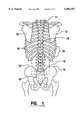
- FIG. 1 is a simplified schematic overview of a portion of the lower back skeletal structure of a patient with an outline of the sensor pad portion of the invention depicted in position thereover.
- FIG. 2 is a schematic view of the apparatus of the invention, comprising the sensor pad in connection with electronic apparatus including a computer and display unit.
- FIG. 3 is a schematic view of the screen of the display unit of the invention showing a full color bar matrix overlay in relation to the lower back skeletal anatomy of a human patient.
- FIG. 4 is a view partly in cross-section of a portion of the sensor pad of the invention, showing a single electrode and the electrical connection to the computer portion of the invention.
- FIG. 5 is an enlarged plan view only of the single electrode shown in FIG. 4.
- FIG. 6 is a cross-sectional view of a single electrode taken along the lines 6--6 of FIG. 5.
- FIG. 7 is a schematic view of the screen of the display unit of the invention depicting the location of a portion of the electrodes of the sensor pad as circles and showing several interconnecting color bars.
- FIG. 8 is a schematic view of the lower torso of a patient with the sensor pad held in position by a retaining belt and a support pad.
- FIG. 9 is a plan view with parts removed of the retaining belt of FIG. 8, showing the support pad.
- FIGS. 10-13 are schematic views of the screen of the display unit showing various configurations of color bar displays.
- FIG. 14 is a schematic diagram of skeletal anatomy associated with the lower back of a normal human patient.
- FIGS. 15-23 are schematic diagrams of various groups of musculature of a normal human patient shown in relation to the skeletal anatomy of FIG. 14.
- FIG. 24 is a schematic view of the apparatus of the invention, similar to that of FIGS. 2 and 4, in a modified showing of the interrelation of components of the invention.
- FIG. 25 is a schematic view of the components comprising the Analog Signal Conditioning Subsystem of FIG. 24.
- FIG. 26 is a schematic view of the components comprising the Signal Processing Subsystem of FIG. 24.
- FIG. 27 is a logic diagram showing the data flow in the software of the system.
- FIG. 28 is a chart of a portion of the software program of the invention, showing a header format.
- FIG. 29 is a chart of a portion of the software program of the invention, showing a listing of files developed therein.
- FIG. 30 is a chart of a portion of the software program of the invention, showing generally the Source File Structure.
- sensor pad 10 is a device for collecting electromyographic (EMG) signals from the underlying muscle structure supporting and providing movement to the spine 11.
- EMG electromyographic
- the muscle structure is a complicated array of muscles consisting of at least sixty-nine erector and intrinsic muscles in the thoracolumbosacral spine extending from about the tenth thoracic vertebrae 18 to the sacrum 20.
- EMG signals and their relation to muscle functions are well understood at the current state of investigations.
- Muscles are controlled by nerves, the latter transmitting an electrical signal to a particular muscle and causing contraction thereof.
- the muscle itself is a volume conductor reacting to the signal of the associated nerve.
- sensor pad 10 is a flat rectangular piece of siliconized rubber, approximately 0.062 inch thick, measuring about 12 ⁇ 12 inches and with a Durometer hardness on the order of 20 to 40.
- One source for sensor pad 10 is Fairprene Industrial Products, Inc. of Fairfield, Conn.
- Sensor pad 10 further comprises an array of sixty-three electrodes 28, preferably made of 316 L stainless steel. Electrodes 28 are arranged in a 7 ⁇ 9 pattern, with the electrodes in each row and column being spaced 1.162 inches apart on center. A central column 29 of nine electrodes 28 is located in the middle of sensor pad 10 to overlay the spine 11 of the patient, and three equally spaced parallel columns of nine electrodes each are positioned on either side of the central column 29. Similarly, a central row 30 of seven electrodes 28 is positioned near the center of sensor pad 10, and four parallel rows of seven electrodes each are positioned on either side of central row 30. Ground electrode 31, is a standard electrode preferably positioned on a wrist of the patient.
- All of the electrodes 28, are identical and one configuration is shown in greater detail in FIGS. 4-6 as comprising a pyramidal tipped, bolt-shaped structure having a head 32 and integral threaded shaft 34.
- Head 32 is circular and includes a plurality of pyramids 35 distributed substantially evenly and projecting outwardly of the upper surface of head 32 to form the patient-contacting surface of electrode 28.
- Head 32 is preferably 0.375 inches in diameter and has a thickness of 0.08 inches from the lower surface thereof at the junction with shaft 34, to the tips 36 of pyramids 35.
- Pyramids 35 are formed by grinding electrode head 32 in a series of parallel and orthogonal passes or by electromachining to produce a square pyramidal shape having an altitude of 0.042 inches, an angle of 90 degrees between opposing pyramid faces and culminating in a tip 36 having a radius of 0.005 inch. Tips 36 are spaced 0.094 inches from one another and in this embodiment of the invention, result in an electrode 28 having twelve pyramids 35 and tips 36 at the signal-collecting surface thereof. It has been determined that this configuration of electrode 28 is particularly useful in enhancing lower contact resistance when placed in position on a patient, thereby assuring better EMG signal reception and greater accuracy of the measurement.
- Each electrode 28 is mounted in an aperture in sensor pad 10 and retained in position by a nut 170 threaded to shaft 34.
- electrode 28 may have an unthreaded shaft 34 and be retained in position by a push connector.
- a solderless ring connector 38 is also received on shaft 34 and is firmly secured by outer nut 39 to provide an electrical interconnection with the signal gathering surface of electrode 28.
- An electrode wire 40 is crimped to connector 38 and each of the electrode wires 40 is routed over the surface of sensor pad 10 to a pigtail at the upper end of sensor pad 10 which terminates at a connector 41.
- Each electrode wire 40 is preferably a 30 gauge, multi strand, flexible copper wire which allows for some deformation of sensor pad 10 to conform to the lower back of a patient, while connector 41 allows for releasable connection of the sensor pad to the electrical circuitry to facilitate substitution of components of the apparatus of the invention.
- the edge to edge spacing of electrodes 28 in each column 29 and row 30 is 2.0 centimeters or approximately 0.79 inches. This has been determined to provide enough distance between electrodes 28 to result in a meaningful signal difference between electrodes.
- the electronic circuitry comprising preamplifier 23 is located near sensor pad 10 for conditioning and amplifying the signals received at electrodes 28.
- Electrode wire 40 is connected to buffer amplifier 42, and the signal in turn is routed to low pass filter 43 and high pass filter 44 for each electrode 28 of sensor pad 10. Conditioning of the signals preferably occurs closely adjacent the patient and avoids remote transmission of very low level signals in a background of randomly generated noise signals.
- Buffer amplifier 42 minimizes leakage current through the electrode and errors due to electrode impedance changes.
- High pass filter 44 serves as an anti-aliasing filter, and low pass filter 43 prevents saturation of analog to digital (A/D) converter 24 by offset voltages, such filters being well understood in the art.
- preamplifier 23 includes Buffer/Amplifier module 42 and Filter/Buffer module 105.
- Cable 45 connects the components of preamplifier 23 to analog to digital (A/D) converter 24 for transmission of the electrode signals for further processing and analysis.
- A/D analog to digital
- Sensor pad 10 is applied to the back of a patient by orienting certain of the electrodes 28 to the skeletal structure of the patient.
- the central electrode in the top row of electrode rows 30, i.e., electrode 46 is located over the spinous process of the tenth thoracic vertebrae 18.
- Two other landmarks are identified in a similar manner as the sensor pad 10 overlays the mid portion of the posterior superior iliac crest (PSIS).
- PSIS posterior superior iliac crest
- the second and fifth electrodes 33,37 respectively, in the center row of electrode rows 30 may be over the left PSIS and right PSIS.
- other landmarks may be used, such as an electrode overlying the fourth lumbar vertebrae, or other physiological reference point.
- This calibration information is then fed into the electronic apparatus 22 for appropriate adjustment of the voltage data received from electrodes 28 and subsequent visual display relative to predetermined displays of muscular anatomy appearing at display unit 26, in order to assure standardization of electrode placement.
- a type of lumbar support belt 49 encircles part of the lower torso of patient 48 and is retained in place by several straps 50 of non-elastic web culminating in quick release snaps 51 at the ends thereof for adjustment and securement.
- Belt 49 includes a pouch therein in which is disposed a molded foam pad 52.
- Pad 52 is generally rectangular in configuration and about one inch in thickness at its midpoint and tapering to about 1/8" thickness at its left and right edges.
- the pad has a curved inner surface generally conforming to the curvature of the lower torso of a typical patient 48 and overlying sensor pad 10 to press the latter into secure physical contact with patient 48 as straps 50 are adjusted.
- belt 49 is about two inches larger than the operative portion of sensor pad 10
- pad 52 is also slightly larger than sensor pad 10, thereby to overlap the latter and assure fairly uniform pressure over the entire area of sensor pad 10 and consistent readings from electrodes 28.
- pad 52 has three parts, namely parallel vertical sections 53 and a central stiffer section 54.
- Pad 52 is firm, yet flexible, and thicker in the central section 54 than in the outer sections 53 as described above. In this manner a better fit is made to accommodate the contour of the human back.
- Support belt 49 is preferably made of non-elastic nylon material as are straps 50 to achieve a secure and reliable connection to the patient 48.
- a conductive gel is applied to electrodes 28 to enhance conductivity of the interface between electrodes and patient 48, as is well known in the art.
- a conductive gel is applied to electrodes 28 to enhance conductivity of the interface between electrodes and patient 48, as is well known in the art.
- One suitable brand of water soluble gel is that manufactured by TECA, a subsidiary of Vickers Medical, Inc.
- sensor pad 10 Once sensor pad 10 has been located in position on a patient 48 and secured by support belt 49 and electrical interconnection made with electronic apparatus 22, the patient can be moved about and put through a series of different positions in order to develop a series of signal groups indicative of the underlying musculature. Typically, these positions are neutral, flexion, extension, left flexion, right flexion, left rotation, right rotation, sit, supine and prone, although various modifiers may be added to these positions. In each of the positions a scan of the electrodes 28 is made, each scan requiring only 1-10 seconds, and the signal information retained for later utilization in electronic apparatus 22.
- A/D converter 24 is a standard converter device, one suitable version being board no. AT-MIO-64-E3, manufactured by National Instruments Company.
- the data from sensor pad 10 is collected in pseudo differential fashion, each electrode 28 being sampled relative to reference electrode 61 located in the center of pad 10. Subtraction of electrical data yields the wave form between the two electrodes of interest and the wave form is subjected to a root mean square (RMS) analysis over a predetermined time interval to yield a discrete number indicative of the signal strength.
- RMS root mean square
- the RMS number is converted to a representative color indicia and that color indicia is displayed on the screen of display unit 26 in a location representative of the particular two electrodes 28 of interest.
- FIG. 7 representation of a portion of the screen 62 of display unit 26.
- the electrode positions are represented by circles with alphanumeric designations therein, with the seven columns of electrodes 28 designated from A-G and the nine rows designated from 1-9.
- various electrode positions are shown, for example, as C4, D5, E6 with D5 representative of the reference electrode 61 position.
- Intermediate computer generated light bars or line segments 63 interconnect various ones of the adjacent electrode positions, i.e., C5-D5 and C6-D5 to represent the pattern of image generated by computer 25 and displayed at screen 62 of display unit 26.
- FIG. 3 A full pattern display is shown in FIG. 3 wherein the screen 62 of display unit 26 shows the full array of light bars 63 interconnecting all of the electrode 28 positions, in a matrix overlying a display of the lower back skeletal anatomy 90 of the patient 48.
- This view demonstrates the spatial relationship among the locations of electrodes 28, the visual display of light bars 63 and the patient 48 anatomy 90 in a manner that can be readily visualized and utilized by the examining physician. It will be described in greater detail hereinafter that the light bar 63 display can be adjusted or modified by the physician, or automatically by the computer to produce effects including a more limited visual display of light bars 63, or variations in intensity, hue or colorization thereof to enhance the desired display.
- color bar images are produced on display unit 26 in positions delimited by and corresponding to the positions of the electrodes 28 on sensor pad 10. Also superimposed on display unit 26 is a graphical depiction of the musculature of the lower back of patient 48 with correlation between the two being achieved by the registration process previously described where a sensor pad is located relative to the tenth thoracic vertebrae 18 and the PSIS identifying crests 12, 14.
- the diagrams of the musculature of FIGS. 15-23 may be shown at the screen of display unit 26 as a series of images, each representative of certain muscle groups of the lower back of patient 48 so that the attending physician might make a correlation between the colors which represent the strength of contraction of the muscle underneath the electrode and the particular muscles or muscle groups, and discern what muscle is causing the particular colorization patterns being produced. It is apparent as well, that it would be possible to program computer 25 to recognize abnormal signals from the electrodes 28 being polled to provide some other indication of the abnormal situation using different evaluation techniques. It is also apparent that the signals collected from electrodes 28 can be stored in a database and processed in different ways, perhaps at later times or printed out in hard copy, if this is a desired result. The capture of data from all of the electrodes 28 occurs substantially simultaneously and is stored in computer 25 for manipulation in a myriad of possible ways, only certain of which are described herein.
- each electrode 28 is scanned relative to reference electrode 61 to develop a signal representative of the voltage level detected at the site of the particular electrode, and data representative of the signal retained in computer 25.
- each signal may be compared to that of other electrodes to develop signal patterns representative of the muscle condition being evaluated.
- FIG. 10 is a representation of signals developed at sensor pad 10 when only a depiction of a discrete color dot is made at the location of each electrode 28, with no showing of color bars. This display might be most useful in achieving a desired registration between electrode 28 display and the skeletal structure 90 display.
- FIG. 11 describes a first variation for analysis of the signals where the signal of each electrode 28 in the first row 64 is compared to the corresponding electrode 28 in the same column, in the second row 65 to develop a resultant signal, represented at display unit 26 as a bar 66 joining the location of the particular electrodes.
- a resultant signal represented at display unit 26 as a bar 66 joining the location of the particular electrodes.
- Such arrangement of color bars 66 may be displayed juxtaposed to patterns of muscle structure as previously described, and likely is more useful in displaying an association with muscles or muscle groups which are oriented generally vertically in the back of the patient.
- FIGS. 12 and 13 represent yet other variations of signal analysis wherein different herringbone patterns of signal are derived.
- the signal of center electrode 70 in the second row, center column (D2) is compared with electrodes 71, 72 in the first row and adjacent columns (C1) (E1) to develop intermediate color bars 74, 75 respectively, indicative of the comparison of the electrode signals. Further color bars corresponding to bars 74, 75 are developed throughout the array of electrodes 28 to achieve an overall pattern for display at display unit 26. Again, only a portion of the display is depicted in FIG. 12, for purposes of clarity.
- FIG. 13 is yet another variation of a display that may be produced using this technique of monitoring.
- an inverted herringbone pattern consisting of color bars 78 is achieved when the signals from electrodes 28 are compared in the described pattern.
- electrode 79 in the first row, center column (D1) is compared to electrodes 80, 81 in the second row in adjacent columns (C2) (E2) to produce the intermediate color bars 78.
- a colored herringbone pattern of color bars 78 is achieved for comparison with muscle pattern displays shown in association therewith.
- the resultant electrical signals from electrodes 28 and the resultant color information can be shown at display unit 26 in different formats to emphasize the relationship between developed signals and the underlying muscle structure.
- the images of differing muscle structures can be shown in association with the color patterns as directed by the physician to provide a correlation between the colorization and the abnormal muscle elements.
- Electrode subsystem 100 comprises the array of sixty-three electrodes 28, only a few of which are shown and labeled as A, B, F, G, Ref. and Gnd. in correspondence with previous descriptions.
- Wires 40 connect electrodes 28 to buffer amplifier 42, shown in block form on FIG. 24 and in more detail in FIG. 25.
- a long shielded interconnect cable 104 connects the outputs of buffer amplifier 42 to more remotely located Filter/Buffer module 105 which includes low and high pass filters 43, 44.
- a short shield cable 45 completes the analog signal portion, being connected to analog to digital converter card 24 in computer 25, the latter components being essential parts of the signal processing subsystem 102.
- a single continuous shield path depicted by dashed lines 107, is established between Buffer/Amplifier module 42 and computer 25, assuring that minimal interference is generated in the signals of interest from extraneous sources.
- the enclosures used for the Filter/Buffer module 105 and the Buffer/Amplifier module 42 are shielded with a layer of conductive material. All enclosure shields are connected in series with the interconnect cable shields, resulting in a single continuous shield path from the Buffer/Amplifier input connector to the data acquisition computer 25 chassis ground.
- the array of electrodes 28 mounted on sensor pad 10, as previously described, must conform to the human back, ensure consistent electrode impedance with the skin, not interfere substantially with patient movement, and be easy to clean and reuse.
- the electrodes 28 are preferably in a nine row by seven column configuration and the sensor pad 10 is preferably held in place with a fabric brace with or without pressure sensitive adhesive.
- the analog signal conditioning subsystem 101 provides buffering, voltage amplification and analog filtering for the array of electrodes 28.
- One electrode in the array is designated as the reference electrode 61, and all other electrode voltages are measured with respect to the reference electrode 61.
- Each of the electrode 28 signals is connected by way of wires 40 to high impedance, unity gain buffer amplifiers 108 by way of a 10K Ohm series resistor 109.
- the purpose of resistor 109 is to provide a measure of resistive isolation for safety purposes, as well as to increase the electrostatic discharge (ESD) immunity of the amplifier.
- each channel has a dedicated high gain instrumentation amplifier 110.
- the inverting input of each instrumentation amplifier 110 is connected to the buffered signal from the reference electrode channel as shown by connector 111.
- the output of each instrumentation amplifier 110 represents the voltage of a given electrode with respect to the reference electrode 61.
- RC networks 112 connected to the inputs of the instrumentation amplifier 110 serve as low pass filters to block unwanted high frequency signals.
- the outputs of the instrumentation amplifiers 110 feed into unity-gain, line-driver circuits 114 that are capable of driving the capacitive load of the long shielded interconnect cable 104, without oscillation.
- the ground electrode 31 is connected to the patient and is connected to ground through a resistor. In the preferred embodiment electrode 31 is connected to the analog signal ground on the digital converter card through a one million Ohm resistance.
- the preferred form of the analog to digital converter card 24, is a sixty-four channel multiplexed converter capable of operating in pseudo-differential input mode.
- the Buffer/Amplifier module 42 and Filter/Buffer module 105 are each connected to ground as represented by line 106.
- Each of the sixty-three signal inputs into Filter/Buffer 105, via cable 104, is connected to a second order active low pass filter 43.
- the output of low pass filter 43 is connected to the input of first order, high pass filter 44.
- the output of each high pass filter 44 is connected to unity gain buffer 115 that is capable of driving the capacitive load of the analog to digital converter card 24 interconnect cable 45, without oscillation.
- Electronic power for Filter/Buffer module 105 is provided by an external linear power supply.
- Filter/Buffer module 105 provides power for Buffer/Amplifier module 42 via the interconnect cable 104.
- Ground sense line 106 from the Buffer/Amplifier modules 42 passes directly through the Filter/Buffer module 105.
- Signal processing subsystem 102 is shown in block diagram form in FIG. 26 and consists of the major elements of a digital filter 120, voltage differencer 121 and RMS calculator 122. First, digital filtering techniques are used to reduce noise on the measured signal. Next, a voltage differencer 121 determines the voltage waveform between all adjacent electrodes 28. Finally, the root-mean-square (RMS) voltage between all adjacent electrodes is calculated and used to characterize the level of muscle activity between adjacent electrodes.
- the signal processing subsystem is preferably implemented in software on a PC-compatible computer 25.
- the digital signal conditioning system consists of high pass, low pass and band-cut digital filters incorporated into the data analysis software.
- the high and low pass filters are designed to reject signals outside of the frequency range of interest, and have amplitude rolloffs of 80 dB/decade.
- the primary purpose of these digital filters is to block common-mode error signals introduced near the corner frequencies of the analog filters.
- the band-cut or notch filter drastically reduces 60 Hz signals, in order to eliminate unwanted pickup of power line emissions.
- oversampling is used which interpolates additional pseudo sample points between actual sample points to improve performance of filters, for example to achieve good frequency discrimination in the 60 Hz notch filter. In one preferred embodiment 10 ⁇ oversampling is used.
- the output of the electrode voltage data acquisition subsystem consists of a set of voltage waveforms of each electrode 28 with respect to a particular reference electrode.
- the voltage differencer 121 computes, the voltage waveform between each pair of adjacent electrodes (vertically, horizontally and diagonally) by differencing the voltage waveforms for the two adjacent electrodes.
- RMS calculator 122 provides the RMS value of each adjacent electrode pair waveform as a scalar number which is computed from the waveform using a conventional RMS calculation.
- the user display subsystem 26 presents the processed data to the practitioner in a readily understandable format.
- the data is displayed as images on a screen or other visual output device.
- a digitized illustration of a muscle layer in the human back as shown in FIGS. 14-23 is used as the background of the image.
- the user may select any muscle layer as the image background.
- a computer generated image 125 of the processed electrode 28 data is overlaid on the selected background illustration, and is spatially registered to that image.
- the electrode data image 125 consists of colored lines or light bars 63 drawn between the locations of each of adjacent electrodes 28, which are at each intersection 128 of each of the seven vertical columns and nine horizontal rows of light bars 63 as shown in FIG. 3 and as has been previously described.
- the color of each line 63 indicates the value of the RMS voltage between the adjacent electrodes.
- the user can dynamically specify a maximum RMS value and a minimum RMS value, which are used to map voltages to colors.
- the resulting display is thus a false-color RMS, voltage gradient field display, and is overlaid on and registered to the underlying muscle layer illustration.
- the software architecture of the signal processing system 102 is shown schematically in FIG. 27 as a diagram of the main data flow in the software. Essentially, this is a linear flow of computations, each of which takes a datum or file as input and generates a datum or file as output. Three types of data files are generated and stored and once created may be opened and displayed many times at later dates.
- the data files are described as well in FIG. 29 and comprise the Analog to Digital (A2D) file 130, Voltage (DAT) file 132 and Root Mean Square (RMS) file 134.
- A2D Analog to Digital
- DAT Voltage
- RMS Root Mean Square
- header 135 for each of the files, 130, 132, 134 is depicted in FIG. 28 and in one embodiment contains information in an identical ASCII header format consisting of version information 152, patient information 154, which are the vital statistics on the patient being diagnosed, pad information 155 which provides specifics of sensor pad 10, calibration information 156, data acquisition settings 157 and display settings 158.
- the calibration information is derived after the sensor pad 10 location is determined on the back of the patient, being input by the operator to specify where certain parts of the patient's back are in relation to the electrodes on the pad, as previously described.
- the A2D files 130 contain the actual analog to digital values at the output of analog to digital converter 24 which are collected during a test.
- Computer 25 scans all electrode channels rapidly enough to reconstruct the analog signal at all frequencies of interest. In one embodiment the minimum frequency of interest is about 30 Hz and the maximum about 150 Hz.
- the structure of the A2D files 130 is shown in FIG. 29 with each scan sample being stored in a two byte word in little endian format.
- the files 130 contain the analog to digital value and a header 135.
- the voltage files 132 contain the voltage data from a test, after it has been converted from analog to digital values to voltages and signal conditioning filters have been applied.
- the voltage files 132 of this embodiment also contain the header 135 followed by the voltage values in the format shown in FIG. 29, each sample being stored as an IEEE double floating point value.
- the RMS files 134 contain the RMS values of the differences between the voltage waveforms of adjacent electrodes 28. During display of an RMS file 134, the values can be mapped to colors and displayed as colored line segments or color bars 63 at display unit 26. Again, the RMS files 134 contain header 135 followed by the RMS information. The RMS voltage difference is calculated for each pair of adjacent electrodes 28. The row and column position of each of the two electrodes are also stored in the format described in FIG. 29. Also included is information of the minimum and maximum RMS value in each scan and the total number of adjacent electrode pairs.
- computer 25 generates signals to capture samples 140 from data acquisition board 24 at the input to computer 25 to create raw data or A2D files 130.
- Computer 25 then acts to convert the signals to voltage at 142 and run signal conditioning filters 144 to create voltage files 132.
- Computer 25 is then programmed to compute the RMS values at 146 and create the RMS data file 134.
- computer 25 operates to scale and compute color values at 148, and then to draw the RMS data at 150 and eventually provide the color bar matrix 125 depicted in FIG. 3.
- the general architecture for the software operated in computer 25 can be seen from the source file 160 structure depicted in FIG. 30.
- the document view and visual interface 161 contain main initialization, menu and toolbar commands, message handlers and document/view commands. Dialog popups 162 allow for entering patient information, calibration information and the like and for editing various parameters. Further files include data acquisition, filtering and calculation 163, reading and writing header information and data 164, utilities 165, and bitmaps, icons and resource files 166. These routines are fairly typical for handling the information flow in the ways specified previously and are well understood in the art, not requiring detailed description herein.
- the apparatus of the invention might be applied to areas of human anatomy other than the lower back musculature, most obviously to mid-back, upper back or neck areas. Still further, it would be feasible to apply the teachings of the invention to the extremities of the human patient or even to areas of the head.
- the present invention may also be applied to the analysis of signals from other types of sensors and the techniques described herein used in the diagnosis and treatment of other conditions. While the preferred form of the invention is used in the diagnosis of conditions in human beings, the techniques and apparatus of the invention may also find applicability in diagnostic and treatment activities related to patients which comprise other living organisms.
Abstract
Description
Claims (17)
Priority Applications (1)
| Application Number | Priority Date | Filing Date | Title |
|---|---|---|---|
| US09/059,783 US6002957A (en) | 1997-04-15 | 1998-04-14 | EMG electrode array support belt |
Applications Claiming Priority (2)
| Application Number | Priority Date | Filing Date | Title |
|---|---|---|---|
| US4309297P | 1997-04-15 | 1997-04-15 | |
| US09/059,783 US6002957A (en) | 1997-04-15 | 1998-04-14 | EMG electrode array support belt |
Publications (1)
| Publication Number | Publication Date |
|---|---|
| US6002957A true US6002957A (en) | 1999-12-14 |
Family
ID=26720040
Family Applications (1)
| Application Number | Title | Priority Date | Filing Date |
|---|---|---|---|
| US09/059,783 Expired - Lifetime US6002957A (en) | 1997-04-15 | 1998-04-14 | EMG electrode array support belt |
Country Status (1)
| Country | Link |
|---|---|
| US (1) | US6002957A (en) |
Cited By (52)
| Publication number | Priority date | Publication date | Assignee | Title |
|---|---|---|---|---|
| US6477397B1 (en) * | 1999-05-20 | 2002-11-05 | Polar Electro Oy | Electrode structure |
| US20030069514A1 (en) * | 2001-10-05 | 2003-04-10 | Brody Lee Richard | Apparatus for routing electromyography signals |
| US20040054275A1 (en) * | 1998-10-05 | 2004-03-18 | Advanced Imaging Systems, Inc. | EMG electrode apparatus and positioning system |
| WO2004091389A1 (en) * | 2003-04-16 | 2004-10-28 | Université Libre de Bruxelles | A non-invasive sensor to visually analyze the level of muscle activity |
| US20050165316A1 (en) * | 2004-01-23 | 2005-07-28 | Lowery Michael G. | Method for detecting artifacts in data |
| US20080046051A1 (en) * | 2006-08-21 | 2008-02-21 | Skubitz Sean P | Novel features for routing conductors in medical electrical lead electrode assemblies |
| US20080046049A1 (en) * | 2006-08-21 | 2008-02-21 | Skubitz Sean P | Novel assembly methods for medical electrical leads |
| US20080046050A1 (en) * | 2006-08-21 | 2008-02-21 | Skubitz Sean P | Novel medical electrode mounting |
| US7420472B2 (en) | 2005-10-16 | 2008-09-02 | Bao Tran | Patient monitoring apparatus |
| US20080275316A1 (en) * | 2007-05-04 | 2008-11-06 | Reproductive Research Technologies, Lp | Skin impedance matching system and method for skin/electrode interface |
| US20090036792A1 (en) * | 2005-09-12 | 2009-02-05 | Deluca Carlo J | Sensor system for detecting and processing EMG signals |
| US7502498B2 (en) | 2004-09-10 | 2009-03-10 | Available For Licensing | Patient monitoring apparatus |
| US7539533B2 (en) | 2006-05-16 | 2009-05-26 | Bao Tran | Mesh network monitoring appliance |
| US7539532B2 (en) | 2006-05-12 | 2009-05-26 | Bao Tran | Cuffless blood pressure monitoring appliance |
| US7558622B2 (en) | 2006-05-24 | 2009-07-07 | Bao Tran | Mesh network stroke monitoring appliance |
| US20110028823A1 (en) * | 2009-07-28 | 2011-02-03 | Gilmore L Donald | Biomedical electrode configuration for suppressing movement artifact |
| US7987001B2 (en) | 2007-01-25 | 2011-07-26 | Warsaw Orthopedic, Inc. | Surgical navigational and neuromonitoring instrument |
| US20110190652A1 (en) * | 2010-01-29 | 2011-08-04 | Reproductive Research Technologies, Llp | System and method for acquiring and displaying uterine emg signals |
| US20110237972A1 (en) * | 2010-03-23 | 2011-09-29 | Robert Garfield | Noninvasive measurement of uterine emg propagation and power spectrum frequency to predict true preterm labor and delivery |
| US20120035496A1 (en) * | 2009-04-24 | 2012-02-09 | Denison Timothy J | Bladder sensing using impedance and posture |
| US20120226330A1 (en) * | 2009-11-05 | 2012-09-06 | Koninklijke Philips Electronics N.V. | Electrical muscle stimulation |
| US8323189B2 (en) | 2006-05-12 | 2012-12-04 | Bao Tran | Health monitoring appliance |
| US8374673B2 (en) | 2007-01-25 | 2013-02-12 | Warsaw Orthopedic, Inc. | Integrated surgical navigational and neuromonitoring system having automated surgical assistance and control |
| US8461988B2 (en) | 2005-10-16 | 2013-06-11 | Bao Tran | Personal emergency response (PER) system |
| US8500636B2 (en) | 2006-05-12 | 2013-08-06 | Bao Tran | Health monitoring appliance |
| US8684922B2 (en) | 2006-05-12 | 2014-04-01 | Bao Tran | Health monitoring system |
| US8684900B2 (en) | 2006-05-16 | 2014-04-01 | Bao Tran | Health monitoring appliance |
| US8750971B2 (en) | 2007-05-24 | 2014-06-10 | Bao Tran | Wireless stroke monitoring |
| US8753334B2 (en) | 2006-05-10 | 2014-06-17 | Covidien Ag | System and method for reducing leakage current in an electrosurgical generator |
| US8968195B2 (en) | 2006-05-12 | 2015-03-03 | Bao Tran | Health monitoring appliance |
| US8989835B2 (en) | 2012-08-17 | 2015-03-24 | The Nielsen Company (Us), Llc | Systems and methods to gather and analyze electroencephalographic data |
| EP2406698A4 (en) * | 2009-03-13 | 2015-05-06 | Microsoft Technology Licensing Llc | Wearable electromyography-based controllers for human-computer interface |
| US9060683B2 (en) | 2006-05-12 | 2015-06-23 | Bao Tran | Mobile wireless appliance |
| US9095267B2 (en) | 2011-12-22 | 2015-08-04 | Modular Bionics Inc. | Neural interface device and insertion tools |
| US20150273600A1 (en) * | 2012-10-25 | 2015-10-01 | Applied Materials, Inc. | Electro discharge machining system and method of operation thereof |
| US9320450B2 (en) | 2013-03-14 | 2016-04-26 | The Nielsen Company (Us), Llc | Methods and apparatus to gather and analyze electroencephalographic data |
| US20160143592A1 (en) * | 2014-11-19 | 2016-05-26 | Suunto Oy | Wearable sports monitoring equipment for measuring heart rate or muscular activity and relating method |
| US9498128B2 (en) | 2012-11-14 | 2016-11-22 | MAD Apparel, Inc. | Wearable architecture and methods for performance monitoring, analysis, and feedback |
| US9622703B2 (en) | 2014-04-03 | 2017-04-18 | The Nielsen Company (Us), Llc | Methods and apparatus to gather and analyze electroencephalographic data |
| US9820658B2 (en) | 2006-06-30 | 2017-11-21 | Bao Q. Tran | Systems and methods for providing interoperability among healthcare devices |
| US9865176B2 (en) | 2012-12-07 | 2018-01-09 | Koninklijke Philips N.V. | Health monitoring system |
| US9913611B2 (en) | 2014-11-10 | 2018-03-13 | MAD Apparel, Inc. | Garment integrated sensing system and method |
| US10086192B2 (en) | 2016-07-07 | 2018-10-02 | Modular Bionics Inc. | Neural interface insertion and retraction tools |
| US10292652B2 (en) | 2013-11-23 | 2019-05-21 | MAD Apparel, Inc. | System and method for monitoring biometric signals |
| US10321832B2 (en) | 2013-11-23 | 2019-06-18 | MAD Apparel, Inc. | System and method for monitoring biometric signals |
| US10398376B2 (en) | 2014-06-17 | 2019-09-03 | MAD Apparel, Inc. | Garment integrated electrical interface system and method of manufacture |
| US10506974B2 (en) | 2016-03-14 | 2019-12-17 | The Nielsen Company (Us), Llc | Headsets and electrodes for gathering electroencephalographic data |
| US10617354B2 (en) | 2014-04-29 | 2020-04-14 | MAD Apparel, Inc. | Biometric electrode system and method of manufacture |
| US10674914B1 (en) | 2015-06-24 | 2020-06-09 | Modular Bionics Inc. | Wireless neural interface system |
| US11065439B1 (en) | 2017-12-11 | 2021-07-20 | Modular Bionics Inc. | Conforming modular neural interface system |
| CN113425314A (en) * | 2021-05-26 | 2021-09-24 | 上海理工大学 | Array type high-density surface myoelectricity acquisition device and myoelectricity acquisition method |
| US11219396B2 (en) | 2013-11-23 | 2022-01-11 | MAD Apparel, Inc. | System and method for monitoring biometric signals |
Citations (25)
| Publication number | Priority date | Publication date | Assignee | Title |
|---|---|---|---|---|
| US3525330A (en) * | 1966-02-24 | 1970-08-25 | Lockheed Aircraft Corp | Surgical garment prescription method and apparatus |
| US3612061A (en) * | 1969-02-20 | 1971-10-12 | Inst Of Medical Sciences The | Flexible cutaneous electrode matrix |
| US3641993A (en) * | 1970-04-23 | 1972-02-15 | Prototypes Inc | Nonlinear electromyograph |
| US4026300A (en) * | 1975-03-14 | 1977-05-31 | Liberty Mutual | Method and apparatus for interfacing to nerves |
| US4031882A (en) * | 1975-07-14 | 1977-06-28 | Liberty Mutual Insurance Company | Apparatus for interfacing to anatomic signal sources |
| US4033333A (en) * | 1975-12-10 | 1977-07-05 | Combined Scientific Resources Corporation | Electrode arrangement for taking electrocardiograms |
| US4046141A (en) * | 1975-07-14 | 1977-09-06 | Liberty Mutual Insurance Company | Method and apparatus for interfacing to anatomic signal sources |
| US4381012A (en) * | 1980-09-24 | 1983-04-26 | Wallant International Trade, Inc. | Electrode placement device |
| US4387723A (en) * | 1980-12-09 | 1983-06-14 | Wisconsin Alumni Research Foundation | Method and apparatus for determining the level of neuromuscular block in a patient |
| US4570225A (en) * | 1983-07-22 | 1986-02-11 | Lundy Research Laboratories, Inc. | Method and apparatus for characterizing the unknown state of a physical system |
| US4572197A (en) * | 1982-07-01 | 1986-02-25 | The General Hospital Corporation | Body hugging instrumentation vest having radioactive emission detection for ejection fraction |
| US4611284A (en) * | 1983-09-09 | 1986-09-09 | The Board Of Trustees Of The Leland Stanford, Jr. University | Method for decomposing an electromyogram into individual motor unit action potentials |
| US4667513A (en) * | 1981-03-18 | 1987-05-26 | Konno Yoshio | Method and apparatus for detecting muscle fatigue |
| US4709704A (en) * | 1984-03-06 | 1987-12-01 | The Kendall Company | Monitoring device for bio-signals |
| US4751928A (en) * | 1986-06-11 | 1988-06-21 | Slovenska Akdemie Vied Bratislava | Multielectrode system for surface registering of electric heart potentials |
| US4967038A (en) * | 1986-12-16 | 1990-10-30 | Sam Techology Inc. | Dry electrode brain wave recording system |
| US5085226A (en) * | 1990-05-30 | 1992-02-04 | Trustees Of Boston University | Force monitoring apparatus for back muscles |
| US5085225A (en) * | 1990-05-30 | 1992-02-04 | Trustees Of Boston University | Electrode matrix for monitoring back muscles |
| US5163440A (en) * | 1990-05-30 | 1992-11-17 | Trustees Of Boston University | Method for monitoring performance of back muscles |
| US5224479A (en) * | 1991-06-21 | 1993-07-06 | Topy Enterprises Limited | ECG diagnostic pad |
| US5462065A (en) * | 1994-08-17 | 1995-10-31 | Cusimano; Maryrose | Integrated movement analyziing system |
| US5483970A (en) * | 1992-12-09 | 1996-01-16 | Hygeia Biomedical Research Inc. | Apparatus and methods for the diagnosis of labor |
| US5645073A (en) * | 1989-07-31 | 1997-07-08 | Synectics Medical Ab | Method and an apparatus for use in electromyography to determine risk of muscular disorder |
| US5662118A (en) * | 1995-06-01 | 1997-09-02 | Skubick; Daniel Lewis | System for diagnosing musculoskeletal disorders |
| US5704368A (en) * | 1994-06-17 | 1998-01-06 | Gram Corporation | Method of, and apparatus for, measuring electrogastrogram and intestinal electrogram |
-
1998
- 1998-04-14 US US09/059,783 patent/US6002957A/en not_active Expired - Lifetime
Patent Citations (25)
| Publication number | Priority date | Publication date | Assignee | Title |
|---|---|---|---|---|
| US3525330A (en) * | 1966-02-24 | 1970-08-25 | Lockheed Aircraft Corp | Surgical garment prescription method and apparatus |
| US3612061A (en) * | 1969-02-20 | 1971-10-12 | Inst Of Medical Sciences The | Flexible cutaneous electrode matrix |
| US3641993A (en) * | 1970-04-23 | 1972-02-15 | Prototypes Inc | Nonlinear electromyograph |
| US4026300A (en) * | 1975-03-14 | 1977-05-31 | Liberty Mutual | Method and apparatus for interfacing to nerves |
| US4031882A (en) * | 1975-07-14 | 1977-06-28 | Liberty Mutual Insurance Company | Apparatus for interfacing to anatomic signal sources |
| US4046141A (en) * | 1975-07-14 | 1977-09-06 | Liberty Mutual Insurance Company | Method and apparatus for interfacing to anatomic signal sources |
| US4033333A (en) * | 1975-12-10 | 1977-07-05 | Combined Scientific Resources Corporation | Electrode arrangement for taking electrocardiograms |
| US4381012A (en) * | 1980-09-24 | 1983-04-26 | Wallant International Trade, Inc. | Electrode placement device |
| US4387723A (en) * | 1980-12-09 | 1983-06-14 | Wisconsin Alumni Research Foundation | Method and apparatus for determining the level of neuromuscular block in a patient |
| US4667513A (en) * | 1981-03-18 | 1987-05-26 | Konno Yoshio | Method and apparatus for detecting muscle fatigue |
| US4572197A (en) * | 1982-07-01 | 1986-02-25 | The General Hospital Corporation | Body hugging instrumentation vest having radioactive emission detection for ejection fraction |
| US4570225A (en) * | 1983-07-22 | 1986-02-11 | Lundy Research Laboratories, Inc. | Method and apparatus for characterizing the unknown state of a physical system |
| US4611284A (en) * | 1983-09-09 | 1986-09-09 | The Board Of Trustees Of The Leland Stanford, Jr. University | Method for decomposing an electromyogram into individual motor unit action potentials |
| US4709704A (en) * | 1984-03-06 | 1987-12-01 | The Kendall Company | Monitoring device for bio-signals |
| US4751928A (en) * | 1986-06-11 | 1988-06-21 | Slovenska Akdemie Vied Bratislava | Multielectrode system for surface registering of electric heart potentials |
| US4967038A (en) * | 1986-12-16 | 1990-10-30 | Sam Techology Inc. | Dry electrode brain wave recording system |
| US5645073A (en) * | 1989-07-31 | 1997-07-08 | Synectics Medical Ab | Method and an apparatus for use in electromyography to determine risk of muscular disorder |
| US5085226A (en) * | 1990-05-30 | 1992-02-04 | Trustees Of Boston University | Force monitoring apparatus for back muscles |
| US5163440A (en) * | 1990-05-30 | 1992-11-17 | Trustees Of Boston University | Method for monitoring performance of back muscles |
| US5085225A (en) * | 1990-05-30 | 1992-02-04 | Trustees Of Boston University | Electrode matrix for monitoring back muscles |
| US5224479A (en) * | 1991-06-21 | 1993-07-06 | Topy Enterprises Limited | ECG diagnostic pad |
| US5483970A (en) * | 1992-12-09 | 1996-01-16 | Hygeia Biomedical Research Inc. | Apparatus and methods for the diagnosis of labor |
| US5704368A (en) * | 1994-06-17 | 1998-01-06 | Gram Corporation | Method of, and apparatus for, measuring electrogastrogram and intestinal electrogram |
| US5462065A (en) * | 1994-08-17 | 1995-10-31 | Cusimano; Maryrose | Integrated movement analyziing system |
| US5662118A (en) * | 1995-06-01 | 1997-09-02 | Skubick; Daniel Lewis | System for diagnosing musculoskeletal disorders |
Cited By (120)
| Publication number | Priority date | Publication date | Assignee | Title |
|---|---|---|---|---|
| US20040054275A1 (en) * | 1998-10-05 | 2004-03-18 | Advanced Imaging Systems, Inc. | EMG electrode apparatus and positioning system |
| US6856833B2 (en) * | 1998-10-05 | 2005-02-15 | Advanced Imaging Systems, Inc. | EMG electrode apparatus and positioning system |
| US6477397B1 (en) * | 1999-05-20 | 2002-11-05 | Polar Electro Oy | Electrode structure |
| US20030069514A1 (en) * | 2001-10-05 | 2003-04-10 | Brody Lee Richard | Apparatus for routing electromyography signals |
| US6965794B2 (en) * | 2001-10-05 | 2005-11-15 | Fasstech, Inc. | Apparatus for routing electromyography signals |
| US20060094975A1 (en) * | 2003-04-16 | 2006-05-04 | Mario Manto | Non-invasive sensor to analyze visually the level of muscle activity |
| WO2004091389A1 (en) * | 2003-04-16 | 2004-10-28 | Université Libre de Bruxelles | A non-invasive sensor to visually analyze the level of muscle activity |
| US7254425B2 (en) | 2004-01-23 | 2007-08-07 | Abbott Laboratories | Method for detecting artifacts in data |
| US20050165316A1 (en) * | 2004-01-23 | 2005-07-28 | Lowery Michael G. | Method for detecting artifacts in data |
| US7502498B2 (en) | 2004-09-10 | 2009-03-10 | Available For Licensing | Patient monitoring apparatus |
| US20090036792A1 (en) * | 2005-09-12 | 2009-02-05 | Deluca Carlo J | Sensor system for detecting and processing EMG signals |
| US8531291B2 (en) | 2005-10-16 | 2013-09-10 | Bao Tran | Personal emergency response (PER) system |
| US8747336B2 (en) | 2005-10-16 | 2014-06-10 | Bao Tran | Personal emergency response (PER) system |
| US7420472B2 (en) | 2005-10-16 | 2008-09-02 | Bao Tran | Patient monitoring apparatus |
| US8461988B2 (en) | 2005-10-16 | 2013-06-11 | Bao Tran | Personal emergency response (PER) system |
| US8753334B2 (en) | 2006-05-10 | 2014-06-17 | Covidien Ag | System and method for reducing leakage current in an electrosurgical generator |
| US8475368B2 (en) | 2006-05-12 | 2013-07-02 | Bao Tran | Health monitoring appliance |
| US9215980B2 (en) | 2006-05-12 | 2015-12-22 | Empire Ip Llc | Health monitoring appliance |
| US8500636B2 (en) | 2006-05-12 | 2013-08-06 | Bao Tran | Health monitoring appliance |
| US8747313B2 (en) | 2006-05-12 | 2014-06-10 | Bao Tran | Health monitoring appliance |
| US8727978B2 (en) | 2006-05-12 | 2014-05-20 | Bao Tran | Health monitoring appliance |
| US8708903B2 (en) | 2006-05-12 | 2014-04-29 | Bao Tran | Patient monitoring appliance |
| US9820657B2 (en) | 2006-05-12 | 2017-11-21 | Koninklijke Philips N.V. | Mobile wireless appliance |
| US8425415B2 (en) | 2006-05-12 | 2013-04-23 | Bao Tran | Health monitoring appliance |
| US9801542B2 (en) | 2006-05-12 | 2017-10-31 | Koninklijke Philips N.V. | Health monitoring appliance |
| US8684922B2 (en) | 2006-05-12 | 2014-04-01 | Bao Tran | Health monitoring system |
| US7539532B2 (en) | 2006-05-12 | 2009-05-26 | Bao Tran | Cuffless blood pressure monitoring appliance |
| US8968195B2 (en) | 2006-05-12 | 2015-03-03 | Bao Tran | Health monitoring appliance |
| US8652038B2 (en) | 2006-05-12 | 2014-02-18 | Bao Tran | Health monitoring appliance |
| US9060683B2 (en) | 2006-05-12 | 2015-06-23 | Bao Tran | Mobile wireless appliance |
| US8328718B2 (en) | 2006-05-12 | 2012-12-11 | Bao Tran | Health monitoring appliance |
| US8323189B2 (en) | 2006-05-12 | 2012-12-04 | Bao Tran | Health monitoring appliance |
| US8323188B2 (en) | 2006-05-16 | 2012-12-04 | Bao Tran | Health monitoring appliance |
| US7539533B2 (en) | 2006-05-16 | 2009-05-26 | Bao Tran | Mesh network monitoring appliance |
| US8684900B2 (en) | 2006-05-16 | 2014-04-01 | Bao Tran | Health monitoring appliance |
| US9028405B2 (en) | 2006-05-16 | 2015-05-12 | Bao Tran | Personal monitoring system |
| US9107586B2 (en) | 2006-05-24 | 2015-08-18 | Empire Ip Llc | Fitness monitoring |
| US8449471B2 (en) | 2006-05-24 | 2013-05-28 | Bao Tran | Health monitoring appliance |
| US8764651B2 (en) | 2006-05-24 | 2014-07-01 | Bao Tran | Fitness monitoring |
| US7558622B2 (en) | 2006-05-24 | 2009-07-07 | Bao Tran | Mesh network stroke monitoring appliance |
| US9351640B2 (en) | 2006-06-30 | 2016-05-31 | Koninklijke Philips N.V. | Personal emergency response (PER) system |
| US10729336B1 (en) | 2006-06-30 | 2020-08-04 | Bao Tran | Smart watch |
| US8525687B2 (en) | 2006-06-30 | 2013-09-03 | Bao Tran | Personal emergency response (PER) system |
| US8525673B2 (en) | 2006-06-30 | 2013-09-03 | Bao Tran | Personal emergency response appliance |
| US11051704B1 (en) | 2006-06-30 | 2021-07-06 | Bao Tran | Smart watch |
| US10610111B1 (en) | 2006-06-30 | 2020-04-07 | Bao Tran | Smart watch |
| US9204796B2 (en) | 2006-06-30 | 2015-12-08 | Empire Ip Llc | Personal emergency response (PER) system |
| US9775520B2 (en) | 2006-06-30 | 2017-10-03 | Empire Ip Llc | Wearable personal monitoring system |
| US9820658B2 (en) | 2006-06-30 | 2017-11-21 | Bao Q. Tran | Systems and methods for providing interoperability among healthcare devices |
| US9901252B2 (en) | 2006-06-30 | 2018-02-27 | Koninklijke Philips N.V. | Mesh network personal emergency response appliance |
| US10307060B2 (en) | 2006-06-30 | 2019-06-04 | Koninklijke Philips N.V. | Mesh network personal emergency response appliance |
| US11696682B2 (en) | 2006-06-30 | 2023-07-11 | Koninklijke Philips N.V. | Mesh network personal emergency response appliance |
| US10517479B2 (en) | 2006-06-30 | 2019-12-31 | Koninklijke Philips N.V. | Mesh network personal emergency response appliance |
| US8326434B2 (en) | 2006-08-21 | 2012-12-04 | Medtronic, Inc. | Medical electrode mounting |
| US20080046049A1 (en) * | 2006-08-21 | 2008-02-21 | Skubitz Sean P | Novel assembly methods for medical electrical leads |
| US8634893B2 (en) | 2006-08-21 | 2014-01-21 | Medtronic, Inc. | Features for routing conductors in medical electrical lead electrode assemblies |
| US8489169B2 (en) | 2006-08-21 | 2013-07-16 | Medtronic, Inc. | Assembly methods for medical electrical leads |
| US20100228329A1 (en) * | 2006-08-21 | 2010-09-09 | Medtronic, Inc. | Novel medical electrode mounting |
| US20100325869A1 (en) * | 2006-08-21 | 2010-12-30 | Medtronic, Inc. | Novel assembly methods for medical electrical leads |
| US7765011B2 (en) | 2006-08-21 | 2010-07-27 | Medtronic, Inc. | Assembly methods for medical electrical leads |
| US20080046051A1 (en) * | 2006-08-21 | 2008-02-21 | Skubitz Sean P | Novel features for routing conductors in medical electrical lead electrode assemblies |
| US7742824B2 (en) | 2006-08-21 | 2010-06-22 | Medtronic, Inc. | Medical electrode mounting |
| US7738966B2 (en) | 2006-08-21 | 2010-06-15 | Medtronic, Inc. | Features for routing conductors in medical electrical lead electrode assemblies |
| US20080046050A1 (en) * | 2006-08-21 | 2008-02-21 | Skubitz Sean P | Novel medical electrode mounting |
| US8374673B2 (en) | 2007-01-25 | 2013-02-12 | Warsaw Orthopedic, Inc. | Integrated surgical navigational and neuromonitoring system having automated surgical assistance and control |
| US7987001B2 (en) | 2007-01-25 | 2011-07-26 | Warsaw Orthopedic, Inc. | Surgical navigational and neuromonitoring instrument |
| US8444559B2 (en) | 2007-05-04 | 2013-05-21 | Reproductive Research Technologies, Lp | Skin impedance matching system and method for skin/electrode interface |
| US20080275316A1 (en) * | 2007-05-04 | 2008-11-06 | Reproductive Research Technologies, Lp | Skin impedance matching system and method for skin/electrode interface |
| US9549691B2 (en) | 2007-05-24 | 2017-01-24 | Bao Tran | Wireless monitoring |
| US8750971B2 (en) | 2007-05-24 | 2014-06-10 | Bao Tran | Wireless stroke monitoring |
| EP2406698A4 (en) * | 2009-03-13 | 2015-05-06 | Microsoft Technology Licensing Llc | Wearable electromyography-based controllers for human-computer interface |
| US9327117B2 (en) * | 2009-04-24 | 2016-05-03 | Medtronic, Inc. | Bladder sensing using impedance and posture |
| US20120035496A1 (en) * | 2009-04-24 | 2012-02-09 | Denison Timothy J | Bladder sensing using impedance and posture |
| US9351659B2 (en) | 2009-07-28 | 2016-05-31 | Altec, Inc. | Biomedical electrode configuration for suppressing movement artifact |
| US20110028823A1 (en) * | 2009-07-28 | 2011-02-03 | Gilmore L Donald | Biomedical electrode configuration for suppressing movement artifact |
| US9878152B2 (en) * | 2009-11-05 | 2018-01-30 | Koninklijke Philips N.V. | Electrical muscle stimulation |
| US20120226330A1 (en) * | 2009-11-05 | 2012-09-06 | Koninklijke Philips Electronics N.V. | Electrical muscle stimulation |
| US20110190652A1 (en) * | 2010-01-29 | 2011-08-04 | Reproductive Research Technologies, Llp | System and method for acquiring and displaying uterine emg signals |
| US20110237972A1 (en) * | 2010-03-23 | 2011-09-29 | Robert Garfield | Noninvasive measurement of uterine emg propagation and power spectrum frequency to predict true preterm labor and delivery |
| US9095267B2 (en) | 2011-12-22 | 2015-08-04 | Modular Bionics Inc. | Neural interface device and insertion tools |
| US10368761B2 (en) | 2011-12-22 | 2019-08-06 | Modular Bionics Inc. | Neural interface device and insertion tools |
| US11793437B2 (en) | 2011-12-22 | 2023-10-24 | Modular Bionics Inc. | Neural interface device and insertion tools |
| US10779745B2 (en) | 2012-08-17 | 2020-09-22 | The Nielsen Company (Us), Llc | Systems and methods to gather and analyze electroencephalographic data |
| US10842403B2 (en) | 2012-08-17 | 2020-11-24 | The Nielsen Company (Us), Llc | Systems and methods to gather and analyze electroencephalographic data |
| US9215978B2 (en) | 2012-08-17 | 2015-12-22 | The Nielsen Company (Us), Llc | Systems and methods to gather and analyze electroencephalographic data |
| US9907482B2 (en) | 2012-08-17 | 2018-03-06 | The Nielsen Company (Us), Llc | Systems and methods to gather and analyze electroencephalographic data |
| US8989835B2 (en) | 2012-08-17 | 2015-03-24 | The Nielsen Company (Us), Llc | Systems and methods to gather and analyze electroencephalographic data |
| US9060671B2 (en) | 2012-08-17 | 2015-06-23 | The Nielsen Company (Us), Llc | Systems and methods to gather and analyze electroencephalographic data |
| US20150273600A1 (en) * | 2012-10-25 | 2015-10-01 | Applied Materials, Inc. | Electro discharge machining system and method of operation thereof |
| US10413219B2 (en) | 2012-11-14 | 2019-09-17 | MAD Apparel, Inc. | Wearable architecture and methods for performance monitoring, analysis, and feedback |
| US9498128B2 (en) | 2012-11-14 | 2016-11-22 | MAD Apparel, Inc. | Wearable architecture and methods for performance monitoring, analysis, and feedback |
| US10952646B2 (en) | 2012-11-14 | 2021-03-23 | MAD Apparel, Inc. | Wearable performance monitoring, analysis, and feedback systems and methods |
| US10143405B2 (en) | 2012-11-14 | 2018-12-04 | MAD Apparel, Inc. | Wearable performance monitoring, analysis, and feedback systems and methods |
| US9865176B2 (en) | 2012-12-07 | 2018-01-09 | Koninklijke Philips N.V. | Health monitoring system |
| US11076807B2 (en) | 2013-03-14 | 2021-08-03 | Nielsen Consumer Llc | Methods and apparatus to gather and analyze electroencephalographic data |
| US9320450B2 (en) | 2013-03-14 | 2016-04-26 | The Nielsen Company (Us), Llc | Methods and apparatus to gather and analyze electroencephalographic data |
| US9668694B2 (en) | 2013-03-14 | 2017-06-06 | The Nielsen Company (Us), Llc | Methods and apparatus to gather and analyze electroencephalographic data |
| US10292652B2 (en) | 2013-11-23 | 2019-05-21 | MAD Apparel, Inc. | System and method for monitoring biometric signals |
| US11219396B2 (en) | 2013-11-23 | 2022-01-11 | MAD Apparel, Inc. | System and method for monitoring biometric signals |
| US10321832B2 (en) | 2013-11-23 | 2019-06-18 | MAD Apparel, Inc. | System and method for monitoring biometric signals |
| US9622703B2 (en) | 2014-04-03 | 2017-04-18 | The Nielsen Company (Us), Llc | Methods and apparatus to gather and analyze electroencephalographic data |
| US11141108B2 (en) | 2014-04-03 | 2021-10-12 | Nielsen Consumer Llc | Methods and apparatus to gather and analyze electroencephalographic data |
| US9622702B2 (en) | 2014-04-03 | 2017-04-18 | The Nielsen Company (Us), Llc | Methods and apparatus to gather and analyze electroencephalographic data |
| US10617354B2 (en) | 2014-04-29 | 2020-04-14 | MAD Apparel, Inc. | Biometric electrode system and method of manufacture |
| US11234642B2 (en) | 2014-06-17 | 2022-02-01 | MAD Apparel, Inc. | Garment integrated electrical interface system and method of manufacture |
| US10398376B2 (en) | 2014-06-17 | 2019-09-03 | MAD Apparel, Inc. | Garment integrated electrical interface system and method of manufacture |
| US9913611B2 (en) | 2014-11-10 | 2018-03-13 | MAD Apparel, Inc. | Garment integrated sensing system and method |
| US20160143592A1 (en) * | 2014-11-19 | 2016-05-26 | Suunto Oy | Wearable sports monitoring equipment for measuring heart rate or muscular activity and relating method |
| US11457865B2 (en) * | 2014-11-19 | 2022-10-04 | Suunto Oy | Wearable sports monitoring equipment for measuring heart rate or muscular activity and relating method |
| US11627878B2 (en) | 2015-06-24 | 2023-04-18 | Modular Bionics Inc. | Wireless neural interface system |
| US10674914B1 (en) | 2015-06-24 | 2020-06-09 | Modular Bionics Inc. | Wireless neural interface system |
| US11607169B2 (en) | 2016-03-14 | 2023-03-21 | Nielsen Consumer Llc | Headsets and electrodes for gathering electroencephalographic data |
| US10568572B2 (en) | 2016-03-14 | 2020-02-25 | The Nielsen Company (Us), Llc | Headsets and electrodes for gathering electroencephalographic data |
| US10506974B2 (en) | 2016-03-14 | 2019-12-17 | The Nielsen Company (Us), Llc | Headsets and electrodes for gathering electroencephalographic data |
| US10925538B2 (en) | 2016-03-14 | 2021-02-23 | The Nielsen Company (Us), Llc | Headsets and electrodes for gathering electroencephalographic data |
| US10874847B2 (en) | 2016-07-07 | 2020-12-29 | Modular Bionics Inc. | Neural interface insertion and retraction tools |
| US11697018B2 (en) | 2016-07-07 | 2023-07-11 | Modular Bionics Inc. | Neural interface insertion and retraction tools |
| US10086192B2 (en) | 2016-07-07 | 2018-10-02 | Modular Bionics Inc. | Neural interface insertion and retraction tools |
| US11065439B1 (en) | 2017-12-11 | 2021-07-20 | Modular Bionics Inc. | Conforming modular neural interface system |
| CN113425314A (en) * | 2021-05-26 | 2021-09-24 | 上海理工大学 | Array type high-density surface myoelectricity acquisition device and myoelectricity acquisition method |
Similar Documents
| Publication | Publication Date | Title |
|---|---|---|
| US6002957A (en) | EMG electrode array support belt | |
| US6047202A (en) | EMG electrode | |
| EP0975260B1 (en) | Computerized emg diagnostic system | |
| US7912526B2 (en) | EMG electrode apparatus and positioning system | |
| US8032210B2 (en) | EMG diagnostic system and method | |
| US6055448A (en) | Sensor device | |
| US5513651A (en) | Integrated movement analyzing system | |
| WO2006132860A2 (en) | Neurophysiological electrode placement apparel | |
| EP1119287B1 (en) | Emg electrode apparatus and positioning system | |
| US6343229B1 (en) | Device for measurement and analysis of brain activity of both cerebral hemispheres in a patient | |
| US20100152602A1 (en) | Whole body electromagnetic detection system | |
| CN111449654A (en) | Myoelectric mask and using method thereof | |
| MXPA99009501A (en) | Computerized emg diagnosticsystem | |
| CN114587390A (en) | Arm ring for detecting neuromuscular diseases and using method thereof | |
| CA2234537A1 (en) | An integrated movement analyzing system | |
| Chae et al. | Development and verification of circular array electromyography system for the selective electromyography signal detection | |
| JP2001526074A (en) | Non-invasive device for electromyographic measurements | |
| AU3962795A (en) | An integrated movement analyzing system |
Legal Events
| Date | Code | Title | Description |
|---|---|---|---|
| AS | Assignment |
Owner name: PARASPINAL DIAGNOSTIC CORPORATION, OHIO Free format text: ASSIGNMENT OF ASSIGNORS INTEREST;ASSIGNOR:FINNERAN, MARK T.;REEL/FRAME:009170/0715 Effective date: 19980409 |
|
| STCF | Information on status: patent grant |
Free format text: PATENTED CASE |
|
| CC | Certificate of correction | ||
| AS | Assignment |
Owner name: NATIONWIDE MUTUAL INSURANCE COMPANY, OHIO Free format text: SECURITY AGREEMENT;ASSIGNOR:PARASPINAL DIAGNOSTIC CORPORATION;REEL/FRAME:011590/0014 Effective date: 20010226 |
|
| AS | Assignment |
Owner name: NATIONWIDE MUTUAL INSURANCE COMPANY, OHIO Free format text: ASSIGNMENT OF ASSIGNORS INTEREST;ASSIGNOR:PARASPINAL DIAGNOSTIC CORPORATION;REEL/FRAME:012295/0063 Effective date: 20011012 |
|
| AS | Assignment |
Owner name: NATIONWIDE MUTUAL INSURANCE COMPANY, OHIO Free format text: ASSIGNMENT OF ASSIGNORS INTEREST;ASSIGNOR:PARASIPINAL DIAGNOSTRIC CORPORATION;REEL/FRAME:013578/0934 Effective date: 20030118 |
|
| AS | Assignment |
Owner name: ADVANCED IMAGING SYSTEMS, INC., OHIO Free format text: ASSIGNMENT OF ASSIGNORS INTEREST;ASSIGNOR:NATIONWIDE MUTUAL INSURANCE COMPANY;REEL/FRAME:013589/0203 Effective date: 20030227 |
|
| FPAY | Fee payment |
Year of fee payment: 4 |
|
| AS | Assignment |
Owner name: SPINEMATRIX, INC., OHIO Free format text: ASSIGNMENT OF ASSIGNORS INTEREST;ASSIGNOR:ADVANCED IMAGING SYSTEMS, INC.;REEL/FRAME:019094/0013 Effective date: 20070330 |
|
| FPAY | Fee payment |
Year of fee payment: 8 |
|
| REMI | Maintenance fee reminder mailed | ||
| FPAY | Fee payment |
Year of fee payment: 12 |
|
| SULP | Surcharge for late payment |
Year of fee payment: 11 |
|
| AS | Assignment |
Owner name: VDI ACQUISITION CORP., NEW YORK Free format text: BILL OF SALE;ASSIGNOR:VERIUM DIAGNOSTICS, INC. (F/K/A SPINEMATRIX INC.);REEL/FRAME:027865/0634 Effective date: 20120309 Owner name: PSILOS GROUP MANAGERS, LLC, NEW YORK Free format text: SECURITY AGREEMENT;ASSIGNOR:SPINEMATRIX INC.;REEL/FRAME:027861/0860 Effective date: 20100922 |
|
| AS | Assignment |
Owner name: VDI ACQUISITION CORP., NEW YORK Free format text: AMENDED AND RESTATED BILL OF SALE;ASSIGNOR:VERIUM DIAGNOSTICS, INC. (F/K/A SPINEMATRIX INC.);REEL/FRAME:028275/0020 Effective date: 20120514 |