US6002815A - Linear sensor imaging method and apparatus - Google Patents
Linear sensor imaging method and apparatus Download PDFInfo
- Publication number
- US6002815A US6002815A US08/892,577 US89257797A US6002815A US 6002815 A US6002815 A US 6002815A US 89257797 A US89257797 A US 89257797A US 6002815 A US6002815 A US 6002815A
- Authority
- US
- United States
- Prior art keywords
- image
- occurrence
- time
- images
- array
- Prior art date
- Legal status (The legal status is an assumption and is not a legal conclusion. Google has not performed a legal analysis and makes no representation as to the accuracy of the status listed.)
- Expired - Lifetime
Links
Images


Classifications
-
- H—ELECTRICITY
- H04—ELECTRIC COMMUNICATION TECHNIQUE
- H04N—PICTORIAL COMMUNICATION, e.g. TELEVISION
- H04N1/00—Scanning, transmission or reproduction of documents or the like, e.g. facsimile transmission; Details thereof
- H04N1/04—Scanning arrangements, i.e. arrangements for the displacement of active reading or reproducing elements relative to the original or reproducing medium, or vice versa
- H04N1/047—Detection, control or error compensation of scanning velocity or position
- H04N1/0473—Detection, control or error compensation of scanning velocity or position in subscanning direction, e.g. picture start or line-to-line synchronisation
-
- H—ELECTRICITY
- H04—ELECTRIC COMMUNICATION TECHNIQUE
- H04N—PICTORIAL COMMUNICATION, e.g. TELEVISION
- H04N1/00—Scanning, transmission or reproduction of documents or the like, e.g. facsimile transmission; Details thereof
- H04N1/04—Scanning arrangements, i.e. arrangements for the displacement of active reading or reproducing elements relative to the original or reproducing medium, or vice versa
- H04N1/12—Scanning arrangements, i.e. arrangements for the displacement of active reading or reproducing elements relative to the original or reproducing medium, or vice versa using the sheet-feed movement or the medium-advance or the drum-rotation movement as the slow scanning component, e.g. arrangements for the main-scanning
-
- H—ELECTRICITY
- H04—ELECTRIC COMMUNICATION TECHNIQUE
- H04N—PICTORIAL COMMUNICATION, e.g. TELEVISION
- H04N1/00—Scanning, transmission or reproduction of documents or the like, e.g. facsimile transmission; Details thereof
- H04N1/04—Scanning arrangements, i.e. arrangements for the displacement of active reading or reproducing elements relative to the original or reproducing medium, or vice versa
- H04N1/19—Scanning arrangements, i.e. arrangements for the displacement of active reading or reproducing elements relative to the original or reproducing medium, or vice versa using multi-element arrays
- H04N1/191—Scanning arrangements, i.e. arrangements for the displacement of active reading or reproducing elements relative to the original or reproducing medium, or vice versa using multi-element arrays the array comprising a one-dimensional array, or a combination of one-dimensional arrays, or a substantially one-dimensional array, e.g. an array of staggered elements
- H04N1/192—Simultaneously or substantially simultaneously scanning picture elements on one main scanning line
- H04N1/193—Simultaneously or substantially simultaneously scanning picture elements on one main scanning line using electrically scanned linear arrays, e.g. linear CCD arrays
-
- H—ELECTRICITY
- H04—ELECTRIC COMMUNICATION TECHNIQUE
- H04N—PICTORIAL COMMUNICATION, e.g. TELEVISION
- H04N2201/00—Indexing scheme relating to scanning, transmission or reproduction of documents or the like, and to details thereof
- H04N2201/024—Indexing scheme relating to scanning, transmission or reproduction of documents or the like, and to details thereof deleted
- H04N2201/02406—Arrangements for positioning elements within a head
- H04N2201/02439—Positioning method
-
- H—ELECTRICITY
- H04—ELECTRIC COMMUNICATION TECHNIQUE
- H04N—PICTORIAL COMMUNICATION, e.g. TELEVISION
- H04N2201/00—Indexing scheme relating to scanning, transmission or reproduction of documents or the like, and to details thereof
- H04N2201/04—Scanning arrangements
- H04N2201/047—Detection, control or error compensation of scanning velocity or position
- H04N2201/04701—Detection of scanning velocity or position
- H04N2201/04703—Detection of scanning velocity or position using the scanning elements as detectors, e.g. by performing a prescan
-
- H—ELECTRICITY
- H04—ELECTRIC COMMUNICATION TECHNIQUE
- H04N—PICTORIAL COMMUNICATION, e.g. TELEVISION
- H04N2201/00—Indexing scheme relating to scanning, transmission or reproduction of documents or the like, and to details thereof
- H04N2201/04—Scanning arrangements
- H04N2201/047—Detection, control or error compensation of scanning velocity or position
- H04N2201/04701—Detection of scanning velocity or position
- H04N2201/04734—Detecting at frequent intervals, e.g. once per line for sub-scan control
-
- H—ELECTRICITY
- H04—ELECTRIC COMMUNICATION TECHNIQUE
- H04N—PICTORIAL COMMUNICATION, e.g. TELEVISION
- H04N2201/00—Indexing scheme relating to scanning, transmission or reproduction of documents or the like, and to details thereof
- H04N2201/04—Scanning arrangements
- H04N2201/047—Detection, control or error compensation of scanning velocity or position
- H04N2201/04701—Detection of scanning velocity or position
- H04N2201/04743—Detection of scanning velocity or position by detecting the image directly
-
- H—ELECTRICITY
- H04—ELECTRIC COMMUNICATION TECHNIQUE
- H04N—PICTORIAL COMMUNICATION, e.g. TELEVISION
- H04N2201/00—Indexing scheme relating to scanning, transmission or reproduction of documents or the like, and to details thereof
- H04N2201/04—Scanning arrangements
- H04N2201/047—Detection, control or error compensation of scanning velocity or position
- H04N2201/04753—Control or error compensation of scanning position or velocity
- H04N2201/04758—Control or error compensation of scanning position or velocity by controlling the position of the scanned image area
- H04N2201/04767—Control or error compensation of scanning position or velocity by controlling the position of the scanned image area by controlling the timing of the signals, e.g. by controlling the frequency o phase of the pixel clock
- H04N2201/04781—Controlling the phase of the signals
- H04N2201/04786—Controlling a start time, e.g. for output of a line of data
-
- H—ELECTRICITY
- H04—ELECTRIC COMMUNICATION TECHNIQUE
- H04N—PICTORIAL COMMUNICATION, e.g. TELEVISION
- H04N2201/00—Indexing scheme relating to scanning, transmission or reproduction of documents or the like, and to details thereof
- H04N2201/04—Scanning arrangements
- H04N2201/047—Detection, control or error compensation of scanning velocity or position
- H04N2201/04753—Control or error compensation of scanning position or velocity
- H04N2201/04758—Control or error compensation of scanning position or velocity by controlling the position of the scanned image area
- H04N2201/04787—Control or error compensation of scanning position or velocity by controlling the position of the scanned image area by changing or controlling the addresses or values of pixels, e.g. in an array, in a memory, by interpolation
-
- H—ELECTRICITY
- H04—ELECTRIC COMMUNICATION TECHNIQUE
- H04N—PICTORIAL COMMUNICATION, e.g. TELEVISION
- H04N2201/00—Indexing scheme relating to scanning, transmission or reproduction of documents or the like, and to details thereof
- H04N2201/04—Scanning arrangements
- H04N2201/047—Detection, control or error compensation of scanning velocity or position
- H04N2201/04753—Control or error compensation of scanning position or velocity
- H04N2201/04794—Varying the control or compensation during the scan, e.g. using continuous feedback or from line to line
Definitions
- This application pertains to a method and apparatus for inexpensively capturing an image of an object which moves, at an unknown variable or constant speed, past one or more linear sensor arrays.
- Imaging devices such as fax machines capture images by scanning the image at a known, constant rate.
- a stepper motor draws the sheet bearing the image through a slot to move the image past a fixed scanning head at a constant rate.
- the scanning head "sees" only a narrow, linear portion of the image adjacent the scanning head.
- the fax machine's control circuity can easily be activated at fixed, sequential time intervals, to transfer the image portion seen during each interval into a buffer.
- the buffer accumulates the image portions to yield a full digital representation of the scanned image.
- the image may remain in a fixed position while the stepper motor moves the scanning head past the image at a constant rate, as in a typical flat bed scanner.
- Prior art devices like those mentioned above use relatively expensive, bulky stepper motors to maintain the scan rate constant to a high degree of precision.
- Some prior art devices, such as hand-held scanners use less bulky encoders coupled to rollers to synchronize the scanning process as the scanner is hand-manoeuvred, at variable speed, over the object being imaged.
- the scan rate varies, it can be determined by electrical and/or mechanical coupling between the roller(s) and encoder(s).
- Such arrangements require expensive high precision encoders and/or considerable mechanical complexity to achieve high resolution in the scanned image.
- the present invention provides a method and apparatus for capturing an image of a moving object using one or more linear arrays, without the need for high precision stepper motors, and without the need for mechanically measuring the speed of the object.
- the invention provides an imaging apparatus in which a linear sensor array sequentially produces images of segments of an object as the object moves transversely across the array to successively position the segments adjacent the sensor. Sequentially ordered pairs of the segment images are compared to produce an output signal representative of similarity therebetween. One of the pair of segment images is accumulated in a buffer whenever the comparator output signal is not representative of substantial similarity between the pair of images.
- the invention provides an imaging apparatus in which a first linear sensor array produces, at a first time of occurrence, a first image of a first segment of an object positioned adjacent the first sensor.
- a second linear sensor array is spaced from the first array by a distance d. At a second time of occurrence, the second array produces a second image of a second segment of the object positioned adjacent the second sensor.
- a buffer is coupled to the first array. The first image and its time of occurrence are accumulated in the buffer for a successive plurality of the first segments as the object moves across the first array.
- a comparator is coupled between the buffer and the second array.
- the comparator compares the second image with each one of a selected plurality of the accumulated first images to determine which one of the accumulated first images is most similar to (i.e. best matches) the second image.
- An object speed estimator estimates the object's speed S as an appropriately weighted function of d/(t i -t m ) [i.e. S ⁇ d/(t i -t m )], where t i is the time of occurrence of a selected one of the second images, and t m is the time of occurrence of the first image most similar to the selected second image.
- the imaging apparatus may be operated at either a fixed or a variable sampling rate. If the sampling rate is fixed, the segment images are produced during sampling intervals of the same duration. Since the speed and time duration of each of the "best match" scans is known, the width of each such scan is readily determinable and the buffer can be sampled to extract equal width image "strips" therefrom which can be assembled to yield the full image. If a variable sampling rate is used, each segment image is produced during a sampling interval having a duration equal to 1/(R*S) where R is the desired (fixed) resolution of the final image. Because the scan rate changes in direct proportion to the object's speed, the composite image can be read directly from buffer as soon as the scanning process is complete.
- Further embodiments of the invention incorporate additional sensor arrays to more accurately and robustly measure the object's speed and consequently improve the resolution of the final image.
- FIG. 1 is a schematic, oblique perspective illustration of an imaging apparatus having a single linear sensor array.
- FIG. 2 is a side elevation view of the FIG. 1 apparatus.
- FIG. 3 is a schematic block diagram representation of the electronic components of the FIG. 1 apparatus.
- FIG. 4 is a flowchart illustrating the sequence of steps by which the FIG. 1 apparatus forms an image of a moving object.
- FIG. 5 is a top plan view of a pair of spaced linear sensor arrays.
- FIG. 6 is a side elevation view of an imaging apparatus incorporating the FIG. 5 linear sensor arrays.
- FIG. 7 is a stylized representation depicting accumulation in a storage buffer of a composite image formed of selected image segments obtained via the FIG. 5 linear sensor arrays.
- FIG. 8 is a flowchart illustrating the sequence of steps by which the FIG. 6 apparatus forms an image of a moving object.
- FIG. 9 is a flowchart illustrating an alternative sequence of steps by which the FIG. 6 apparatus forms an image of a moving object.
- FIG. 10 is a top plan view of three spaced linear sensor arrays.
- FIG. 11 is a flowchart illustrating the sequence of steps by which imaging apparatus incorporating the FIG. 10 linear sensor arrays forms an image of a moving object.
- FIG. 12 is a top plan view of four spaced, colour filtered linear sensor arrays.
- FIG. 13 is a side elevation view of an imaging apparatus incorporating the FIG. 12 linear sensor arrays.
- FIG. 14 is a flowchart illustrating the sequence of steps by which the FIG. 13 apparatus forms a colour image of a moving object.
- FIGS. 1 and 2 depict a first embodiment of the invention incorporating a single linear sensor array 10.
- the object 12 which is to be imaged moves, at an unknown variable or constant speed, in the direction of arrow 14 over viewing region 16 in cover plate 18.
- Sensor 10 "sees" a narrow linear segment of object 12 through viewing region 16 and produces an output signal representative of that segment.
- Lens 20, or other optical means, assists in focusing the object segment seen by sensor 10.
- Sensor 10 may be a 1 ⁇ n pixel linear array.
- Cover plate 18 may be transparent, in which case viewing region 16 may be a predefined area of cover plate 18. Alternatively, viewing region 16 may be a slit or aperture in cover plate 18.
- the output signal produced by sensor 10 is transmitted to a processor 22 which stores the output signal in memory buffer 24.
- processor 22 outputs the complete (or partial) image at 26.
- FIG. 4 Operation of the apparatus depicted in FIGS. 1-3 is illustrated by the FIG. 4 flowchart.
- the signal currently being produced by sensor 10 is received by processor 22 as indicated at step 30 (i.e. sensor 10 is scanned to obtain a 1 ⁇ n pixel image of the segment of object 12 currently adjacent viewing region 16).
- the signal currently produced by sensor 10 (which typically consists of a series of n bytes, with each byte corresponding to one pixel in sensor 10) is compared by processor 22 with the previously scanned signal stored in buffer 24, as indicated at step 32. If comparison step 32 reveals, at step 34, that the signal currently produced by sensor 10 is substantially similar to the previously scanned signal stored in buffer 24, then the aforementioned steps are repeated, commencing with step 30.
- step 32 if comparison step 32 reveals substantial dissimilarity between the signal currently produced by sensor 10 and the previously scanned signal, then the signal currently produced by sensor 10 is stored in buffer 24 as indicated at step 36. If storage step 36 does not fill buffer 24 (i.e. the result of test step 38 is negative) then the aforementioned steps are repeated, commencing with step 30. Otherwise, if storage step 36 fills buffer 24 operation terminates at step 40, leaving the full image in buffer 24.
- buffer 24 is initially cleared prior to commencement of the image scanning operation. This corresponds to storage, in buffer 24, of a series of blank "previously scanned” image signals. It will also be understood that determination, by step 34, of "substantial similarity" between the current and previously scanned signals depends upon the test used to compare the signals, which may be varied to suit the nature of the data comprising such signals. Further, it is not essential to compare the signal currently produced by sensor 10 with the immediately previously scanned signal; previously scanned signals could be stored in a buffer and the comparison made with a selected one of the stored signals.
- an externally provided trigger signal or initial detection of an output signal from sensor 10, or repetitive checking of sensor 10 for an output signal different from a predefined "scanning non-started” signal, are different conditions which could be detected to indicate commencement of the scanning process with step 30.
- an externally provided trigger signal or initial detection of an output signal from sensor 10, or repetitive checking of sensor 10 for an output signal different from a predefined "scanning non-started” signal, are different conditions which could be detected to indicate commencement of the scanning process with step 30.
- termination of the process i.e. to perform test step 38
- FIG. 5 depicts an alternative sensor having first and second parallel linear arrays 42, 44 which are spaced apart by a distance "d".
- Arrays 42, 44 may each be 1 ⁇ n pixel linear arrays.
- the FIG. 6 imaging apparatus incorporating arrays 42, 44 is similar to that described above except that two spaced, parallel viewing regions 46, 48 are provided in cover plate 18.
- Array 44 "sees” a different segment of object 12 than the segment seen by array 42. More particularly, since array 44 is spaced a distance "d” behind array 42, array 42 sees a segment of object 12 which is spaced a distance "d" ahead of the segment seen by array 44.
- array 42 is used to derive the segments which are stored in buffer 24, while array 44 is used to determine which of the previously scanned segments stored in buffer 24 is most similar to the object segment currently seen by array 44.
- FIG. 6 shows viewing regions 46, 48 spaced apart by the same distance "d" as arrays 42, 44. However, it is not essential for the viewing regions and arrays to have the same separation distance.
- the relationship between the viewing regions and arrays is determined by lens 20, or other optical means. Well known techniques can easily be applied to determine the location and size of the viewing region "seen" by each array. This applies to any embodiment of the invention employing two or more spaced sensor arrays.
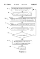
- FIG. 8 flowchart depicts a method of operating the imaging apparatus depicted in FIGS. 6-7, using a fixed sampling rate.
- the signals produced by each of sensors 42, 44 at fixed time sampling intervals having times of occurrence t 1 , t 2 , . . . t n are received as indicated at step 50 (i.e. sensors 42, 44 are scanned to obtain two 1 ⁇ n pixel images of the two segments of object 12 which are respectively currently adjacent viewing regions 46, 48).
- the scanned image signal produced by array 42 is stored in buffer 24, together with a signal representative of that signal's time of occurrence, as indicated at step 52.
- a selected plurality of the previously scanned signals stored in buffer 24 are compared with the scanned image signal produced by array 44 to find the stored signal which best matches (i.e. which is most similar to) the scanned image signal produced by array 44.
- the speed S of object 12 is then determined, at step 56, as d/(t j -t m ), where t j is the time of occurrence of a selected one of the scanned image signals produced by array 44, and t m is the time of occurrence of the stored signal which best matches the selected array 44 signal.
- step 58 the speed information is stored in buffer 24 by appending the speed information to or otherwise associating it with the stored signal which best matches the scanned image signal produced by array 44.
- step 60 the aforementioned steps are repeated, commencing with step 50, until the scanning process is finished. Because arrays 42, 44 are spaced as aforesaid, steps 50, 52 are typically repeated a plurality of times for different segments as object 12 moves over viewing region 46 before reaching viewing region 48.
- FIG. 9 flowchart depicts an alternative method of operating the FIGS. 6-7 imaging apparatus, using real-time scan rate control.
- Steps 70, 72, 74 and 76 are identical to FIG. 8 steps 50, 52, 54 and 56 respectively, except that whereas the FIG. 8 method used a fixed sampling rate, the FIG. 9 method uses a variable sampling rate which is determined by the (variable) speed S of object 12 and the desired (fixed) resolution R of the final image.
- FIG. 9 method normalizes the scan rate as a function of speed, the composite image can be read directly from buffer 24 at step 82 as soon as the scanning process is complete, whereas the FIG. 8 method requires normalization of the width of each image strip, as previously explained. It can thus be seen that the FIG. 9 method produces the final image more quickly than the FIG. 8 method. However, the FIG. 9 method is more complex than the FIG. 8 method. For example, a faster, more expensive version of processor 22 may be required to reliably implement the FIG. 9 method.
- FIG. 10 depicts a sensor having first, second and third parallel linear arrays 84, 86, 88.
- First and second arrays 84, 86 are spaced apart by a distance d 12 ;
- second and third arrays 86, 88 are spaced apart by a distance d 23 ;
- Arrays 84, 86 and 88 may each be 1 ⁇ n pixel linear arrays, and they may be employed in an imaging apparatus like that depicted in FIG.
- arrays 84, 86 and 88 each "see" different segments of object 12. More particularly, array 86 sees a segment of object 12 which is spaced a distance d 12 ahead of the segment seen by array 84; and, array 88 sees a segment of object 12 which is spaced a distance d 23 ahead of the segment seen by array 86 and which is also spaced a distance d 13 ahead of the segment seen by array 84.
- the FIG. 11 flowchart depicts a method of operating an imaging apparatus incorporating the FIG. 10 triple linear array sensor, using a fixed sampling rate.
- the FIG. 11 method is identical to the FIG. 8 method, except that whereas the FIG. 8 method is adapted to operation of the FIG. 5 dual linear array sensor, the FIG. 11 method is adapted to operation of the FIG. 10 triple linear array sensor.
- the signals produced by each of sensors 84, 86, 88 at fixed time sampling intervals having times of occurrence t 1 , t 2 , . . . t n are received as three 1 ⁇ n pixel images of the three segments of object 12 seen by the three sensors at the respective sample times.
- the scanned image signal produced by the first array 84 is stored in buffer 24, together with a signal representative of that signal's time of occurrence, as indicated at step 92.
- the previously scanned signals stored in buffer 24 are compared with the scanned image signals produced by both second array 86 and third array 88 to find the stored signal most similar to (i.e. which best matches) the scanned image signal produced by first array 84.
- the speed S of object 12 is then determined, at step 96, as an appropriately weighted function of d 12 /(t j -t m ), d 23 /(t m -t o ), and d 13 /(t k -t o ) [i.e.
- the speed information is stored in buffer 24 by appending the speed information to or otherwise associating it with the stored signal which best matches the scanned image signal produced by array 84.
- the aforementioned steps are repeated, commencing with step 90, until the scanning process is finished.
- the composite image is formed, at steps 102-104, by sequentially extracting image "strips" of equal width from the scanned image signals stored in buffer 24, as discussed above in relation to step 62 of FIG. 8.
- FIG. 12 depicts a sensor having four parallel linear arrays 106, 108, 110 and 112.
- Array 106 is covered by a red band-pass filter and accordingly "sees” only the red portion of the colour spectrum.
- arrays 108, 110 are covered by green and blue band-pass filters respectively and thus "see” only green and blue portions of the colour spectrum respectively.
- Array 112 has no filter (or may have a transparent cover) and accordingly "sees” the full colour spectrum.
- Arrays 106, 108 are spaced apart by a distance "d”.
- Arrays 108, 110 and 110, 112 may be similarly spaced, although as noted above it is not essential that the array spacing be equal in any embodiment of the invention.
- FIG. 13 imaging apparatus incorporating arrays 106, 108, 110, 112 is similar to that described above in relation to FIG. 6 except that four spaced, parallel viewing regions 114, 116, 118, 119 are provided in cover plate 18.
- sensor arrays 106, 108, 110, 112 are hereafter respectively designated “R” (red), “G” (green), “B” (blue) and “C” (clear), as indicated in FIGS. 12-14.
- the FIG. 14 flowchart depicts a method of operating the FIG. 13 colour imaging apparatus, using a fixed sampling rate.
- the FIG. 14 method is identical to the FIGS. 8 and 11 methods, except that whereas the FIGS. 8 and 11 methods are respectively adapted to the operation of dual and triple linear array sensors, the FIG. 14 method is adapted to operation of the FIG. 12 quadruple linear array colour sensor.
- the signals produced by each of the R, G, B and C sensors at fixed time sampling intervals having times of occurrence t 1 , t 2 , . . . t n are received as four 1 ⁇ n pixel images of the four segments of object 12 seen by the four sensors at the respective sample times.
- the scanned R image signal produced by the R sensor is stored in an "R” buffer
- the scanned G image signal produced by the G sensor is stored in a “G” buffer
- the scanned B image signal produced by the B sensor is stored in a "B” buffer.
- a signal representative of the stored R, G or B image signal's time of occurrence is also stored in the respective R, G and B buffers, as indicated at step 122.
- the previously scanned signals stored in the R, G and B buffers are compared with the scanned image signal produced by the C sensor to find the stored R signal most similar to (i.e.
- the speed S of object 12 is then determined, at step 126, as an appropriately weighted function of 3d/(t 1 -t R ), 2d(t 1 -t G ) and d/(t 1 -t B ), where t 1 is the time of occurrence of a selected one of the C image signals, and t R , t G and t B are respectively the times of occurrence of the stored R, G and B signals which best match the selected C image signal.
- the speed information is stored in the R, G and B buffers respectively, by appending the speed information to or otherwise associating it with the stored R, G and B signals which best match the scanned C image signal.
- the aforementioned steps are repeated, commencing with step 120, until the scanning process is finished.
- the R, G and B components of the image are formed, at steps 132-134, by sequentially extracting image "strips" of equal width from the scanned image signals stored in the R, G and B buffers respectively.
- the R, G and B image components are then merged in well known fashion to yield the final, composite image.
- FIGS. 10 and 12 sensors have been described with reference to a fixed sampling rate, those skilled in the art will appreciate that either sensor could alternatively be operated using real-time scan rate control, as described above with reference to FIG. 9 for the dual array sensor of FIG. 5.
- non-optical sensors such as capacitive linear arrays may be used as the linear sensor arrays referred to herein.
- the colour imaging apparatus of FIGS. 12-13 has been described as having four sensors, those skilled in the art will understand that the "C" sensor may be eliminated if it can be assumed that the object being imaged is sufficiently multi-spectral in colour to facilitate adequate correlation between the R, G and B sensors without a base reference.
- any of the aforementioned 1 ⁇ n pixel linear arrays an m ⁇ n pixel "area" array, where m ⁇ 2 (i.e. m rows, each having n pixels).
- m ⁇ 2 i.e. m rows, each having n pixels.
- any desired combination of rows of such an area array could be scanned as hereinbefore described in the context of discrete linear arrays.
- the scope of the invention is to be construed in accordance with the substance defined by the following claims.
Abstract
Description
Claims (5)
Priority Applications (10)
| Application Number | Priority Date | Filing Date | Title |
|---|---|---|---|
| US08/892,577 US6002815A (en) | 1997-07-16 | 1997-07-16 | Linear sensor imaging method and apparatus |
| EP98933415A EP1020069A2 (en) | 1997-07-16 | 1998-07-15 | Linear sensor imaging method and apparatus |
| PCT/CA1998/000690 WO1999004550A2 (en) | 1997-07-16 | 1998-07-15 | Linear sensor imaging method and apparatus |
| KR10-2000-7000466A KR100429081B1 (en) | 1997-07-16 | 1998-07-15 | Linear sensor imaging method and apparatus |
| AU83296/98A AU8329698A (en) | 1997-07-16 | 1998-07-15 | Linear sensor imaging method and apparatus |
| CA002294004A CA2294004C (en) | 1997-07-16 | 1998-07-15 | Linear sensor imaging method and apparatus |
| CNB988072602A CN1174604C (en) | 1997-07-16 | 1998-07-15 | Linear sensor imaging method and apparatus |
| JP50602499A JP3989560B2 (en) | 1997-07-16 | 1998-07-15 | Linear sensor imaging method and apparatus |
| IL13406798A IL134067A0 (en) | 1997-07-16 | 1998-07-15 | Linear sensor imaging method and apparatus |
| TW087116285A TW399388B (en) | 1997-07-16 | 1998-09-30 | Linear sensor imaging method and apparatus |
Applications Claiming Priority (1)
| Application Number | Priority Date | Filing Date | Title |
|---|---|---|---|
| US08/892,577 US6002815A (en) | 1997-07-16 | 1997-07-16 | Linear sensor imaging method and apparatus |
Publications (1)
| Publication Number | Publication Date |
|---|---|
| US6002815A true US6002815A (en) | 1999-12-14 |
Family
ID=25400164
Family Applications (1)
| Application Number | Title | Priority Date | Filing Date |
|---|---|---|---|
| US08/892,577 Expired - Lifetime US6002815A (en) | 1997-07-16 | 1997-07-16 | Linear sensor imaging method and apparatus |
Country Status (10)
| Country | Link |
|---|---|
| US (1) | US6002815A (en) |
| EP (1) | EP1020069A2 (en) |
| JP (1) | JP3989560B2 (en) |
| KR (1) | KR100429081B1 (en) |
| CN (1) | CN1174604C (en) |
| AU (1) | AU8329698A (en) |
| CA (1) | CA2294004C (en) |
| IL (1) | IL134067A0 (en) |
| TW (1) | TW399388B (en) |
| WO (1) | WO1999004550A2 (en) |
Cited By (69)
| Publication number | Priority date | Publication date | Assignee | Title |
|---|---|---|---|---|
| US6333989B1 (en) | 1999-03-29 | 2001-12-25 | Dew Engineering And Development Limited | Contact imaging device |
| US20030002719A1 (en) * | 2001-06-27 | 2003-01-02 | Laurence Hamid | Swipe imager with multiple sensing arrays |
| US20030169229A1 (en) * | 2000-06-09 | 2003-09-11 | Stig Mathiassen | Pointer tool |
| US20040041914A1 (en) * | 2002-08-28 | 2004-03-04 | Peters Leo J. | Retinal array compound camera system |
| US20040081339A1 (en) * | 2000-12-05 | 2004-04-29 | Benkley Fred G. | Swiped aperture capacitive fingerprint sensing systems and methods |
| US20050116045A1 (en) * | 2003-12-01 | 2005-06-02 | Tso-Chia Chang | Handheld device with tract input function |
| US20050244038A1 (en) * | 2004-04-16 | 2005-11-03 | Validity Sensors, Inc. | Finger position sensing methods and apparatus |
| US20060083411A1 (en) * | 2004-10-04 | 2006-04-20 | Validity Sensors, Inc. | Fingerprint sensing assemblies and methods of making |
| US20060088195A1 (en) * | 2004-10-13 | 2006-04-27 | Authentec, Inc. | Finger sensing device for navigation and related methods |
| US20060182319A1 (en) * | 2005-02-17 | 2006-08-17 | Authentec, Inc. | Finger sensor apparatus using image resampling and associated methods |
| US20070031011A1 (en) * | 2005-07-19 | 2007-02-08 | Validity Sensors, Inc. | Electronic fingerprint sensor with differential noise cancellation |
| US20070112525A1 (en) * | 2005-11-16 | 2007-05-17 | Songtao Li | System and device for image-based biological data quantification |
| US7289649B1 (en) * | 2000-08-10 | 2007-10-30 | Avago Technologies Ecbu Ip (Singapore) Pte. Ltd. | Fingerprint imager |
| WO2008033265A2 (en) * | 2006-09-11 | 2008-03-20 | Validity Sensors, Inc. | Method and apparatus for fingerprint motion tracking using an in-line array |
| US20080304723A1 (en) * | 2007-06-11 | 2008-12-11 | Ming Hsieh | Bio-reader device with ticket identification |
| US20080317290A1 (en) * | 2007-06-19 | 2008-12-25 | Mitsumi Electric Co., Ltd. | Fingerprint image forming apparatus, finger movement amount calculation method, and fingerprint image forming method |
| US20100006742A1 (en) * | 2005-11-16 | 2010-01-14 | Accu-Sort Systems, Inc. | Large depth of field line scan camera |
| US20100027852A1 (en) * | 2004-11-12 | 2010-02-04 | Ming Hsieh | System and Method for Fast Biometric Pattern Matching |
| US8005276B2 (en) | 2008-04-04 | 2011-08-23 | Validity Sensors, Inc. | Apparatus and method for reducing parasitic capacitive coupling and noise in fingerprint sensing circuits |
| US8077935B2 (en) | 2004-04-23 | 2011-12-13 | Validity Sensors, Inc. | Methods and apparatus for acquiring a swiped fingerprint image |
| US8107212B2 (en) | 2007-04-30 | 2012-01-31 | Validity Sensors, Inc. | Apparatus and method for protecting fingerprint sensing circuitry from electrostatic discharge |
| US8116540B2 (en) | 2008-04-04 | 2012-02-14 | Validity Sensors, Inc. | Apparatus and method for reducing noise in fingerprint sensing circuits |
| US8131026B2 (en) | 2004-04-16 | 2012-03-06 | Validity Sensors, Inc. | Method and apparatus for fingerprint image reconstruction |
| US8165355B2 (en) | 2006-09-11 | 2012-04-24 | Validity Sensors, Inc. | Method and apparatus for fingerprint motion tracking using an in-line array for use in navigation applications |
| US8175345B2 (en) | 2004-04-16 | 2012-05-08 | Validity Sensors, Inc. | Unitized ergonomic two-dimensional fingerprint motion tracking device and method |
| US8204281B2 (en) | 2007-12-14 | 2012-06-19 | Validity Sensors, Inc. | System and method to remove artifacts from fingerprint sensor scans |
| US8229184B2 (en) | 2004-04-16 | 2012-07-24 | Validity Sensors, Inc. | Method and algorithm for accurate finger motion tracking |
| DE102011122680A1 (en) | 2011-01-26 | 2012-07-26 | Validity Sensors, Inc. | User input using a dual line scanning device, method and computer program product |
| DE102011122681A1 (en) | 2011-01-26 | 2012-08-02 | Validity Sensors, Inc. | System and method for image reconstruction with dual-line scanner using line counts |
| US8254728B2 (en) | 2002-02-14 | 2012-08-28 | 3M Cogent, Inc. | Method and apparatus for two dimensional image processing |
| US20120218231A1 (en) * | 2011-02-28 | 2012-08-30 | Motorola Mobility, Inc. | Electronic Device and Method for Calibration of a Touch Screen |
| US8275179B2 (en) | 2007-05-01 | 2012-09-25 | 3M Cogent, Inc. | Apparatus for capturing a high quality image of a moist finger |
| US8278946B2 (en) | 2009-01-15 | 2012-10-02 | Validity Sensors, Inc. | Apparatus and method for detecting finger activity on a fingerprint sensor |
| US8276816B2 (en) | 2007-12-14 | 2012-10-02 | Validity Sensors, Inc. | Smart card system with ergonomic fingerprint sensor and method of using |
| US8290150B2 (en) | 2007-05-11 | 2012-10-16 | Validity Sensors, Inc. | Method and system for electronically securing an electronic device using physically unclonable functions |
| US8331096B2 (en) | 2010-08-20 | 2012-12-11 | Validity Sensors, Inc. | Fingerprint acquisition expansion card apparatus |
| US8358815B2 (en) | 2004-04-16 | 2013-01-22 | Validity Sensors, Inc. | Method and apparatus for two-dimensional finger motion tracking and control |
| US8374407B2 (en) | 2009-01-28 | 2013-02-12 | Validity Sensors, Inc. | Live finger detection |
| US8391568B2 (en) | 2008-11-10 | 2013-03-05 | Validity Sensors, Inc. | System and method for improved scanning of fingerprint edges |
| US8421890B2 (en) | 2010-01-15 | 2013-04-16 | Picofield Technologies, Inc. | Electronic imager using an impedance sensor grid array and method of making |
| US20130094715A1 (en) * | 2006-09-11 | 2013-04-18 | Validity Sensors, Inc. | System for determining the motion of a fingerprint surface with respect to a sensor surface |
| US8483960B2 (en) | 2002-09-20 | 2013-07-09 | Visual Intelligence, LP | Self-calibrated, remote imaging and data processing system |
| US8600122B2 (en) | 2009-01-15 | 2013-12-03 | Validity Sensors, Inc. | Apparatus and method for culling substantially redundant data in fingerprint sensing circuits |
| US8698594B2 (en) | 2008-07-22 | 2014-04-15 | Synaptics Incorporated | System, device and method for securing a user device component by authenticating the user of a biometric sensor by performance of a replication of a portion of an authentication process performed at a remote computing device |
| US8716613B2 (en) | 2010-03-02 | 2014-05-06 | Synaptics Incoporated | Apparatus and method for electrostatic discharge protection |
| US8791792B2 (en) | 2010-01-15 | 2014-07-29 | Idex Asa | Electronic imager using an impedance sensor grid array mounted on or about a switch and method of making |
| US20140286546A1 (en) * | 2013-03-22 | 2014-09-25 | Suprema Inc. | Apparatus and method for processing fingerprint image |
| US8866347B2 (en) | 2010-01-15 | 2014-10-21 | Idex Asa | Biometric image sensing |
| US9001040B2 (en) | 2010-06-02 | 2015-04-07 | Synaptics Incorporated | Integrated fingerprint sensor and navigation device |
| US9137438B2 (en) | 2012-03-27 | 2015-09-15 | Synaptics Incorporated | Biometric object sensor and method |
| US9152838B2 (en) | 2012-03-29 | 2015-10-06 | Synaptics Incorporated | Fingerprint sensor packagings and methods |
| US9195877B2 (en) | 2011-12-23 | 2015-11-24 | Synaptics Incorporated | Methods and devices for capacitive image sensing |
| WO2015181610A1 (en) | 2014-05-27 | 2015-12-03 | Idex Asa | Multi-lined sensor |
| US20150347810A1 (en) * | 2014-05-30 | 2015-12-03 | Apple Inc. | Electronic device for reallocating finger biometric template nodes in a set memory space and related methods |
| US9251329B2 (en) | 2012-03-27 | 2016-02-02 | Synaptics Incorporated | Button depress wakeup and wakeup strategy |
| US9268991B2 (en) | 2012-03-27 | 2016-02-23 | Synaptics Incorporated | Method of and system for enrolling and matching biometric data |
| US9274553B2 (en) | 2009-10-30 | 2016-03-01 | Synaptics Incorporated | Fingerprint sensor and integratable electronic display |
| US9336428B2 (en) | 2009-10-30 | 2016-05-10 | Synaptics Incorporated | Integrated fingerprint sensor and display |
| US9400911B2 (en) | 2009-10-30 | 2016-07-26 | Synaptics Incorporated | Fingerprint sensor and integratable electronic display |
| US9406580B2 (en) | 2011-03-16 | 2016-08-02 | Synaptics Incorporated | Packaging for fingerprint sensors and methods of manufacture |
| US9600709B2 (en) | 2012-03-28 | 2017-03-21 | Synaptics Incorporated | Methods and systems for enrolling biometric data |
| US9666635B2 (en) | 2010-02-19 | 2017-05-30 | Synaptics Incorporated | Fingerprint sensing circuit |
| US9665762B2 (en) | 2013-01-11 | 2017-05-30 | Synaptics Incorporated | Tiered wakeup strategy |
| USD791772S1 (en) * | 2015-05-20 | 2017-07-11 | Chaya Coleena Hendrick | Smart card with a fingerprint sensor |
| US9785299B2 (en) | 2012-01-03 | 2017-10-10 | Synaptics Incorporated | Structures and manufacturing methods for glass covered electronic devices |
| US9798917B2 (en) | 2012-04-10 | 2017-10-24 | Idex Asa | Biometric sensing |
| US10043052B2 (en) | 2011-10-27 | 2018-08-07 | Synaptics Incorporated | Electronic device packages and methods |
| US10630220B2 (en) * | 2011-11-16 | 2020-04-21 | Rockwell Automation, Inc. | Controlled motion system |
| USRE49105E1 (en) | 2002-09-20 | 2022-06-14 | Vi Technologies, Llc | Self-calibrated, remote imaging and data processing system |
Families Citing this family (5)
| Publication number | Priority date | Publication date | Assignee | Title |
|---|---|---|---|---|
| AU2002328437A1 (en) | 2002-09-17 | 2004-04-08 | Fujitsu Limited | Biological information acquiring apparatus and authentication apparatus using biological information |
| TWI568237B (en) * | 2015-07-29 | 2017-01-21 | 東友科技股份有限公司 | Image capture method and image capture and synthesis method |
| US11262316B2 (en) | 2017-10-02 | 2022-03-01 | Teledyne Digital Imaging, Inc. | Method of synchronizing a line scan camera |
| WO2020062269A1 (en) * | 2018-09-30 | 2020-04-02 | 深圳配天智能技术研究院有限公司 | Image sensor, method for acquiring image, visual system and storage medium |
| CN109873915A (en) * | 2019-01-16 | 2019-06-11 | 北京五岳鑫信息技术股份有限公司 | A kind of compensation device and method of scanner |
Citations (4)
| Publication number | Priority date | Publication date | Assignee | Title |
|---|---|---|---|---|
| US4833724A (en) * | 1986-08-14 | 1989-05-23 | Amada Engineering & Service Co., Inc. | Imaging device |
| US5613014A (en) * | 1994-10-12 | 1997-03-18 | Martin Marietta Corp. | Fingerprint matching system |
| US5633947A (en) * | 1991-03-21 | 1997-05-27 | Thorn Emi Plc | Method and apparatus for fingerprint characterization and recognition using auto correlation pattern |
| US5828773A (en) * | 1996-01-26 | 1998-10-27 | Harris Corporation | Fingerprint sensing method with finger position indication |
Family Cites Families (4)
| Publication number | Priority date | Publication date | Assignee | Title |
|---|---|---|---|---|
| JPH07111561A (en) * | 1993-10-12 | 1995-04-25 | Matsushita Electric Ind Co Ltd | Original reading device |
| JP3120354B2 (en) * | 1995-01-13 | 2000-12-25 | セイコーエプソン株式会社 | Image processing method and image processing apparatus |
| US5719970A (en) * | 1994-07-08 | 1998-02-17 | Seiko Epson Corporation | Image processing method and device |
| US5578813A (en) * | 1995-03-02 | 1996-11-26 | Allen; Ross R. | Freehand image scanning device which compensates for non-linear movement |
-
1997
- 1997-07-16 US US08/892,577 patent/US6002815A/en not_active Expired - Lifetime
-
1998
- 1998-07-15 AU AU83296/98A patent/AU8329698A/en not_active Abandoned
- 1998-07-15 IL IL13406798A patent/IL134067A0/en unknown
- 1998-07-15 WO PCT/CA1998/000690 patent/WO1999004550A2/en not_active Application Discontinuation
- 1998-07-15 CN CNB988072602A patent/CN1174604C/en not_active Expired - Fee Related
- 1998-07-15 KR KR10-2000-7000466A patent/KR100429081B1/en not_active IP Right Cessation
- 1998-07-15 CA CA002294004A patent/CA2294004C/en not_active Expired - Lifetime
- 1998-07-15 EP EP98933415A patent/EP1020069A2/en not_active Withdrawn
- 1998-07-15 JP JP50602499A patent/JP3989560B2/en not_active Expired - Lifetime
- 1998-09-30 TW TW087116285A patent/TW399388B/en not_active IP Right Cessation
Patent Citations (4)
| Publication number | Priority date | Publication date | Assignee | Title |
|---|---|---|---|---|
| US4833724A (en) * | 1986-08-14 | 1989-05-23 | Amada Engineering & Service Co., Inc. | Imaging device |
| US5633947A (en) * | 1991-03-21 | 1997-05-27 | Thorn Emi Plc | Method and apparatus for fingerprint characterization and recognition using auto correlation pattern |
| US5613014A (en) * | 1994-10-12 | 1997-03-18 | Martin Marietta Corp. | Fingerprint matching system |
| US5828773A (en) * | 1996-01-26 | 1998-10-27 | Harris Corporation | Fingerprint sensing method with finger position indication |
Cited By (133)
| Publication number | Priority date | Publication date | Assignee | Title |
|---|---|---|---|---|
| US6333989B1 (en) | 1999-03-29 | 2001-12-25 | Dew Engineering And Development Limited | Contact imaging device |
| US7308121B2 (en) * | 2000-06-09 | 2007-12-11 | Idex Asa | Pointer tool |
| US20030169229A1 (en) * | 2000-06-09 | 2003-09-11 | Stig Mathiassen | Pointer tool |
| US20080129702A1 (en) * | 2000-06-09 | 2008-06-05 | Idex Asa | Pointer Tool |
| US8005275B2 (en) | 2000-06-09 | 2011-08-23 | Idex Asa | Pointer tool |
| US7289649B1 (en) * | 2000-08-10 | 2007-10-30 | Avago Technologies Ecbu Ip (Singapore) Pte. Ltd. | Fingerprint imager |
| US20040081339A1 (en) * | 2000-12-05 | 2004-04-29 | Benkley Fred G. | Swiped aperture capacitive fingerprint sensing systems and methods |
| US7146024B2 (en) | 2000-12-05 | 2006-12-05 | Validity Sensors, Inc. | Swiped aperture capacitive fingerprint sensing systems and methods |
| US7099496B2 (en) | 2000-12-05 | 2006-08-29 | Validity Sensors, Inc. | Swiped aperture capacitive fingerprint sensing systems and methods |
| US7369684B2 (en) | 2001-06-27 | 2008-05-06 | Activcard Ireland Limited | Swipe imager with multiple sensing arrays |
| US20070154073A1 (en) * | 2001-06-27 | 2007-07-05 | Activcard Ireland Limited | Swipe imager with multiple sensing arrays |
| US7043061B2 (en) * | 2001-06-27 | 2006-05-09 | Laurence Hamid | Swipe imager with multiple sensing arrays |
| US20030002719A1 (en) * | 2001-06-27 | 2003-01-02 | Laurence Hamid | Swipe imager with multiple sensing arrays |
| US8254728B2 (en) | 2002-02-14 | 2012-08-28 | 3M Cogent, Inc. | Method and apparatus for two dimensional image processing |
| US8471907B2 (en) | 2002-08-28 | 2013-06-25 | Visual Intelligence, LP | Method of producing a remote imaging array |
| US8334903B2 (en) | 2002-08-28 | 2012-12-18 | Visual Intelligence, L.P. | Retinal array compound camera system having at least three imaging sensors |
| US7893957B2 (en) * | 2002-08-28 | 2011-02-22 | Visual Intelligence, LP | Retinal array compound camera system |
| US8896695B2 (en) | 2002-08-28 | 2014-11-25 | Visual Intelligence Lp | Retinal concave array compound camera system |
| US20040041914A1 (en) * | 2002-08-28 | 2004-03-04 | Peters Leo J. | Retinal array compound camera system |
| US20080291280A1 (en) * | 2002-08-28 | 2008-11-27 | Peters Iii Leo J | Retinal array compound camera system having at least three imaging sensors |
| US20090322883A1 (en) * | 2002-08-28 | 2009-12-31 | Visual Intelligence Systems, Inc. | Method of producing a remote imaging array |
| US8483960B2 (en) | 2002-09-20 | 2013-07-09 | Visual Intelligence, LP | Self-calibrated, remote imaging and data processing system |
| USRE49105E1 (en) | 2002-09-20 | 2022-06-14 | Vi Technologies, Llc | Self-calibrated, remote imaging and data processing system |
| US9389298B2 (en) | 2002-09-20 | 2016-07-12 | Visual Intelligence Lp | Self-calibrated, remote imaging and data processing system |
| US9797980B2 (en) | 2002-09-20 | 2017-10-24 | Visual Intelligence Lp | Self-calibrated, remote imaging and data processing system |
| US6991162B2 (en) * | 2003-12-01 | 2006-01-31 | Benq Corporation | Handheld device with tract input function |
| US20050116045A1 (en) * | 2003-12-01 | 2005-06-02 | Tso-Chia Chang | Handheld device with tract input function |
| US8358815B2 (en) | 2004-04-16 | 2013-01-22 | Validity Sensors, Inc. | Method and apparatus for two-dimensional finger motion tracking and control |
| US8131026B2 (en) | 2004-04-16 | 2012-03-06 | Validity Sensors, Inc. | Method and apparatus for fingerprint image reconstruction |
| US7463756B2 (en) | 2004-04-16 | 2008-12-09 | Validity Sensors, Inc. | Finger position sensing methods and apparatus |
| US9721137B2 (en) | 2004-04-16 | 2017-08-01 | Synaptics Incorporated | Method and apparatus for fingerprint image reconstruction |
| US20050244038A1 (en) * | 2004-04-16 | 2005-11-03 | Validity Sensors, Inc. | Finger position sensing methods and apparatus |
| US8229184B2 (en) | 2004-04-16 | 2012-07-24 | Validity Sensors, Inc. | Method and algorithm for accurate finger motion tracking |
| US8811688B2 (en) | 2004-04-16 | 2014-08-19 | Synaptics Incorporated | Method and apparatus for fingerprint image reconstruction |
| US8175345B2 (en) | 2004-04-16 | 2012-05-08 | Validity Sensors, Inc. | Unitized ergonomic two-dimensional fingerprint motion tracking device and method |
| US8315444B2 (en) | 2004-04-16 | 2012-11-20 | Validity Sensors, Inc. | Unitized ergonomic two-dimensional fingerprint motion tracking device and method |
| US8077935B2 (en) | 2004-04-23 | 2011-12-13 | Validity Sensors, Inc. | Methods and apparatus for acquiring a swiped fingerprint image |
| US7751601B2 (en) | 2004-10-04 | 2010-07-06 | Validity Sensors, Inc. | Fingerprint sensing assemblies and methods of making |
| US8224044B2 (en) * | 2004-10-04 | 2012-07-17 | Validity Sensors, Inc. | Fingerprint sensing assemblies and methods of making |
| US20060083411A1 (en) * | 2004-10-04 | 2006-04-20 | Validity Sensors, Inc. | Fingerprint sensing assemblies and methods of making |
| US8867799B2 (en) | 2004-10-04 | 2014-10-21 | Synaptics Incorporated | Fingerprint sensing assemblies and methods of making |
| US7693314B2 (en) | 2004-10-13 | 2010-04-06 | Authentec, Inc. | Finger sensing device for navigation and related methods |
| US20060088195A1 (en) * | 2004-10-13 | 2006-04-27 | Authentec, Inc. | Finger sensing device for navigation and related methods |
| US20060093191A1 (en) * | 2004-10-13 | 2006-05-04 | Authentec, Inc. | Finger sensor with data throttling and associated methods |
| US7689012B2 (en) | 2004-10-13 | 2010-03-30 | Authentec, Inc. | Finger sensor with data throttling and associated methods |
| US20100027852A1 (en) * | 2004-11-12 | 2010-02-04 | Ming Hsieh | System and Method for Fast Biometric Pattern Matching |
| US8379982B2 (en) | 2004-11-12 | 2013-02-19 | 3M Cogent, Inc. | System and method for fast biometric pattern matching |
| US20060182319A1 (en) * | 2005-02-17 | 2006-08-17 | Authentec, Inc. | Finger sensor apparatus using image resampling and associated methods |
| US7734074B2 (en) | 2005-02-17 | 2010-06-08 | Authentec, Inc. | Finger sensor apparatus using image resampling and associated methods |
| US20070031011A1 (en) * | 2005-07-19 | 2007-02-08 | Validity Sensors, Inc. | Electronic fingerprint sensor with differential noise cancellation |
| US7460697B2 (en) | 2005-07-19 | 2008-12-02 | Validity Sensors, Inc. | Electronic fingerprint sensor with differential noise cancellation |
| US20100006742A1 (en) * | 2005-11-16 | 2010-01-14 | Accu-Sort Systems, Inc. | Large depth of field line scan camera |
| US8110790B2 (en) | 2005-11-16 | 2012-02-07 | Accu-Sort Systems, Inc. | Large depth of field line scan camera |
| US8583379B2 (en) | 2005-11-16 | 2013-11-12 | 3M Innovative Properties Company | Method and device for image-based biological data quantification |
| US20070112525A1 (en) * | 2005-11-16 | 2007-05-17 | Songtao Li | System and device for image-based biological data quantification |
| US8131477B2 (en) | 2005-11-16 | 2012-03-06 | 3M Cogent, Inc. | Method and device for image-based biological data quantification |
| US20130094715A1 (en) * | 2006-09-11 | 2013-04-18 | Validity Sensors, Inc. | System for determining the motion of a fingerprint surface with respect to a sensor surface |
| WO2008033265A3 (en) * | 2006-09-11 | 2008-06-12 | Validity Sensors Inc | Method and apparatus for fingerprint motion tracking using an in-line array |
| WO2008033265A2 (en) * | 2006-09-11 | 2008-03-20 | Validity Sensors, Inc. | Method and apparatus for fingerprint motion tracking using an in-line array |
| US8693736B2 (en) * | 2006-09-11 | 2014-04-08 | Synaptics Incorporated | System for determining the motion of a fingerprint surface with respect to a sensor surface |
| US8165355B2 (en) | 2006-09-11 | 2012-04-24 | Validity Sensors, Inc. | Method and apparatus for fingerprint motion tracking using an in-line array for use in navigation applications |
| US8447077B2 (en) | 2006-09-11 | 2013-05-21 | Validity Sensors, Inc. | Method and apparatus for fingerprint motion tracking using an in-line array |
| US8107212B2 (en) | 2007-04-30 | 2012-01-31 | Validity Sensors, Inc. | Apparatus and method for protecting fingerprint sensing circuitry from electrostatic discharge |
| US8275179B2 (en) | 2007-05-01 | 2012-09-25 | 3M Cogent, Inc. | Apparatus for capturing a high quality image of a moist finger |
| US8290150B2 (en) | 2007-05-11 | 2012-10-16 | Validity Sensors, Inc. | Method and system for electronically securing an electronic device using physically unclonable functions |
| US8411916B2 (en) | 2007-06-11 | 2013-04-02 | 3M Cogent, Inc. | Bio-reader device with ticket identification |
| US20080304723A1 (en) * | 2007-06-11 | 2008-12-11 | Ming Hsieh | Bio-reader device with ticket identification |
| US8059872B2 (en) * | 2007-06-19 | 2011-11-15 | Mitsumi Electric Co., Ltd. | Fingerprint image forming apparatus, finger movement amount calculation method, and fingerprint image forming method |
| US20080317290A1 (en) * | 2007-06-19 | 2008-12-25 | Mitsumi Electric Co., Ltd. | Fingerprint image forming apparatus, finger movement amount calculation method, and fingerprint image forming method |
| US8276816B2 (en) | 2007-12-14 | 2012-10-02 | Validity Sensors, Inc. | Smart card system with ergonomic fingerprint sensor and method of using |
| US8204281B2 (en) | 2007-12-14 | 2012-06-19 | Validity Sensors, Inc. | System and method to remove artifacts from fingerprint sensor scans |
| USRE45650E1 (en) | 2008-04-04 | 2015-08-11 | Synaptics Incorporated | Apparatus and method for reducing parasitic capacitive coupling and noise in fingerprint sensing circuits |
| US8116540B2 (en) | 2008-04-04 | 2012-02-14 | Validity Sensors, Inc. | Apparatus and method for reducing noise in fingerprint sensing circuits |
| US8005276B2 (en) | 2008-04-04 | 2011-08-23 | Validity Sensors, Inc. | Apparatus and method for reducing parasitic capacitive coupling and noise in fingerprint sensing circuits |
| US8520913B2 (en) | 2008-04-04 | 2013-08-27 | Validity Sensors, Inc. | Apparatus and method for reducing noise in fingerprint sensing circuits |
| US8787632B2 (en) | 2008-04-04 | 2014-07-22 | Synaptics Incorporated | Apparatus and method for reducing noise in fingerprint sensing circuits |
| US8698594B2 (en) | 2008-07-22 | 2014-04-15 | Synaptics Incorporated | System, device and method for securing a user device component by authenticating the user of a biometric sensor by performance of a replication of a portion of an authentication process performed at a remote computing device |
| US8391568B2 (en) | 2008-11-10 | 2013-03-05 | Validity Sensors, Inc. | System and method for improved scanning of fingerprint edges |
| US8593160B2 (en) | 2009-01-15 | 2013-11-26 | Validity Sensors, Inc. | Apparatus and method for finger activity on a fingerprint sensor |
| US8278946B2 (en) | 2009-01-15 | 2012-10-02 | Validity Sensors, Inc. | Apparatus and method for detecting finger activity on a fingerprint sensor |
| US8600122B2 (en) | 2009-01-15 | 2013-12-03 | Validity Sensors, Inc. | Apparatus and method for culling substantially redundant data in fingerprint sensing circuits |
| US8374407B2 (en) | 2009-01-28 | 2013-02-12 | Validity Sensors, Inc. | Live finger detection |
| US9274553B2 (en) | 2009-10-30 | 2016-03-01 | Synaptics Incorporated | Fingerprint sensor and integratable electronic display |
| US9336428B2 (en) | 2009-10-30 | 2016-05-10 | Synaptics Incorporated | Integrated fingerprint sensor and display |
| US9400911B2 (en) | 2009-10-30 | 2016-07-26 | Synaptics Incorporated | Fingerprint sensor and integratable electronic display |
| US8421890B2 (en) | 2010-01-15 | 2013-04-16 | Picofield Technologies, Inc. | Electronic imager using an impedance sensor grid array and method of making |
| US9268988B2 (en) | 2010-01-15 | 2016-02-23 | Idex Asa | Biometric image sensing |
| US8866347B2 (en) | 2010-01-15 | 2014-10-21 | Idex Asa | Biometric image sensing |
| US9659208B2 (en) | 2010-01-15 | 2017-05-23 | Idex Asa | Biometric image sensing |
| US10115001B2 (en) | 2010-01-15 | 2018-10-30 | Idex Asa | Biometric image sensing |
| US9600704B2 (en) | 2010-01-15 | 2017-03-21 | Idex Asa | Electronic imager using an impedance sensor grid array and method of making |
| US10592719B2 (en) | 2010-01-15 | 2020-03-17 | Idex Biometrics Asa | Biometric image sensing |
| US8791792B2 (en) | 2010-01-15 | 2014-07-29 | Idex Asa | Electronic imager using an impedance sensor grid array mounted on or about a switch and method of making |
| US11080504B2 (en) | 2010-01-15 | 2021-08-03 | Idex Biometrics Asa | Biometric image sensing |
| US9666635B2 (en) | 2010-02-19 | 2017-05-30 | Synaptics Incorporated | Fingerprint sensing circuit |
| US8716613B2 (en) | 2010-03-02 | 2014-05-06 | Synaptics Incoporated | Apparatus and method for electrostatic discharge protection |
| US9001040B2 (en) | 2010-06-02 | 2015-04-07 | Synaptics Incorporated | Integrated fingerprint sensor and navigation device |
| US8331096B2 (en) | 2010-08-20 | 2012-12-11 | Validity Sensors, Inc. | Fingerprint acquisition expansion card apparatus |
| DE102011122681B4 (en) * | 2011-01-26 | 2016-05-25 | Synaptics, Inc. | System and method for image reconstruction with dual-line scanner using line counts |
| DE102011122680A1 (en) | 2011-01-26 | 2012-07-26 | Validity Sensors, Inc. | User input using a dual line scanning device, method and computer program product |
| US8594393B2 (en) | 2011-01-26 | 2013-11-26 | Validity Sensors | System for and method of image reconstruction with dual line scanner using line counts |
| US8538097B2 (en) | 2011-01-26 | 2013-09-17 | Validity Sensors, Inc. | User input utilizing dual line scanner apparatus and method |
| US8929619B2 (en) | 2011-01-26 | 2015-01-06 | Synaptics Incorporated | System and method of image reconstruction with dual line scanner using line counts |
| US8811723B2 (en) | 2011-01-26 | 2014-08-19 | Synaptics Incorporated | User input utilizing dual line scanner apparatus and method |
| DE102011122681A1 (en) | 2011-01-26 | 2012-08-02 | Validity Sensors, Inc. | System and method for image reconstruction with dual-line scanner using line counts |
| US20120218231A1 (en) * | 2011-02-28 | 2012-08-30 | Motorola Mobility, Inc. | Electronic Device and Method for Calibration of a Touch Screen |
| US10636717B2 (en) | 2011-03-16 | 2020-04-28 | Amkor Technology, Inc. | Packaging for fingerprint sensors and methods of manufacture |
| US9406580B2 (en) | 2011-03-16 | 2016-08-02 | Synaptics Incorporated | Packaging for fingerprint sensors and methods of manufacture |
| USRE47890E1 (en) | 2011-03-16 | 2020-03-03 | Amkor Technology, Inc. | Packaging for fingerprint sensors and methods of manufacture |
| US10043052B2 (en) | 2011-10-27 | 2018-08-07 | Synaptics Incorporated | Electronic device packages and methods |
| US10630220B2 (en) * | 2011-11-16 | 2020-04-21 | Rockwell Automation, Inc. | Controlled motion system |
| US9195877B2 (en) | 2011-12-23 | 2015-11-24 | Synaptics Incorporated | Methods and devices for capacitive image sensing |
| US9785299B2 (en) | 2012-01-03 | 2017-10-10 | Synaptics Incorporated | Structures and manufacturing methods for glass covered electronic devices |
| US9697411B2 (en) | 2012-03-27 | 2017-07-04 | Synaptics Incorporated | Biometric object sensor and method |
| US9137438B2 (en) | 2012-03-27 | 2015-09-15 | Synaptics Incorporated | Biometric object sensor and method |
| US9268991B2 (en) | 2012-03-27 | 2016-02-23 | Synaptics Incorporated | Method of and system for enrolling and matching biometric data |
| US9824200B2 (en) | 2012-03-27 | 2017-11-21 | Synaptics Incorporated | Wakeup strategy using a biometric sensor |
| US9251329B2 (en) | 2012-03-27 | 2016-02-02 | Synaptics Incorporated | Button depress wakeup and wakeup strategy |
| US10346699B2 (en) | 2012-03-28 | 2019-07-09 | Synaptics Incorporated | Methods and systems for enrolling biometric data |
| US9600709B2 (en) | 2012-03-28 | 2017-03-21 | Synaptics Incorporated | Methods and systems for enrolling biometric data |
| US9152838B2 (en) | 2012-03-29 | 2015-10-06 | Synaptics Incorporated | Fingerprint sensor packagings and methods |
| US10088939B2 (en) | 2012-04-10 | 2018-10-02 | Idex Asa | Biometric sensing |
| US10101851B2 (en) | 2012-04-10 | 2018-10-16 | Idex Asa | Display with integrated touch screen and fingerprint sensor |
| US10114497B2 (en) | 2012-04-10 | 2018-10-30 | Idex Asa | Biometric sensing |
| US9798917B2 (en) | 2012-04-10 | 2017-10-24 | Idex Asa | Biometric sensing |
| US9665762B2 (en) | 2013-01-11 | 2017-05-30 | Synaptics Incorporated | Tiered wakeup strategy |
| US20140286546A1 (en) * | 2013-03-22 | 2014-09-25 | Suprema Inc. | Apparatus and method for processing fingerprint image |
| US9330325B2 (en) * | 2013-03-22 | 2016-05-03 | Suprema Inc. | Apparatus and method for reducing noise in fingerprint images |
| US9864896B2 (en) * | 2014-05-27 | 2018-01-09 | Idex Asa | Multi-lined sensor |
| WO2015181610A1 (en) | 2014-05-27 | 2015-12-03 | Idex Asa | Multi-lined sensor |
| US9292728B2 (en) * | 2014-05-30 | 2016-03-22 | Apple Inc. | Electronic device for reallocating finger biometric template nodes in a set memory space and related methods |
| US20150347810A1 (en) * | 2014-05-30 | 2015-12-03 | Apple Inc. | Electronic device for reallocating finger biometric template nodes in a set memory space and related methods |
| USD791772S1 (en) * | 2015-05-20 | 2017-07-11 | Chaya Coleena Hendrick | Smart card with a fingerprint sensor |
Also Published As
| Publication number | Publication date |
|---|---|
| EP1020069A2 (en) | 2000-07-19 |
| KR20010021902A (en) | 2001-03-15 |
| WO1999004550A3 (en) | 1999-04-22 |
| CA2294004C (en) | 2004-12-14 |
| WO1999004550A2 (en) | 1999-01-28 |
| CN1264515A (en) | 2000-08-23 |
| JP2000513539A (en) | 2000-10-10 |
| KR100429081B1 (en) | 2004-04-29 |
| IL134067A0 (en) | 2001-04-30 |
| CA2294004A1 (en) | 1999-01-28 |
| TW399388B (en) | 2000-07-21 |
| JP3989560B2 (en) | 2007-10-10 |
| CN1174604C (en) | 2004-11-03 |
| AU8329698A (en) | 1999-02-10 |
Similar Documents
| Publication | Publication Date | Title |
|---|---|---|
| US6002815A (en) | Linear sensor imaging method and apparatus | |
| US6891570B2 (en) | Method and adaptively deriving exposure time and frame rate from image motion | |
| US9942474B2 (en) | Systems and methods for performing high speed video capture and depth estimation using array cameras | |
| US5453784A (en) | Imaging apparatus and method for determining range and determining focus information | |
| US7171054B2 (en) | Scene-based method for determining focus | |
| EP0624988B1 (en) | Strobing camera system and method | |
| JP4177750B2 (en) | Imaging apparatus and method for determining important regions in archive images | |
| US20040228505A1 (en) | Image characteristic portion extraction method, computer readable medium, and data collection and processing device | |
| JPH0334713B2 (en) | ||
| US20010033677A1 (en) | Individualized fingerprint scanner | |
| KR20180030773A (en) | System and method for performing high-speed video capture and depth estimation using array cameras | |
| CN113810621A (en) | Time-sharing exposure and TDI parallel processing device and method applied to multi-line linear array camera | |
| CN112714244A (en) | Image acquisition method and system based on linear array camera | |
| KR20220105171A (en) | Camera exposure processing method and system | |
| US5805311A (en) | Color optical scanner with single linear array | |
| JP2007249950A (en) | Image acquisition device and image acquisition method | |
| CN114397016A (en) | Image cutting and splicing method and hyperspectral imaging method based on image cutting and splicing | |
| JPH11313194A (en) | Registration device and method for imaging in variable resolution | |
| EP1464029B1 (en) | Fingerprint acquisition with different types of sensors | |
| JP3548213B2 (en) | Multipoint ranging device and camera | |
| CN110533731A (en) | The scaling method of camera resolution and the caliberating device of camera resolution | |
| EP1549905B1 (en) | Height determination of the profile of a moving object using a plurality of ccd arrays | |
| JPH08279034A (en) | Image synthesizing process system and scanner | |
| JP2001067455A (en) | Device of reading number of sheets | |
| JPH09166435A (en) | Measuring method for state of road surface |
Legal Events
| Date | Code | Title | Description |
|---|---|---|---|
| AS | Assignment |
Owner name: KINETIC SCIENCES INC., CANADA Free format text: ASSIGNMENT OF ASSIGNORS INTEREST;ASSIGNORS:IMMEGA, GUY BROER;VANDERKOOY, GEOFFREY EDWARD;REEL/FRAME:008685/0516 Effective date: 19970715 |
|
| AS | Assignment |
Owner name: COGENT SYSTEMS, INC., CALIFORNIA Free format text: SECURITY INTEREST;ASSIGNOR:KINETIC SCIENCES INC.;REEL/FRAME:009823/0594 Effective date: 19990219 |
|
| FEPP | Fee payment procedure |
Free format text: PAYOR NUMBER ASSIGNED (ORIGINAL EVENT CODE: ASPN); ENTITY STATUS OF PATENT OWNER: LARGE ENTITY |
|
| STCF | Information on status: patent grant |
Free format text: PATENTED CASE |
|
| FEPP | Fee payment procedure |
Free format text: PAT HOLDER CLAIMS SMALL ENTITY STATUS, ENTITY STATUS SET TO SMALL (ORIGINAL EVENT CODE: LTOS); ENTITY STATUS OF PATENT OWNER: LARGE ENTITY |
|
| FPAY | Fee payment |
Year of fee payment: 4 |
|
| AS | Assignment |
Owner name: COGENT, INC., CALIFORNIA Free format text: PURCHASE AGREEMENT;ASSIGNOR:KINETIC SCIENCES INC.;REEL/FRAME:016369/0041 Effective date: 20050429 |
|
| CC | Certificate of correction | ||
| FPAY | Fee payment |
Year of fee payment: 8 |
|
| FEPP | Fee payment procedure |
Free format text: PAT HOLDER NO LONGER CLAIMS SMALL ENTITY STATUS, ENTITY STATUS SET TO UNDISCOUNTED (ORIGINAL EVENT CODE: STOL); ENTITY STATUS OF PATENT OWNER: LARGE ENTITY |
|
| REFU | Refund |
Free format text: REFUND - PAYMENT OF MAINTENANCE FEE, 12TH YR, SMALL ENTITY (ORIGINAL EVENT CODE: R2553); ENTITY STATUS OF PATENT OWNER: LARGE ENTITY |
|
| FPAY | Fee payment |
Year of fee payment: 12 |
|
| AS | Assignment |
Owner name: 3M COGENT, INC., CALIFORNIA Free format text: MERGER AND CHANGE OF NAME;ASSIGNOR:COGENT, INC.;REEL/FRAME:026375/0875 Effective date: 20101201 |
|
| AS | Assignment |
Owner name: GEMALTO SA, FRANCE Free format text: ASSIGNMENT OF ASSIGNORS INTEREST;ASSIGNOR:3M COGENT, INC.;REEL/FRAME:042962/0397 Effective date: 20170501 |