US5991271A - Signal-to-channel mapping for multi-channel, multi-signal transmission systems - Google Patents
Signal-to-channel mapping for multi-channel, multi-signal transmission systems Download PDFInfo
- Publication number
- US5991271A US5991271A US08/575,402 US57540295A US5991271A US 5991271 A US5991271 A US 5991271A US 57540295 A US57540295 A US 57540295A US 5991271 A US5991271 A US 5991271A
- Authority
- US
- United States
- Prior art keywords
- signal
- channel
- selecting
- pair
- types
- Prior art date
- Legal status (The legal status is an assumption and is not a legal conclusion. Google has not performed a legal analysis and makes no representation as to the accuracy of the status listed.)
- Expired - Lifetime
Links
Images


Classifications
-
- H—ELECTRICITY
- H04—ELECTRIC COMMUNICATION TECHNIQUE
- H04J—MULTIPLEX COMMUNICATION
- H04J3/00—Time-division multiplex systems
- H04J3/22—Time-division multiplex systems in which the sources have different rates or codes
-
- H—ELECTRICITY
- H04—ELECTRIC COMMUNICATION TECHNIQUE
- H04J—MULTIPLEX COMMUNICATION
- H04J3/00—Time-division multiplex systems
- H04J3/02—Details
- H04J3/14—Monitoring arrangements
Definitions
- the present invention relates to a system and method for allocating signal types to transmission channels in a multi-channel, multi-signal transmission system to improve overall system performance.
- Audio and video information originating at a service provider may be delivered to an end user via a complex switching network employing Radio Frequency (RF), fiber optic, coaxial cable (Coax), and twisted pair copper cabling which may be shielded (STP) or unshielded (UTP).
- RF Radio Frequency
- Coax coaxial cable
- UTP unshielded
- each type of cabling includes trade-offs between performance characteristics and cost which must be considered in designing and implementing such a transmission system.
- a further object of the present invention is to maximize system performance by selectively assigning particular signal types to particular channels based on a uniform decision rule.
- Another object of the present invention is to provide a system and method for optimizing overall system performance by identifying a particular signal-to-channel mapping within a given type of distribution cable which maximizes the minimum margin across all digital links transported by the cable.
- a still further object of the present invention is to provide a system and method for communication channel management which utilizes signal-to-noise ratio (SNR) to selectively assign a particular signal to a particular channel based on maximizing the minimum SNR margin across all digital links transported by a particular distribution cable.
- SNR signal-to-noise ratio
- Yet another object of the present invention is to provide a system and method for simplifying cable plant recordkeeping by utilizing a consistent decision rule across an entire cable plant region.
- a method for allocating a signal to a channel in a multi-channel, multi-signal transmission system includes selecting a channel performance criterion, selecting one of the plurality of channels for evaluation, evaluating the performance criterion for the selected channel for each of the signal types, and allocating a signal type to the selected channel based on the evaluation.
- a system is also provided for implementing the method of the present invention.
- the present invention increases system performance for a particular installed transmission system with little or no added cost because the physical transmission media need not be replaced.
- the present invention may be quickly implemented since it utilizes the currently installed cable plant. If, on the other hand, new cable plant is to be deployed, application of the present invention maximizes the capabilities of that new cable plant.
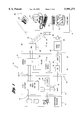
- FIG. 1 is a block diagram of a broadband transmission architecture from an information service provider to a customer utilizing curbside optical network units (ONUs);
- ONUs curbside optical network units
- FIG. 2 is a more detailed block diagram of a broadband distribution architecture from a curbside ONU to a particular associated living unit (LU);
- FIG. 3 illustrates an alternative broadband transmission architecture from an ONU to an associated LU delivering multiple signal types
- FIG. 4 illustrates filter responses for A-ATM and HSDS CAP-16 transmitters for random signal-to-channel assignment
- FIG. 7 is a diagrammatic illustration of calculation of crosstalk interference for channel management according to the present invention.
- FIG. 9 is a flow chart illustrating an alternative implementation of a method for channel management according to the present invention.
- a digital signal originating at information providers 12 may pass through a number of narrowband STM and broadband ATM switches, such as ATM Video Switch 20, which route the digital traffic to Host Digital Terminals (HDTs) 22 within each serving Central Office 24.
- a fiber optic system 26 delivers A-ATM and STM traffic to a set of remote Optical Network Units (ONUs) 28, each of which routes the correct signals to a set of 16-32 subtending Living Units (LUs) 14.
- ONUs remote Optical Network Units
- Analog signals may be captured by RF receivers at information providers 12 and transmitted to RF modulators 32 within Level 1 gateways 30 where they are converted to optical signals via laser 34.
- the optical signals are transmitted via optical fiber 40 to appropriate receivers 36 within each serving Central Office 24.
- the signals may be processed and retransmitted by laser 38 over optical fiber 40' to video nodes 42 where they are converted to electrical signals which are transmitted to splitter amplifiers 46 which distribute the signal via coax 48. These signals may be delivered directly to a living unit 14 or combined in an ONU 28 as explained in greater detail with reference to FIG. 2.
- Each ONU is capable of providing copper UTP 52 and coax drop lines 54 to a Network Interface Device (NID) 56 of an associated LU 14.
- NID Network Interface Device
- a number of devices may be connected to NID 56, such as telephones 58, computers 60, set-top terminals, i.e. "decoder boxes" 62, televisions 64, and the like.
- Such devices may be generally referred to as Customer Premise Equipment (CPE) 66.
- CPE Customer Premise Equipment
- FIG. 2 illustrates one possible transmission system architecture for distributing signals from a particular ONU 28 to its associated LUs 14 (only one of which is specifically illustrated).
- the links between an LU 14 and its associated ONU 28 include a combination of copper twisted pairs 84 and coaxial cabling 92.
- Twisted pair distribution cable 82 carries signals between ONU 28 and its subtending downstream pedestals 86 via associated twisted pairs 84.
- Allocation of particular signal types to a particular twisted pair within distributing cable 82 according to the present invention may be performed by control logic 80.
- channel management according to the present invention may be performed by a programmed microprocessor prior to a hardwired implementation which assigns particular signal types to particular channels across the entire cable plant based on the results generated by the microprocessor.
- distribution cable 82 may be an air-core (aerial) or filled (buried) cable having 28, 50, or 84 twisted pairs.
- the length of distribution cable 82 is less than or equal to 600 feet.
- Twisted pairs 84 within each distribution cable 82 are divided into sets of four, with each set dedicated to a specific LU.
- some installations allow LUs 14 which are in close proximity to an ONU 28 to be served directly by twisted pair and coaxial drop cables without the use of an intervening distribution cable 82.
- dedicated plant The concept of allocating a set of twisted pairs 84 for each LU 14, with each set to be used only for connecting to its intended LU and never any of the other LUs, is referred to as a dedicated plant.
- three of the twisted pairs 84 within distribution cable 82 are utilized for delivery of narrowband telephony services such as POTS (Plain Old Telephone Service), ISDN (Integrated Services Digital Network) basic rate, or low speed data services.
- narrowband telephony services such as POTS (Plain Old Telephone Service), ISDN (Integrated Services Digital Network) basic rate, or low speed data services.
- POTS Plain Old Telephone Service
- ISDN Integrated Services Digital Network
- a fourth twisted pair 84 within each set referred to as the A-ATM pair, carries A-ATM digital video and/or data in the downstream direction (from the service provider toward the customer), and signalling, control, and digital data in the upstream direction (from the customer toward the service provider).
- the UTP drop cable 90 has a cable length from pedestal 86 to NID 56 of less than or equal to 200 feet. Also preferably, in-home wiring within each LU 14 has a cable length of less than or equal to 100 feet.
- a given ONU 28 transmits and receives A-ATM signals to and from multiple subtending LUs simultaneously.
- the CAP-16 downstream signals on the separate A-ATM cable pairs will interfere with one another through an electromagnetic coupling mechanism known as Far End Crosstalk (FEXT).
- FEXT Far End Crosstalk
- Upstream CAP-4 signals simultaneously present on separate pairs will similarly generate and be exposed to FEXT interference.
- the signals may also introduce Near End Crosstalk (NEXT) interference to the transport system, which is even more debilitating than FEXT.
- NEXT Near End Crosstalk
- One approach to improving transmission system performance is to replace the telephony exchange distribution cable with cables having better characteristics for attenuation, NEXT, FEXT, and the like.
- Cross-talk performance may be improved by using tighter twist rates on twisted pair cabling.
- proper shielding helps to eliminate EMI.
- the present invention may be utilized separately from, or in addition to, replacing existing exchange cabling to improve overall system performance. As such, implementation of the present invention provides interim performance increases almost immediately while awaiting available resources to replace the existing cable plant.
- FIG. 3 a block diagram illustrating one possible construction of an information distribution system according to the present invention is shown.
- the system combines an improved distribution cable 82' and channel management performed by control logic 80' with an ONU 28' to improve overall system performance.
- control logic may reside within each ONU or, preferably is executed prior to installation of the cable plant (or portion thereof) so that each ONU may be hardwired based on the result of the signal-to-channel optimization.
- the system of FIG. 3 could be used to simultaneously deliver telephony, A-ATM, and HSDS services to customers.
- ONU 28' serves a total of 16 LUs, such as LU 14'. Of the 16 LUs, 12 LUs are served by a 50-pair distribution cable 82' and a collection of drop cables, indicated generally by reference numeral 116.
- distribution cable 82' has a cable length less than or equal to 600 feet while drop cables 116 have a cable length of less than or equal to 200 feet from pedestal 86' to their corresponding LUs.
- the remaining four LUs served by ONU 28' are served directly over a similar set of drop cables 108 and 110.
- the system of FIG. 3 allocates four twisted pairs for each LU such that all LUs could be simultaneously served with A-ATM, HSDS, and POTS services.
- the ONU 28' includes a set of 16 A-ATM downstream transmitter and upstream receivers 100.
- 16 downstream transmitters 102 and upstream receivers 104 may also be provided in addition to a set of 16 narrowband telephony cards 106.
- HSDS transmitters and receivers 102 and 104 may optionally process narrowband signals as well, or interface with existing narrowband cards.
- ONU 28' also includes control logic 80' which may be used implement channel management according to the present invention.
- the use of dedicated plant allocates four twisted pairs 84' within distribution cable 82' for access to a given LU, such as LU 14'.
- One of the four twisted pairs carries an A-ATM signal to pedestal 86' where the A-ATM signal is combined by VSC 88' with an analog video signal (not specifically illustrated).
- the combined signal which is frequency division multiplexed, is carried to the LU on a single coax drop cable 122.
- the second of the four twisted pairs carries narrowband telephony to pedestal 86' with a telephony drop 119 completing the connection to the NID 56'.
- the third and fourth twisted pairs carry upstream and downstream HSDS signals, respectively, to pedestal 86' and then to NID 56' via UTP drop cable 118, which preferably meets the requirements of a category 5 cable as rated by the Electronics Industry Association/Telephone Industry Association (EIA/TIA).
- EIA/TIA Electronics Industry Association/Telephone Industry Association
- the third and fourth twisted pairs can optionally simultaneously transport narrowband and HSDS signals so that an LU requesting HSDS would not be limited to a single narrowband channel. This type of simultaneous single pair narrowband and HSDS transport may be accomplished through the use of POTS splitting filters within NID 116.
- An HSDS may require a category 5 cable 114 with a cable length of less than or equal to 100 feet to connect the POTS splitter and a network port 112 of the corresponding HSDS CPE.
- FIG. 3 illustrates four different types of digital transmission links, each of which may contribute transmission impairments to the system.
- impairments include, but are not limited to, NEXT, FEXT, and Additive White Gaussian Noise (AWGN).
- NEXT NEXT
- FEXT FEXT
- AWGN Additive White Gaussian Noise
- the A-ATM downstream link from transmitter 100 operates in the 6-26 MHz band while both upstream and downstream CAP-16 HSDS links to transmitters 102 and receivers 104 operate in the 1-26 MHz region.
- the A-ATM downstream receiver within LU 14' must operate acceptably subject to the following impairments: FEXT from up to 11 A-ATM transmitters in the same distribution cable; FEXT from up to 12 HSDS downstream transmitters; NEXT from up to 12 HSDS upstream transmitters; and AWGN.
- the introduction of HSDS signals into distribution cable 82' generates new NEXT and FEXT impairments with which the A-ATM receivers 112 must contend.
- the NEXT from the upstream HSDS transmitters is of special concern because NEXT is more troublesome to the transmission than FEXT.
- the distribution cable specification describes bounds on worst-case FEXT power sum, it is useful for system simulation purposes to replace the two types of FEXT disturbers with one, while keeping the total number of interfering transmitters constant. The worst-case performance of the actual dual-source FEXT configuration will then lie between that of the two single-source FEXT cases.
- the HSDS upstream link to receiver 104 must operate in the presence of the following impairments: NEXT from up to 12 HSDS downstream transmitters; NEXT from up to 12 A-ATM downstream transmitters; FEXT from up to 11 other HSDS upstream transmitters; and AWGN. Again, the worst-case performance will lie between that of systems with 11 HSDS FEXT, AWGN, and NEXT from either 24 HSDS or 24 A-ATM downstream transmitters.
- the HSDS CAP-16 downstream link from transmitter 102 must operate in the presence of the following impairments: NEXT from the single co-located HSDS upstream transmitter; NEXT from up to 11 other HSDS upstream transmitters; FEXT from up to 11 other HSDS downstream transmitters; FEXT from up to 12 A-ATM downstream transmitters; and AWGN.
- the goal is to improve the worst-case performance of the limiting link by intelligently mapping channels, or twisted pairs within a distribution cable, to a particular signal type.
- a single decision rule based on predetermined cable characteristics is applied uniformly across all ONU installations.
- the worst-case margin for a link is the minimum margin experienced across all pairs assigned to that link type.
- FIG. 4 illustrates the response characteristics for filters used in a simulation of the transmission system of FIG. 3.
- the HSDS filter response 122 extends from about 0.5 MHz to about 26 MHz while the A-ATM filter response 120 extends from about 6 MHz to about 26 MHz.
- receiver AWGN included amplifier thermal noise at -130 dBm/Hz in addition to quantization noise introduced by an 8-bit A/D. All subtending pedestals from the ONU being simulated were assumed to be 600 feet away from that ONU.
- the pairs for consecutive sets of four LUs may be spliced at pedestals every 100-200 feet along the distribution, the level of NEXT, which is the dominant impairment in the links under study, will not be appreciably affected by that assumption.
- the LU drop cables were assumed to be approximately 200 foot in length with an additional 100 feet of wiring length within the LU.
- the LU housing the receiver under study was assumed to be 900 cable-feet away from the ONU.
- the other LU upstream transmitters were only 50 cable feet away from the downstream distribution cable end. The results were based on a CAP-16 adaptive receiver model with 32 fractionally spaced equalizer taps (T/4) and a decision feedback equalizer as illustrated and described with reference to FIG. 5.
- the decision feedback equalizer (DFE) 130 contained N taps 132, represented by d k where 1 ⁇ k ⁇ N and where N may be zero indicating that the decision feedback equalizer loop is not present.
- the complex baseband input signal s(t) may be represented by: ##EQU1## where a n 0 is the symbol sequence to be detected, a n i , 1 ⁇ i ⁇ I, are the symbol sequences carried by I synchronous interfering signals, h 0 (t) is the main channel complex equivalent baseband impulse response, and h i (t), 1 ⁇ i ⁇ I, are the interfering channel complex equivalent baseband impulse responses.
- v(t) is colored Gaussian noise with the sampled autocorrelation sequence: ##EQU2## where the symbol sequences are assumed white and of power A 2 , i.e.,
- S TX (f) is the disturbing transmitters' power spectral density
- H cable (f) is the disturbing cable's frequency response
- C and K are given in Table 1, at zero dB margin noise levels.
- the determination of a link's margin is made by scaling all 0 dB noise and interference powers by an amount corresponding to the margin, and recording the resulting BER from Equation (13).
- the margin at which the target BER is recorded is, by definition, the margin of the link.
- the HSDS upstream link is limiting for the random pair mapping case, i.e. where no channel management strategy is utilized. Neither the HSDS upstream nor the A-ATM downstream links appeared to meet a target performance level of 6.0 dB margin with a 10 -9 BER. Regardless of the particular target margins, or other performance criterion, channel management according to the present invention improves system robustness against NEXT and FeXT with no increase in capital costs associated with cable plant replacement. For any particular transport system, such as that illustrated in FIG. 3, an improvement of approximately 10 dB margin is expected.
- FIG. 6 One embodiment of a channel management strategy is illustrated schematically in FIG. 6.
- ONU 130 is connected to a pedestal (not specifically illustrated) by a number of twisted pairs within a distribution cable 140.
- the twisted pairs are arranged in a number of binder groups, such as binder group 134 or binder group 138, which are physically separated from each other within distribution cable 140.
- the various binder groups may be logically divided (i.e. not actually separated) into two equally sized sets, such as downstream set 132 and upstream set 136.
- Each downstream binder group set 132 would include 1 A-ATM and 1 HSDS downstream twisted pair per LU.
- Each upstream binder group set 136 would include one HSDS upstream pair and one POTS only pair per LU.
- Control logic 150 within ONU 130 may be used to implement a particular channel management strategy according to the present invention.
- the present invention contemplates a fixed mapping of each LU signal to a specific distribution cable pair where the same mapping is applied consistently to all ONUs.
- Table 3 illustrates the results of an example decision rule in a channel management strategy for an ONU with 16 subtending LUs.
- a 50-pair distribution cable serves 12 of the 16 LUs, and 4 LUs are served directly via drop cables as illustrated in FIG. 3.
- the correspondence between a given residence and its LU number as shown in Table 3 may be arbitrary or more may be established according to certain other decision rules.
- every other cable pair is reserved for the transport of a certain signal type (A-ATM, POTS, HSDS downstream, or HSDS upstream) to a certain LU number.
- implementation of a channel management scheme according to the present invention simplifies recordkeeping and associated aspects of network operations.
- the only information required to identify the channel belonging to the residence at 123 Main Street is a record of the fact that, within its ONU neighborhood, 123 Main Street is LU No. 7.
- channel management identifies the channel-to-signal mapping within a given distribution cable type (i.e. buried or aerial) that maximizes or optimizes the overall system performance based on one or more predetermined criterion.
- the NEXT and FEXT power sums as a function of frequency are determined based on measured channel-to-channel responses. This information may then be used to evaluate the criterion, such as transport margin or SNR, for each of the digital links within a particular distribution cable.
- the particular mapping which results in maximizing or optimizing the selected criterion is then used to assign a particular signal type to each of the channels within the distribution cable.
- the distribution cable connects downstream transmitters 200,212 to receivers 208, 216 and upstream transmitters 206,218 to receivers 202, 210, respectively, via twisted pairs 204,214.
- M represents a set of copper pairs within a distribution cable, indexed by i where i ranges from unity to n, the total number of copper pairs in a cable.
- M represents a set of signal types carried over the distribution cable, indexed by k which ranges from unity to m where each signal type implies a specific upstream and downstream signal (e.g. where signal one is A-ATM, signal two is HSDS downstream, signal three is HSDS upstream, and signal four is a POTS only signal).
- m k represents the number of signals of type k ⁇ M to be carried in the cable.
- N i ,j,t u represents the NEXT from pair i 204 into pair j 214 upstream receiver 210 at frequency sample of t ⁇ T, indicated generally by reference numeral 220.
- reference numeral 226 indicates the NEXT as represented by N i ,j,t d , from pair i 204 into pair j 214 downstream receiver 216 at frequency sample t ⁇ T.
- reference numeral 224 indicates FEXT, represented by F i ,j,t u , from pair i 204 into pair j 214 upstream receiver 210 at frequency sample t ⁇ T while reference numeral 222 indicates FEXT, represented by F i ,j,t d from pair i 204 into pair j 214 downstream receiver 216 at frequency sample t ⁇ T.
- the total power received by downstream receiver 208 on pair i 204 is given by: ##EQU6## where S i d is the total received power, S i ,t d is the signal power into receiver 208 at frequency sample t ⁇ T.
- the total power received by receiver 202 on pair i 204 may be represented by: ##EQU7## where S i u represents the total received power and S i ,t u represents the signal power into receiver 202 at frequency sample t ⁇ T.
- the total power contributed by NEXT and FEXT into upstream receiver 202 on pair i 204 may be represented by: ##EQU8## and likewise, the total power contributed by NEXT and FEXT into downstream receiver 208 on pair i 204 may be represented by: ##EQU9## where: Q i ,t d represents the NEXT and FEXT power into downstream receiver 208 on pair i 204 at frequency sample t ⁇ T;
- Q i ,t u represents NEXT and FEXT power into upstream receiver 202 on pair i 204 at frequency sample t ⁇ T;
- Q i u represents the total NEXT and FEXT power into upstream receiver 202.
- Q i d represents the total NEXT and FEXT power into downstream receiver 208.
- the total noise power, V i d , from sources other than NEXT and FEXT into downstream receiver 208 on pair i 204 may be represented by: ##EQU10## where V i ,t d represents noise power from sources other than NEXT and FEXT into downstream receiver 208 at frequency sample t.
- the total noise power, V i u from sources other than NEXT and FEXT coupled into upstream receiver 202 may be represented by: ##EQU11## where V i ,t u is the noise power from sources other than NEXT and FEXT, into receiver 202 at frequency sample t.
- G i u SNR reference level for upstream receiver on pair i ⁇ N;
- G i d SNR reference level for downstream receiver on pair i ⁇ N;
- H d k is the SNR reference level for downstream receiver of signal type k ⁇ M;
- H u k is the SNR reference level for upstream receiver of signal type k ⁇ M;
- P k ,t u power spectral density (PSD) of signal type k, upstream channel, at frequency sample t ⁇ T
- P k ,t d power spectral density (PSD) of signal type k, downstream channel, at frequency sample t ⁇ T.
- FIG. 8 a flow chart illustrating a method of channel management according to the present invention is shown.
- the method may be performed by control logic implemented by software in conjunction with a programmable microprocessor, hardware, or a combination of both.
- Hardware may include dedicated electrical and electronic circuits, or programmable devices such as FPGAs and the like.
- one or more channel performance criterion are selected based on the particular application.
- Performance criterion may be SNR, BER, margin, and the like since the present invention is not limited to a particular criterion but utilizes one or more rules of decision to allocate signals to channels.
- Block 232 of FIG. 8 represents selecting a particular channel mapping which allocates a signal type to each available channel.
- the performance criterion selected in step 230 is then evaluated for the particular signal-to-channel mapping, selected at step 232, as represented by step 234.
- Steps 232 and 234 may be repeated for all of the available signal-to-channel mappings. This may consist of all permutations of signal types and channels, or some subset thereof.
- steps 232 and 234 represent optimization of the signal-to-channel mapping determined by the performance criterion of step 230 within the operating constraints of the system.
- Step 236 then allocates a particular signal type to a particular channel within a distribution cable based on the results of the previous steps.
- block 250 represents selection of a performance criterion for allocating a particular signal type to a particular channel.
- suitable performance criteria may include any one or a combination of SNR, SNR margin, or the like.
- Block 252 represents preparation of the input data corresponding to the particular signal types and available channels of a particular application. An instance of an integer programming model is then created based on the input data as represented by block 254.
- Block 256 the programming model is solved as represented by block 256.
- This step includes additional preprocessing of the data to eliminate redundant constraints and variables.
- Block 256 also includes determining a lower bound by solving the linear programming relaxation and upper bounding by developing a heuristic solution using the genetic algorithm. The steps of lower bounding and upper bounding are then repeated until a gap between the lower and upper bounds satisfies a predetermined error selected based on the particular application. Block 256 then returns a solution which is used to allocate the various signal types to appropriate channels as represented by block 258.
- the present invention contemplates implementation of the decision rules across each ONU within the transmission system, thereby simplifying cable plant recordkeeping.
Abstract
Description
E[a.sub.n.sup.i (a.sub.n-k.sup.j).sup.* ]=A.sup.2 δ.sub.k δ.sub.i-j, 0≦i≦I, 0≦j≦I (3)
f=[f.sub.-L f.sub.-L+ 1 . . . f.sub.M ].sup.T (4)
d=[d.sub.1 d.sub.2 . . . d.sub.N ].sup.T (5)
h=[h.sub.0 (LpT/q)h.sub.0 ([L-1])pT/q . . . h.sub.0 (-MpT/q)].sup.T(6) ##EQU3## and
R=[r(i,j), -L≦i,j≦M] (8)
f.sub.opt =(R.sup.-1 h).sup.* (10)
d.sub.opt =H.sup.* f.sub.opt (11)
j.sub.min =A.sup.2 (1-h.sup.H R.sup.-1 h) (12)
S.sub.NEXT (f)=cf.sup.3/2 S.sub.TX (f) (15)
S.sub.FEXT (f)=Klf.sup.2 S.sub.TX (f)|H.sub.cable (f)|.sup.2 (16)
              TABLE 1
______________________________________
NEXT and FEXT Coupling Constants For Different Cable Types
Cable Type    C(0 dB Margin)
                          K (0 dB Margin)
______________________________________
50-Pair Exchange
              8.817 × 10.sup.-14
                          8.001 × 10.sup.-20
Shielded EIA/TIA
              2.336 × 10.sup.-15
                          8.106 × 10.sup.-21
Category 4
EIA/TIA Category 5
              5.869 × 10.sup.-16
                          NA
______________________________________
              TABLE 2
______________________________________
Worst-Case Simulated Link Margins
With Random Pair-to-Signal Mappings
                                Worst-
                                Case
Link         Impairments        Margin
______________________________________
HSDS Upstream
             • Power-Sum Spec NEXT from
51.84 Mb/s   HSDS downstream TX
             • Power-Sum Spec FEXT from
                                1.0 dB
             HSDS upstream TX
             • AWGN (-130 dBm/Hz plus
             8-bit A/D)
HSDS Upstream
             • Power-Sum Spec NEXT from
51.84 Mb/s   A-ATM downstream TX
             • Power-Sum Spec FEXT from
                                1.8 dB
             HSDS upstream TX
             • AWGN (-130 dBm/Hz plus
             8-bit A/D)
A-ATM Downstream
             • Power-Sum Spec NEXT from
51.84 Mb/s   HSDS upstream TX
             • Power-Sum Spec FEXT from
                                2.0 dB
             A-ATM downstream TX
             • AWGN (-130 dBm/Hz plus
             8-bit A/D)
A-ATM Downstream
             • Power-Sum Spec NEXT from
51.84 Mb/s   HSDS upstream TX
             • Power-Sum Spec FEXT from
                                2.3 dB
             HSDS downstream TX
             • AWGN (-130 dBm/Hz plus
             8-bit A/D
______________________________________
              TABLE 3
______________________________________
Example Pair Management Rule in a 50-Pair Buried Cable
LU       SIGNALS     BINDER GROUP
                                 Pairs
______________________________________
1        A-ATM, HSDS Blue- White   1, 2
         Downstream
1        HSDS Upstream,
                     Orange- White
                                 1, 2
         POTS
2        A-ATM, HSDS Blue-White  3, 4
         Downstream
2        HSDS Upstream,
                     Orange-White
                                 3, 4
         POTS
3        A-ATM, HSDS Blue- White   5, 6
         Downstream
3        HSDS Upstream,
                     Orange- White
                                 5, 6
         POTS
.        .           .           .
.        .           .           .
.        .           .           .
12       A-ATM, HSDS Blue-White  23, 24
         Downstream
12       HSDS Upstream,
                     Orange-White
                                 23, 24
         POTS
______________________________________
Claims (19)
Priority Applications (1)
| Application Number | Priority Date | Filing Date | Title |
|---|---|---|---|
| US08/575,402 US5991271A (en) | 1995-12-20 | 1995-12-20 | Signal-to-channel mapping for multi-channel, multi-signal transmission systems |
Applications Claiming Priority (1)
| Application Number | Priority Date | Filing Date | Title |
|---|---|---|---|
| US08/575,402 US5991271A (en) | 1995-12-20 | 1995-12-20 | Signal-to-channel mapping for multi-channel, multi-signal transmission systems |
Publications (1)
| Publication Number | Publication Date |
|---|---|
| US5991271A true US5991271A (en) | 1999-11-23 |
Family
ID=24300184
Family Applications (1)
| Application Number | Title | Priority Date | Filing Date |
|---|---|---|---|
| US08/575,402 Expired - Lifetime US5991271A (en) | 1995-12-20 | 1995-12-20 | Signal-to-channel mapping for multi-channel, multi-signal transmission systems |
Country Status (1)
| Country | Link |
|---|---|
| US (1) | US5991271A (en) |
Cited By (30)
| Publication number | Priority date | Publication date | Assignee | Title |
|---|---|---|---|---|
| US6198744B1 (en) * | 1999-04-01 | 2001-03-06 | Qwest Communications International Inc. | Asynchronous transfer mode (ATM) based very-high-bit-rate digital (VDSL) subscriber line communication system and method |
| US6236645B1 (en) * | 1998-03-09 | 2001-05-22 | Broadcom Corporation | Apparatus for, and method of, reducing noise in a communications system |
| US6320878B1 (en) * | 1996-11-20 | 2001-11-20 | Alcatel | Active demarcation point of an access network |
| US6385773B1 (en) * | 1999-01-07 | 2002-05-07 | Cisco Techology, Inc. | Method and apparatus for upstream frequency channel transition |
| US20020080435A1 (en) * | 2000-12-22 | 2002-06-27 | Xiang Lu | Wavelength routing in a photonic network |
| US20030097623A1 (en) * | 2001-10-24 | 2003-05-22 | Javad Razavilar | Method and apparatus for performance optimization and adaptive bit loading for wireless modems with convolutional coder, FEC, CRC and ARQ |
| US20040095921A1 (en) * | 2002-11-19 | 2004-05-20 | Kenneth Kerpez | Automated system and method for management of digital subscriber lines |
| US20040114751A1 (en) * | 2002-12-13 | 2004-06-17 | Tomilson Andrew Gordon | System and method for establishing a power level for a communication signal transmitted in a conductor |
| US20040162098A1 (en) * | 2003-02-18 | 2004-08-19 | Yongbin Wei | Outer-loop power control for wireless communication systems |
| US20050008082A1 (en) * | 1998-05-26 | 2005-01-13 | Seiji Miyoshi | Digital subscriber line communicating system |
| US20050014470A1 (en) * | 2003-03-06 | 2005-01-20 | Malladi Durga P. | Method and apparatus for providing uplink signal-to-noise ratio (SNR) estimation in a wireless communication system |
| US20050220013A1 (en) * | 2004-03-31 | 2005-10-06 | Hartej Singh | Adaptable traffic control for variable port speed connectivity device |
| US20050220180A1 (en) * | 1999-02-23 | 2005-10-06 | Tuvia Barlev | High speed access system over copper cable plant |
| US20060069579A1 (en) * | 2004-09-29 | 2006-03-30 | Siemens Aktiengesellschaft | Method of monitoring a facility |
| WO2007030742A2 (en) * | 2005-09-08 | 2007-03-15 | Matsushita Electric Industrial Co., Ltd. | Parallelizing peer-to-peer overlays using multi-destination routing |
| US7509670B1 (en) | 1999-01-08 | 2009-03-24 | Cisco Technology, Inc. | Method and apparatus for locating a cleaner bandwidth in a frequency channel for data transmission |
| US20110047569A1 (en) * | 2007-09-13 | 2011-02-24 | Shenzhen Tcl New Technology Ltd | System and method of providing improved reception of broadcast signals |
| US8023950B2 (en) | 2003-02-18 | 2011-09-20 | Qualcomm Incorporated | Systems and methods for using selectable frame durations in a wireless communication system |
| US8081598B2 (en) | 2003-02-18 | 2011-12-20 | Qualcomm Incorporated | Outer-loop power control for wireless communication systems |
| US8150407B2 (en) | 2003-02-18 | 2012-04-03 | Qualcomm Incorporated | System and method for scheduling transmissions in a wireless communication system |
| US8201039B2 (en) | 2003-08-05 | 2012-06-12 | Qualcomm Incorporated | Combining grant, acknowledgement, and rate control commands |
| US8391249B2 (en) | 2003-02-18 | 2013-03-05 | Qualcomm Incorporated | Code division multiplexing commands on a code division multiplexed channel |
| US20130064065A1 (en) * | 2005-12-21 | 2013-03-14 | Broadcom Corporation | Transceiver with Automatic Detection of Unshielded Twisted Pair or Shielded Twisted Pair Cabling |
| US8477592B2 (en) | 2003-05-14 | 2013-07-02 | Qualcomm Incorporated | Interference and noise estimation in an OFDM system |
| US8526966B2 (en) | 2003-02-18 | 2013-09-03 | Qualcomm Incorporated | Scheduled and autonomous transmission and acknowledgement |
| US8576894B2 (en) | 2003-03-06 | 2013-11-05 | Qualcomm Incorporated | Systems and methods for using code space in spread-spectrum communications |
| US8699452B2 (en) | 2003-02-18 | 2014-04-15 | Qualcomm Incorporated | Congestion control in a wireless data network |
| US20160013962A1 (en) * | 2000-04-18 | 2016-01-14 | Tq Delta, Llc | Systems and methods for a multicarrier modulation system with a variable margin |
| CN107333332A (en) * | 2017-07-20 | 2017-11-07 | 中通服软件科技有限公司 | A kind of method with prefabricated rule distribution access type communication service resource |
| US9998379B2 (en) | 2003-02-18 | 2018-06-12 | Qualcomm Incorporated | Method and apparatus for controlling data rate of a reverse link in a communication system |
Citations (8)
| Publication number | Priority date | Publication date | Assignee | Title |
|---|---|---|---|---|
| US4930120A (en) * | 1988-01-22 | 1990-05-29 | U.S. Philips Corporation | Signal distribution network system |
| US4947459A (en) * | 1988-11-25 | 1990-08-07 | Honeywell, Inc. | Fiber optic link noise measurement and optimization system |
| US4999833A (en) * | 1985-05-06 | 1991-03-12 | Itt Corporation | Network connectivity control by artificial intelligence |
| US5375123A (en) * | 1993-02-05 | 1994-12-20 | Telefonakitebolaget L. M. Ericsson | Allocation of channels using interference estimation |
| US5404574A (en) * | 1992-05-22 | 1995-04-04 | At&T Corp. | Apparatus and method for non-regular channel assignment in wireless communication networks |
| US5512937A (en) * | 1991-12-30 | 1996-04-30 | Nynex Corporation | System for integrated distribution of switched voice and television on coaxial cable and with video signal transmission originating from subscriber locations |
| US5534914A (en) * | 1993-06-03 | 1996-07-09 | Target Technologies, Inc. | Videoconferencing system |
| US5610916A (en) * | 1995-03-16 | 1997-03-11 | Bell Atlantic Network Services, Inc. | Shared receiving systems utilizing telephone cables as video drops |
-
1995
- 1995-12-20 US US08/575,402 patent/US5991271A/en not_active Expired - Lifetime
Patent Citations (8)
| Publication number | Priority date | Publication date | Assignee | Title |
|---|---|---|---|---|
| US4999833A (en) * | 1985-05-06 | 1991-03-12 | Itt Corporation | Network connectivity control by artificial intelligence |
| US4930120A (en) * | 1988-01-22 | 1990-05-29 | U.S. Philips Corporation | Signal distribution network system |
| US4947459A (en) * | 1988-11-25 | 1990-08-07 | Honeywell, Inc. | Fiber optic link noise measurement and optimization system |
| US5512937A (en) * | 1991-12-30 | 1996-04-30 | Nynex Corporation | System for integrated distribution of switched voice and television on coaxial cable and with video signal transmission originating from subscriber locations |
| US5404574A (en) * | 1992-05-22 | 1995-04-04 | At&T Corp. | Apparatus and method for non-regular channel assignment in wireless communication networks |
| US5375123A (en) * | 1993-02-05 | 1994-12-20 | Telefonakitebolaget L. M. Ericsson | Allocation of channels using interference estimation |
| US5534914A (en) * | 1993-06-03 | 1996-07-09 | Target Technologies, Inc. | Videoconferencing system |
| US5610916A (en) * | 1995-03-16 | 1997-03-11 | Bell Atlantic Network Services, Inc. | Shared receiving systems utilizing telephone cables as video drops |
Cited By (54)
| Publication number | Priority date | Publication date | Assignee | Title |
|---|---|---|---|---|
| US6320878B1 (en) * | 1996-11-20 | 2001-11-20 | Alcatel | Active demarcation point of an access network |
| US6236645B1 (en) * | 1998-03-09 | 2001-05-22 | Broadcom Corporation | Apparatus for, and method of, reducing noise in a communications system |
| US6463041B1 (en) * | 1998-03-09 | 2002-10-08 | Broadcom Corporation | Apparatus for, and method of, reducing noise in a communications system |
| US7020099B2 (en) | 1998-03-09 | 2006-03-28 | Broadcom Corporation | Apparatus for, and method of, reducing noise in a communications system |
| US20050008082A1 (en) * | 1998-05-26 | 2005-01-13 | Seiji Miyoshi | Digital subscriber line communicating system |
| US7173984B2 (en) * | 1998-05-26 | 2007-02-06 | Fujitsu Limited | Digital subscriber line communicating system |
| US6385773B1 (en) * | 1999-01-07 | 2002-05-07 | Cisco Techology, Inc. | Method and apparatus for upstream frequency channel transition |
| US7509670B1 (en) | 1999-01-08 | 2009-03-24 | Cisco Technology, Inc. | Method and apparatus for locating a cleaner bandwidth in a frequency channel for data transmission |
| US7453929B2 (en) | 1999-02-23 | 2008-11-18 | Actelis Networks Ltd. | High speed access system over copper cable plant |
| US7133441B1 (en) * | 1999-02-23 | 2006-11-07 | Actelis Networks Inc. | High speed access system over copper cable plant |
| US20050220180A1 (en) * | 1999-02-23 | 2005-10-06 | Tuvia Barlev | High speed access system over copper cable plant |
| US6198744B1 (en) * | 1999-04-01 | 2001-03-06 | Qwest Communications International Inc. | Asynchronous transfer mode (ATM) based very-high-bit-rate digital (VDSL) subscriber line communication system and method |
| US20160013962A1 (en) * | 2000-04-18 | 2016-01-14 | Tq Delta, Llc | Systems and methods for a multicarrier modulation system with a variable margin |
| US9893921B2 (en) | 2000-04-18 | 2018-02-13 | Tq Delta, Llc | Systems and methods for a multicarrier modulation system with a variable margin |
| US10708104B2 (en) | 2000-04-18 | 2020-07-07 | Tq Delta, Llc | Systems and methods for a multicarrier modulation system with a variable margin |
| US6757494B2 (en) * | 2000-12-22 | 2004-06-29 | Nortel Networks Limited | Wavelength routing in a photonic network |
| US20020080435A1 (en) * | 2000-12-22 | 2002-06-27 | Xiang Lu | Wavelength routing in a photonic network |
| US20030097623A1 (en) * | 2001-10-24 | 2003-05-22 | Javad Razavilar | Method and apparatus for performance optimization and adaptive bit loading for wireless modems with convolutional coder, FEC, CRC and ARQ |
| WO2004047325A1 (en) * | 2002-11-19 | 2004-06-03 | Telcordia Technologies, Inc. | Automated system and method for management of digital subscriber lines |
| US20040095921A1 (en) * | 2002-11-19 | 2004-05-20 | Kenneth Kerpez | Automated system and method for management of digital subscriber lines |
| US7106833B2 (en) | 2002-11-19 | 2006-09-12 | Telcordia Technologies, Inc. | Automated system and method for management of digital subscriber lines |
| US20040114751A1 (en) * | 2002-12-13 | 2004-06-17 | Tomilson Andrew Gordon | System and method for establishing a power level for a communication signal transmitted in a conductor |
| US7072449B2 (en) * | 2002-12-13 | 2006-07-04 | Alcatel Canada Inc. | System and method for establishing a power level for a communication signal transmitted in a conductor |
| US20040162098A1 (en) * | 2003-02-18 | 2004-08-19 | Yongbin Wei | Outer-loop power control for wireless communication systems |
| US8977283B2 (en) | 2003-02-18 | 2015-03-10 | Qualcomm Incorporated | Scheduled and autonomous transmission and acknowledgement |
| US8081598B2 (en) | 2003-02-18 | 2011-12-20 | Qualcomm Incorporated | Outer-loop power control for wireless communication systems |
| US7505780B2 (en) | 2003-02-18 | 2009-03-17 | Qualcomm Incorporated | Outer-loop power control for wireless communication systems |
| US8699452B2 (en) | 2003-02-18 | 2014-04-15 | Qualcomm Incorporated | Congestion control in a wireless data network |
| US9998379B2 (en) | 2003-02-18 | 2018-06-12 | Qualcomm Incorporated | Method and apparatus for controlling data rate of a reverse link in a communication system |
| US8526966B2 (en) | 2003-02-18 | 2013-09-03 | Qualcomm Incorporated | Scheduled and autonomous transmission and acknowledgement |
| US8391249B2 (en) | 2003-02-18 | 2013-03-05 | Qualcomm Incorporated | Code division multiplexing commands on a code division multiplexed channel |
| US8150407B2 (en) | 2003-02-18 | 2012-04-03 | Qualcomm Incorporated | System and method for scheduling transmissions in a wireless communication system |
| US8023950B2 (en) | 2003-02-18 | 2011-09-20 | Qualcomm Incorporated | Systems and methods for using selectable frame durations in a wireless communication system |
| US20050014470A1 (en) * | 2003-03-06 | 2005-01-20 | Malladi Durga P. | Method and apparatus for providing uplink signal-to-noise ratio (SNR) estimation in a wireless communication system |
| US8676128B2 (en) * | 2003-03-06 | 2014-03-18 | Qualcomm Incorporated | Method and apparatus for providing uplink signal-to-noise ratio (SNR) estimation in a wireless communication system |
| US20110009066A1 (en) * | 2003-03-06 | 2011-01-13 | Qualcomm, Inc. | Method and apparatus for providing uplink signal-to-noise ratio (snr) estimation in a wireless communication system |
| US7215930B2 (en) * | 2003-03-06 | 2007-05-08 | Qualcomm, Incorporated | Method and apparatus for providing uplink signal-to-noise ratio (SNR) estimation in a wireless communication |
| US8705588B2 (en) | 2003-03-06 | 2014-04-22 | Qualcomm Incorporated | Systems and methods for using code space in spread-spectrum communications |
| US8548387B2 (en) * | 2003-03-06 | 2013-10-01 | Qualcomm Incorporated | Method and apparatus for providing uplink signal-to-noise ratio (SNR) estimation in a wireless communication system |
| US8576894B2 (en) | 2003-03-06 | 2013-11-05 | Qualcomm Incorporated | Systems and methods for using code space in spread-spectrum communications |
| US8477592B2 (en) | 2003-05-14 | 2013-07-02 | Qualcomm Incorporated | Interference and noise estimation in an OFDM system |
| US8201039B2 (en) | 2003-08-05 | 2012-06-12 | Qualcomm Incorporated | Combining grant, acknowledgement, and rate control commands |
| US8489949B2 (en) | 2003-08-05 | 2013-07-16 | Qualcomm Incorporated | Combining grant, acknowledgement, and rate control commands |
| US7505407B2 (en) * | 2004-03-31 | 2009-03-17 | Intel Corporation | Adaptable traffic control for variable port speed connectivity device |
| US20050220013A1 (en) * | 2004-03-31 | 2005-10-06 | Hartej Singh | Adaptable traffic control for variable port speed connectivity device |
| US20060069579A1 (en) * | 2004-09-29 | 2006-03-30 | Siemens Aktiengesellschaft | Method of monitoring a facility |
| US20090116484A1 (en) * | 2005-09-08 | 2009-05-07 | Matsushita Electric Industrial Co., Ltd. | Parallelizing Peer-to-Peer Overlays Using Multi-Destination Routing |
| WO2007030742A3 (en) * | 2005-09-08 | 2007-08-09 | Matsushita Electric Ind Co Ltd | Parallelizing peer-to-peer overlays using multi-destination routing |
| WO2007030742A2 (en) * | 2005-09-08 | 2007-03-15 | Matsushita Electric Industrial Co., Ltd. | Parallelizing peer-to-peer overlays using multi-destination routing |
| US9071328B2 (en) * | 2005-12-21 | 2015-06-30 | Broadcom Corporation | Transceiver with automatic detection of unshielded twisted pair or shielded twisted pair cabling |
| US20130064065A1 (en) * | 2005-12-21 | 2013-03-14 | Broadcom Corporation | Transceiver with Automatic Detection of Unshielded Twisted Pair or Shielded Twisted Pair Cabling |
| US20110047569A1 (en) * | 2007-09-13 | 2011-02-24 | Shenzhen Tcl New Technology Ltd | System and method of providing improved reception of broadcast signals |
| CN107333332A (en) * | 2017-07-20 | 2017-11-07 | 中通服软件科技有限公司 | A kind of method with prefabricated rule distribution access type communication service resource |
| CN107333332B (en) * | 2017-07-20 | 2020-05-12 | 中通服软件科技有限公司 | Method for distributing access type communication service resource by using prefabricated rule |
Similar Documents
| Publication | Publication Date | Title |
|---|---|---|
| US5991271A (en) | Signal-to-channel mapping for multi-channel, multi-signal transmission systems | |
| CA2114653C (en) | Method and apparatus for broadband transmission from a central office to a number of subscribers | |
| US5768279A (en) | Broad band transmission system | |
| US5903558A (en) | Method and system for maintaining a guaranteed quality of service in data transfers within a communications system | |
| US6430199B1 (en) | Method and system for distributing telephone and broadband services over the copper pairs within a service location | |
| CA2069927C (en) | Communications system | |
| US5729370A (en) | Method for upgrading a communications network | |
| Waring | The asymmetrical digital subscriber line (ADSL): A new transport technology for delivering wideband capabilities to the residence | |
| WO1996019089A1 (en) | Communications system | |
| US6333920B1 (en) | Frequency division duplexing system which accommodates symmetric and asymmetric channels | |
| KR19980701974A (en) | Point-to-multipoint broadband service drop with multiple time slot return channels for consumer premise | |
| US7596211B2 (en) | Multi-pair broadband transmission system | |
| EP1173018B1 (en) | Architecture and method for providing interactive broadband products and services using existing telephone plant | |
| GB2311196A (en) | Minimizing crosstalk in twisted pair wires carrying TDD multitone signals | |
| EP1053611B1 (en) | Inverse multiplexing over existing telephony access lines | |
| Lawrence et al. | Broadband access to the home on copper | |
| Burpee et al. | Emerging residential broadband telecommunications | |
| EP0100613A1 (en) | Signal distribution networks | |
| Matt et al. | Integrated broad-band communication using optical networks-Results of an experimental study | |
| AU7407598A (en) | A method for use in a communication access for providing information concerning frequency band | |
| JP4133119B2 (en) | Clock information transfer system | |
| WO2023081294A1 (en) | Devices, systems and methods for transmitting data compliant with home networking standard over twisted pair cables | |
| Jones | Asymmetric digital subscriber line (ADSL) systems-an introduction | |
| Ahamed et al. | Subscriber Loops | |
| JP2002026945A (en) | Optical fiber network system |
Legal Events
| Date | Code | Title | Description |
|---|---|---|---|
| AS | Assignment |
Owner name: U.S. WEST, INC., COLORADO Free format text: ASSIGNMENT OF ASSIGNORS INTEREST;ASSIGNORS:JONES, DAVID C.;LEE, YOUNGHO;PHILLIPS, BRUCE A.;REEL/FRAME:007948/0456;SIGNING DATES FROM 19960117 TO 19960123 |
|
| AS | Assignment |
Owner name: U S WEST, INC., COLORADO Free format text: ASSIGNMENT OF ASSIGNORS INTEREST;ASSIGNOR:MEDIAONE GROUP, INC.;REEL/FRAME:009289/0871 Effective date: 19980612 Owner name: MEDIAONE GROUP, INC., COLORADO Free format text: CHANGE OF NAME;ASSIGNOR:U S WEST, INC.;REEL/FRAME:009297/0442 Effective date: 19980612 Owner name: MEDIAONE GROUP, INC., COLORADO Free format text: ASSIGNMENT OF ASSIGNORS INTEREST;ASSIGNOR:MEDIAONE GROUP, INC.;REEL/FRAME:009289/0871 Effective date: 19980612 |
|
| STCF | Information on status: patent grant |
Free format text: PATENTED CASE |
|
| FPAY | Fee payment |
Year of fee payment: 4 |
|
| FPAY | Fee payment |
Year of fee payment: 8 |
|
| AS | Assignment |
Owner name: QWEST COMMUNICATIONS INTERNATIONAL INC., COLORADO Free format text: MERGER;ASSIGNOR:U S WEST, INC.;REEL/FRAME:021172/0441 Effective date: 20000630 |
|
| AS | Assignment |
Owner name: MEDIAONE GROUP, INC. (FORMERLY KNOWN AS METEOR ACQ Free format text: MERGER AND NAME CHANGE;ASSIGNOR:MEDIAONE GROUP, INC.;REEL/FRAME:021501/0118 Effective date: 20000615 Owner name: COMCAST MO GROUP, INC., PENNSYLVANIA Free format text: CHANGE OF NAME;ASSIGNOR:MEDIAONE GROUP, INC. (FORMERLY KNOWN AS METEOR ACQUISITION, INC.);REEL/FRAME:021501/0125 Effective date: 20021118 Owner name: COMCAST MO GROUP, INC., PENNSYLVANIA Free format text: ASSIGNMENT OF ASSIGNORS INTEREST;ASSIGNOR:QWEST COMMUNICATIONS INTERNATIONAL, INC.;REEL/FRAME:021501/0106 Effective date: 20080903 |
|
| FEPP | Fee payment procedure |
Free format text: PAYOR NUMBER ASSIGNED (ORIGINAL EVENT CODE: ASPN); ENTITY STATUS OF PATENT OWNER: LARGE ENTITY |
|
| FPAY | Fee payment |
Year of fee payment: 12 |