US5987396A - Computer-controlled device for detecting optical transmission and/or remittance properties of a measuring object, method for operating such a device and method for initializing measuring functions of such a device - Google Patents
Computer-controlled device for detecting optical transmission and/or remittance properties of a measuring object, method for operating such a device and method for initializing measuring functions of such a device Download PDFInfo
- Publication number
- US5987396A US5987396A US08/517,678 US51767895A US5987396A US 5987396 A US5987396 A US 5987396A US 51767895 A US51767895 A US 51767895A US 5987396 A US5987396 A US 5987396A
- Authority
- US
- United States
- Prior art keywords
- volatile memory
- computer
- measuring functions
- stored
- measuring
- Prior art date
- Legal status (The legal status is an assumption and is not a legal conclusion. Google has not performed a legal analysis and makes no representation as to the accuracy of the status listed.)
- Expired - Fee Related
Links
- 230000006870 function Effects 0.000 title claims abstract description 114
- 238000000034 method Methods 0.000 title claims abstract description 33
- 230000005540 biological transmission Effects 0.000 title claims abstract description 12
- 230000003287 optical effect Effects 0.000 title claims abstract description 7
- 238000005259 measurement Methods 0.000 claims abstract description 19
- 238000004891 communication Methods 0.000 claims description 4
- 230000000903 blocking effect Effects 0.000 claims 2
- 230000004044 response Effects 0.000 claims 1
- 238000004519 manufacturing process Methods 0.000 description 4
- 238000013475 authorization Methods 0.000 description 3
- 238000001739 density measurement Methods 0.000 description 3
- 238000011017 operating method Methods 0.000 description 3
- 230000002950 deficient Effects 0.000 description 2
- 238000010586 diagram Methods 0.000 description 2
- 238000012545 processing Methods 0.000 description 2
- 230000002401 inhibitory effect Effects 0.000 description 1
- 238000011423 initialization method Methods 0.000 description 1
- 238000013208 measuring procedure Methods 0.000 description 1
- 230000001681 protective effect Effects 0.000 description 1
- 238000012360 testing method Methods 0.000 description 1
- 230000001960 triggered effect Effects 0.000 description 1
Images


Classifications
-
- G—PHYSICS
- G01—MEASURING; TESTING
- G01N—INVESTIGATING OR ANALYSING MATERIALS BY DETERMINING THEIR CHEMICAL OR PHYSICAL PROPERTIES
- G01N21/00—Investigating or analysing materials by the use of optical means, i.e. using sub-millimetre waves, infrared, visible or ultraviolet light
- G01N21/17—Systems in which incident light is modified in accordance with the properties of the material investigated
- G01N21/59—Transmissivity
- G01N21/5907—Densitometers
Definitions
- This invention relates to a computer-controlled device for detecting optical transmission and/or remittance properties of a measuring object, to a method for operating such a device and to a method for initializing measuring functions of such a device according to the respective independent patent claim.
- Computer-controlled devices for detecting optical transmission and/or remittance properties of a measuring object such as densitometers or spectrophotometers are widely known. They can either be installed in fixed manner in a pressure contrivance or designed as mobile hand-held devices.
- a hand-held device in the form of a hand-held densitome meter is known from European Patent EP-A-0,603,448.
- This hand-held densitometer comprises a measuring unit for receiving the light transmitted by the measuring object (e.g., a printed sheet) and/or remitted from the measuring object.
- an exemplary hand-held device described therein has an input unit that is designed as a handwheel.
- the type of measurement can be input (density measurement, tonal value determination, etc.), specific parameters of the measurement can be input, the measurement can be triggered, and so forth.
- a keyboard provided on the ha hand-held device naturally comprises a display unit (e.g., an LCD display) for displaying the values measured and, as before, for displaying the selected type of measurement, the parameters, etc.
- such devices typically also have a non-volatile memory (e.g., a ROM) in which the individual measuring functions of the device are stored. These measuring functions stored in the non-volatile memory are accessed during operation of the device in such a way that all measuring functions stored in this non-volatile memory are available to the user.
- a control unit controls the sequence of all procedures in the device.
- such devices can be equipped with a large number of measuring functions, such as density measurement, measurement of density differences, measurement of density increases, determination of pressure characteristics, determination of area coverage, contrast measurement, measurement of color shading errors, and many more measuring functions.
- measuring functions such as density measurement, measurement of density differences, measurement of density increases, determination of pressure characteristics, determination of area coverage, contrast measurement, measurement of color shading errors, and many more measuring functions.
- the various users of such devices do not always need all of these measuring functions.
- the users do not insist on the device having the unnecessary measuring functions, since in the first place, the better-equipped devices usually cost more, and secondly, the not so well-equipped devices are naturally easier to handle, since certain measuring functions are not offered as options at all and therefore cannot contribute to the user's confusion.
- a typical printer needs the measuring functions of density, density increase and area coverage.
- a printing-system with high quality requirements needs the measuring functions of density, density increase, area coverage, pressure characteristic and area coverage.
- a processing establishment such as a photographic film processing establishment
- other users only need the measuring function of density. Still other customers do not yet know, when purchasing such a device, exactly what they will want to measure in the future, or due to a change in operation (e.g., higher quality requirements of a printing-system), additional values must suddenly be measured with such a device.
- a technical problem addressed by the invention is therefore to substantially simplify the production of such devices.
- the invention is directed to producing the devices and their operating procedures in such a way that the devices can be easily upgraded, i.e., further measuring functions can be provided easily when the user so wishes, and without having to purchase a new device for this purpose.
- this problem is solved in that stored in a second non-volatile memory are release codes assigned to the individual measuring functions, and with the help of these codes a control unit accesses the measuring functions in the first non-volatile memory.
- release codes are stored in a second non-volatile memory. The control unit can call up these release codes from the second memory and access by means of these release codes, selected measuring functions from the first non-volatile memory.
- the technical problem described above is addressed in that by means of the control unit, one can call up from a second non-volatile memory release codes with the help of which the measuring functions stored in the first non-volatile memory are accessed by means of the control unit during operation of the device.
- This method makes it possible, on the one hand, to easily initialize the measuring functions of a measuring device, but moreover, it also makes it possible to subsequently upgrade a hand-held device already sold to a user, i.e., to equip it with further or other measuring functions without having to send the device to the manufacturer for lengthy periods for this purpose. Namely, only a necessary initialization code needs to be fed (i.e., supplied) to the device so that the second non-volatile memory can be unlocked to store the necessary release codes.
- FIG. 1 shows a view of an exemplary embodiment of a device according to the invention, with the exemplary FIG. 1 embodiment being illustrated as a hand-held device;
- FIG. 2 shows a top view of the exemplary device of FIG. 1;
- FIG. 3 shows the exemplary device of FIG. 1 in greater detail
- FIG. 4 shows an exemplary embodiment of a second non-volatile memory of the exemplary FIG. 1 device
- FIG. 5 shows an exemplary flow chart to elucidate steps of an exemplary process for switching on the device
- FIG. 6 shows an exemplary flow chart to elucidate steps of an exemplary process for initializing the device
- FIG. 7 shows an exemplary flow chart to elucidate steps of an exemplary process for a test initialization of measuring functions
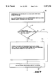
- FIG. 8 shows an exemplary embodiment of an initialization of measuring functions via an interface of the device.
- FIG. 1 side view
- FIG. 2 top view
- a measuring unit in the form of a measuring head 100 which, to execute a measurement in the direction of the arrow 110, is extendable from and reinsertable into the device 1.
- a measuring object e.g., a printed sheet
- a light source provided in the measuring head 100 and the light remitted from the printed sheet is received in the measuring head 100 and subsequently analyzed.
- the type of measurement (e.g., density measurement), the selection of individual parameters of the measurement, and/or the triggering of the measuring procedure (extension of the measuring head, etc.) can take place with the help of a handwheel 120 as an input unit and in each case can be displayed on a display unit, e.g, an LCD display 130 (FIG. 2).
- these inputs can also take place by means of, for example, a keyboard.
- the values measured are displayed on the LCD display 130 after the measurement.
- the hand-held device according to the invention corresponds to the state of the art as it is described, for example, in EP-A-0,603,448 mentioned in the beginning.
- the individual measuring functions are typically stored as programs in a first non-volatile memory 15, e.g., in a ROM (Read Only Memory), as is illustrated in the FIG. 3 block diagram, which shows the FIG. 1 device 1 according to an exemplary embodiment of the present invention in greater detail.
- a control unit in the form of a control computer 14 controls all sequences in the device.
- the device comprises an input unit 12 that is, in an exemplary embodiment, implemented as the handwheel 120 shown in FIG. 1 and FIG. 2.
- this input unit 12 can also be implemented as any other type of user controlled device, such as a keyboard.
- FIG. 1 a first non-volatile memory
- FIG. 3 shows the FIG. 3 block diagram, which shows the FIG. 3 device 1 device 1 according to an exemplary embodiment of the present invention in greater detail.
- the device comprises an input unit 12 that is, in an exemplary embodiment, implemented as the handwheel 120 shown in FIG. 1 and FIG. 2.
- this input unit 12 can also be implemented as any other type of user controlled device, such
- the device comprises a measuring system 10 that can correspond to any state of the art measuring system and can, in an exemplary embodiment, be produced as a measuring head 100 (FIG. 1, FIG. 2).
- the device also comprises a second non-volatile memory 16, e.g., an EEPROM (Electrically Erasable Programmable ROM), a volatile memory 17, e.g., a RAM (Random Access Memory) buffered by means of a battery 170, a display 13 (which corresponds to display 130 of FIG. 2) as well as an interface 18 for communication with external devices.
- EEPROM Electrically Erasable Programmable ROM
- RAM Random Access Memory
- the EEPROM 16 (second non-volatile memory) is shown in FIG. 4 in a block diagram.
- the EEPROM 16 comprises a lock 161 and a non-volatile programmable memory 161.
- the lock can be any means for inhibiting access to the memory 161 by the control unit 14 (e.g., coded access).
- the lock 150 To be able to access the memory 160, the lock 150 must first be opened each time by means of, for example, a matching key (e.g., a matching code). This key is preferably unique (that is, different) for each individual device for security reasons.
- release codes can be called up every time a measuring function is to be executed, the release codes being called up from the EEPROM 16 via the control computer 14.
- the release codes can also be copied to the volatile memory 17, which is battery-buffered by means of the battery 170.
- the release codes can thus remain preserved in the RAM 17.
- a RAM, such as the RAM 17, can only be manipulated with great difficulty, which is why no special protective measures are provided for the RAM in accordance with exemplary embodiments. However, such protection can be provided if desired.
- FIG. 5 illustrates how the procedures of an exemplary embodiment run when the device is switched on.
- a RAM inquiry takes place; namely, it is first determined whether release codes are already stored in the RAM 17, and secondly whether a checksum, calculated and stored when the device is switched off, is correct. If no release codes are stored in the RAM 17, either the device is being switched on for the first time or the release codes have been deleted from the RAM 17. This can occur when, for example, the EEPROM is replaced.
- the EEPROM 16 when the EEPROM 16 is to be replaced, its EEPROM memory 161 (FIG. 4) can be unlocked according to step 212 by means of the key stored, for example, in the ROM 15.
- the contents of the EEPROM 16, in particular the release codes stored in the memory 161 of the EEPROM, are then copied to the RAM 17 after the EEPROM has been replaced.
- the lock 160 of the EEPROM 16 is then locked again.
- Information is then stored in the RAM 17 to indicate that release codes have been copied to the RAM. Only then is further program execution at step 22 continued, because only then is the device in a state of readiness.
- the same sequence of steps also takes place, even when it is not the first time the device is being switched on, to detect whether a checksum stored in the RAM 17, is incorrect with respect to the release codes that are stored in the RAM 17. When incorrect, this means that changes have arisen in the RAM 17 that are attributable either to manipulations or to other causes.
- the same sequence of steps takes place as described in the preceding paragraph to store the release code of the EEPROM into the RAM 17. These two cases are represented by the path 211 and the step 212 in FIG. 5.
- the lock 160 (e.g., coded access) of the EEPROM 16 does not need to be unlocked and the contents of its memory 161 do not need to be copied to the RAM 17, either.
- the key to open the lock 160 of the EEPROM 16 thus does not need to be called up from the ROM 15, either.
- the key in exemplary embodiments, is only used for a single device, since preferably a different, unique key is stored in the ROM 15 of each device.
- an initialization code is input by means of the input unit 12 (e.g., by means of the FIG. 1 handwheel 120 or by means of a keyboard) in a first step 30.
- the initialization code can also be fed via the FIG. 3 interface 18 from an external computer, as will be explained later.
- This initialization code is segmented in a subsequent step 31 into a function number and a device code that is different for each device.
- the function number is interpreted; in other words, it is determined which release code or, respectively, which release codes are present in the initialization code for which functions. Furthermore, the corresponding initialization code is then read from the FIG. 3 RAM 17. Namely, the contents of the initialization codes for all measuring functions executable with the device are also stored in the buffered RAM 17. The initialization code fed in is then compared with the initialization codes stored in the RAM 17.
- a further step 33 it is determined whether the initialization code fed in concurs with the initialization code stored in the FIG. 3 RAM 17. If this is the case, the path 332 is taken. Then, in a further step 333, a release code is stored in the RAM 17, by means of which it is possible via the control unit 14 to access the additionally desired measuring functions in the ROM 15, i.e., the additionally desired measuring functions are "cleared”. Then, the lock 160 of the EEPROM 16 is unlocked, in that the key (“unlock codeb) is sent from ROM 15 to the lock of the EEPROM 16.
- a release code is also stored in the EEPROM 16, by means of which it is possible to access via the control unit 14 the additionally desired measuring functions in the ROM 15; in other words, it is stored in the EEPROM 16 that the additionally desired measuring functions have "cleared” such that the device 1 can be used to implement these desired functions. Subsequently, the lock 160 of the EEPROM 16 is locked again.
- step 33 In the event that the two initialization codes do not concur, i.en, the inquiry in step 33 is answered in the negative, the path 330 is taken. In a further step 331, either the "clearing" of additional measuring functions is then rejected, or possibly, as an alternative, certain additional measuring functions are “cleared”. This "clearing” then takes place as described in the preceding paragraph by means of the path 332 and the steps 333.
- This exemplary procedure makes it possible to easily upgrade the device without having to send the device to the manufacturer for lengthy periods.
- the user who would like to upgrade his device only needs to make sure that the right initialization codes are fed to his device. This can take place either in such a way that he orders initialization codes directly from the manufacturer, whereby the respective user is registered and a corresponding invoice can be made out to him.
- the user can also be left with an initialization code for free, for example, that makes it possible to access on a trial basis an additionally desired measuring function for a predetermined count value. This can take place as is explained below with the help of the flow chart of FIG. 7.
- a first step 40 an initialization code is fed to the device.
- the initialization code fed in is compared with the corresponding initialization code that is stored in the RAM 17.
- step 41 If both inquiries in step 41 are answered in the affirmative, i.e., the initialization codes concur, and if the additional measuring functions were not already "cleared” on a trial basis previously, the path 411 is taken. In a subsequent step 412, it is then stored in the RAM 17 that the additional measuring functions are "cleared". Furthermore, it is established in the RAM 17 that the additional measuring functions are "cleared” on a trial basis (i.e., that by means of a corresponding release code, the measuring function stored in the ROM 15 can be accessed on a trial basis). In addition, a counter for these measuring functions is set at "0". This counter is incremented each time these additional functions are accessed.
- the lock 160 of the EEPROM 16 is then unlocked, in that the key is sent from the ROM 15 to the lock 160 of the EEPROM 16.
- the memory 161 of the EEPROM 16 it is then stored that the additionally desired functions were already cleared previously on a trial basis. Finally, the lock 160 of the EEPROM 16 is locked again.
- step 41 If only one of the questions in step 41 is answered in the negative, i.e., if either the initialization codes do not concur or the measuring functions desired additionally on a trial basis were already "cleared” on a trial basis previously, the path 410 is taken and the measuring functions desired additionally on a trial basis are not "cleared".
- the result can be displayed on the display unit 13 in a step 42.
- an exemplary variant has been discussed in which the user obtains by himself the initialization codes from the manufacturer of the device and/or asks for them from the manufacturer and then feeds the initialization codes to the device himself (e.g., by hand-wheel 120 or via a keyboard).
- the upgrading of a device can also take place in such a way that the user brings his device on site to the corresponding representative and the upgrading of the device takes place there.
- the upgrading of the device can take place as explained below with reference to FIG. 8.
- the user brings his device on site to the representative and informs the representative what additional measuring functions he would like to execute with his device.
- the representative on site connects the device via the FIG. 3 interface 18 to a first computer 50 shown in FIG. 8.
- the first computer 50 is connected via a modem 51 and via another modem 61 with a second computer 60.
- This second computer 60 is at the device manufacturer's location. All initialization codes, release codes, device codes, etc. for each individual device 1 produced are stored in the memory of this second computer 60.
- the corresponding initialization codes are called up from the memory of the second computer 60 and transmitted via the modem 61, via a connection line (e.g., a phone line) and the modem 51 to the first computer 50. From there, they are fed via the interface 18 to the device 1, and the measuring functions are initialized in the already explained manner.
- a connection line e.g., a phone line
- the first computer 50 must first identify itself with the second computer 60 before the corresponding initialization codes are called up from the memory of the second computer 60 and transmitted to the first computer 50, it is also possible to automatically make out an invoice to the representative, since the first computer 50 of the representative is known, after its identification, to the second computer 60 at the device manufacturer's location, and the device manufacturer thus knows to whom he must make out the invoice. On site, the representative then settles accounts with the respective user whose device has been upgraded.
- the initialization codes that are stored in the memory of the second computer 60 can be transmitted in encoded form.
- the initialization codes are first encoded by means of a codec 62 connected with the second computer and transmitted in coded form via the modem 61 and the modem 51 to the first computer 50.
- the initialization codes can be previously encoded by means of the computer 60.
- the coded initialization codes are decoded again with the help of another codec 52 connected with the first computer 50 and fed in decoded form via the interface 18 to the device 1.
- the only one who can utilize the initialization codes is someone who has, in addition to the corresponding device 1 (recall that the initialization codes are, in an exemplary embodiment, different for each device), also a corresponding codec 52 to decode the initialization codes transmitted in coded form. This increases the security during transmission of the initialization codes.
- the variant in which one can upgrade the device 1 in this way can be offered in particular to big customers such as representatives, since the representative must then also have the codec 52 and a corresponding computer 50. In principle, however, it would also be useable for larger private customers or anyone else.
- the storage of all initialization codes, all release codes, device codes, etc. at the device manufacturer's location also has the advantage that when, for example, the FIG. 3 EEPROM 16 is defective, the old EEPROM 16 can be reproduced again. If the service technician replaces the EEPROM 16, he can enter via the input unit 12 that no release codes are stored in the RAM 17. The method of procedure already described above then takes place when turning the device on. On the other had, if only the control computer 14 is defective, a new control computer can simplify be installed without further costly measures being necessary in the process. In the same way, the ROM 15, in which basically all measuring functions are always stored, can be replaced with no problem. To be able to use future program versions as well, only the communication protocol with the EEPROM 16 needs to be exactly the same at all times.
- the initialization codes for the "clearing" on a trial basis of measuring functions can also be stored in the ROM 15 and can, in an exemplary embodiment, be the same for all devices in order to simply the managing of the initialization codes for the "clearing" on a trial basis of measuring functions.
Abstract
Description
Claims (21)
Applications Claiming Priority (2)
| Application Number | Priority Date | Filing Date | Title |
|---|---|---|---|
| EP94810485A EP0698785B1 (en) | 1994-08-24 | 1994-08-24 | Computer controlled device for detecting optical transmission and/or reemission properties of an object, method of operating such a device and method of initializing the measurement functions of such a device |
| EP94810485 | 1994-08-24 |
Publications (1)
| Publication Number | Publication Date |
|---|---|
| US5987396A true US5987396A (en) | 1999-11-16 |
Family
ID=8218303
Family Applications (1)
| Application Number | Title | Priority Date | Filing Date |
|---|---|---|---|
| US08/517,678 Expired - Fee Related US5987396A (en) | 1994-08-24 | 1995-08-22 | Computer-controlled device for detecting optical transmission and/or remittance properties of a measuring object, method for operating such a device and method for initializing measuring functions of such a device |
Country Status (5)
| Country | Link |
|---|---|
| US (1) | US5987396A (en) |
| EP (1) | EP0698785B1 (en) |
| JP (1) | JP3760352B2 (en) |
| CA (1) | CA2156669A1 (en) |
| DE (1) | DE59409728D1 (en) |
Cited By (3)
| Publication number | Priority date | Publication date | Assignee | Title |
|---|---|---|---|---|
| US20020152049A1 (en) * | 1999-12-17 | 2002-10-17 | Lewis Mark D. | Computer-implemented method and apparatus for matching paint |
| US7194361B2 (en) | 1999-12-17 | 2007-03-20 | Ppg Industries Ohio, Inc. | Computer-implemented method and apparatus for matching paint |
| CN106936495A (en) * | 2017-03-23 | 2017-07-07 | 厦门优迅高速芯片有限公司 | The automatic testing equipment and method of a kind of smooth transceiving chip |
Families Citing this family (1)
| Publication number | Priority date | Publication date | Assignee | Title |
|---|---|---|---|---|
| EP0913674A1 (en) | 1997-10-31 | 1999-05-06 | Gretag-Macbeth AG | Computer controlled measuring device |
Citations (6)
| Publication number | Priority date | Publication date | Assignee | Title |
|---|---|---|---|---|
| US4242730A (en) * | 1979-03-09 | 1980-12-30 | Helena Laboratories Corporation | Single scan microprocessor-controlled densitometer |
| WO1985002310A1 (en) * | 1983-11-14 | 1985-05-23 | Softnet, Incorporated | Software distribution system |
| US4740890A (en) * | 1983-12-22 | 1988-04-26 | Software Concepts, Inc. | Software protection system with trial period usage code and unlimited use unlocking code both recorded on program storage media |
| US4937764A (en) * | 1987-05-06 | 1990-06-26 | Fuji Photo Film Co., Ltd. | Method of optical density measurement and apparatus therefor |
| US5214697A (en) * | 1990-03-27 | 1993-05-25 | Kabushiki Kaisha Toshiba | Program execution apparatus for ensuring security of a program |
| EP0603448A1 (en) * | 1992-12-23 | 1994-06-29 | GRETAG Aktiengesellschaft | Hand-held densitometer |
-
1994
- 1994-08-24 EP EP94810485A patent/EP0698785B1/en not_active Expired - Lifetime
- 1994-08-24 DE DE59409728T patent/DE59409728D1/en not_active Expired - Fee Related
-
1995
- 1995-08-22 CA CA002156669A patent/CA2156669A1/en not_active Abandoned
- 1995-08-22 US US08/517,678 patent/US5987396A/en not_active Expired - Fee Related
- 1995-08-24 JP JP23908695A patent/JP3760352B2/en not_active Expired - Fee Related
Patent Citations (6)
| Publication number | Priority date | Publication date | Assignee | Title |
|---|---|---|---|---|
| US4242730A (en) * | 1979-03-09 | 1980-12-30 | Helena Laboratories Corporation | Single scan microprocessor-controlled densitometer |
| WO1985002310A1 (en) * | 1983-11-14 | 1985-05-23 | Softnet, Incorporated | Software distribution system |
| US4740890A (en) * | 1983-12-22 | 1988-04-26 | Software Concepts, Inc. | Software protection system with trial period usage code and unlimited use unlocking code both recorded on program storage media |
| US4937764A (en) * | 1987-05-06 | 1990-06-26 | Fuji Photo Film Co., Ltd. | Method of optical density measurement and apparatus therefor |
| US5214697A (en) * | 1990-03-27 | 1993-05-25 | Kabushiki Kaisha Toshiba | Program execution apparatus for ensuring security of a program |
| EP0603448A1 (en) * | 1992-12-23 | 1994-06-29 | GRETAG Aktiengesellschaft | Hand-held densitometer |
Non-Patent Citations (6)
| Title |
|---|
| Catalyst Semiconductor DataBook 92/93, CAT35C704/CAT35C7041 4K Bit Secure Access Serial E 2 PROM, 1992 by Catalyst Semiconductor, Inc., title page and pp. 6 14 through 6 27. * |
| Catalyst Semiconductor DataBook 92/93, CAT35C704/CAT35C7041 4K-Bit Secure Access Serial E2 PROM, 1992 by Catalyst Semiconductor, Inc., title page and pp. 6-14 through 6-27. |
| Handbuch f u r Hardlock E Y E, Fast Electronic GmbH, Version 2.1, Dec. 1, 1989, Munchen, Germany, pp. 2 1 through 2 7. * |
| Handbuch fur Hardlock E-Y-E, Fast Electronic GmbH, Version 2.1, Dec. 1, 1989, Munchen, Germany, pp. 2-1 through 2-7. |
| IBM Technical Disclosure Bulletin, "Method for Creating Many Individually-Distributable Programs On a Single Diskette", S.R. White, vol. 27, No. 7A, Dec. 1984, pp. 3903-3904. |
| IBM Technical Disclosure Bulletin, Method for Creating Many Individually Distributable Programs On a Single Diskette , S.R. White, vol. 27, No. 7A, Dec. 1984, pp. 3903 3904. * |
Cited By (8)
| Publication number | Priority date | Publication date | Assignee | Title |
|---|---|---|---|---|
| US20020152049A1 (en) * | 1999-12-17 | 2002-10-17 | Lewis Mark D. | Computer-implemented method and apparatus for matching paint |
| US6522977B2 (en) | 1999-12-17 | 2003-02-18 | Ppg Industries Ohio, Inc. | Computer-implemented method and apparatus for matching paint |
| US7194361B2 (en) | 1999-12-17 | 2007-03-20 | Ppg Industries Ohio, Inc. | Computer-implemented method and apparatus for matching paint |
| US7337162B2 (en) | 1999-12-17 | 2008-02-26 | Ppg Industries Ohio, Inc. | Computer-implemented method and apparatus for matching paint |
| US20080147348A1 (en) * | 1999-12-17 | 2008-06-19 | Ppg Industries Ohio, Inc. | Computer-implemented method and apparatus for matching paint |
| US7860856B2 (en) | 1999-12-17 | 2010-12-28 | Ppg Industries Ohio, Inc. | Computer-implemented method and apparatus for matching paint |
| CN106936495A (en) * | 2017-03-23 | 2017-07-07 | 厦门优迅高速芯片有限公司 | The automatic testing equipment and method of a kind of smooth transceiving chip |
| CN106936495B (en) * | 2017-03-23 | 2019-07-19 | 厦门优迅高速芯片有限公司 | A kind of automatic testing equipment and method of smooth transceiving chip |
Also Published As
| Publication number | Publication date |
|---|---|
| CA2156669A1 (en) | 1996-02-25 |
| DE59409728D1 (en) | 2001-05-17 |
| JPH0875647A (en) | 1996-03-22 |
| EP0698785B1 (en) | 2001-04-11 |
| EP0698785A1 (en) | 1996-02-28 |
| JP3760352B2 (en) | 2006-03-29 |
Similar Documents
| Publication | Publication Date | Title |
|---|---|---|
| US6694221B2 (en) | Controlled inventory device and method using pressure transducer | |
| EP0670036B1 (en) | Programmable spectrophotometer | |
| US6643843B1 (en) | Methods and apparatus for optical communication update of program memory in embedded systems | |
| US5386455A (en) | System and method for automatic activation of cellular telephones | |
| WO2000040829A1 (en) | Electronic supervisor and subordinate lock system | |
| US4495627A (en) | Cash accounting system | |
| US5444517A (en) | Management system for controlling operation of an image processing apparatus | |
| US4570223A (en) | Cash register control system for authorization of selected operator functions | |
| US5414753A (en) | Number assignment module setting system for portable telephone set | |
| US5661285A (en) | Self-service, banking system | |
| JP2867720B2 (en) | Mechanism and method for preventing unauthorized access to ROM incorporated in radio selective call receiver | |
| US5987396A (en) | Computer-controlled device for detecting optical transmission and/or remittance properties of a measuring object, method for operating such a device and method for initializing measuring functions of such a device | |
| US5933583A (en) | Communication control apparatus for a printing system | |
| KR200431950Y1 (en) | Measuring device for tint of car and management system thereof | |
| KR100807181B1 (en) | Measuring device for tint of car and management system thereof | |
| RU2269160C2 (en) | Device for processing documents | |
| EP1043699A1 (en) | Money validation | |
| JP4543539B2 (en) | Vending machines, vending machine user management devices, and vending machine sales restriction systems | |
| GB2331820A (en) | Document platforms | |
| JPH09270050A (en) | Cash transaction device | |
| KR100580569B1 (en) | Delivery freight transit locker and managing method of delivery freight transit system | |
| CA2494885C (en) | Apparatus and method for issuing documents of value | |
| JPS62154060A (en) | Identification number input system | |
| EP0690417A2 (en) | Postage meter having electronic access control security | |
| KR950003797B1 (en) | Endorsement method for cash register |
Legal Events
| Date | Code | Title | Description |
|---|---|---|---|
| AS | Assignment |
Owner name: GRETAG AKTIENGESELLSCHAFT, SWITZERLAND Free format text: ASSIGNMENT OF ASSIGNORS INTEREST;ASSIGNORS:BERNER, MARKUS;SENN, THOMAS;REEL/FRAME:007633/0860 Effective date: 19950712 |
|
| FEPP | Fee payment procedure |
Free format text: PAYOR NUMBER ASSIGNED (ORIGINAL EVENT CODE: ASPN); ENTITY STATUS OF PATENT OWNER: LARGE ENTITY |
|
| AS | Assignment |
Owner name: GRETAG-MACBETH AG, SWITZERLAND Free format text: ASSIGNMENT OF ASSIGNORS INTEREST;ASSIGNOR:GRETAG AKTIENGESELLSCHAFT;REEL/FRAME:011400/0704 Effective date: 20001215 |
|
| AS | Assignment |
Owner name: EASTMAN KODAK, NEW YORK Free format text: SECURITY INTEREST;ASSIGNORS:GRETAG IMAGING HOLDING AG;GRETAG IMAGING TRADING AG;GRETAG IMAGING AG;AND OTHERS;REEL/FRAME:013193/0762 Effective date: 20020327 |
|
| FPAY | Fee payment |
Year of fee payment: 4 |
|
| FPAY | Fee payment |
Year of fee payment: 8 |
|
| REMI | Maintenance fee reminder mailed | ||
| LAPS | Lapse for failure to pay maintenance fees | ||
| STCH | Information on status: patent discontinuation |
Free format text: PATENT EXPIRED DUE TO NONPAYMENT OF MAINTENANCE FEES UNDER 37 CFR 1.362 |
|
| FP | Lapsed due to failure to pay maintenance fee |
Effective date: 20111116 |