US5986621A - Stub loaded helix antenna - Google Patents
Stub loaded helix antenna Download PDFInfo
- Publication number
- US5986621A US5986621A US08/888,324 US88832497A US5986621A US 5986621 A US5986621 A US 5986621A US 88832497 A US88832497 A US 88832497A US 5986621 A US5986621 A US 5986621A
- Authority
- US
- United States
- Prior art keywords
- helix
- antenna
- stub
- radius
- length
- Prior art date
- Legal status (The legal status is an assumption and is not a legal conclusion. Google has not performed a legal analysis and makes no representation as to the accuracy of the status listed.)
- Expired - Lifetime
Links
Images


Classifications
-
- H—ELECTRICITY
- H01—ELECTRIC ELEMENTS
- H01Q—ANTENNAS, i.e. RADIO AERIALS
- H01Q1/00—Details of, or arrangements associated with, antennas
- H01Q1/36—Structural form of radiating elements, e.g. cone, spiral, umbrella; Particular materials used therewith
- H01Q1/362—Structural form of radiating elements, e.g. cone, spiral, umbrella; Particular materials used therewith for broadside radiating helical antennas
-
- H—ELECTRICITY
- H01—ELECTRIC ELEMENTS
- H01Q—ANTENNAS, i.e. RADIO AERIALS
- H01Q11/00—Electrically-long antennas having dimensions more than twice the shortest operating wavelength and consisting of conductive active radiating elements
- H01Q11/02—Non-resonant antennas, e.g. travelling-wave antenna
- H01Q11/08—Helical antennas
-
- H—ELECTRICITY
- H01—ELECTRIC ELEMENTS
- H01Q—ANTENNAS, i.e. RADIO AERIALS
- H01Q1/00—Details of, or arrangements associated with, antennas
- H01Q1/36—Structural form of radiating elements, e.g. cone, spiral, umbrella; Particular materials used therewith
-
- H—ELECTRICITY
- H01—ELECTRIC ELEMENTS
- H01Q—ANTENNAS, i.e. RADIO AERIALS
- H01Q1/00—Details of, or arrangements associated with, antennas
- H01Q1/48—Earthing means; Earth screens; Counterpoises
-
- H—ELECTRICITY
- H01—ELECTRIC ELEMENTS
- H01Q—ANTENNAS, i.e. RADIO AERIALS
- H01Q9/00—Electrically-short antennas having dimensions not more than twice the operating wavelength and consisting of conductive active radiating elements
- H01Q9/04—Resonant antennas
- H01Q9/16—Resonant antennas with feed intermediate between the extremities of the antenna, e.g. centre-fed dipole
- H01Q9/26—Resonant antennas with feed intermediate between the extremities of the antenna, e.g. centre-fed dipole with folded element or elements, the folded parts being spaced apart a small fraction of operating wavelength
- H01Q9/27—Spiral antennas
Definitions
- the present invention generally relates to helical antennas, and more particularly to helical antenna geometries which support reduced antenna size.
- the helical antenna is old in the art, having first appeared in the late 1940's.
- a length of conducting material is wound at a radius and with a pitch angle around a central axis.
- the radius of curvature of the helix is defined by the radius of the enclosing cylinder.
- the helix antenna produces a directional antenna pattern, generates circularly polarized radio waves, and has a wide operational frequency bandwidth.
- the antenna may be the largest component of the system. Thus there is a need for a way to reduce antenna size without reducing antenna performance.
- the present invention is an improved geometry for a helical antenna.
- a helical antenna Along its length are a plurality of stubs which project from the outer radius of curvature of the helix toward the central axis of the helix.
- the stubs are not in electrical contact with one another.
- the stub loaded helical geometry is defined by a) the circumference of the helix (which is 2 ⁇ times the radius of the enclosing cylinder), b) the number of turns of the helix, c) the pitch angle of the helical windings, d) the number of stubs per turn, e) the depth of the stubs, and f) the angular width of each stub (i.e.
- a stub loaded helix antenna in accordance with the invention exhibits performance characteristics such as gain and circular polarization similar to the traditional helical antenna, but is approximately one third smaller in diameter and one-half as long.
- the stub loaded helix antenna can be used in wireless local area networks, satellite communications, microwave point-to-point systems, and personal communication systems. The antenna is most useful in applications which use frequencies from the low VHF to low microwave range.
- FIG. 1 is a top view of a single turn of a stub loaded helix antenna.
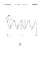
- FIG. 2 is a side view of a four turn stub loaded helix antenna.
- FIG. 3 is an oblique view of a stub loaded helix antenna.
- FIG. 1 there is shown a top view of a single turn of a stub loaded helix antenna.
- the antenna is formed from a continuous length of conducting material.
- the distance from the center 10 to the circumference 11 of the enclosing cylinder of the helix is a radius "R" (hereinafter called “radius of the helix” or “helix radius”).
- the diameter "D" of the helix is the diameter (2R) of the enclosing cylinder, and the circumference of the enclosing cylinder is "C”.
- Each stub 12 (four are shown in this example) is formed by bending the conducting material at approximately right angles from the circumference at points 13 and 13' toward the center 10 extending a distance "d", less than radius "R".
- the angular width ⁇ of the stub 12 is the angle subtended by the arc defined by the width of the stub at the radius of the enclosing cylinder (i.e. between points 13 and 13').
- n number
- each stub has a depth of about two thirds of a radius and is truncated in a side 14 of length "s".
- n need not be an integer, nor need it be the same from turn to turn, although it would be the same in typical implementations.
- s would be less than the width of the stub at the radius, and could be zero so that the stub end in the direction of the center axis is pointed (as indicated in FIG. 3).
- FIG. 2 there is shown a side view of a stub loaded helix antenna.
- the helix has a pitch angle a, which is measured by taking a tangent 21 along the helix curve length and, at the point where the tangent meets the enclosing cylinder defined by the helix, taking another tangent 22 which lies in a plane perpendicular to the central axis of the helix. If the length of the central axis of the helix is "L" and the length of a single helical turn without stubs is "T d ", then ##EQU2## where "N" is the number of turns in the helix.
- the actual length of conductor in a single turn of the stub loaded helix antenna is not "T d " (which is the length of a helical turn without stubs). From “T d " there must be subtracted the length corresponding to the angular width of the stubs (yielding an angular component of 2 ⁇ -n ⁇ ), and then there must be added the length of conductor taken by the stubs. In the example shown in FIG. 1, the conductor length taken by each stub is
- FIG. 3 shows an oblique view of an antenna in accordance with the invention, having a stub loaded helical winding mounted on a reflector 30 in the conventional manner, with the central axis 31 of the helix being along the beam axis of the reflector.
- the pitch angle is in the range of 7° to 9°
- the number of stubs per turn may range from 3 to 15, the number of turns may range from 4 to 10
- the depth of stubs may range from two-thirds to three-quarters of a helix radius.
- Other embodiments of the invention may show different, yet still significant, levels of size reduction over a conventional helix antenna having comparable performance characteristics.
Abstract
Description
S.sub.L =(2d+s)
Claims (16)
Priority Applications (14)
| Application Number | Priority Date | Filing Date | Title |
|---|---|---|---|
| US08/888,324 US5986621A (en) | 1997-07-03 | 1997-07-03 | Stub loaded helix antenna |
| PT98935538T PT1016164E (en) | 1997-07-03 | 1998-07-02 | HELICOIDAL ANTENNA PROVIDED BY TALOES |
| ES98935538T ES2226158T3 (en) | 1997-07-03 | 1998-07-02 | HELICOIDAL ANTENNA LOADED OUTGOING. |
| AU84762/98A AU762172B2 (en) | 1997-07-03 | 1998-07-02 | Stub loaded helix antenna |
| JP50745299A JP3959123B2 (en) | 1997-07-03 | 1998-07-02 | Stub-formed spiral antenna |
| PCT/US1998/013952 WO1999001908A1 (en) | 1997-07-03 | 1998-07-02 | Stub loaded helix antenna |
| BR9811656-8A BR9811656A (en) | 1997-07-03 | 1998-07-02 | Helical antenna with rods |
| EP98935538A EP1016164B1 (en) | 1997-07-03 | 1998-07-02 | Stub loaded helix antenna |
| DE69826500T DE69826500T2 (en) | 1997-07-03 | 1998-07-02 | THREADED ANTENNA ANTENNA WITH CROSS-LINKED ELEMENTS |
| CN98806838A CN1130796C (en) | 1997-07-03 | 1998-07-02 | Stub loaded helix antenna |
| AT98935538T ATE277430T1 (en) | 1997-07-03 | 1998-07-02 | HELICAL ANTENNA PROVIDED WITH CROSS ELEMENTS |
| KR10-1999-7012488A KR100489795B1 (en) | 1997-07-03 | 1998-07-02 | Stub loaded helix antenna |
| CA002295171A CA2295171C (en) | 1997-07-03 | 1998-07-02 | Stub loaded helix antenna |
| HK01100554A HK1029870A1 (en) | 1997-07-03 | 2001-01-22 | Stub loaded helix antenna |
Applications Claiming Priority (1)
| Application Number | Priority Date | Filing Date | Title |
|---|---|---|---|
| US08/888,324 US5986621A (en) | 1997-07-03 | 1997-07-03 | Stub loaded helix antenna |
Publications (1)
| Publication Number | Publication Date |
|---|---|
| US5986621A true US5986621A (en) | 1999-11-16 |
Family
ID=25392978
Family Applications (1)
| Application Number | Title | Priority Date | Filing Date |
|---|---|---|---|
| US08/888,324 Expired - Lifetime US5986621A (en) | 1997-07-03 | 1997-07-03 | Stub loaded helix antenna |
Country Status (14)
| Country | Link |
|---|---|
| US (1) | US5986621A (en) |
| EP (1) | EP1016164B1 (en) |
| JP (1) | JP3959123B2 (en) |
| KR (1) | KR100489795B1 (en) |
| CN (1) | CN1130796C (en) |
| AT (1) | ATE277430T1 (en) |
| AU (1) | AU762172B2 (en) |
| BR (1) | BR9811656A (en) |
| CA (1) | CA2295171C (en) |
| DE (1) | DE69826500T2 (en) |
| ES (1) | ES2226158T3 (en) |
| HK (1) | HK1029870A1 (en) |
| PT (1) | PT1016164E (en) |
| WO (1) | WO1999001908A1 (en) |
Cited By (9)
| Publication number | Priority date | Publication date | Assignee | Title |
|---|---|---|---|---|
| US6147660A (en) * | 1997-06-03 | 2000-11-14 | Galtronics Ltd. | Molded antenna |
| US20010045914A1 (en) * | 2000-02-25 | 2001-11-29 | Bunker Philip Alan | Device and system for providing a wireless high-speed communications network |
| US6373448B1 (en) | 2001-04-13 | 2002-04-16 | Luxul Corporation | Antenna for broadband wireless communications |
| US6738026B1 (en) | 2002-12-09 | 2004-05-18 | Centurion Wireless Technologies, Inc. | Low profile tri-filar, single feed, helical antenna |
| US20050270263A1 (en) * | 2004-06-08 | 2005-12-08 | Samsung Electronics Co., Ltd. | Source driver and a source line driving method using a gamma driving scheme for a liquid crystal display (LCD) |
| US20060208080A1 (en) * | 2004-11-05 | 2006-09-21 | Goliath Solutions Llc. | Distributed RFID antenna array utilizing circular polarized helical antennas |
| US7414591B1 (en) | 2005-08-26 | 2008-08-19 | Lockheed Martin Corporation | Helical antenna system |
| US10461410B2 (en) | 2017-02-01 | 2019-10-29 | Calamp Wireless Networks Corporation | Coaxial helix antennas |
| US11799188B2 (en) * | 2015-11-05 | 2023-10-24 | Thales Dis France Sas | Method for manufacturing a radiofrequency antenna on a substrate and antenna thus obtained |
Families Citing this family (1)
| Publication number | Priority date | Publication date | Assignee | Title |
|---|---|---|---|---|
| KR100822470B1 (en) | 2006-08-29 | 2008-04-16 | 삼성전자주식회사 | Helical antenna operating low frequency band having a open stub |
Citations (14)
| Publication number | Priority date | Publication date | Assignee | Title |
|---|---|---|---|---|
| US2495399A (en) * | 1946-09-17 | 1950-01-24 | Hazeltine Research Inc | Antenna system |
| US3524193A (en) * | 1967-08-24 | 1970-08-11 | Electronic Communications | Collapsible helical antenna |
| US3716861A (en) * | 1971-03-22 | 1973-02-13 | J Root | Serpentine antenna mounted on a rotatable capacitive coupler |
| US4475111A (en) * | 1982-02-16 | 1984-10-02 | General Electric Company | Portable collapsing antenna |
| US5146234A (en) * | 1989-09-08 | 1992-09-08 | Ball Corporation | Dual polarized spiral antenna |
| US5162806A (en) * | 1990-02-05 | 1992-11-10 | Raytheon Company | Planar antenna with lens for controlling beam widths from two portions thereof at different frequencies |
| US5313216A (en) * | 1991-05-03 | 1994-05-17 | Georgia Tech Research Corporation | Multioctave microstrip antenna |
| US5341148A (en) * | 1991-11-29 | 1994-08-23 | Trw Inc. | High frequency multi-turn loop antenna in cavity |
| US5346300A (en) * | 1991-07-05 | 1994-09-13 | Sharp Kabushiki Kaisha | Back fire helical antenna |
| US5349365A (en) * | 1991-10-21 | 1994-09-20 | Ow Steven G | Quadrifilar helix antenna |
| US5359340A (en) * | 1992-09-30 | 1994-10-25 | Fujitsu Limited | Helical antenna for portable radio communication equipment |
| US5450093A (en) * | 1994-04-20 | 1995-09-12 | The United States Of America As Represented By The Secretary Of The Navy | Center-fed multifilar helix antenna |
| US5457469A (en) * | 1991-01-24 | 1995-10-10 | Rdi Electronics, Incorporated | System including spiral antenna and dipole or monopole antenna |
| US5517206A (en) * | 1991-07-30 | 1996-05-14 | Ball Corporation | Broad band antenna structure |
Family Cites Families (4)
| Publication number | Priority date | Publication date | Assignee | Title |
|---|---|---|---|---|
| FR719837A (en) * | 1930-10-13 | 1932-02-10 | Telefunken Gmbh | Improvements to directional shortwave antennas |
| GB769080A (en) * | 1954-05-22 | 1957-02-27 | Denis Evald Reinhold Lander | Antenna for television and/or radio |
| US3568205A (en) * | 1968-02-12 | 1971-03-02 | Goodyear Aerospace Corp | Novel helical antenna |
| US5345248A (en) * | 1992-07-22 | 1994-09-06 | Space Systems/Loral, Inc. | Staggered helical array antenna |
-
1997
- 1997-07-03 US US08/888,324 patent/US5986621A/en not_active Expired - Lifetime
-
1998
- 1998-07-02 ES ES98935538T patent/ES2226158T3/en not_active Expired - Lifetime
- 1998-07-02 PT PT98935538T patent/PT1016164E/en unknown
- 1998-07-02 AT AT98935538T patent/ATE277430T1/en not_active IP Right Cessation
- 1998-07-02 EP EP98935538A patent/EP1016164B1/en not_active Expired - Lifetime
- 1998-07-02 CA CA002295171A patent/CA2295171C/en not_active Expired - Fee Related
- 1998-07-02 KR KR10-1999-7012488A patent/KR100489795B1/en not_active IP Right Cessation
- 1998-07-02 WO PCT/US1998/013952 patent/WO1999001908A1/en active IP Right Grant
- 1998-07-02 DE DE69826500T patent/DE69826500T2/en not_active Expired - Fee Related
- 1998-07-02 AU AU84762/98A patent/AU762172B2/en not_active Ceased
- 1998-07-02 CN CN98806838A patent/CN1130796C/en not_active Expired - Fee Related
- 1998-07-02 JP JP50745299A patent/JP3959123B2/en not_active Expired - Fee Related
- 1998-07-02 BR BR9811656-8A patent/BR9811656A/en not_active IP Right Cessation
-
2001
- 2001-01-22 HK HK01100554A patent/HK1029870A1/en not_active IP Right Cessation
Patent Citations (14)
| Publication number | Priority date | Publication date | Assignee | Title |
|---|---|---|---|---|
| US2495399A (en) * | 1946-09-17 | 1950-01-24 | Hazeltine Research Inc | Antenna system |
| US3524193A (en) * | 1967-08-24 | 1970-08-11 | Electronic Communications | Collapsible helical antenna |
| US3716861A (en) * | 1971-03-22 | 1973-02-13 | J Root | Serpentine antenna mounted on a rotatable capacitive coupler |
| US4475111A (en) * | 1982-02-16 | 1984-10-02 | General Electric Company | Portable collapsing antenna |
| US5146234A (en) * | 1989-09-08 | 1992-09-08 | Ball Corporation | Dual polarized spiral antenna |
| US5162806A (en) * | 1990-02-05 | 1992-11-10 | Raytheon Company | Planar antenna with lens for controlling beam widths from two portions thereof at different frequencies |
| US5457469A (en) * | 1991-01-24 | 1995-10-10 | Rdi Electronics, Incorporated | System including spiral antenna and dipole or monopole antenna |
| US5313216A (en) * | 1991-05-03 | 1994-05-17 | Georgia Tech Research Corporation | Multioctave microstrip antenna |
| US5346300A (en) * | 1991-07-05 | 1994-09-13 | Sharp Kabushiki Kaisha | Back fire helical antenna |
| US5517206A (en) * | 1991-07-30 | 1996-05-14 | Ball Corporation | Broad band antenna structure |
| US5349365A (en) * | 1991-10-21 | 1994-09-20 | Ow Steven G | Quadrifilar helix antenna |
| US5341148A (en) * | 1991-11-29 | 1994-08-23 | Trw Inc. | High frequency multi-turn loop antenna in cavity |
| US5359340A (en) * | 1992-09-30 | 1994-10-25 | Fujitsu Limited | Helical antenna for portable radio communication equipment |
| US5450093A (en) * | 1994-04-20 | 1995-09-12 | The United States Of America As Represented By The Secretary Of The Navy | Center-fed multifilar helix antenna |
Cited By (11)
| Publication number | Priority date | Publication date | Assignee | Title |
|---|---|---|---|---|
| US6147660A (en) * | 1997-06-03 | 2000-11-14 | Galtronics Ltd. | Molded antenna |
| US20010045914A1 (en) * | 2000-02-25 | 2001-11-29 | Bunker Philip Alan | Device and system for providing a wireless high-speed communications network |
| US6373448B1 (en) | 2001-04-13 | 2002-04-16 | Luxul Corporation | Antenna for broadband wireless communications |
| US6738026B1 (en) | 2002-12-09 | 2004-05-18 | Centurion Wireless Technologies, Inc. | Low profile tri-filar, single feed, helical antenna |
| US20040108964A1 (en) * | 2002-12-09 | 2004-06-10 | Mckivergan Patrick Daniel | Low profile tri-filar, single feed, helical antenna |
| US20050270263A1 (en) * | 2004-06-08 | 2005-12-08 | Samsung Electronics Co., Ltd. | Source driver and a source line driving method using a gamma driving scheme for a liquid crystal display (LCD) |
| US20060208080A1 (en) * | 2004-11-05 | 2006-09-21 | Goliath Solutions Llc. | Distributed RFID antenna array utilizing circular polarized helical antennas |
| US7614556B2 (en) * | 2004-11-05 | 2009-11-10 | Goliath Solutions, Llc | Distributed RFID antenna array utilizing circular polarized helical antennas |
| US7414591B1 (en) | 2005-08-26 | 2008-08-19 | Lockheed Martin Corporation | Helical antenna system |
| US11799188B2 (en) * | 2015-11-05 | 2023-10-24 | Thales Dis France Sas | Method for manufacturing a radiofrequency antenna on a substrate and antenna thus obtained |
| US10461410B2 (en) | 2017-02-01 | 2019-10-29 | Calamp Wireless Networks Corporation | Coaxial helix antennas |
Also Published As
| Publication number | Publication date |
|---|---|
| CA2295171A1 (en) | 1999-01-14 |
| CN1130796C (en) | 2003-12-10 |
| CN1261991A (en) | 2000-08-02 |
| CA2295171C (en) | 2005-10-18 |
| HK1029870A1 (en) | 2001-04-12 |
| BR9811656A (en) | 2000-09-19 |
| EP1016164A1 (en) | 2000-07-05 |
| KR100489795B1 (en) | 2005-05-16 |
| JP3959123B2 (en) | 2007-08-15 |
| WO1999001908A1 (en) | 1999-01-14 |
| PT1016164E (en) | 2005-01-31 |
| EP1016164B1 (en) | 2004-09-22 |
| AU8476298A (en) | 1999-01-25 |
| DE69826500T2 (en) | 2005-09-29 |
| KR20010020573A (en) | 2001-03-15 |
| JP2002508138A (en) | 2002-03-12 |
| EP1016164A4 (en) | 2003-05-14 |
| ES2226158T3 (en) | 2005-03-16 |
| AU762172B2 (en) | 2003-06-19 |
| DE69826500D1 (en) | 2004-10-28 |
| ATE277430T1 (en) | 2004-10-15 |
Similar Documents
| Publication | Publication Date | Title |
|---|---|---|
| JP3564308B2 (en) | antenna | |
| US5467095A (en) | Low profile antenna | |
| US4658258A (en) | Taperd horn antenna with annular choke channel | |
| US6731243B2 (en) | Planar antenna device | |
| US5986621A (en) | Stub loaded helix antenna | |
| JP2002530982A (en) | Broadband small slow wave antenna | |
| JP2005137032A (en) | Antenna | |
| EP0877442A2 (en) | Helical antenna | |
| US7079078B2 (en) | Patch antenna apparatus preferable for receiving ground wave and signal wave from low elevation angle satellite | |
| US6628241B1 (en) | Antenna device and communication terminal comprising the same | |
| EP0394960A1 (en) | A microstrip antenna | |
| EP1026777A2 (en) | Broad band spiral and sinuous antennas | |
| JP2007158826A (en) | Antenna device | |
| JPS59193605A (en) | Dipole antenna | |
| JP4473113B2 (en) | Trapezoidal element antenna | |
| US4296416A (en) | Dual mode log periodic monopole array | |
| KR100468201B1 (en) | Microstrip Spiral Antenna Having Two-Spiral Line | |
| CN217062519U (en) | Small cylindrical conformal antenna | |
| Nakano et al. | Frequency characteristics of tapered backfire helical antenna with loaded termination | |
| JP2606139Y2 (en) | Dual frequency antenna device | |
| CN116315619B (en) | Ultra-wideband high-gain helical antenna | |
| JP5043774B2 (en) | Microstrip line antenna | |
| JPH0324804B2 (en) | ||
| CA2244407C (en) | Low profile mobile satellite antenna | |
| RU2097881C1 (en) | Oscillating and passive ribbon dipoles |
Legal Events
| Date | Code | Title | Description |
|---|---|---|---|
| AS | Assignment |
Owner name: VIRGINIA POLYTECHNIC INSTITUTE AND STATE UNIVERSIT Free format text: ASSIGNMENT OF ASSIGNORS INTEREST;ASSIGNORS:BARTS, R. MICHAEL;STUTZMAN, WARREN L.;REEL/FRAME:008911/0888 Effective date: 19970711 Owner name: VIRGINIA TECH INTELLECTUAL PROPERTIES, INC., VIRGI Free format text: ASSIGNMENT OF ASSIGNORS INTEREST;ASSIGNOR:VIRGINIA POLYTECHNIC INSTITUTE & STATE UNIVERSITY;REEL/FRAME:008911/0890 Effective date: 19970717 |
|
| STCF | Information on status: patent grant |
Free format text: PATENTED CASE |
|
| FEPP | Fee payment procedure |
Free format text: PAYOR NUMBER ASSIGNED (ORIGINAL EVENT CODE: ASPN); ENTITY STATUS OF PATENT OWNER: SMALL ENTITY |
|
| FPAY | Fee payment |
Year of fee payment: 4 |
|
| FPAY | Fee payment |
Year of fee payment: 8 |
|
| SULP | Surcharge for late payment |
Year of fee payment: 7 |
|
| FPAY | Fee payment |
Year of fee payment: 12 |