US5982813A - Demand-based power and data rate adjustments to a transmitter to optimize channel capacity and power usage with respect to data transmission traffic over a fixed-bandwidth channel - Google Patents
Demand-based power and data rate adjustments to a transmitter to optimize channel capacity and power usage with respect to data transmission traffic over a fixed-bandwidth channel Download PDFInfo
- Publication number
- US5982813A US5982813A US08/723,406 US72340696A US5982813A US 5982813 A US5982813 A US 5982813A US 72340696 A US72340696 A US 72340696A US 5982813 A US5982813 A US 5982813A
- Authority
- US
- United States
- Prior art keywords
- data rate
- rate
- transmit
- data
- channel
- Prior art date
- Legal status (The legal status is an assumption and is not a legal conclusion. Google has not performed a legal analysis and makes no representation as to the accuracy of the status listed.)
- Ceased
Links
- 230000005540 biological transmission Effects 0.000 title description 15
- 238000004891 communication Methods 0.000 claims abstract description 62
- 238000000034 method Methods 0.000 claims abstract description 17
- 230000003595 spectral effect Effects 0.000 claims abstract description 7
- 230000004044 response Effects 0.000 claims description 4
- 230000008859 change Effects 0.000 claims description 3
- 239000000969 carrier Substances 0.000 claims 1
- 102100026758 Serine/threonine-protein kinase 16 Human genes 0.000 description 26
- 101710184778 Serine/threonine-protein kinase 16 Proteins 0.000 description 26
- 230000000875 corresponding effect Effects 0.000 description 12
- 230000006870 function Effects 0.000 description 10
- 230000006978 adaptation Effects 0.000 description 9
- 230000003044 adaptive effect Effects 0.000 description 7
- 230000008901 benefit Effects 0.000 description 6
- 239000000654 additive Substances 0.000 description 5
- 230000000996 additive effect Effects 0.000 description 5
- 238000012937 correction Methods 0.000 description 5
- 238000010586 diagram Methods 0.000 description 5
- 238000013459 approach Methods 0.000 description 3
- 239000011449 brick Substances 0.000 description 3
- 230000008878 coupling Effects 0.000 description 3
- 238000010168 coupling process Methods 0.000 description 3
- 238000005859 coupling reaction Methods 0.000 description 3
- 238000001914 filtration Methods 0.000 description 3
- 230000008569 process Effects 0.000 description 3
- 230000002596 correlated effect Effects 0.000 description 2
- 238000013461 design Methods 0.000 description 2
- 238000007726 management method Methods 0.000 description 2
- 238000012986 modification Methods 0.000 description 2
- 230000004048 modification Effects 0.000 description 2
- 230000009467 reduction Effects 0.000 description 2
- 238000005070 sampling Methods 0.000 description 2
- 238000007476 Maximum Likelihood Methods 0.000 description 1
- 238000009825 accumulation Methods 0.000 description 1
- 238000006243 chemical reaction Methods 0.000 description 1
- 230000001427 coherent effect Effects 0.000 description 1
- 125000004122 cyclic group Chemical group 0.000 description 1
- 238000013500 data storage Methods 0.000 description 1
- 230000002950 deficient Effects 0.000 description 1
- 238000001514 detection method Methods 0.000 description 1
- 239000000284 extract Substances 0.000 description 1
- 238000009432 framing Methods 0.000 description 1
- 230000006872 improvement Effects 0.000 description 1
- 230000003993 interaction Effects 0.000 description 1
- 238000005457 optimization Methods 0.000 description 1
- 238000012545 processing Methods 0.000 description 1
- 238000012552 review Methods 0.000 description 1
- 239000004065 semiconductor Substances 0.000 description 1
- 238000012546 transfer Methods 0.000 description 1
- 230000007704 transition Effects 0.000 description 1
Images


Classifications
-
- H—ELECTRICITY
- H04—ELECTRIC COMMUNICATION TECHNIQUE
- H04W—WIRELESS COMMUNICATION NETWORKS
- H04W52/00—Power management, e.g. TPC [Transmission Power Control], power saving or power classes
- H04W52/04—TPC
- H04W52/18—TPC being performed according to specific parameters
- H04W52/26—TPC being performed according to specific parameters using transmission rate or quality of service QoS [Quality of Service]
- H04W52/267—TPC being performed according to specific parameters using transmission rate or quality of service QoS [Quality of Service] taking into account the information rate
-
- H—ELECTRICITY
- H04—ELECTRIC COMMUNICATION TECHNIQUE
- H04L—TRANSMISSION OF DIGITAL INFORMATION, e.g. TELEGRAPHIC COMMUNICATION
- H04L1/00—Arrangements for detecting or preventing errors in the information received
- H04L1/0001—Systems modifying transmission characteristics according to link quality, e.g. power backoff
- H04L1/0002—Systems modifying transmission characteristics according to link quality, e.g. power backoff by adapting the transmission rate
- H04L1/0003—Systems modifying transmission characteristics according to link quality, e.g. power backoff by adapting the transmission rate by switching between different modulation schemes
-
- H—ELECTRICITY
- H04—ELECTRIC COMMUNICATION TECHNIQUE
- H04L—TRANSMISSION OF DIGITAL INFORMATION, e.g. TELEGRAPHIC COMMUNICATION
- H04L1/00—Arrangements for detecting or preventing errors in the information received
- H04L1/0001—Systems modifying transmission characteristics according to link quality, e.g. power backoff
- H04L1/0015—Systems modifying transmission characteristics according to link quality, e.g. power backoff characterised by the adaptation strategy
- H04L1/0017—Systems modifying transmission characteristics according to link quality, e.g. power backoff characterised by the adaptation strategy where the mode-switching is based on Quality of Service requirement
-
- H—ELECTRICITY
- H04—ELECTRIC COMMUNICATION TECHNIQUE
- H04L—TRANSMISSION OF DIGITAL INFORMATION, e.g. TELEGRAPHIC COMMUNICATION
- H04L1/00—Arrangements for detecting or preventing errors in the information received
- H04L1/0001—Systems modifying transmission characteristics according to link quality, e.g. power backoff
- H04L1/0015—Systems modifying transmission characteristics according to link quality, e.g. power backoff characterised by the adaptation strategy
- H04L1/0019—Systems modifying transmission characteristics according to link quality, e.g. power backoff characterised by the adaptation strategy in which mode-switching is based on a statistical approach
-
- H—ELECTRICITY
- H04—ELECTRIC COMMUNICATION TECHNIQUE
- H04L—TRANSMISSION OF DIGITAL INFORMATION, e.g. TELEGRAPHIC COMMUNICATION
- H04L1/00—Arrangements for detecting or preventing errors in the information received
- H04L1/0001—Systems modifying transmission characteristics according to link quality, e.g. power backoff
- H04L1/0023—Systems modifying transmission characteristics according to link quality, e.g. power backoff characterised by the signalling
- H04L1/0025—Transmission of mode-switching indication
-
- H—ELECTRICITY
- H04—ELECTRIC COMMUNICATION TECHNIQUE
- H04W—WIRELESS COMMUNICATION NETWORKS
- H04W52/00—Power management, e.g. TPC [Transmission Power Control], power saving or power classes
- H04W52/04—TPC
- H04W52/18—TPC being performed according to specific parameters
- H04W52/20—TPC being performed according to specific parameters using error rate
Definitions
- This invention relates generally to wireless communication systems and more particularly to channel capacity and power management in variable rate data transmission systems transmitting over a fixed-bandwidth communication channel.
- the invention finds application in prior art radio frequency communication systems operating over one or more communication channels of fixed bandwidth.
- systems When such systems are used for data communication, they may be configured to communicate data at a predetermined data rate, modulation format, error-correction-coding, and other transmit waveform characteristics that determine the so called "common air interface" of the radio frequency communication system.
- the transmit waveform and the prevailing additive noise in the channel determine the capacity of the channel for carrying information.
- the destination error performance is usually measured by metrics such as bit error rate or message error rate.
- N received noise power in watts in the detection bandwidth
- E b /N 0 is the ratio of the received signal energy per bit of information to the single-sided noise power spectral density.
- FIG. 1 shows a plot of equation (2). This plot shows the theoretical limit of minimum E b /N 0 for a given R/B ratio, as well as the E b /N 0 required by a number of practical prior art coding and modulation schemes. As shown in the plot, the right-half plane is referred to as the bandwidth limited region, where R/B tends to infinity, indicating that indefinitely high data rates can be accommodated with a fixed bandwidth channel but at the expense of indefinitely high transmit power, or E b /N 0 .
- the left-half plane is referred to as the power limited region, where E b /N 0 can be reduced down to a theoretical limit of -1.6 dB in exchange of very high channel bandwidths for a given R, or vanishingly small R/B ratios.
- FIG. 1 A noteworthy feature of FIG. 1 is that moving toward the left extremity of the graph, that is operating at very low E b /N 0 with low R/B, requires increasingly complex error-correction coding schemes, referred to here simply as "coding schemes", such as low rate convolutional coding with sequential decoding.
- coding schemes such as low rate convolutional coding with sequential decoding.
- moving toward the right extremity of the graph requires the use of more complex modulation schemes, such as multilevel PSK modulation, referred to as MPSK, where the number of levels, M, typically takes on values of 2 n , that is 2, 4, 8, 16, an so on.
- MPSK multilevel PSK modulation
- Nyquist theory states that the maximum symbol rate of a bandlimited channel, of bandpass bandwidth B Hz, or lowpass equivalent bandwidth B/2 Hz, is B symbols/second. For example, using a 6 kHz spaced mobile satellite channel, the maximum symbol rate supportable by such a channel is 6000 symbols/second.
- a symbol is a waveform of finite duration, belonging to a set of finite size, where each member of the set carries a predetermined number of bits of information.
- 8PSK symbols are sine waves of a fixed amplitude and variable phase, where the phase can take one of 8 values.
- 3 bits of information are carried by each 8PSK symbol. If error-correction coding is used, the number of bits of information conveyed by each symbols is reduced by a redundancy factor equal to the coding rate.
- Nyquist filters have finite spectral roll-off characteristics and lowpass-equivalent bandwidths that are greater than the B/2-Hz lowpass-equivalent bandwidth of the ideal, brick wall, filter.
- the excess bandwidth, of a practical Nyquist filter, expressed as a ratio relative to the bandwidth of the ideal brick wall filter, is an important parameter in the design of high speed data transmission systems through bandlimited channels.
- the excess bandwidth factor is given by [ ⁇ W-(B/2) ⁇ /(B/2)].
- Typical excess bandwidth factors of practical systems range from 100% to 50%.
- the lower the excess bandwidth factor the greater is the symbol rate for a channel of given bandwidth.
- Prior art communication systems have not been known to use transmitter power, modulation format or error-correction coding in a dynamic manner, to match the channel capacity to the average source data rate. Most often, a fixed channel capacity is installed, matched to the expected peak traffic load, leading to the existence of underutilized capacity during off-peak times. Some instances are known, however, such as "bandwidth on demand" systems, where channel bandwidth is used dynamically to accommodate time varying traffic.
- a general object of the invention is to provide for a communication system, operating over channels of fixed bandwidth, methods for adapting the channel capacity of the system so as to match the actual message traffic levels of the communication system.
- a more specific object of the invention is to achieve the said channel capacity adaptation of the said, fixed bandwidth, communications system by adjusting the transmit power of a transmitter, which is a component of the said communications system, so as to match current message traffic demands.
- An additional object of the invention is to achieve the said channel capacity adaptation of the said, fixed bandwidth, communications system by adjusting the modulation formats of a transmitter, which is a component of the said communications system, so as to match current message traffic demands.
- the invention also teaches means of realizing a variable-modulation-order demodulator for MPSK signals, where the modulation order, M, is selectable by the transmitter and is unknown to the receiver.
- a method pertains to the operation of a communication system in which a transmitter of data messages transmits over a communication channel of fixed bandwidth.
- the method is an improvement which adjusts the power of the transmitter to an optimum power level based on current traffic demands in the system.
- the modulation format may be altered, concurrently, if required by the ratio of average source data rate to the channel bandwidth.
- the data rate on the channel is adjusted to meet a current traffic demand.
- the transmitter power and modulation format are selected so that a ratio of signal energy per bit to a noise power spectral density at a corresponding receiver remains marginally above a threshold level which guarantees a minimum bit-error-rate performance.
- An advantage of the described method is that it is performed continuously during the operation of the transmitter to meet a continuously varying traffic demand on the system.
- Another advantage of the method is that the transmit power remains substantially at an optimum at all times, meaning that the transmit power remains at a lowest possible level, considering the current traffic demand on the channel and a necessity to maintain a data error rate below a threshold level.
- FIG. 1 is a plot of equation (2), representing prior art knowledge, based on the Shannon capacity theorem, of the theoretical minimum E b N 0 for any given ratio of average source data rate, R, to channel bandwidth, B.
- FIG. 2 is a simplified schematic representation of a communication system featuring a transmitter and a receiver, which include features of, and which operate in accordance with, the present invention
- FIG. 3 is a computer-generated plot of actual message traffic with respect to time in a store-and-forward mobile satellite communication system
- FIG. 4 is a conceptual graph of traffic loads relative to channel capacity, based on message traffic representative of that shown in FIG. 3 and channel capacity adjustments in accordance with the invention
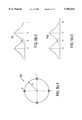
- FIG. 5(a)-5(c) show signal constellations and complex baseband amplitude histograms as used in the variable-modulation-order MPSK demodulators described in the present invention
- FIG. 6 shows one embodiment of a variable-modulation-order MPSK demodulator described in the present invention
- FIG. 7 shows a second embodiment of a variable-modulation-order MPSK demodulator described in the present invention.
- FIG. 8 shows a graphic illustration of a number of MPSK modem performance plots in which bit error rates are plotted against the ratios of signal energy per bit to the noise power spectral density.
- FIG. 2 there is shown a schematic diagram of a communication system which is designated generally by the numeral 100.
- data may be received for transmission by the system 100 from any number of data sources, which may be colocated with the transmit subsystem 110, or located remotely and connected to the transmit subsystem via standard, fixed data links.
- the data sources, and their links with the transmit subsystem 110 are not separately shown.
- a transmit subsystem 110 is depicted to receive data, which may be data messages having a given length, as a data input via a data port (DATA IN) at 112. Any desirable data source or number of data sources may be coupled to the data port 112.
- DATA IN data port
- the physical data port 112 represents typical data input provisions, such as standard telephone connectors, and parallel or serial data connectors, capable of transferring received data to a communication interface and storage module (DATA STORE) 114.
- the data port 112 may represent and include a plurality of connected fixed lines for simultaneously receiving a plurality of messages, even from different origins.
- the data are, consequently received by the transmit subsystem 110 through the data port 112 as input data messages at a determinable average source, or input, data rate. It should be realized that for most practical systems, from a statistical viewpoint, the average input data rate of received messages, averaged over some suitable observation period, such as one hour may be variable with time, such as the time of day.
- the communication interface and storage module 114 includes a typical interface having a corresponding capability of receiving data inputs through one or a plurality data input lines.
- the interface function of the communication interface and storage module 114 includes typical switching circuits with a known capability of receiving a number of messages simultaneously from any such input devices over the data port 112, as may be coupled thereto.
- a storage capacity of the communication interface and storage module 114 comprises typical data storage capacity, such as typical semiconductor memory or magnetic storage.
- a particular type of the communication system 100 is known as a "store-and-forward" communication system.
- received data are not immediately transmitted upon receipt, but instead may remain temporarily stored in memory, such as in the memory of the communication interface and storage module 114, to be further processed into data packets which will ultimately be transmitted.
- Temporary storage also permits momentary traffic loads to be accommodated without causing catastrophic system failures.
- a queue manager and data formatter module (QUEUE MANAGER FORMATTER), hereinafter queue manager 118, is coupled at 116 to the communication interface and storage DATA STORE module 114 to remove received data from the module 114 and format the data into data packets which may then be transmitted.
- the queue manager 118 forwards such data packets, as shown at 120, to a VARIABLE MODULATOR module 122 that is under the control of the SYMBOL RATE/MODULATION CONTROL module 134.
- the variable modulator 122 performs a number of key functions. In addition to modulation, it also performs any forward error correction and symbol framing that may be called for in the communication system architecture. Information about modulation format and symbol rate are provided to module 122 by SYMBOL RATE/MODULATION CONTROL module 134. While it is possible to have variability in the type of modulation itself, such as FSK, PSK and QAM, it is preferable, for demodulation simplicity, to keep the modulation type fixed and vary only the order of the modulation.
- the preferred embodiment uses Nyquist-filtered differential MPSK, where "M” denotes the number of levels, or order, of the modulation. M also denotes the number of allowed phases in the signal constellation. Typical and preferred values of M are 2 n , where n is an integer; that is, n takes on values such as 2 (denoting BPSK), 4 (denoting QPSK) and 8 (denoting 8PSK).
- M denotes the number of levels, or order, of the modulation. M also denotes the number of allowed phases in the signal constellation. Typical and preferred values of M are 2 n , where n is an integer; that is, n takes on values such as 2 (denoting BPSK), 4 (denoting QPSK) and 8 (denoting 8PSK).
- differential modulation coherent modulation may also be used, according to exactly the same methods taught above.
- the difference between differential and direct encoding of phase in MPSK modulation is well known in the art and is not discussed here.
- the output signal, at 124, from the variable modulator 122 is a modulated analog signal which is passed to a variable power transmitter 126.
- the variable power transmitter 126 converts the modulated carrier signal to an RF modulated carrier signal and boosts the power of the RF modulated carrier signal for transmission thereof from a transmit antenna 128 over a communication channel of fixed bandwidth, as shown at 130.
- the above description represents the "upconversion" approach to transmit modulation. It is also possible to implement direct modulation of the RF carrier without departing from the methods taught here, that is, by implementing direct modulation with variable modulation-order and symbol rate.
- variable modulator 122 of modulating data at different rates and modulation formats onto the carrier wave, as described above, is controlled by a digital signal input at 132 from a SYMBOL-RATE/MODULATION CONTROL module 134.
- Module 134 decides on the modulation format and the transmit symbol rate to be used by the variable modulator 122, based on a knowledge of the required transmit data rate, the available modulation formats and the available channel bandwidth. The basis of the selection is described below.
- the channel bandwidth is fixed. Knowledge of this channel bandwidth is either embedded in module 134, or communicated to it by an overall transmit-subsystem management system, which is not shown in FIG. 2 as its functions are not relevant to the main teachings of this invention.
- R c be the selected channel, or transmit, data rate in bits/second.
- R c is selected by module 140 (DATA RATE/TRANSMIT POWER SELECTION) and communicated to module 134 via input 138.
- W be the desired bandpass, or double sided, bandwidth in Hz of the transmit signal. W is upper bounded by the bandpass channel bandwidth B, and is typically less than B by a predetermined guard band.
- X be the excess bandwidth factor, described in the Background, expressed as a fraction less than 1.0.
- X min be the minimum value of X that is allowed by the communication system design, based on the practical realizability of the receive demodulator. For data rates R c less than approximately B/2, it is not necessary to employ modulation orders greater than 2, that is M greater than 2 in MPSK. For any given X min the maximum transmit symbol rate R smax is given by:
- M binary modulation schemes
- the decision to select the next value of M, in the progression described above, is based on comparing (R c /n) with R smax given by equation (3) above. When (R c /n) exceeds R smax , M must be increased to the next higher value.
- module 134 SYMBOL RATE/MODULATION CONTROL
- module 140 DATA RATE/TRANSMIT POWER SELECTION
- the data rate control module 134 therefore preferably controls also the formatting rate of the queue manager 118, as indicated by a data rate input signal 136 to the queue manager 118.
- the selection control module 140 contains some of the key intelligence involved in the adaptive setting of the installed channel capacity.
- the parameters selected by module 140 are a transmit information rate, which is used interchangeably in this description with transmit data rate, and a transmit power.
- the choice of transmit data rate is communicated to SYMBOL RATE/MODULATION CONTROL module 134 via link 138, while the transmit power is communicated to TRANSMIT POWER CONTROL module 144 through link 142.
- the choices of transmit data rate R c and transmit power P T are related, as described below.
- Module 140 contains a stored look-up table of minimum E b /N 0 versus modulation format, as depicted for some cases of MPSK in FIG. 1 and FIG. 8. Using this look-up table, module 140 determines the minimum E b /N 0 required for the selected modulation format. As N 0 is usually quite predictable in satellite communications, being determined primarily by receiver noise figure, the minimum required E b can be estimated by the transmitter from the threshold value of E b /N 0 .
- the receive desired-signal power S at the destination receiver IF output is given by
- the required transmit power is given by
- L is the link propagation loss.
- L is typically known to the transmitter, or can be estimated within certain accuracy bounds. In mobile satellite systems, such accuracy bounds are quite tight.
- MPSK is the preferred embodiment and is used as an example, the control means taught here are not limited to a specific modulation type. Every digital modulation format has a characteristic bit-error-rate (BER) versus E b /N 0 relationship, sometimes referred to as the "modem curve".
- FIG. 8 shows examples of such modem curves. Given a BER performance objective, the minimum E b /N 0 can be read off from the modem curve and entered in the look-up table referred to above.
- the transmit data rate is normally determined by the traffic load but, under exceptional circumstances such as power reserve emergency or high message priority, the transmit data rate can be set by other requirements independent of the user traffic load.
- the operation of the selection control module 140 to select a transmit data rate and a corresponding transmit power setting is based on inputs from a number of status indicators.
- the status indicators preferably include a channel load indicator (CHANNEL LOAD) 150, a message urgency indicator (URGENCY) 152, a power reserve indicator (POWER RESERVE) 154 and a thermal load indicator (THERMAL LOAD) 156.
- the channel load indicator 150 provides the selection control module 140 with a measure of the traffic load to which the transmitter will be subjected. Under normal operation of the transmit subsystem 110, the channel load indicator will be the primary indicator for the selection control module 140 in making determinations as to optimum data rates and corresponding transmit power settings.
- Traffic load is measured by a metric referred to as the average source data rate, which is given by the number of bytes of messages received by module 114 (DATA STORE), from all sources, in a predetermined observation period, for transmission over the radio communication system 100.
- DATA STORE the number of bytes of messages received by module 114
- 10 minutes has been found to be a typical observation period for determining the average source data rate.
- the requirements determining the observation period length are as follows.
- the observation period must be greater than a minimum value such that excessively frequent changes in transmission parameters are avoided.
- the observation period must also be less than a maximum value to (a) ensure good tracking of traffic dynamics and (b) ensure that message storage module 114 does not suffer from memory overflow owing to an excessively rapid increase in traffic.
- the communication interface and storage module 114 provides an advantageous measuring point for traffic loads.
- a preferred way to determine traffic loads is to collect message traffic data, as messages are received via the data port 112 at the communication interface and storage module 114. Data messages are typically preceded by a message header designating the length of the message. An accumulation of the message lengths in bits, over all input messages and over a predetermined observation period, divided by the duration of the observation period in seconds, provides the average source data rate in bits/second, which, as described above, is the preferred metric for traffic load.
- the message urgency indicator 152 indicates a special condition which may require a temporary deviation from the above-described normal operation of the transmit subsystem 110.
- a message of special urgency may have been received by the communication interface and storage module 114.
- the urgency of the message may be indicated by a special, priority identifying code which may be interpreted, for example, by the queue manager 118.
- the queue manager 118 will move the received message of urgency to the head of the queue and signal, via signal line 158 to the message urgency indicator 152, that such a message of special urgency has been received.
- the selection control module 140 When the selection control module 140 detects an urgency condition through the message urgency indicator 152, and the transmit data rate, modulation order and transmit power settings are currently not at maximum settings, the selection control module 140 generates control signals which temporarily increase such settings to maximum operating levels. From the viewpoint of installed channel capacity, the capacity is temporarily increased to the maximum permissible level to transmit the urgent message in the minimum possible time. While the above description corresponds to a binary scenario involving urgent and non-urgent messages, the methods taught here apply equally to scenarios involving a plurality of urgencies, with a plurality greater than two. In such scenarios, three or more urgency levels would exist, ranging from a minimum to a maximum, requiring the use of a corresponding number and levels of installed channel capacities.
- the power reserve indicator 154 is another indicator which may temporarily cause a deviation from normal operations of the transmit subsystem 110, as previously described.
- the power reserve indicator monitors the status of the energy source which powers the transmit subsystem 110.
- the transmit subsystem 110 is part of a fixed base station and operates normally with an unlimited line energy source, power emergencies affecting the entire base station facility may take on proportions in which the additional load of RF transmission power may be insignificant. In such situations, optimizing the RF transmit power is irrelevant.
- the methods described herein are believed applicable to communication systems, such as the system 100, which may be operable under various conditions and circumstances.
- the power reserve indicator 154 is believed to take on significance primarily in remote, unmanned systems in which an emergency may temporarily cause a loss of a provided energy source, to make it necessary to assign priorities to any remaining power. In such case it may be desirable to operate the transmit subsystem 110 on emergency power for emergency transmissions only.
- the selection control module 140 When the power reserve indicator 154 indicates a power reduction emergency, the selection control module 140, by interpreting the emergency signal from the power reserve status indicator 154, generates respective control signals for reducing the data rate and the transmit power to conserve power within the system 100. If the transmit subsystem 110 is a battery operated unit, such as a hand-held or a truck-mounted unit, the power reserve indicator 154 may generate the power conservation signal at any time when the battery voltage drops below a safe operating level.
- the thermal load indicator 156 is a further safety status indicator which monitors a thermal load on the transmit subsystem 110 and generates an emergency signal when the monitored thermal load exceeds a predetermined safe limit, such that, when the current load continues to exist for any extended period, a system failure may result.
- the selection control module 140 generates control signals over signal lines 138 and 142, causing respective reductions in operational symbol rates and modulation order by the SYMBOL RATE/MODULATION CONTROL module 134 and in the transmit power as set by the TRANSMIT POWER CONTROL MODULE 144.
- the described operation of the transmit subsystem 110 is part of a system operation and, for instance, the selection control module 140 and the communication interface and storage module 114 may further be under system control and in communication with other system components or modules which may make up a particular system of choice. Regarding such interaction, the selection control module 140 and the communication interface and storage module 114 may be monitored, and further message traffic via the data port 112 may be stopped, or reduced, during any periods of the discussed special or emergency conditions.
- the transmit subsystem described above involves fully automatic adaptation of transmit data rate, transmit power, symbol rate and modulation order, or level, in response to time varying input traffic and other conditions.
- the enabling means of automatic adaptation are (a) teaching the benefits and demonstrating the feasibility of adapting the installed capacity of a communications channel to a time varying traffic load, and (b) the rules for selecting transmit power, symbol rate and modulation formats to implement such adaptation in a practical, cost effective manner.
- the adaptation of installed capacity may be implemented manually, by human operators performing the functions of data rate, transmit power and modulation order selection, following substantially the same selection rules as taught here. Such manual implementations of the transmit subsystem 110 would be considered within the scope of the present invention.
- Receiving the modulated data transmission signal over the fixed bandwidth channel is a receive subsystem 170 having a receiver 172 which obtains its input from an antenna 171.
- the received RF signals comprise an analog input via signal line 174 to an adaptive demodulator module (ADAPTIVE DEMODULATOR) 176.
- the adaptive demodulator 176 includes a typical analog to digital signal conversion stage which converts the real analog received signals to complex baseband, that is inphase I and quadrature Q, digital signals, and a digital signal processor "DSP" which extracts the transmitted data from the digital signals.
- the adaptive demodulator 176 senses the variable waveform characteristics of symbol rate and modulation format, selected by the transmit subsystem 110.
- the symbol rate may be sensed by one of several prior art symbol synchronizations DSP algorithms based on sensing the rate of phase transitions in an MPSK signal.
- the adaptive demodulator 176 also estimates the modulation format.
- modulation format variations are restricted to variations in M, or modulation order, in filtered MPSK. Two means of estimating M are taught in this invention, as described below.
- the M-value is sensed by amplitude histogram analysis of the I and Q signals.
- I and Q amplitude histograms are constructed by dividing the total amplitude range of the I and Q signals into a predetermined number of amplitude bins and measuring, over a predetermined observation period, the probability of samples of the sampled signal falling in each bin.
- the probability of a signal sample falling in an amplitude bin is the ratio of the number of samples that actually fall in a given amplitude bin, during a given observation period, to the total number of samples in the observation period.
- FIG. 5(a)-(c) show that the amplitude histograms are bell shaped and centered on the projected amplitudes of the signal constellation points on the I and Q axes. The curves are bell shaped owing to the amplitude distribution, or spread, caused by the combination of filtering and additive Gaussian noise. For BPSK, the bell curves are centered on points 516 and 518 in FIG.
- the Q histogram 520 has a bell shaped curve 522 that is somewhat narrower than the corresponding I histogram curves 512 and 514 as the only contributing factor toward the amplitude spread is noise, there being no signal component in curve 522.
- Curve 522 is centered on a projected amplitude of null value as, for BPSK, the signal constellation points are contained solely on the I axis.
- each value of M is associated with a distinct set of I and Q histogram shapes.
- the histograms would be impulse functions at the same locations on the absicca, or amplitude axis, as where the indicated bell-shaped histogram functions are centered, such as 516, 518, etc.
- the indicated histograms are bell shaped, rather than impulse functions, owing to the amplitude spread introduced by filtering and additive noise.
- FIG. 6 shows a block diagram of a variable-modulation-order MPSK demodulator 600 based on the above described means of I and Q histogramming and histogram pattern matching.
- the received I and Q signals are input via lines 602 and 604 to a Amplitude Histogram Generator module 606, which calculates the I and Q histograms, P(I) and P(Q) respectively, as described above.
- P(I) and P(Q) are input via lines 607 and 608 to a Pattern Matcher module 615, wherein P(I) is correlated with one of n I-reference-histograms and P(Q) is correlated with one of n Q-reference histograms.
- the n I-reference-histograms, p i (I), p 2 (I) . . . p n (I) are input to module 615 on lines 610, 612 . . . 614 respectively, whereas the Q-reference-histograms, p i (Q), p 2 (Q) . . . p n (Q) are input to module 615 on lines 616, 618 . . . 620 respectively.
- the output of the Pattern Matcher 615 is the modulation order, which is output on line 622 to a conventional MPSK demodulator 630.
- This demodulator 630 is fed by the same input I and Q signals as feeding the Amplitude Histogram Generator module 606.
- the I and Q signals are input to module 630 via input lines 626 and 628 and sampling pulses necessary for demodulation are input to module 630 via input line 632.
- the output from module 630 is a demodulated data word on line 632.
- the sampling pulses are provided to module 630 by a symbol synchronizer 634 with is also fed by the same input I and Q signals, as feeding modules 606 and 630, via input lines 636 and 638.
- the second type of variable-modulation-order MPSK demodulator taught in this invention involves demodulating the received complex baseband signal with a conventional MPSK demodulator with M set to its highest value, which is 8 in the present embodiment.
- the demodulator attempts to determine, on a symbol-by-symbol basis, the best match between the tip of each received complex vector and a signal constellation point. Referring to FIG. 5(c), this corresponds to determining, on a maximum likelihood basis, which one of the 8 constellation points, 561, 562, 563, 564, 565, 566, 567 or 568 was transmitted. A decision favoring a particular point is considered a "hit" for that point.
- FIG. 7 shows a block diagram of a second means 700 of demodulating variable-modulation-order MPSK signals.
- I and Q signals are input via lines 710 and 720 to a conventional MPSK Demodulator 730, with M set to the highest allowable value, which is 8 in the preferred embodiment.
- M the highest allowable value
- Eight parallel lines, 731, 732, 733 . . . 738, each corresponding to one constellation point, are output from module 730 and input to the Hit Count Averager 740.
- the outputs b 1 -b 8 on lines 731-738 are binary, having a value of 1 if the corresponding constellation point is hit and 0 if it is not hit.
- the Hit Count Averager 740 accumulates the values of each b i over a predetermined length of time, T. At the end of period T, module 740 decides which are valid constellation points based on the accumulated hit count for each b i exceeding a threshold value. The result is further screened by noting that only certain combinations of the 8 constellation points, 561-568, constitute valid sets.
- the outputs of module 740 are also 8 lines, 741, 742, . . . 748, corresponding to the 8 constellation points 561, 562, . . . 568. If a constellation point is deemed valid by module 740, the value on the corresponding output line is set to the binary value of 1; otherwise it is set to the binary value of 0.
- the eight parallel outputs of module 740 comprise a vector [c 1 , c 2 , . . . c M ], which is input to a NPSK Demodulator 750, with N less than or equal to M.
- the value of N, and the particular constellation points to be used, are given by the vector [c 1 , c 2 , . . . c M ].
- the signal inputs to the NPSK Demodulator 750, provided via lines 752 and 754, are the same I and Q signals as input to the MPSK Demodulator 730.
- the output of the NPSK Demodulator 750 is the demodulated data word provided via output line 760.
- variable demodulator 176 cannot determine the symbol rate and modulation format information from an interpretation of the received data as the sought information must be available before data demodulation is possible.
- FIG. 3 is a plot which shows, along its vertical axis, messages processed per hour in an operational satellite communication system, like the referred to communication system 100, in store-and-forward operations.
- the plot covers substantially a ten-day period with complete 24-hour periods beginning with a Tuesday (TU) and ending on a Wednesday (WE) of the following week, as shown along the horizontal axis of the plot. Midnight separating one day from the next is indicated by heavy vertical lines 210 along the horizontal (TIME) axis.
- the vertical axis has a scale which indicates typical system usage in messages per hour. The vertical scale is marked over a range from zero messages per hour to 25,000 messages per hour.
- the plot shows representative peak system traffic (shown at 212) during late morning hours of each plotted week day of 18,000 to 20,000 messages per hour, and representative traffic lows (shown at 214) after midnight of each week day of about seven thousand message per hour.
- FIG. 4 illustrates a primary object of this invention, which is to dynamically match the installed channel capacity to the time varying input traffic load.
- Curve 410 is an artist's illustration, modeled on actual data shown in FIG. 3, of typical diurnal traffic variations, including one non-busy day sandwiched between two busy days. The fact that non-busy days of the week come in pairs is beside the point here.
- the parameter plotted in curve 410 is the average source data rate, in units of bits/second, as described above.
- Channel capacity also has units of bits/second and is a function of the transmit power, modulation format, channel bandwidth, propagation loss and additive noise, as explained in the Background section.
- the aim of transmit power and modulation format adjustments is to dynamically match the installed channel capacity 420 to the average source data rate 410, while allowing for a prudent capacity margin 440.
- Such dynamic tracking of the input traffic with the installed capacity is economically attractive in satellite communication systems based on leased space segment capacity where the lease cost is partially based on the amount of satellite transponder power consumed.
- the horizontal straight line 430 is representative of prior art systems, where the installed capacity is inflexible and based on an estimate of the peak traffic load.
- the values of E b /N 0 required by MPSK at a BER of 10 -3 are shown in the diagram. In practice, 1-2 dB performance margin must be allowed with respect to the curves shown in FIG. 8, which are theoretical, to allow for implementation losses.
Abstract
Description
C=B[1+(S/N)] (1)
E.sub.b /N.sub.0 =[2.sup.(R/B) -1]/[R/B] (2)
R.sub.smax =W/(1+X.sub.min) (3)
S=E.sub.b.R.sub.c (4a)
P.sub.T =S/L (4b)
Claims (1)
Priority Applications (3)
| Application Number | Priority Date | Filing Date | Title |
|---|---|---|---|
| US08/723,406 US5982813A (en) | 1996-09-30 | 1996-09-30 | Demand-based power and data rate adjustments to a transmitter to optimize channel capacity and power usage with respect to data transmission traffic over a fixed-bandwidth channel |
| CA002217357A CA2217357A1 (en) | 1996-09-30 | 1997-09-30 | Demand-based power and data rate adjustments to a transmitter to optimize channel capacity and power usage with respect to data transmission traffic over a fixed-bandwidth channel |
| US11/485,649 USRE40078E1 (en) | 1996-09-30 | 2006-07-13 | Demand-based power and data rate adjustments to a transmitter to optimize channel capacity and power usage with respect to data transmission traffic over a fixed-bandwidth channel |
Applications Claiming Priority (1)
| Application Number | Priority Date | Filing Date | Title |
|---|---|---|---|
| US08/723,406 US5982813A (en) | 1996-09-30 | 1996-09-30 | Demand-based power and data rate adjustments to a transmitter to optimize channel capacity and power usage with respect to data transmission traffic over a fixed-bandwidth channel |
Related Child Applications (1)
| Application Number | Title | Priority Date | Filing Date |
|---|---|---|---|
| US11/485,649 Reissue USRE40078E1 (en) | 1996-09-30 | 2006-07-13 | Demand-based power and data rate adjustments to a transmitter to optimize channel capacity and power usage with respect to data transmission traffic over a fixed-bandwidth channel |
Publications (1)
| Publication Number | Publication Date |
|---|---|
| US5982813A true US5982813A (en) | 1999-11-09 |
Family
ID=24906127
Family Applications (2)
| Application Number | Title | Priority Date | Filing Date |
|---|---|---|---|
| US08/723,406 Ceased US5982813A (en) | 1996-09-30 | 1996-09-30 | Demand-based power and data rate adjustments to a transmitter to optimize channel capacity and power usage with respect to data transmission traffic over a fixed-bandwidth channel |
| US11/485,649 Expired - Lifetime USRE40078E1 (en) | 1996-09-30 | 2006-07-13 | Demand-based power and data rate adjustments to a transmitter to optimize channel capacity and power usage with respect to data transmission traffic over a fixed-bandwidth channel |
Family Applications After (1)
| Application Number | Title | Priority Date | Filing Date |
|---|---|---|---|
| US11/485,649 Expired - Lifetime USRE40078E1 (en) | 1996-09-30 | 2006-07-13 | Demand-based power and data rate adjustments to a transmitter to optimize channel capacity and power usage with respect to data transmission traffic over a fixed-bandwidth channel |
Country Status (2)
| Country | Link |
|---|---|
| US (2) | US5982813A (en) |
| CA (1) | CA2217357A1 (en) |
Cited By (79)
| Publication number | Priority date | Publication date | Assignee | Title |
|---|---|---|---|---|
| US6075821A (en) * | 1997-12-16 | 2000-06-13 | Integrated Telecom Express | Method of configuring and dynamically adapting data and energy parameters in a multi-channel communications system |
| US6084917A (en) * | 1997-12-16 | 2000-07-04 | Integrated Telecom Express | Circuit for configuring and dynamically adapting data and energy parameters in a multi-channel communications system |
| US6084906A (en) * | 1997-12-17 | 2000-07-04 | Integrated Telecom Express | ADSL transceiver implemented with associated bit and energy loading integrated circuit |
| US6094459A (en) * | 1997-12-16 | 2000-07-25 | Integrated Telecom Express | Circuit for configuring data and energy parameters in a multi-channel communications system |
| US6128348A (en) * | 1997-12-16 | 2000-10-03 | Integrated Telecom Express | Method for configuring data and energy parameters in a multi-channel communications system |
| US6169278B1 (en) * | 1999-03-19 | 2001-01-02 | Rockwell Collins, Inc. | Dielectric heating using spread-spectrum energy |
| WO2001010048A1 (en) * | 1999-07-28 | 2001-02-08 | Integrity Broadband Networks, Inc. | Dynamic adaptive modulation negotiation for point-to-point terrestrial links |
| WO2001024389A1 (en) * | 1999-09-27 | 2001-04-05 | Sicom, Inc. | Communication system with end-to-end quadrature balance control |
| WO2001041332A1 (en) * | 1999-12-03 | 2001-06-07 | Telefonaktiebolaget Lm Ericsson (Publ) | Method and system for bit-rate adaptation to improve coverage |
| US6304609B1 (en) * | 1997-05-29 | 2001-10-16 | Trw Inc. | Communication system for broadcasting to mobile users |
| WO2001089099A2 (en) * | 2000-05-12 | 2001-11-22 | Qualcomm Incorporated | A method and an apparatus for improving stability and capacity in cdma medium data rate systems |
| US6330288B1 (en) * | 1999-01-28 | 2001-12-11 | Lucent Technologies Inc. | Coding/modulation scheme selection technique |
| US6359934B1 (en) * | 1998-03-19 | 2002-03-19 | Fujitsu Limited | Adaptive modulation method |
| US20020037061A1 (en) * | 2000-09-20 | 2002-03-28 | Bae Systems Information | System for parameter estimation and tracking of interfering digitally modulated signals |
| US20020037737A1 (en) * | 2000-09-20 | 2002-03-28 | Learned Rachel E. | Method for overusing frequencies to permit simultaneous transmission of signals from two or more users on the same frequency and time slot |
| US20020041566A1 (en) * | 2000-08-11 | 2002-04-11 | Jen-Shun Yang | Dynamic scheduling for packet data network |
| EP0998069A3 (en) * | 1998-10-28 | 2002-09-04 | Inmarsat Ltd. | Communication method and apparatus using a variable modulation scheme |
| US20020126764A1 (en) * | 2000-10-20 | 2002-09-12 | Matsushita Electric Industrial Co., Ltd. | Radio communication apparatus |
| US6452964B1 (en) * | 1998-06-05 | 2002-09-17 | Fujitsu Limited | Adaptive modulation method |
| US20020146030A1 (en) * | 2001-04-06 | 2002-10-10 | Simonsen Harold L. | Multiple access bandwidth-on-demand using MSPK with an embedded tracking channel |
| US20020191706A1 (en) * | 2001-03-22 | 2002-12-19 | Giulio Cavalli | Automatic method for power control and phy mode switching control in adaptive phy mode systems |
| US6501748B1 (en) | 1999-04-21 | 2002-12-31 | Mitsubishi Electric Telecom Europe | Method for balancing the ratio Eb/I in a service multiplexing CDMA system and telecommunication systems using same |
| US6510137B1 (en) * | 1999-08-19 | 2003-01-21 | Mitsubishi Electric Telecom Europe (S.A.) | Method for configuring a telecommunication system |
| US20030026357A1 (en) * | 2001-06-21 | 2003-02-06 | Bartlett Alan M. | Cooperative code-enhanced multi-user communications system |
| US20030026196A1 (en) * | 2001-06-21 | 2003-02-06 | Bae Systems Information And Electronic Systems Integration Inc. | Reduced algorithm receiver |
| US6518893B1 (en) * | 2001-08-24 | 2003-02-11 | Xilinx, Inc. | Method and apparatus for multilevel signal operation |
| US20030054816A1 (en) * | 2001-09-20 | 2003-03-20 | Krebs Lawrence W. | Methods and apparatus for mitigating rain fading over satcom links via information throughput adaptation |
| GB2382956A (en) * | 2001-12-05 | 2003-06-11 | Ipwireless Inc | Method and arrangement for power control |
| US20030148780A1 (en) * | 2002-02-06 | 2003-08-07 | Mitsubishi Denki Kabushiki Kaisha | Transmission power correcting method, mobile communications system and mobile station |
| US20030161280A1 (en) * | 2000-05-30 | 2003-08-28 | Thomas Gruhn | Method for transmitting data packets in a communication system and corresponding transmitter and receiver |
| US20030182369A1 (en) * | 2002-03-25 | 2003-09-25 | Bae Systems Information Electronic Systems Integration, Inc. | System for decreasing processing time in an iterative multi-user detector system |
| US20030187928A1 (en) * | 2002-03-25 | 2003-10-02 | Macleod Robert B. | Frequency mismatch compensation for multiuser detection |
| US20030186703A1 (en) * | 2002-03-29 | 2003-10-02 | International Business Machines Corporation | Bandwidth throttle for a wireless device |
| US20030193966A1 (en) * | 2002-04-11 | 2003-10-16 | Mills Diane G. | Method and apparatus for improved turbo multiuser detector |
| US20030198303A1 (en) * | 2002-04-16 | 2003-10-23 | Taylor Matthew A. | Parameter estimator for a multiuser detection receiver |
| US20030198305A1 (en) * | 2002-03-25 | 2003-10-23 | Taylor Matthew A. | Co-channel interference receiver |
| US20040017863A1 (en) * | 2002-07-29 | 2004-01-29 | Learned Rachel E. | Method and apparatus for optimizing tree pruning in a multiuser detector |
| US6708042B1 (en) * | 1998-07-01 | 2004-03-16 | Matsushita Electric Industrial Co., Ltd. | Communication method and communication system |
| US6724829B1 (en) * | 1999-03-18 | 2004-04-20 | Conexant Systems, Inc. | Automatic power control in a data transmission system |
| WO2004040794A2 (en) * | 2002-10-29 | 2004-05-13 | Qualcomm Incorporated | Controlling multiple modems in a wireless terminal using energy-per-bit determinations |
| US6748206B1 (en) * | 1998-06-23 | 2004-06-08 | Nec Corporation | Low-power-consumption radio receiver |
| US20040174833A1 (en) * | 1998-11-20 | 2004-09-09 | Raith Alex Krister | Thermal transmission control of wireless data modem |
| US20040193971A1 (en) * | 2003-02-14 | 2004-09-30 | Soong Anthony C.K. | Power control for reverse packet data channel in CDMA systems |
| WO2004086668A1 (en) * | 2003-03-28 | 2004-10-07 | Socovar, S.E.C. | Wireless link with adaptive modulation and different qualities of service |
| US20040202067A1 (en) * | 2003-01-08 | 2004-10-14 | Pate Michael A | Mechanism to aid optical beam focusing on optical disc |
| US20040234007A1 (en) * | 2002-01-23 | 2004-11-25 | Bae Systems Information And Electronic Systems Integration Inc. | Multiuser detection with targeted error correction coding |
| US20040246930A1 (en) * | 2003-03-06 | 2004-12-09 | Nortel Networks Limited | Communicating a broadcast message to change data rates of mobile stations |
| US6839390B2 (en) | 2002-01-23 | 2005-01-04 | Bae Systems Information And Electronic Systems Integration Inc. | Voting system for improving the performance of single-user decoders within an iterative multi-user detection system |
| US20050031054A1 (en) * | 2003-08-07 | 2005-02-10 | Kabushiki Kaisha Toshiba | Digital communication device and digital communication system |
| US20050036437A1 (en) * | 2002-08-26 | 2005-02-17 | Learned Rachel E | Multitrack readback and multiuser detection for disk drives |
| US20050122231A1 (en) * | 2003-12-08 | 2005-06-09 | The Regents Of The University Of California | Power efficient wireless system for sensor network |
| US6981203B2 (en) | 2002-04-29 | 2005-12-27 | Bae Systems Information And Electronic Systems Integration Inc. | Method and apparatus for random shuffled turbo multiuser detector |
| US7020081B1 (en) * | 1998-07-10 | 2006-03-28 | Matsushita Electric Industrial Co., Ltd. | Stream distribution system |
| US20060121418A1 (en) * | 2004-12-02 | 2006-06-08 | Lockheed Martin Corporation | System for predictively managing communication attributes of unmanned vehicles |
| US20060221923A1 (en) * | 2005-03-29 | 2006-10-05 | Ntt Docomo | Transmission rate control method, mobile station, radio base station, and radio network controller |
| US20070036250A1 (en) * | 2005-08-10 | 2007-02-15 | Bae Systems Information And Electronic Systems Integration Inc. | M-algorithm multiuser detector with correlation based pruning |
| US7286607B1 (en) | 2002-12-31 | 2007-10-23 | United States Of America As Represented By The Secretary Of The Navy | Energy-control method and apparatus for digital diversity signaling |
| US7301904B1 (en) * | 2002-06-28 | 2007-11-27 | Nortel Networks Limited | System and method for maximizing throughput in a telecommunications system |
| US20070281001A1 (en) * | 2006-05-31 | 2007-12-06 | Herman Douglas | Cat in heat cool formula™ |
| US20080095290A1 (en) * | 2004-09-01 | 2008-04-24 | Leung Tak M | Method And Apparatus For Identifying The Modulation Format Of A Received Signal |
| US7403781B2 (en) * | 1998-10-06 | 2008-07-22 | Siemens Aktiengesellschaft | Method and apparatus for adapting data rates for services over a connection between a base station and a subscriber station |
| US20080253389A1 (en) * | 2004-10-15 | 2008-10-16 | Peter Larsson | Method and System of Radio Communications With Various Resolution Levels of Signal Modulation Depending on Propagation Conditions |
| CN100455113C (en) * | 2005-08-18 | 2009-01-21 | 华为技术有限公司 | Up-link access method for user terminal |
| US7737841B2 (en) | 2006-07-14 | 2010-06-15 | Remotemdx | Alarm and alarm management system for remote tracking devices |
| US7804412B2 (en) | 2005-08-10 | 2010-09-28 | Securealert, Inc. | Remote tracking and communication device |
| US7869822B2 (en) * | 2003-02-24 | 2011-01-11 | Autocell Laboratories, Inc. | Wireless network apparatus and system field of the invention |
| US20110064064A1 (en) * | 2002-12-19 | 2011-03-17 | Research In Motion Limited | Wireless/lan router queuing method and system |
| US7936262B2 (en) | 2006-07-14 | 2011-05-03 | Securealert, Inc. | Remote tracking system with a dedicated monitoring center |
| US20110255467A1 (en) * | 2008-02-07 | 2011-10-20 | Peter Larsson | Method and system of radio communications with various resolution levels of signal modulation depending on propagation conditions |
| US20120170594A1 (en) * | 2011-10-13 | 2012-07-05 | Comtech Ef Data Corp. | Method and System for Optimizing Data Throughput Performance for Dynamic Link Conditions Using Adaptive Coding and Modulation (ACM) and Dynamic Single Channel per Carrier (dSCPC) Techniques |
| US8232876B2 (en) | 2008-03-07 | 2012-07-31 | Securealert, Inc. | System and method for monitoring individuals using a beacon and intelligent remote tracking device |
| US20130138830A1 (en) * | 2011-11-28 | 2013-05-30 | Huawei Technologies Co., Ltd. | Method and network device for controlling transmission rate of communication interface |
| US8494063B1 (en) * | 2001-09-25 | 2013-07-23 | Netgear, Inc. | System and method for stacking receiver channels for increased system through-put in an RF data transmission system |
| US8514070B2 (en) | 2010-04-07 | 2013-08-20 | Securealert, Inc. | Tracking device incorporating enhanced security mounting strap |
| US8797210B2 (en) | 2006-07-14 | 2014-08-05 | Securealert, Inc. | Remote tracking device and a system and method for two-way voice communication between the device and a monitoring center |
| US20140302891A1 (en) * | 2009-04-13 | 2014-10-09 | Huawei Technologies Co., Ltd. | Method, device, and system for regulating power consumption |
| US9185604B2 (en) * | 2001-02-23 | 2015-11-10 | Ipr Licensing, Inc. | Qualifying available reverse link coding rates from access channel power setting |
| US20210028861A1 (en) * | 2013-12-18 | 2021-01-28 | Northrop Grumman Systems Corporation | Optical transceiver with variable data rate and sensitivity control |
| US11915578B2 (en) * | 2021-12-20 | 2024-02-27 | Jvckenwood Corporation | Beacon device, positioning system, beacon signal transmission method |
Families Citing this family (2)
| Publication number | Priority date | Publication date | Assignee | Title |
|---|---|---|---|---|
| US10601521B2 (en) | 2018-05-14 | 2020-03-24 | Nokia Solutions And Networks Oy | Coherent optical communication with constellations having coordinates on circles |
| US11309972B2 (en) | 2019-09-20 | 2022-04-19 | Nokia Solutions And Networks Oy | Optical communication system employing a multidimensional constellation with an increased minimum distance |
Citations (5)
| Publication number | Priority date | Publication date | Assignee | Title |
|---|---|---|---|---|
| US5115429A (en) * | 1990-08-02 | 1992-05-19 | Codex Corporation | Dynamic encoding rate control minimizes traffic congestion in a packet network |
| US5452009A (en) * | 1993-12-29 | 1995-09-19 | Zenith Electronics Corp. | Digital transmission system with data rate optimized for noise in transmission medium |
| US5463656A (en) * | 1993-10-29 | 1995-10-31 | Harris Corporation | System for conducting video communications over satellite communication link with aircraft having physically compact, effectively conformal, phased array antenna |
| US5471497A (en) * | 1993-11-01 | 1995-11-28 | Zehavi; Ephraim | Method and apparatus for variable rate signal transmission in a spread spectrum communication system using coset coding |
| US5475711A (en) * | 1992-10-30 | 1995-12-12 | At&T Corp. | System for channel capacity modulation |
Family Cites Families (1)
| Publication number | Priority date | Publication date | Assignee | Title |
|---|---|---|---|---|
| US5630212A (en) * | 1994-03-28 | 1997-05-13 | P-Com, Inc. | Microwave radio system with software configuration of operating parameters |
-
1996
- 1996-09-30 US US08/723,406 patent/US5982813A/en not_active Ceased
-
1997
- 1997-09-30 CA CA002217357A patent/CA2217357A1/en not_active Abandoned
-
2006
- 2006-07-13 US US11/485,649 patent/USRE40078E1/en not_active Expired - Lifetime
Patent Citations (5)
| Publication number | Priority date | Publication date | Assignee | Title |
|---|---|---|---|---|
| US5115429A (en) * | 1990-08-02 | 1992-05-19 | Codex Corporation | Dynamic encoding rate control minimizes traffic congestion in a packet network |
| US5475711A (en) * | 1992-10-30 | 1995-12-12 | At&T Corp. | System for channel capacity modulation |
| US5463656A (en) * | 1993-10-29 | 1995-10-31 | Harris Corporation | System for conducting video communications over satellite communication link with aircraft having physically compact, effectively conformal, phased array antenna |
| US5471497A (en) * | 1993-11-01 | 1995-11-28 | Zehavi; Ephraim | Method and apparatus for variable rate signal transmission in a spread spectrum communication system using coset coding |
| US5452009A (en) * | 1993-12-29 | 1995-09-19 | Zenith Electronics Corp. | Digital transmission system with data rate optimized for noise in transmission medium |
Cited By (189)
| Publication number | Priority date | Publication date | Assignee | Title |
|---|---|---|---|---|
| US6304609B1 (en) * | 1997-05-29 | 2001-10-16 | Trw Inc. | Communication system for broadcasting to mobile users |
| US6084917A (en) * | 1997-12-16 | 2000-07-04 | Integrated Telecom Express | Circuit for configuring and dynamically adapting data and energy parameters in a multi-channel communications system |
| US6094459A (en) * | 1997-12-16 | 2000-07-25 | Integrated Telecom Express | Circuit for configuring data and energy parameters in a multi-channel communications system |
| US6128348A (en) * | 1997-12-16 | 2000-10-03 | Integrated Telecom Express | Method for configuring data and energy parameters in a multi-channel communications system |
| US6075821A (en) * | 1997-12-16 | 2000-06-13 | Integrated Telecom Express | Method of configuring and dynamically adapting data and energy parameters in a multi-channel communications system |
| US6222888B1 (en) | 1997-12-16 | 2001-04-24 | Integrated Telecom Express, Inc. | Method and circuit for controlling setup of multichannel system |
| US6292515B1 (en) | 1997-12-16 | 2001-09-18 | Integrated Telecom Express, Inc. | Dual mode bit and gain loading circuit and process |
| US6084906A (en) * | 1997-12-17 | 2000-07-04 | Integrated Telecom Express | ADSL transceiver implemented with associated bit and energy loading integrated circuit |
| US6359934B1 (en) * | 1998-03-19 | 2002-03-19 | Fujitsu Limited | Adaptive modulation method |
| US6452964B1 (en) * | 1998-06-05 | 2002-09-17 | Fujitsu Limited | Adaptive modulation method |
| US20090003302A1 (en) * | 1998-06-10 | 2009-01-01 | Siemens Aktiengesellschaft | Method for adapting data rates |
| US6748206B1 (en) * | 1998-06-23 | 2004-06-08 | Nec Corporation | Low-power-consumption radio receiver |
| US6708042B1 (en) * | 1998-07-01 | 2004-03-16 | Matsushita Electric Industrial Co., Ltd. | Communication method and communication system |
| US7020081B1 (en) * | 1998-07-10 | 2006-03-28 | Matsushita Electric Industrial Co., Ltd. | Stream distribution system |
| US7403781B2 (en) * | 1998-10-06 | 2008-07-22 | Siemens Aktiengesellschaft | Method and apparatus for adapting data rates for services over a connection between a base station and a subscriber station |
| US8989168B2 (en) | 1998-10-06 | 2015-03-24 | Siemens Aktiengesellschaft | Method for adapting data rates |
| EP1381180A1 (en) * | 1998-10-28 | 2004-01-14 | Inmarsat Ltd. | Communication method and apparatus using a variable modulation scheme |
| EP0998069A3 (en) * | 1998-10-28 | 2002-09-04 | Inmarsat Ltd. | Communication method and apparatus using a variable modulation scheme |
| US20040174833A1 (en) * | 1998-11-20 | 2004-09-09 | Raith Alex Krister | Thermal transmission control of wireless data modem |
| US7860018B2 (en) * | 1998-11-20 | 2010-12-28 | Ericsson Inc. | Thermal transmission control of wireless data modem |
| US6330288B1 (en) * | 1999-01-28 | 2001-12-11 | Lucent Technologies Inc. | Coding/modulation scheme selection technique |
| US6724829B1 (en) * | 1999-03-18 | 2004-04-20 | Conexant Systems, Inc. | Automatic power control in a data transmission system |
| US6169278B1 (en) * | 1999-03-19 | 2001-01-02 | Rockwell Collins, Inc. | Dielectric heating using spread-spectrum energy |
| US20080056203A1 (en) * | 1999-04-21 | 2008-03-06 | Mitsubishi Electric Corporation | Method for balancing the ratio eb/i in a service multiplexing cdma system and telecommunication systems using same |
| US20040165673A1 (en) * | 1999-04-21 | 2004-08-26 | Vincent Belaiche | Method for balancing the ratio EB/I in a service multiplexing CDMA system and telecommunication systems using method |
| US7027422B2 (en) | 1999-04-21 | 2006-04-11 | Melco Mobile Communications Europe | Method for balancing the ratio Eb/l in a service multiplexing CDMA system and telecommunication system using this method |
| US20080056204A1 (en) * | 1999-04-21 | 2008-03-06 | Mitsubishi Electric Corporation | Method for balancing the ratio eb/i in a service multiplexing cdma system and telecommunication systems using same |
| US6501748B1 (en) | 1999-04-21 | 2002-12-31 | Mitsubishi Electric Telecom Europe | Method for balancing the ratio Eb/I in a service multiplexing CDMA system and telecommunication systems using same |
| US7995540B2 (en) | 1999-04-21 | 2011-08-09 | Misubishi Electric Corporation | Method for balancing the ratio Eb/I in a service multiplexing CDMA system and telecommunication systems using same |
| US8094626B2 (en) | 1999-04-21 | 2012-01-10 | Mitsubishi Electric Corporation | Method for a code division multiple access telecommunication system |
| US8787179B2 (en) | 1999-04-21 | 2014-07-22 | Mitsubishi Electric Corporation | Method for a telecommunication system, a telecommunication system, a base station for communicating and a communication method of a base station having a plurality of transport channels and using a first parameter relating to a rate matching ratio and a second parameter corresponding to a maximum percentage of bits punctured |
| US20080056309A1 (en) * | 1999-04-21 | 2008-03-06 | Mitsubishi Electric Corporation | Method for balancing the ratio eb/i in a service multiplexing cdma system and telecommunication systems using same |
| US9584257B2 (en) | 1999-04-21 | 2017-02-28 | Mitsubishi Electric Corporation | Method for balancing the ratio Eb/I in a service multiplexing CDMA system and telecommunication systems using same |
| US6545983B2 (en) | 1999-04-21 | 2003-04-08 | Mitsubishi Electric Telecom Europe | Method for balancing the ratio Eb/I in a service multiplexing CDMA system and telecommunication systems using same |
| US20060251117A1 (en) * | 1999-04-21 | 2006-11-09 | Mitsubishi Electric Telecom Europe | Method for balancing the ratio Eb/I in a service multiplexing CDMA system and telecommunication systems using same |
| US8787322B2 (en) | 1999-04-21 | 2014-07-22 | Mitsubishi Electric Corporation | Method for a telecommunication system having a plurality of transport channels that transforms at least one data block size based on a rate matching ratio and a maximum percentage of bits to be punctured |
| US20080056310A1 (en) * | 1999-04-21 | 2008-03-06 | Mitsubishi Electric Corporation | Method for balancing the ratio eb/i in a service multiplexing cdma system and telecommunication systems using same |
| US9401777B2 (en) | 1999-04-21 | 2016-07-26 | Mitsubishi Electric Corporation | Communication apparatus for communicating data conveyed by a plurality of transport channels |
| US7133388B2 (en) | 1999-04-21 | 2006-11-07 | Melco Mobile Communications Europe | Method for balancing the ratio EB/I in a service multiplexing CDMA system and telecommunication systems using same |
| US6330278B1 (en) * | 1999-07-28 | 2001-12-11 | Integrity Broadband Networks, Inc. | Dynamic adaptive modulation negotiation for point-to-point terrestrial links |
| WO2001010048A1 (en) * | 1999-07-28 | 2001-02-08 | Integrity Broadband Networks, Inc. | Dynamic adaptive modulation negotiation for point-to-point terrestrial links |
| US20020101913A1 (en) * | 1999-07-28 | 2002-08-01 | Masters Jeffrey Tony | Dynamic adaptive modulation negotiation for point-to-point terrestrial links |
| US20050259582A1 (en) * | 1999-08-19 | 2005-11-24 | Melco Mobile Communications Europe (Sa) | Method for configuring a telecommunication system |
| US8467292B2 (en) | 1999-08-19 | 2013-06-18 | Research In Motion Limited | Method for configuring a telecommunication system |
| US9225465B2 (en) | 1999-08-19 | 2015-12-29 | Blackberry Limited | Method for configuring a telecommunication system |
| US7855964B2 (en) | 1999-08-19 | 2010-12-21 | Mitsubishi Electric Corporation | Communication method and apparatus and base station |
| US6510137B1 (en) * | 1999-08-19 | 2003-01-21 | Mitsubishi Electric Telecom Europe (S.A.) | Method for configuring a telecommunication system |
| US7773518B2 (en) | 1999-08-19 | 2010-08-10 | Mitsubishi Electric Corporation | Method for configuring a telecommunication system |
| US8111621B2 (en) | 1999-08-19 | 2012-02-07 | Research In Motion Limited | Method for configuring a telecommunication system |
| US8116198B2 (en) | 1999-08-19 | 2012-02-14 | Research In Motion Limited | Method for configuring a telecommunication system |
| US20080144646A1 (en) * | 1999-08-19 | 2008-06-19 | Mitsubishi Electric Corporation | Method for configuring a telecommunication system |
| US20060083190A1 (en) * | 1999-08-19 | 2006-04-20 | Melco Mobile Communications Europe (Sa) | Method for configuring a telecommunication system |
| US20030067905A1 (en) * | 1999-08-19 | 2003-04-10 | Mitsubishi Electric Telecom Europe | Method for configuring a telecommunication system |
| US20080144492A1 (en) * | 1999-08-19 | 2008-06-19 | Mitsubishi Electric Corporation | Method for configuring a telecommunication system |
| US7864680B2 (en) | 1999-08-19 | 2011-01-04 | Mitsubishi Electric Corporation | Communication apparatus and method |
| US7012894B2 (en) * | 1999-08-19 | 2006-03-14 | Melco Mobile Communications Europe | Method for configuring a telecommunication system |
| US20080144592A1 (en) * | 1999-08-19 | 2008-06-19 | Mitsubishi Electric Corporation | Method for configuring a telecommunication system |
| US8483060B2 (en) | 1999-08-19 | 2013-07-09 | Research In Motion Limited | Method for configuring a telecommunication system |
| US6222878B1 (en) * | 1999-09-27 | 2001-04-24 | Sicom, Inc. | Communication system with end-to-end quadrature balance control |
| WO2001024389A1 (en) * | 1999-09-27 | 2001-04-05 | Sicom, Inc. | Communication system with end-to-end quadrature balance control |
| WO2001041332A1 (en) * | 1999-12-03 | 2001-06-07 | Telefonaktiebolaget Lm Ericsson (Publ) | Method and system for bit-rate adaptation to improve coverage |
| WO2001089099A3 (en) * | 2000-05-12 | 2002-07-18 | Qualcomm Inc | A method and an apparatus for improving stability and capacity in cdma medium data rate systems |
| WO2001089099A2 (en) * | 2000-05-12 | 2001-11-22 | Qualcomm Incorporated | A method and an apparatus for improving stability and capacity in cdma medium data rate systems |
| KR100854201B1 (en) | 2000-05-12 | 2008-08-26 | 콸콤 인코포레이티드 | A method and an apparatus for improving stability and capacity in cdma medium data rate systems |
| US7369499B2 (en) * | 2000-05-30 | 2008-05-06 | Siemens Aktiengesellschaft | Method for transmitting data packets in a communication system and corresponding transmitter and receiver |
| US20030161280A1 (en) * | 2000-05-30 | 2003-08-28 | Thomas Gruhn | Method for transmitting data packets in a communication system and corresponding transmitter and receiver |
| US20020041566A1 (en) * | 2000-08-11 | 2002-04-11 | Jen-Shun Yang | Dynamic scheduling for packet data network |
| US6996061B2 (en) * | 2000-08-11 | 2006-02-07 | Industrial Technology Research Institute | Dynamic scheduling for packet data network |
| US20020037061A1 (en) * | 2000-09-20 | 2002-03-28 | Bae Systems Information | System for parameter estimation and tracking of interfering digitally modulated signals |
| US6947505B2 (en) | 2000-09-20 | 2005-09-20 | Bae Systems Information And Electronic Systems Integration Inc. | System for parameter estimation and tracking of interfering digitally modulated signals |
| US20020037737A1 (en) * | 2000-09-20 | 2002-03-28 | Learned Rachel E. | Method for overusing frequencies to permit simultaneous transmission of signals from two or more users on the same frequency and time slot |
| US7058422B2 (en) | 2000-09-20 | 2006-06-06 | Bae Systems Information And Electronic Systems Integration Inc. | Method for overusing frequencies to permit simultaneous transmission of signals from two or more users on the same frequency and time slot |
| US7023933B2 (en) * | 2000-10-20 | 2006-04-04 | Matsushita Electric Industrial Co., Ltd. | Radio communication apparatus |
| US20110200086A1 (en) * | 2000-10-20 | 2011-08-18 | Panasonic Corporation | Radio communication apparatus capable of switching modulation schemes |
| US9590834B2 (en) | 2000-10-20 | 2017-03-07 | Wi-Fi One, Llc | Radio communication apparatus capable of switching modulation schemes |
| US7953177B2 (en) | 2000-10-20 | 2011-05-31 | Panasonic Corporation | Radio communication apparatus capable of switching modulation schemes |
| US20020126764A1 (en) * | 2000-10-20 | 2002-09-12 | Matsushita Electric Industrial Co., Ltd. | Radio communication apparatus |
| US8218680B2 (en) | 2000-10-20 | 2012-07-10 | Panasonic Corporation | Radio communication apparatus capable of switching modulation schemes |
| US7738590B2 (en) | 2000-10-20 | 2010-06-15 | Panasonic Corporation | Radio communication apparatus capable of switching modulation schemes |
| US20100266059A1 (en) * | 2000-10-20 | 2010-10-21 | Panasonic Corporation | Radio communication apparatus capable of switching modulation schemes |
| US20060136975A1 (en) * | 2000-10-20 | 2006-06-22 | Matsushita Electric Industrial Co., Ltd. | Radio communication apparatus |
| US10638468B2 (en) | 2001-02-23 | 2020-04-28 | Ipr Licensing, Inc. | Qualifying available reverse link coding rates from access channel power setting |
| US9497761B2 (en) | 2001-02-23 | 2016-11-15 | Ipr Licensing, Inc. | Qualifying available reverse link coding rates from access channel power setting |
| US9185604B2 (en) * | 2001-02-23 | 2015-11-10 | Ipr Licensing, Inc. | Qualifying available reverse link coding rates from access channel power setting |
| US9913271B2 (en) | 2001-02-23 | 2018-03-06 | Ipr Licensing, Inc. | Qualifying available reverse link coding rates from access channel power setting |
| US7092453B2 (en) * | 2001-03-22 | 2006-08-15 | Siemens Information And Communication Networks S.P.A. | Automatic method for power control and phy mode switching control in adaptive phy mode systems |
| US20020191706A1 (en) * | 2001-03-22 | 2002-12-19 | Giulio Cavalli | Automatic method for power control and phy mode switching control in adaptive phy mode systems |
| US7133395B2 (en) * | 2001-04-06 | 2006-11-07 | L-3 Communications Corporation | Multiple access bandwidth-on-demand using MSPK with an embedded tracking channel |
| US20020146030A1 (en) * | 2001-04-06 | 2002-10-10 | Simonsen Harold L. | Multiple access bandwidth-on-demand using MSPK with an embedded tracking channel |
| US7200103B2 (en) | 2001-06-21 | 2007-04-03 | Bae Systems Information And Electronic Systems Integration Inc. | Reduced algorithm receiver |
| US20030026357A1 (en) * | 2001-06-21 | 2003-02-06 | Bartlett Alan M. | Cooperative code-enhanced multi-user communications system |
| US20030026196A1 (en) * | 2001-06-21 | 2003-02-06 | Bae Systems Information And Electronic Systems Integration Inc. | Reduced algorithm receiver |
| US7139334B2 (en) | 2001-06-21 | 2006-11-21 | Bartlett Alan M | Cooperative code-enhanced multi-user communications system |
| US6518893B1 (en) * | 2001-08-24 | 2003-02-11 | Xilinx, Inc. | Method and apparatus for multilevel signal operation |
| US20030054816A1 (en) * | 2001-09-20 | 2003-03-20 | Krebs Lawrence W. | Methods and apparatus for mitigating rain fading over satcom links via information throughput adaptation |
| US7174179B2 (en) | 2001-09-20 | 2007-02-06 | Itt Manufacturing Enterprises, Inc. | Methods and apparatus for mitigating rain fading over SATCOM links via information throughput adaptation |
| US8494063B1 (en) * | 2001-09-25 | 2013-07-23 | Netgear, Inc. | System and method for stacking receiver channels for increased system through-put in an RF data transmission system |
| US9730192B1 (en) | 2001-09-25 | 2017-08-08 | Netgear, Inc. | System and method for stacking receiver channels for increased system through-put in an RF data transmission system |
| US10070423B2 (en) | 2001-09-25 | 2018-09-04 | Netgear, Inc. | System and method for stacking receiver channels for increased system through-put in an RF data transmission system |
| US20040043783A1 (en) * | 2001-12-05 | 2004-03-04 | Ipwireless, Inc. | Method and arrangement for power control |
| US20080207251A1 (en) * | 2001-12-05 | 2008-08-28 | Nicholas William Anderson | Method and arrangement for power control |
| GB2382956A (en) * | 2001-12-05 | 2003-06-11 | Ipwireless Inc | Method and arrangement for power control |
| GB2382956B (en) * | 2001-12-05 | 2006-03-01 | Ipwireless Inc | Method and arrangement for power control |
| US8521212B2 (en) | 2001-12-05 | 2013-08-27 | Sony Corporation | Method and arrangement for power control |
| US7373161B2 (en) * | 2001-12-05 | 2008-05-13 | Ipwireless, Inc. | Method and arrangement for power control |
| US8351975B2 (en) | 2001-12-05 | 2013-01-08 | Sony Corporation | Method and arrangement for power control |
| US8060127B2 (en) | 2001-12-05 | 2011-11-15 | Sony Corporation | Method and arrangement for power control |
| US7092464B2 (en) * | 2002-01-23 | 2006-08-15 | Bae Systems Information And Electronic Systems Integration Inc. | Multiuser detection with targeted error correction coding |
| US6839390B2 (en) | 2002-01-23 | 2005-01-04 | Bae Systems Information And Electronic Systems Integration Inc. | Voting system for improving the performance of single-user decoders within an iterative multi-user detection system |
| US20040234007A1 (en) * | 2002-01-23 | 2004-11-25 | Bae Systems Information And Electronic Systems Integration Inc. | Multiuser detection with targeted error correction coding |
| EP1592146A3 (en) * | 2002-02-06 | 2006-01-04 | Mitsubishi Denki Kabushiki Kaisha | Transmission power correcting method, mobile communications system and mobile station |
| US20030148780A1 (en) * | 2002-02-06 | 2003-08-07 | Mitsubishi Denki Kabushiki Kaisha | Transmission power correcting method, mobile communications system and mobile station |
| EP1592145A2 (en) * | 2002-02-06 | 2005-11-02 | Mitsubishi Denki Kabushiki Kaisha | Transmission power control method, mobile communications system and mobile station |
| EP1339175A2 (en) * | 2002-02-06 | 2003-08-27 | Mitsubishi Denki Kabushiki Kaisha | Transmission power control method, mobile communications system and mobile station |
| US6934556B2 (en) | 2002-02-06 | 2005-08-23 | Mitsubishi Denki Kabushiki Kaisha | Transmission power correcting method, mobile communications system and mobile station |
| EP1592146A2 (en) * | 2002-02-06 | 2005-11-02 | Mitsubishi Denki Kabushiki Kaisha | Transmission power correcting method, mobile communications system and mobile station |
| EP1339175A3 (en) * | 2002-02-06 | 2004-01-07 | Mitsubishi Denki Kabushiki Kaisha | Transmission power control method, mobile communications system and mobile station |
| EP1592145A3 (en) * | 2002-02-06 | 2006-01-04 | Mitsubishi Denki Kabushiki Kaisha | Transmission power control method, mobile communications system and mobile station |
| US20050153726A1 (en) * | 2002-02-06 | 2005-07-14 | Mitsubishi Denki Kabushiki Kaisha | Transmission power correcting method, mobile communications system and mobile station |
| US7190747B2 (en) | 2002-03-25 | 2007-03-13 | Bae Systems Information And Electronic Systems Integration Inc. | Frequency mismatch compensation for multiuser detection |
| US20030198305A1 (en) * | 2002-03-25 | 2003-10-23 | Taylor Matthew A. | Co-channel interference receiver |
| US7092452B2 (en) | 2002-03-25 | 2006-08-15 | Bae Systems Information And Electronic Systems Integration Inc | Co-channel interference receiver |
| US20030182369A1 (en) * | 2002-03-25 | 2003-09-25 | Bae Systems Information Electronic Systems Integration, Inc. | System for decreasing processing time in an iterative multi-user detector system |
| US20030187928A1 (en) * | 2002-03-25 | 2003-10-02 | Macleod Robert B. | Frequency mismatch compensation for multiuser detection |
| US7110439B2 (en) | 2002-03-25 | 2006-09-19 | Bae Systems Information And Electronic Systems Integration Inc. | System for decreasing processing time in an iterative multi-user detector system |
| US7085289B2 (en) * | 2002-03-29 | 2006-08-01 | International Business Machines Corporation | Bandwidth throttle for a wireless device |
| US20030186703A1 (en) * | 2002-03-29 | 2003-10-02 | International Business Machines Corporation | Bandwidth throttle for a wireless device |
| US20030193966A1 (en) * | 2002-04-11 | 2003-10-16 | Mills Diane G. | Method and apparatus for improved turbo multiuser detector |
| US6947506B2 (en) | 2002-04-11 | 2005-09-20 | Bae Systems Information And Electronic Systems Integration Inc. | Method and apparatus for improved turbo multiuser detector |
| US6947502B2 (en) | 2002-04-16 | 2005-09-20 | Taylor Matthew A | Parameter estimator for a multiuser detection receiver |
| US20030198303A1 (en) * | 2002-04-16 | 2003-10-23 | Taylor Matthew A. | Parameter estimator for a multiuser detection receiver |
| US6981203B2 (en) | 2002-04-29 | 2005-12-27 | Bae Systems Information And Electronic Systems Integration Inc. | Method and apparatus for random shuffled turbo multiuser detector |
| US7301904B1 (en) * | 2002-06-28 | 2007-11-27 | Nortel Networks Limited | System and method for maximizing throughput in a telecommunications system |
| US20040017863A1 (en) * | 2002-07-29 | 2004-01-29 | Learned Rachel E. | Method and apparatus for optimizing tree pruning in a multiuser detector |
| US7190743B2 (en) | 2002-07-29 | 2007-03-13 | Bae Systems Information And Electronic Systems Integration Inc. | Method and apparatus for optimizing tree pruning in a multiuser detector |
| US20050036437A1 (en) * | 2002-08-26 | 2005-02-17 | Learned Rachel E | Multitrack readback and multiuser detection for disk drives |
| US7126890B2 (en) | 2002-08-26 | 2006-10-24 | Bae Systems Information And Electronic Systems Integration Inc | Multitrack readback and multiuser detection for disk drives |
| US20040198406A1 (en) * | 2002-10-29 | 2004-10-07 | Aziz Gholmieh | Controlling multiple modems in a wireless terminal using energy-per-bit determinations |
| WO2004040794A2 (en) * | 2002-10-29 | 2004-05-13 | Qualcomm Incorporated | Controlling multiple modems in a wireless terminal using energy-per-bit determinations |
| US20060003792A1 (en) * | 2002-10-29 | 2006-01-05 | Aziz Gholmieh | Controlling multiple modems in a wireless terminal using energy-per-bit determinations |
| US7020484B2 (en) | 2002-10-29 | 2006-03-28 | Qualcomm Incorporated | Controlling multiple modems in a wireless terminal using energy-per-bit determinations |
| WO2004040794A3 (en) * | 2002-10-29 | 2004-12-23 | Qualcomm Inc | Controlling multiple modems in a wireless terminal using energy-per-bit determinations |
| US20140036896A1 (en) * | 2002-12-19 | 2014-02-06 | Blackberry Limited | Wireless/lan router queuing method and system |
| US8989200B2 (en) * | 2002-12-19 | 2015-03-24 | Blackberry Limited | Wireless/LAN router queuing method and system |
| US8576860B2 (en) * | 2002-12-19 | 2013-11-05 | Blackberry Limited | Wireless/LAN router queuing method and system |
| US20110064064A1 (en) * | 2002-12-19 | 2011-03-17 | Research In Motion Limited | Wireless/lan router queuing method and system |
| US7286607B1 (en) | 2002-12-31 | 2007-10-23 | United States Of America As Represented By The Secretary Of The Navy | Energy-control method and apparatus for digital diversity signaling |
| US20040202067A1 (en) * | 2003-01-08 | 2004-10-14 | Pate Michael A | Mechanism to aid optical beam focusing on optical disc |
| US7299402B2 (en) * | 2003-02-14 | 2007-11-20 | Telefonaktiebolaget Lm Ericsson (Publ) | Power control for reverse packet data channel in CDMA systems |
| US20040193971A1 (en) * | 2003-02-14 | 2004-09-30 | Soong Anthony C.K. | Power control for reverse packet data channel in CDMA systems |
| US7869822B2 (en) * | 2003-02-24 | 2011-01-11 | Autocell Laboratories, Inc. | Wireless network apparatus and system field of the invention |
| US8254358B2 (en) | 2003-03-06 | 2012-08-28 | Ericsson Ab | Communicating a broadcast message to change data rates of mobile stations |
| US9319920B2 (en) | 2003-03-06 | 2016-04-19 | Ericsson Ab | Communicating a broadcast message to change data rates of mobile stations |
| US20040246930A1 (en) * | 2003-03-06 | 2004-12-09 | Nortel Networks Limited | Communicating a broadcast message to change data rates of mobile stations |
| WO2004086668A1 (en) * | 2003-03-28 | 2004-10-07 | Socovar, S.E.C. | Wireless link with adaptive modulation and different qualities of service |
| US20050031054A1 (en) * | 2003-08-07 | 2005-02-10 | Kabushiki Kaisha Toshiba | Digital communication device and digital communication system |
| US20050122231A1 (en) * | 2003-12-08 | 2005-06-09 | The Regents Of The University Of California | Power efficient wireless system for sensor network |
| US7738413B2 (en) * | 2003-12-08 | 2010-06-15 | The Regents Of The University Of California | Minimizing power consumption in a wireless system for a sensor networks using time slots for nodes |
| US20080095290A1 (en) * | 2004-09-01 | 2008-04-24 | Leung Tak M | Method And Apparatus For Identifying The Modulation Format Of A Received Signal |
| US20080253389A1 (en) * | 2004-10-15 | 2008-10-16 | Peter Larsson | Method and System of Radio Communications With Various Resolution Levels of Signal Modulation Depending on Propagation Conditions |
| US20060121418A1 (en) * | 2004-12-02 | 2006-06-08 | Lockheed Martin Corporation | System for predictively managing communication attributes of unmanned vehicles |
| US9383750B2 (en) | 2004-12-02 | 2016-07-05 | Lockheed Martin Corporation | System for predictively managing communication attributes of unmanned vehicles |
| US20060221923A1 (en) * | 2005-03-29 | 2006-10-05 | Ntt Docomo | Transmission rate control method, mobile station, radio base station, and radio network controller |
| US7817597B2 (en) * | 2005-03-29 | 2010-10-19 | Ntt Docomo, Inc. | Transmission rate control method, mobile station, radio base station, and radio network controller |
| US8031077B2 (en) | 2005-08-10 | 2011-10-04 | Securealert, Inc. | Remote tracking and communication device |
| US20070036250A1 (en) * | 2005-08-10 | 2007-02-15 | Bae Systems Information And Electronic Systems Integration Inc. | M-algorithm multiuser detector with correlation based pruning |
| US7613228B2 (en) | 2005-08-10 | 2009-11-03 | Bae Systems Information And Electronic Systems Integration Inc. | M-Algorithm multiuser detector with correlation based pruning |
| US7804412B2 (en) | 2005-08-10 | 2010-09-28 | Securealert, Inc. | Remote tracking and communication device |
| CN100455113C (en) * | 2005-08-18 | 2009-01-21 | 华为技术有限公司 | Up-link access method for user terminal |
| US20070281001A1 (en) * | 2006-05-31 | 2007-12-06 | Herman Douglas | Cat in heat cool formula™ |
| US8013736B2 (en) | 2006-07-14 | 2011-09-06 | Securealert, Inc. | Alarm and alarm management system for remote tracking devices |
| US7737841B2 (en) | 2006-07-14 | 2010-06-15 | Remotemdx | Alarm and alarm management system for remote tracking devices |
| US7936262B2 (en) | 2006-07-14 | 2011-05-03 | Securealert, Inc. | Remote tracking system with a dedicated monitoring center |
| US8797210B2 (en) | 2006-07-14 | 2014-08-05 | Securealert, Inc. | Remote tracking device and a system and method for two-way voice communication between the device and a monitoring center |
| US20110255467A1 (en) * | 2008-02-07 | 2011-10-20 | Peter Larsson | Method and system of radio communications with various resolution levels of signal modulation depending on propagation conditions |
| US8232876B2 (en) | 2008-03-07 | 2012-07-31 | Securealert, Inc. | System and method for monitoring individuals using a beacon and intelligent remote tracking device |
| US20160255582A1 (en) * | 2009-04-13 | 2016-09-01 | Huawei Technologies Co., Ltd. | Method, device, and system for regulating power consumption |
| US9369955B2 (en) * | 2009-04-13 | 2016-06-14 | Huawei Technologies Co., Ltd. | Method, device, and system for regulating power consumption |
| US9699724B2 (en) * | 2009-04-13 | 2017-07-04 | Huawei Technologies Co., Ltd. | Method, device, and system for regulating power consumption |
| US20140302891A1 (en) * | 2009-04-13 | 2014-10-09 | Huawei Technologies Co., Ltd. | Method, device, and system for regulating power consumption |
| US9129504B2 (en) | 2010-04-07 | 2015-09-08 | Securealert, Inc. | Tracking device incorporating cuff with cut resistant materials |
| US8514070B2 (en) | 2010-04-07 | 2013-08-20 | Securealert, Inc. | Tracking device incorporating enhanced security mounting strap |
| US20120170594A1 (en) * | 2011-10-13 | 2012-07-05 | Comtech Ef Data Corp. | Method and System for Optimizing Data Throughput Performance for Dynamic Link Conditions Using Adaptive Coding and Modulation (ACM) and Dynamic Single Channel per Carrier (dSCPC) Techniques |
| US9025516B2 (en) * | 2011-10-13 | 2015-05-05 | Comtech Ef Data Corp. | Method and system for optimizing data throughput performance for dynamic link conditions using adaptive coding and modulation (ACM) and dynamic single channel per carrier (dSCPC) techniques |
| US20130138830A1 (en) * | 2011-11-28 | 2013-05-30 | Huawei Technologies Co., Ltd. | Method and network device for controlling transmission rate of communication interface |
| US8667167B2 (en) * | 2011-11-28 | 2014-03-04 | Huawei Technologies Co., Ltd. | Method and network device for controlling transmission rate of communication interface |
| US20210028861A1 (en) * | 2013-12-18 | 2021-01-28 | Northrop Grumman Systems Corporation | Optical transceiver with variable data rate and sensitivity control |
| US11601197B2 (en) * | 2013-12-18 | 2023-03-07 | Northrop Grumman Systems Corporation | Optical transceiver with variable data rate and sensitivity control |
| US11915578B2 (en) * | 2021-12-20 | 2024-02-27 | Jvckenwood Corporation | Beacon device, positioning system, beacon signal transmission method |
Also Published As
| Publication number | Publication date |
|---|---|
| USRE40078E1 (en) | 2008-02-19 |
| CA2217357A1 (en) | 1998-03-30 |
Similar Documents
| Publication | Publication Date | Title |
|---|---|---|
| US5982813A (en) | Demand-based power and data rate adjustments to a transmitter to optimize channel capacity and power usage with respect to data transmission traffic over a fixed-bandwidth channel | |
| EP0963074B1 (en) | Estimation of constellation size for adaptive modulation system | |
| US20020061073A1 (en) | Apparatus and method for controlling wireless communication signals | |
| US5764699A (en) | Method and apparatus for providing adaptive modulation in a radio communication system | |
| CN100414856C (en) | Radio communication method and radio communication apparatus using adaptive modulation system | |
| US6404755B1 (en) | Multi-level information mapping system and method | |
| US7873124B2 (en) | Method for digital wireless communications | |
| US20050099992A1 (en) | Data communication control system, transmitter, and transmitting method | |
| EP2288066A2 (en) | Method and apparatus for maintaining a predefined transmission quality in a wireless MAN network | |
| NO325908B1 (en) | Optimal utilization of the available capacity of a communication system | |
| CN103068022A (en) | Communication device, transmission power determination method and program | |
| US7577100B2 (en) | System and method for measuring signal to noise values in an adaptive wireless communication system | |
| WO2000076109A1 (en) | System and method for adaptive modulation in a cellular telecommunications network | |
| EP1037437A2 (en) | Modulation method and system for unbalanced quadrature phase shift keying | |
| EP1706973B1 (en) | Method of signalling, a communication system and a communication equipment | |
| Umebayashi et al. | Blind adaptive estimation of modulation scheme for software defined radio | |
| US7095797B2 (en) | Method of modulating a data signal with modulation switching between direct and differential modulation and apparatus for modulation | |
| US10797921B2 (en) | Threshold computation circuit for S-FSK receiver, integrated circuit, and method associated therewith | |
| WO2004086668A1 (en) | Wireless link with adaptive modulation and different qualities of service | |
| JP5472448B2 (en) | COMMUNICATION DEVICE, COMMUNICATION SYSTEM, AND COMMUNICATION CONTROL METHOD | |
| JP4177879B1 (en) | Reception device, transmission device, and wireless communication system | |
| Selmi et al. | Optimum joint adaptive modulation and coding and power control for packet transmission over fading channels using the ARQ protocol | |
| EP1244227A1 (en) | Automatic method for power control and phy mode switching control in adaptive phy mode systems | |
| Komaki | Theoretical analyses of a capacity controlled digital microwave radio transmission | |
| Sajadieh et al. | Analysis of two-layered adaptive transmission systems |
Legal Events
| Date | Code | Title | Description |
|---|---|---|---|
| AS | Assignment |
Owner name: ROCKWELL INTERNATIONAL CORPORATION, IOWA Free format text: ASSIGNMENT OF ASSIGNORS INTEREST;ASSIGNORS:DUTTA, SANTANU;MAHANY, RICHARD J.;REEL/FRAME:008195/0369 Effective date: 19960930 |
|
| AS | Assignment |
Owner name: ROCKWELL COLLINS, INC., IOWA Free format text: ASSIGNMENT OF ASSIGNORS INTEREST;ASSIGNOR:ROCKWELL INTERNATIONAL CORPORATION;REEL/FRAME:008359/0886 Effective date: 19970214 |
|
| AS | Assignment |
Owner name: AMSC SUBSIDIARY CORPORATION, VIRGINIA Free format text: ASSIGNMENT OF ASSIGNOR'S INTEREST. RE-RECORD TO CORRECT THE RECORDATION DATE OF 02-24-97 TO 02-21-97, PREVIOUSLY RECORDED AT REEL 8402, FRAME 0238.;ASSIGNOR:ROCKWELL COLLINS, INC.;REEL/FRAME:008408/0237 Effective date: 19970220 Owner name: AMSC SUBSIDIARY CORPORATION, VIRGINIA Free format text: ;ASSIGNOR:ROCKWELL COLLINS, INC.;REEL/FRAME:008402/0238 Effective date: 19970220 |
|
| AS | Assignment |
Owner name: AMSC SUBSIDIARY CORPORATION, VIRGINIA Free format text: ASSIGNMENT OF ASSIGNORS INTEREST;ASSIGNOR:ROCKWELL COLLINS, INC.;REEL/FRAME:008374/0323 Effective date: 19970220 |
|
| AS | Assignment |
Owner name: ROCKWELL COLLINS, INC., IOWA Free format text: ASSIGNMENT OF ASSIGNORS INTEREST;ASSIGNOR:ROCKWELL INTERNATIONAL CORPORATION;REEL/FRAME:010132/0213 Effective date: 19970214 Owner name: ROCKWELL INTERNATIONAL CORPORATION, IOWA Free format text: ASSIGNMENT OF ASSIGNORS INTEREST;ASSIGNORS:DUTTA, SANTANU;MAHANY, RICHARD J.;REEL/FRAME:010132/0346 Effective date: 19960930 Owner name: AMSC SUBSIDIARY CORPORATION, VIRGINIA Free format text: ASSIGNMENT OF ASSIGNORS INTEREST;ASSIGNOR:ROCKWELL COLLINS, INC.;REEL/FRAME:010132/0165 Effective date: 19961122 |
|
| STCF | Information on status: patent grant |
Free format text: PATENTED CASE |
|
| AS | Assignment |
Owner name: MOTIENT SERVICES INC., VIRGINIA Free format text: CHANGE OF NAME;ASSIGNOR:AMSC SUBSIDIARY CORPORATION;REEL/FRAME:011369/0235 Effective date: 20000424 |
|
| AS | Assignment |
Owner name: MOBILE SATELLITE VENTURES LP, VIRGINIA Free format text: ASSIGNMENT OF ASSIGNORS INTEREST;ASSIGNOR:MOTIENT SERVICES, INC.;REEL/FRAME:012785/0731 Effective date: 20020308 Owner name: MOBILE SATELLITE VENTURES LP, VIRGINIA Free format text: ASSIGNMENT OF ASSIGNORS INTEREST;ASSIGNOR:MOTIENT SERVICES INC.;REEL/FRAME:012791/0347 Effective date: 20020308 |
|
| FPAY | Fee payment |
Year of fee payment: 4 |
|
| AS | Assignment |
Owner name: ATC TECHNOLOGIES, LLC,VIRGINIA Free format text: ASSIGNMENT OF ASSIGNORS INTEREST;ASSIGNOR:MOBILE SATELLITE VENTURES, LP;REEL/FRAME:016357/0374 Effective date: 20050616 Owner name: ATC TECHNOLOGIES, LLC, VIRGINIA Free format text: ASSIGNMENT OF ASSIGNORS INTEREST;ASSIGNOR:MOBILE SATELLITE VENTURES, LP;REEL/FRAME:016357/0374 Effective date: 20050616 |
|
| AS | Assignment |
Owner name: THE BANK OF NEW YORK,NEW YORK Free format text: SECURITY AGREEMENT;ASSIGNORS:ATC TECHNOLOGIES, LLC;MOBILE SATELLITE VENTURES LP;REEL/FRAME:017435/0603 Effective date: 20060330 Owner name: THE BANK OF NEW YORK, NEW YORK Free format text: SECURITY AGREEMENT;ASSIGNORS:ATC TECHNOLOGIES, LLC;MOBILE SATELLITE VENTURES LP;REEL/FRAME:017435/0603 Effective date: 20060330 |
|
| RF | Reissue application filed |
Effective date: 20060713 |
|
| FPAY | Fee payment |
Year of fee payment: 8 |
|
| AS | Assignment |
Owner name: ATC TECHNOLOGIES, LLC, VIRGINIA Free format text: RELEASE BY SECURED PARTY;ASSIGNOR:THE BANK OF NEW YORK MELLON AS COLLATERAL AGENT;REEL/FRAME:025105/0605 Effective date: 20011001 Owner name: LIGHTSQUARED FINANCE CO., VIRGINIA Free format text: RELEASE BY SECURED PARTY;ASSIGNOR:THE BANK OF NEW YORK MELLON AS COLLATERAL AGENT;REEL/FRAME:025105/0605 Effective date: 20011001 Owner name: LIGHTSQUARED LP, VIRGINIA Free format text: RELEASE BY SECURED PARTY;ASSIGNOR:THE BANK OF NEW YORK MELLON AS COLLATERAL AGENT;REEL/FRAME:025105/0605 Effective date: 20011001 |
|
| AS | Assignment |
Owner name: WILMINGTON TRUST FSB, AS COLLATERAL TRUSTEE, MARYL Free format text: SECURITY AGREEMENT;ASSIGNOR:ATC TECHNOLOGIES, LLC;REEL/FRAME:025126/0120 Effective date: 20101001 |
|
| AS | Assignment |
Owner name: WILMINGTON TRUST FSB, AS COLLATERAL TRUSTEE, DELAW Free format text: SECURITY AGREEMENT;ASSIGNORS:LIGHTSQUARED LP;ATC TECHNOLOGIES, LLC;LIGHTSQUARED INC. OF VIRGINIA;AND OTHERS;REEL/FRAME:026438/0603 Effective date: 20110603 |
|
| AS | Assignment |
Owner name: CREDIT SUISSE AG, CAYMAN ISLANDS BRANCH, NEW YORK Free format text: SECURITY AGREEMENT (FIRST LIEN);ASSIGNOR:ATC TECHNOLOGIES, LLC;REEL/FRAME:037573/0939 Effective date: 20151207 Owner name: JEFFERIES FINANCE LLC, NEW YORK Free format text: SECURITY AGREEMENT (SECOND LIEN);ASSIGNOR:ATC TECHNOLOGIES, LLC;REEL/FRAME:037573/0963 Effective date: 20151207 |
|
| FEPP | Fee payment procedure |
Free format text: PAYER NUMBER DE-ASSIGNED (ORIGINAL EVENT CODE: RMPN); ENTITY STATUS OF PATENT OWNER: LARGE ENTITY Free format text: PAYOR NUMBER ASSIGNED (ORIGINAL EVENT CODE: ASPN); ENTITY STATUS OF PATENT OWNER: LARGE ENTITY |
|
| AS | Assignment |
Owner name: ATC TECHNOLOGIES, LLC, ILLINOIS Free format text: RELEASE BY SECURED PARTY;ASSIGNOR:JEFFERIES FINANCE LLC;REEL/FRAME:054297/0444 Effective date: 20201023 |