US5961099A - Safety net system for debris and mud slides - Google Patents
Safety net system for debris and mud slides Download PDFInfo
- Publication number
- US5961099A US5961099A US09/012,781 US1278198A US5961099A US 5961099 A US5961099 A US 5961099A US 1278198 A US1278198 A US 1278198A US 5961099 A US5961099 A US 5961099A
- Authority
- US
- United States
- Prior art keywords
- columns
- safety net
- net system
- disposed
- rope
- Prior art date
- Legal status (The legal status is an assumption and is not a legal conclusion. Google has not performed a legal analysis and makes no representation as to the accuracy of the status listed.)
- Expired - Fee Related
Links
Images


Classifications
-
- E—FIXED CONSTRUCTIONS
- E01—CONSTRUCTION OF ROADS, RAILWAYS, OR BRIDGES
- E01F—ADDITIONAL WORK, SUCH AS EQUIPPING ROADS OR THE CONSTRUCTION OF PLATFORMS, HELICOPTER LANDING STAGES, SIGNS, SNOW FENCES, OR THE LIKE
- E01F7/00—Devices affording protection against snow, sand drifts, side-wind effects, snowslides, avalanches or falling rocks; Anti-dazzle arrangements ; Sight-screens for roads, e.g. to mask accident site
- E01F7/04—Devices affording protection against snowslides, avalanches or falling rocks, e.g. avalanche preventing structures, galleries
Definitions
- the present invention relates to a safety net system that is placed upright on the ground for restraining debris slides, such as mud slides.
- a number of barriers for restraining falling rocks are known.
- a flexible barrier is disclosed that is provided with posts that pivot on a ground-anchored base plate, with the posts being held by wind bracing cables, some of which extend in an upstream direction and others of which extend in a downstream direction.
- An arresting net is secured to a series of spaced-apart horizontal ropes that are supported by the upstream wind bracing cable.
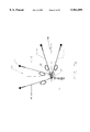
- FIG. 1 illustrates one exemplary embodiment of the inventive safety net system
- FIG. 2 is an end view of the system of FIG. 1;
- FIG. 3 is a detailed view of one of the net panels of the system of FIG. 1, and also illustrates how adjacent net panels are seamed together;
- FIG. 4 is a detailed view showing one exemplary embodiment for anchoring a column of the inventive safety net system
- FIGS. 5a, 5b, 6a, and 6b show the various bracing cables and anchor means for the columns of the inventive safety net system
- FIG. 7 is a detailed view of the brake element or load-absorbing means of the inventive safety net system.
- FIGS. 8-10 show various embodiments and layers of a net panel of the inventive safety net system.
- the safety net system of the present invention includes at least one unit, each of which comprises at least one net panel.
- Each net panel is disposed between two columns that are disposed in or on the ground.
- Each net panel, which is not secured to the columns, is rather secured to top and bottom ropes, and in particular to a continuous top rope that extends from the bottom end of an end column of one of the units, through guide means at the top of that end column, through respective guide means of any intermediate or interposed columns, through guide means at the top of the other end column of that unit, to a bottom end of the other end column of that unit;
- the bottom rope is a continuous rope that extends from the bottom end of one of the end columns, through respective guide means near the bottom ends of any interposed columns, to the bottom end of the other end column of the unit.
- Anchor means are disposed both laterally of each end column, and uphill of each of the columns, wherein bracing cables that extend from both the upper and bottom ends of each of the end columns extend to the lateral anchor means, and further bracing cables extend from both the upper and bottom ends of each of the columns to the uphill anchor means.
- FIG. 1 shows one exemplary embodiment of the inventive safety net system, which is indicated generally by the reference numeral 20.
- the safety net system 20 is shown as being comprised of two units 22, each of which includes several net panels 23, which will be described in detail subsequently.
- each unit 22 is anchored in a very specific manner, as will also be described in detail subsequently.
- each unit 22, which comprises at least one net panel 23, which is preferably a woven net panel, will now be described in conjunction with some of the more detailed figures.
- FIG. 2 illustrates an end net panel 23 of a unit 22 of the inventive safety net system 20
- FIG. 3 shows an intermediate net panel 23 of one exemplary embodiment of the inventive safety net system 20.
- the drawings show how the safety net system is placed upright on the ground or bedrock 24.
- FIG. 2 an enlarged end view of the second or downhill-facing side is shown.
- the net panel 23 is disposed between two columns 25, for example structural steel columns, which are disposed upright at least indirectly in the ground or bedrock 24.
- the net panel 23 is held in place in a manner to be described in detail subsequently.
- a top rope 27 extends continuously from near the bottom of one end column 25, where it is secured in a convenient manner, all the way to the bottom of the other end column 25 of a given unit 22 of the safety net system 20.
- a bottom rope 28 extends continuously from the bottom of one of the end columns 25 of a given unit 22 to the other end column 25 thereof.
- the continuous top rope 27 extends from the bottom of a given end column 25, where it is secured, then to the top of that column, where it extends through a guide means 29, then extends along the top of the unit 22 through respective guide means at the top of any interposed or intermediate columns 25, then extends through the guide means 29 of the other end column 25, and finally extends to the bottom end of this other end column 25, where it is also secured (see FIGS. 2 and 3).
- the continuous bottom rope 28, extends from the bottom end of one of the end columns 25, where it is secured, through respective guide means 30 provided near the bottom ends of any interposed columns 25, to the bottom end of the other end column 25 of the unit 22, where it is also secured.
- the columns 25 are preferably profiled, having for example an H-shaped cross-sectional configuration.
- the columns themselves are disposed on or in the ground in a number of different ways.
- the column 25 can be connected to a base plate 32, which is then secured directly to anchor bolts 33 that are disposed in the ground 24, or can be bolted to a further base plate 34 that is itself secured in the ground by the anchor bolts 33.
- anchor bolts can either be disposed directly in the ground or bedrock 24, or can be secured in poured concrete 35, as illustrated in FIG. 3. It would also be possible to dispose the column 25 in a hole that is then filled with concrete. Any other convenient manner for disposing the columns 25 on or in the ground could, of course, also be utilized.
- the columns 25 are furthermore supported by various ropes, especially wire ropes, as well as anchor means, which are all collectively referred to as bracing means.
- the end columns 25 are braced by lateral bracing means 37, which absorb the major force.
- all of the columns 25 are braced by uphill bracing means 38.
- Each of the lateral bracing means 37 comprises a rope or bracing cable 40 that extends from the top of an end column 25 to the anchor means 41.
- the bracing cable 40 can be secured to the top of the column 25 in any convenient manner, for example to the guide means 29 or to any other convenient securing means.
- a further rope or bracing cable 42 extends from the bottom of the end column 25, where it is secured in any convenient manner to the anchor means 41.
- the uphill bracing means 38 comprises a rope or bracing cable 44 that extends from the top of a respective column 25 to an anchor means 45.
- a rope or bracing cable 46 extends from the bottom of each of the columns 25 to the anchor means 45.
- the lateral bracing means 37 comprises two sets of top and bottom bracing cables 40, 42, and the uphill bracing means 38 also comprises two sets of top and bottom bracing cables 44, 46.
- the lateral bracing means 37 are disposed only at the end columns 25, whereas the uphill bracing means 38 are disposed on all of the columns 25.
- the lateral bracing means 37 can be disposed within 15° of a plane that extends parallel to the plane of the adjacent net panel 23, it would be possible to provide only a single top bracing cable 40 and bottom bracing cable 42, as shown for example in FIG. 2.
- the uphill bracing means 38 can be disposed within 15° of a plane extending perpendicular to the plane formed by the net panels 23 that adjoin the pertaining column 25, it would be possible to provide only a single top bracing cable 44 and bottom bracing cable 46.
- bracing cables could either extend within 15° or less of the respective plane, but in any case should preferably extend at an angle of no greater than 45° relative to the pertaining plane. At angles greater than 15° two sets of bracing cables are preferred in order to absorb bending moments in the columns 25.
- anchor means 41 and 45 Possible constructions for the anchor means 41 and 45 will now be described in conjunction with FIG. 2, which illustrates the lateral anchor means 41.
- anchor means can comprise a wire rope anchor that together with a preferably splayed end is anchored in concrete poured into a hole in the ground 24.
- the anchor means 41 also has a loop end; the ends of the top and bottom bracing cables 40, 42 are looped through the preferably reinforced loop end of the anchor means 41 and are then connected to themselves, for example by wire rope clips, with four such clips 48 being illustrated in FIG. 2.
- the anchor means 41 could be a solid steel type anchor, which is advantageously used in easy-to-drill ground.
- the load-absorbing means 50 are disposed in particular on the top rope 27 and the bottom rope 28. As can be seen in FIGS. 1-3, four such load-absorbing means are associated with each of the net panels 23, and should be disposed within three feet of the center line of the adjacent column 25. In addition, it is expedient to provide such load-absorbing means on both the top and bottom bracing cables 44, 46 of the uphill bracing means 38. Load-absorbing means 50 can also be provided on the top and bottom bracing cables 40, 42 of the lateral bracing means 37.
- the load-absorbing means 50 can, for example, be in the form of a friction brake or dampening means, and as shown in FIG. 7 comprises a tube 51, for example a one inch ID galvanized tube, that is formed in an open loop or ring, with overlapping ends 54.
- a rope or cable 52 such as the top or bottom ropes 27, 28, or one of the bracing cables 40, 42, 44 or 46, is passed through the tube or ring 51b
- the ends 54 of the tubular ring 51 are then clamped together by means of a clamp or stop sleeve 53, which can be press-fitted on the tube and provide frictional engagement of the tube with the rope or cable 52.
- the load-absorbing means 50 disposed along the top and bottom ropes 27, 28 allow the net panels 23 to absorb the impact of mud and debris.
- the net panels 23 can bulge or deflect with the aid of the load-absorbing means 50, which operate by having the tube 51 decrease in diameter when a predetermined kinetic load is applied to the pertaining top or bottom rope 27, 28.
- the load-absorbing means 50 in the bracing cables 44, 46 of the uphill bracing means 38 dampen the force that might otherwise cause the columns 25 to shear off, for example by shearing of the bolt 55 that is disposed at the base of the column 25 (see FIG. 4).
- Load-absorbing means 50 in the bracing cables 40, 42 of the lateral bracing means 37 help to keep the columns 25 from being pulled inwardly toward one another when the safety net system 20 is restraining a mud and debris slide.
- the columns 25 are preferably a break-away assembly, for example by means of the aforementioned shearing bolt 55.
- the net panels 23 are secured to the top and bottom ropes 27, 28 by seam ropes 57 only, i.e. without the use of clips that restrict movement (see in particular FIGS. 2 and 3).
- the ends of the seam ropes 57 are clipped together by wire rope clips 58.
- adjacent net panels 23 are seamed together by the seam ropes 57 that secure the net panels 23 to the top and bottom ropes 27, 28. It should be noted that the net panels 23 are never seamed to the columns 25, with the seam ropes 57 therefore being disposed on only one side of the column, namely the downhill side of the safety net system 20.
- each of the net panels 23 comprises a woven netting, for example a woven 8 inch by 8 inch diagonal weave mesh netting made from a single wire rope having only a single joint, as indicated by the reference numeral 60 in FIG. 8.
- This joint 60 can, for example, be in the form of a stop sleeve.
- other forms of netting are also possible, such as the ring net 62 shown in FIG. 9, wherein the rings have, by way of example only, a diameter of twelve inches and are made of a 3/8 or 1/2 inch cable, or a diameter of sixteen inches and are made of a 3/4 inch cable.
- the rings have, by way of example only, a diameter of twelve inches and are made of a 3/8 or 1/2 inch cable, or a diameter of sixteen inches and are made of a 3/4 inch cable.
- the wire rope 64 can, in one specific embodiment of the present invention, have a diameter of 5/16 of an inch.
- intersecting portions of the wire rope 64 are secured to one another by clips, for example the cross clips 65 indicated in FIG. 8.
- the netting is then clipped to a border rope 66, for example via C-clamps 67; the border rope can, for example, have a diameter of 5/8 of an inch.
- the thus completed net panel 23 is then seamed to the top and bottom ropes 27, 28 by the seam ropes 57, which as indicated also seam a given net panel 23 to an adjacent net panel if one is present.
- the seam ropes 57 engage only other wire ropes, such as the border rope 66 and the top and bottom ropes 27, 28, and do not seam the net panels 23 to the columns 25.
- top and bottom ropes 27, 28, as well as the seam ropes 57 and the border rope 66, are preferably wire ropes.
- the top and bottom ropes 27, 28 can be of 3/4 inch diameter, while the seam ropes 57 can have a diameter of 5/16 of an inch.
- the net panels 23 also have a layered configuration, as shown in FIG. 3.
- a chain link fencing 70 such as an eleven gauge galvanized chain link, also known as a railing fabric, having a diagonal configuration and a mesh size of 1 inch by 1 inch (see FIG. 10).
- the chain link fencing 70 is secured to the wire rope netting, for example by hog rings.
- This smaller mesh chain link fencing 70 not only helps to retain smaller material, but also aids in better distributing the impact load to the wire rope netting of the panels 23.
- a silt screen fabric such a very fine-meshed plastic fabric, or chicken wire, on the first or uphill side of the chain link railing fabric 70; such an optional silt fabric 71 is illustrated in FIG. 3.
- each unit 22 of the inventive safety net system 20 comprises at least one net panel 23; a typical length of such a net panel could be 20 feet, with a typical height of such a net panel 23, which can also vary depending upon need, being, for example, 10 feet.
- Each unit 22 can also comprise a plurality of net panels 23, whereby a given unit 22 preferably has a length of no greater than 100 feet.
- Several abutting units 22 can also be provided. In such a case, the adjacent units 22 could have their facing end net panels 23 abut one another, and could even share a common column 25 (see FIG. 1). In such a situation, the adjacent end panels 23 could be seamed together via the seamed ropes 57, as previously discussed in conjunction with adjacent net panels 23 as illustrated in FIGS.
- the lateral bracing means 37 of each of the units 22 overlaps the end net panel 23 of the adjacent unit 22.
- the anchor means 41 for the bracing cables 40, 42 of the lateral bracing means 37 can be anchored in the ground 24 in several ways.
- the anchor means 41 can share a hole with the column 25 that is disposed at the far left end of the overlapped end net panel 23 of the adjacent unit 22, and is imbedded in the same concrete as is this column 25 or the anchor means 41 thereof.
- the anchor means 41 is preferably anchored in concrete provided in a separate hole.
Abstract
Description
Claims (20)
Priority Applications (2)
| Application Number | Priority Date | Filing Date | Title |
|---|---|---|---|
| US09/012,781 US5961099A (en) | 1998-01-23 | 1998-01-23 | Safety net system for debris and mud slides |
| CA002260331A CA2260331C (en) | 1998-01-23 | 1999-01-25 | Safety net system for debris and mud slides |
Applications Claiming Priority (1)
| Application Number | Priority Date | Filing Date | Title |
|---|---|---|---|
| US09/012,781 US5961099A (en) | 1998-01-23 | 1998-01-23 | Safety net system for debris and mud slides |
Publications (1)
| Publication Number | Publication Date |
|---|---|
| US5961099A true US5961099A (en) | 1999-10-05 |
Family
ID=21756663
Family Applications (1)
| Application Number | Title | Priority Date | Filing Date |
|---|---|---|---|
| US09/012,781 Expired - Fee Related US5961099A (en) | 1998-01-23 | 1998-01-23 | Safety net system for debris and mud slides |
Country Status (2)
| Country | Link |
|---|---|
| US (1) | US5961099A (en) |
| CA (1) | CA2260331C (en) |
Cited By (62)
| Publication number | Priority date | Publication date | Assignee | Title |
|---|---|---|---|---|
| US6581875B2 (en) * | 2001-10-12 | 2003-06-24 | Engineered Arresting Systems Corporation | Anchoring systems for aircraft arresting nets |
| US6592103B2 (en) * | 2000-11-13 | 2003-07-15 | Fatzer Ag | Catchment net for rockfall catchment systems or the like |
| EP1362621A1 (en) * | 2002-05-15 | 2003-11-19 | Adic Promotion S.A. | Safety device through energy absorption, composed of rods and nets aimed at stopping skiers falling at high speed |
| US6698142B2 (en) * | 2000-11-03 | 2004-03-02 | Sinco, Inc. | Netting system for use with bleachers and grandstands |
| EP1462573A2 (en) | 2003-03-22 | 2004-09-29 | Andreas Herold | Device for protecting against falling rocks |
| US20040217341A1 (en) * | 2003-05-01 | 2004-11-04 | Gumb Tyler T. | Jack fence |
| US20050029408A1 (en) * | 2003-08-04 | 2005-02-10 | Mauro Giuseppin | Wire ring net for rocky wall barriers and method for making it |
| US20050050830A1 (en) * | 2003-09-10 | 2005-03-10 | Marcel Sennhauser | Catchment net, especially for rockfall blocking |
| US20050104054A1 (en) * | 2003-11-19 | 2005-05-19 | Cyro Industries, A Company Of The State Of New Jersey | Traffic noise barrier system |
| AU781578B2 (en) * | 2000-11-13 | 2005-06-02 | Fatzer Ag | Catchment net for rockfall catchment systems or the like |
| US20050230187A1 (en) * | 2004-04-16 | 2005-10-20 | Bradley Gayle M | Driveway safety net and method |
| US20060140718A1 (en) * | 2004-12-29 | 2006-06-29 | Lamore Michael J | Retractable wide-span vehicle barrier system |
| US20060140717A1 (en) * | 2004-12-29 | 2006-06-29 | Lamore Michael J | Retractable wide-span vehicle barrier system |
| WO2006102548A2 (en) * | 2005-03-23 | 2006-09-28 | James Stephen Dellinger | Fencing system and method |
| EP1728924A1 (en) * | 2005-05-31 | 2006-12-06 | Artigiana Costruzioni S.r.L. | Device for holding sliding masses or bodies |
| US20070125613A1 (en) * | 2004-10-15 | 2007-06-07 | Fresno Daniel C | Impact absorbent assembly in slope protection systems |
| US20070125994A1 (en) * | 2005-12-01 | 2007-06-07 | Aer-Flo Canvas Products, Inc. | Ballasted wind shielding system and method |
| US20070163189A1 (en) * | 2004-03-11 | 2007-07-19 | Venegas Frank Jr | Explosion-absorbing panels and wall structures |
| US20070224119A1 (en) * | 2004-10-21 | 2007-09-27 | Igf Oncology | Toxins and radionuclides coupled to IGF-1 receptor ligands for treatment of cancer |
| US20080061193A1 (en) * | 2003-04-02 | 2008-03-13 | Solar Suspension Systems, Llc. | Solar array support methods and systems |
| US20080131200A1 (en) * | 2006-10-24 | 2008-06-05 | Gregory Robert Winkler | Perimeter anti-ram system |
| US20080251775A1 (en) * | 2007-04-16 | 2008-10-16 | Evaporite Systems, Inc. | Portable modular windscreen |
| US20080283113A1 (en) * | 2003-04-02 | 2008-11-20 | Conger Steven J | "solar array support methods and systems" |
| US20080283112A1 (en) * | 2003-04-02 | 2008-11-20 | Conger Steven J | Solar array support methods and systems |
| US20090035068A1 (en) * | 2007-08-02 | 2009-02-05 | Terai Jeffrey B | Fixed Security Barrier |
| US20090038672A1 (en) * | 2003-04-02 | 2009-02-12 | Conger Steven J | Solar array support methods and systems |
| US7503372B1 (en) * | 2005-11-28 | 2009-03-17 | Jones Chris J | Roof worker protective netting apparatus |
| US20090148243A1 (en) * | 2005-07-05 | 2009-06-11 | Mcginn John H | Controlling Sediment |
| US20100000516A1 (en) * | 2003-04-02 | 2010-01-07 | Conger Steven J | Solar array support methods and systems |
| US20100089433A1 (en) * | 2003-04-02 | 2010-04-15 | Conger Steven J | Solar array support methods and systems |
| WO2010133713A2 (en) * | 2009-05-21 | 2010-11-25 | Malla Talud Cantabria, S.L. | Barrier for deposition of particles |
| US20100314509A1 (en) * | 2003-04-02 | 2010-12-16 | Conger Steven J | Solar array support methods and systems |
| US20100327244A1 (en) * | 2008-02-06 | 2010-12-30 | Yoichi Nishita | Shock-absorbing fence |
| US20120132876A1 (en) * | 2010-11-30 | 2012-05-31 | Protec Engineering, Inc. | Guard surface structure |
| CN102587396A (en) * | 2012-04-06 | 2012-07-18 | 长沙理工大学 | Anti-seismic flexible passive protecting screen system for side slope |
| CN102587301A (en) * | 2012-03-31 | 2012-07-18 | 成都航发边坡防护工程有限公司 | Double-layer flexible windproof net |
| USD664916S1 (en) | 2011-06-21 | 2012-08-07 | P4P Holdings, LLC | Solar array |
| USD665731S1 (en) | 2003-06-25 | 2012-08-21 | P4P Holdings Llc | Solar array |
| USD669846S1 (en) | 2003-06-25 | 2012-10-30 | P4P Holdings Llc | Solar array |
| USD679242S1 (en) | 2011-12-06 | 2013-04-02 | P4P Holdings, LLC | Solar array |
| ITVI20110324A1 (en) * | 2011-12-19 | 2013-06-20 | Icam Societa Consortile A R L | A BARRIER OF PROTECTION |
| US20130206388A1 (en) * | 2010-10-12 | 2013-08-15 | National Oilwell Varco Norway As | Capture basket system for an underdeck pipehandling machine |
| DE202013103524U1 (en) | 2013-08-06 | 2013-08-29 | Isofer Ag | Posts for a rockfall net and rockfall net |
| CN103410162A (en) * | 2013-08-28 | 2013-11-27 | 布鲁克(成都)工程有限公司 | Flexible blocking net |
| US20140252289A1 (en) * | 2013-03-08 | 2014-09-11 | John Weatherwax | High Speed Raceway Barrier |
| US8875450B2 (en) | 2003-04-02 | 2014-11-04 | P4P Holdings, LLC | Solar array system for covering a body of water |
| DE202013103523U1 (en) | 2013-08-06 | 2014-11-07 | Isofer Ag | Posts for a rockfall net and rockfall net |
| JP2018021333A (en) * | 2016-08-02 | 2018-02-08 | 東亜グラウト工業株式会社 | Erosion control dam |
| US9954478B2 (en) | 2003-04-02 | 2018-04-24 | P4P Holdings, Llc. | Solar array support methods and systems |
| JP2018115420A (en) * | 2017-01-16 | 2018-07-26 | 東亜グラウト工業株式会社 | Guard fence |
| WO2018161130A1 (en) * | 2017-03-06 | 2018-09-13 | Real Innovations Australia Pty Ltd | Rib, wall, slope and roof safety system |
| JP2019085691A (en) * | 2017-11-01 | 2019-06-06 | 東京製綱株式会社 | Protection facility, energy absorbing plane material, and energy absorbing device |
| JP2019085692A (en) * | 2017-11-01 | 2019-06-06 | 東京製綱株式会社 | Protection facility and energy absorbing device |
| US10738424B2 (en) * | 2017-08-04 | 2020-08-11 | R&B Leasing, Llc | System and method for mitigating rockfalls |
| US10767325B2 (en) * | 2018-01-05 | 2020-09-08 | Superior Transparent Noise Barriers LLC | Impact absorbing traffic noise barrier system |
| US20200354906A1 (en) * | 2018-01-10 | 2020-11-12 | Rockwool International A/S | Cable safety fence with noise absorbing panel |
| US20210144988A1 (en) * | 2019-11-14 | 2021-05-20 | White Buffalo, Inc. | Animal trap |
| JP6885555B1 (en) * | 2020-11-12 | 2021-06-16 | 有限会社吉田構造デザイン | Guard fence |
| US11060581B1 (en) | 2018-02-19 | 2021-07-13 | Barrier1 Systems, Llc | Flexible tensile member with releasable convolutions for absorbing tensile energy |
| CN113585111A (en) * | 2021-08-12 | 2021-11-02 | 武汉理工大学 | Tunnel export anti-dazzle sight induction system |
| US11391005B2 (en) | 2017-08-04 | 2022-07-19 | R&B Leasing, Llc | System and method for mitigating rockfalls |
| US11414821B2 (en) * | 2020-05-05 | 2022-08-16 | Southwest Jiaotong University | Expandable modular energy-dissipation protection net unit group and protection net system formed by the same |
Citations (15)
| Publication number | Priority date | Publication date | Assignee | Title |
|---|---|---|---|---|
| US571491A (en) * | 1896-11-17 | Fence | ||
| US1828350A (en) * | 1930-12-26 | 1931-10-20 | Malleable Iron Fittings Co | Fence anchor |
| US3347527A (en) * | 1966-01-20 | 1967-10-17 | Lamont F Andrews | Lightweight snow fence |
| FR2414586A1 (en) * | 1978-01-16 | 1979-08-10 | Ind Entreprise | Mesh panel fence protecting road from rock fall - is anchored by pairs diverging cables triangulated by strut posts to yield on impact |
| DE2919582A1 (en) * | 1979-05-15 | 1980-11-27 | Schwaiger Jos | Demountable show fence support post - has additional holding rod offset to deflect mat from post alignment |
| DE3602787A1 (en) * | 1986-01-30 | 1987-08-06 | Guenter Drueck | Securing means for small-game fences on vineyards |
| US4730810A (en) * | 1985-01-14 | 1988-03-15 | Mecanroc | Protective barrier against falls of stones |
| US4819915A (en) * | 1985-07-31 | 1989-04-11 | Gianangelo Cargnel | Flexible barrier for arresting falling rocks |
| FR2622611A1 (en) * | 1987-10-30 | 1989-05-05 | Mecanroc | Barrier to prevent blocks and stones being washed away |
| US5207302A (en) * | 1990-12-31 | 1993-05-04 | Fatzer Ag | Shock absorbing structure for a stretched cable, particularly for cable retaining rock wall fences, rock fill retaining grids or fences, snow fences, and the like |
| US5299781A (en) * | 1991-07-10 | 1994-04-05 | State Department Of Highways, State Of Colorado | Flex post fence |
| US5395105A (en) * | 1993-11-05 | 1995-03-07 | Thommen, Jr.; Robert A. | Safety net system |
| US5435524A (en) * | 1993-12-06 | 1995-07-25 | Ingram; L. Howard | Impact fence |
| US5524875A (en) * | 1993-11-05 | 1996-06-11 | Thommen, Jr.; Robert A. | Safety net system |
| US5732935A (en) * | 1996-08-09 | 1998-03-31 | Codario, Jr.; Samuel C. | Golf barrier cross bracing system |
-
1998
- 1998-01-23 US US09/012,781 patent/US5961099A/en not_active Expired - Fee Related
-
1999
- 1999-01-25 CA CA002260331A patent/CA2260331C/en not_active Expired - Fee Related
Patent Citations (15)
| Publication number | Priority date | Publication date | Assignee | Title |
|---|---|---|---|---|
| US571491A (en) * | 1896-11-17 | Fence | ||
| US1828350A (en) * | 1930-12-26 | 1931-10-20 | Malleable Iron Fittings Co | Fence anchor |
| US3347527A (en) * | 1966-01-20 | 1967-10-17 | Lamont F Andrews | Lightweight snow fence |
| FR2414586A1 (en) * | 1978-01-16 | 1979-08-10 | Ind Entreprise | Mesh panel fence protecting road from rock fall - is anchored by pairs diverging cables triangulated by strut posts to yield on impact |
| DE2919582A1 (en) * | 1979-05-15 | 1980-11-27 | Schwaiger Jos | Demountable show fence support post - has additional holding rod offset to deflect mat from post alignment |
| US4730810A (en) * | 1985-01-14 | 1988-03-15 | Mecanroc | Protective barrier against falls of stones |
| US4819915A (en) * | 1985-07-31 | 1989-04-11 | Gianangelo Cargnel | Flexible barrier for arresting falling rocks |
| DE3602787A1 (en) * | 1986-01-30 | 1987-08-06 | Guenter Drueck | Securing means for small-game fences on vineyards |
| FR2622611A1 (en) * | 1987-10-30 | 1989-05-05 | Mecanroc | Barrier to prevent blocks and stones being washed away |
| US5207302A (en) * | 1990-12-31 | 1993-05-04 | Fatzer Ag | Shock absorbing structure for a stretched cable, particularly for cable retaining rock wall fences, rock fill retaining grids or fences, snow fences, and the like |
| US5299781A (en) * | 1991-07-10 | 1994-04-05 | State Department Of Highways, State Of Colorado | Flex post fence |
| US5395105A (en) * | 1993-11-05 | 1995-03-07 | Thommen, Jr.; Robert A. | Safety net system |
| US5524875A (en) * | 1993-11-05 | 1996-06-11 | Thommen, Jr.; Robert A. | Safety net system |
| US5435524A (en) * | 1993-12-06 | 1995-07-25 | Ingram; L. Howard | Impact fence |
| US5732935A (en) * | 1996-08-09 | 1998-03-31 | Codario, Jr.; Samuel C. | Golf barrier cross bracing system |
Cited By (109)
| Publication number | Priority date | Publication date | Assignee | Title |
|---|---|---|---|---|
| US6698142B2 (en) * | 2000-11-03 | 2004-03-02 | Sinco, Inc. | Netting system for use with bleachers and grandstands |
| AU781578B2 (en) * | 2000-11-13 | 2005-06-02 | Fatzer Ag | Catchment net for rockfall catchment systems or the like |
| US6592103B2 (en) * | 2000-11-13 | 2003-07-15 | Fatzer Ag | Catchment net for rockfall catchment systems or the like |
| CN1298933C (en) * | 2000-11-13 | 2007-02-07 | 发特泽公开股份有限公司 | Collecting net of rockfall collecting system or similar system |
| US6581875B2 (en) * | 2001-10-12 | 2003-06-24 | Engineered Arresting Systems Corporation | Anchoring systems for aircraft arresting nets |
| EP1362621A1 (en) * | 2002-05-15 | 2003-11-19 | Adic Promotion S.A. | Safety device through energy absorption, composed of rods and nets aimed at stopping skiers falling at high speed |
| EP1462573A2 (en) | 2003-03-22 | 2004-09-29 | Andreas Herold | Device for protecting against falling rocks |
| EP1462573A3 (en) * | 2003-03-22 | 2005-09-07 | Andreas Herold | Device for protecting against falling rocks |
| US8925260B2 (en) | 2003-04-02 | 2015-01-06 | P4P Holdings Llc | Solar array support methods and systems |
| US8278547B2 (en) | 2003-04-02 | 2012-10-02 | P4P Holdings Llc | Solar array support methods and systems |
| US7687706B2 (en) | 2003-04-02 | 2010-03-30 | Steven Conger | Solar array support methods and systems |
| US9954478B2 (en) | 2003-04-02 | 2018-04-24 | P4P Holdings, Llc. | Solar array support methods and systems |
| US9184694B2 (en) * | 2003-04-02 | 2015-11-10 | P4P Holdings Llc | Solar array support methods and systems |
| US20150280636A1 (en) * | 2003-04-02 | 2015-10-01 | P4P Holdings, LLC | Solar array support methods and systems |
| US9077280B2 (en) | 2003-04-02 | 2015-07-07 | P4P Holdings Llc | Solar array support methods and systems |
| US20100089433A1 (en) * | 2003-04-02 | 2010-04-15 | Conger Steven J | Solar array support methods and systems |
| US20100133396A1 (en) * | 2003-04-02 | 2010-06-03 | Steven Conger | Solar array support methods and systems |
| US9027288B2 (en) | 2003-04-02 | 2015-05-12 | P4P Holdings, LLC | Solar array system for covering a body of water |
| US8981202B2 (en) | 2003-04-02 | 2015-03-17 | P4P Holdings Llc | Solar array support methods and systems |
| US8940997B2 (en) | 2003-04-02 | 2015-01-27 | P4P Holdings, LLC | Solar array support methods and systems |
| US20100000516A1 (en) * | 2003-04-02 | 2010-01-07 | Conger Steven J | Solar array support methods and systems |
| US20090038672A1 (en) * | 2003-04-02 | 2009-02-12 | Conger Steven J | Solar array support methods and systems |
| US20100314509A1 (en) * | 2003-04-02 | 2010-12-16 | Conger Steven J | Solar array support methods and systems |
| US8875450B2 (en) | 2003-04-02 | 2014-11-04 | P4P Holdings, LLC | Solar array system for covering a body of water |
| US8519257B2 (en) | 2003-04-02 | 2013-08-27 | P4P Holdings, LLC | Solar array support methods and systems |
| US8429861B2 (en) | 2003-04-02 | 2013-04-30 | P4P Holdings Llc | Solar array support methods and systems |
| US8212140B2 (en) | 2003-04-02 | 2012-07-03 | P4P, Llc | Solar array support methods and systems |
| US8381464B2 (en) | 2003-04-02 | 2013-02-26 | P4P Holdings Llc | Solar array support methods and systems |
| US20080061193A1 (en) * | 2003-04-02 | 2008-03-13 | Solar Suspension Systems, Llc. | Solar array support methods and systems |
| US20080283112A1 (en) * | 2003-04-02 | 2008-11-20 | Conger Steven J | Solar array support methods and systems |
| US20080283113A1 (en) * | 2003-04-02 | 2008-11-20 | Conger Steven J | "solar array support methods and systems" |
| US20040217341A1 (en) * | 2003-05-01 | 2004-11-04 | Gumb Tyler T. | Jack fence |
| USD665731S1 (en) | 2003-06-25 | 2012-08-21 | P4P Holdings Llc | Solar array |
| USD669846S1 (en) | 2003-06-25 | 2012-10-30 | P4P Holdings Llc | Solar array |
| US20050029408A1 (en) * | 2003-08-04 | 2005-02-10 | Mauro Giuseppin | Wire ring net for rocky wall barriers and method for making it |
| US7108233B2 (en) * | 2003-08-04 | 2006-09-19 | Mauro Giuseppin | Wire ring net for rocky wall barriers and method for making it |
| US7188825B2 (en) * | 2003-09-10 | 2007-03-13 | Fatzer Ag | Catchment net, especially for rockfall blocking |
| US20050050830A1 (en) * | 2003-09-10 | 2005-03-10 | Marcel Sennhauser | Catchment net, especially for rockfall blocking |
| US20050104054A1 (en) * | 2003-11-19 | 2005-05-19 | Cyro Industries, A Company Of The State Of New Jersey | Traffic noise barrier system |
| US7104720B2 (en) * | 2003-11-19 | 2006-09-12 | Cyro Industries | Traffic noise barrier system |
| US20070163189A1 (en) * | 2004-03-11 | 2007-07-19 | Venegas Frank Jr | Explosion-absorbing panels and wall structures |
| US7380379B2 (en) * | 2004-03-11 | 2008-06-03 | Venegas Jr Frank | Explosion-absorbing panels and wall structures |
| US7134526B2 (en) * | 2004-04-16 | 2006-11-14 | Bradley Gayle M | Driveway safety net and method |
| US20050230187A1 (en) * | 2004-04-16 | 2005-10-20 | Bradley Gayle M | Driveway safety net and method |
| US20070125613A1 (en) * | 2004-10-15 | 2007-06-07 | Fresno Daniel C | Impact absorbent assembly in slope protection systems |
| US7455155B2 (en) * | 2004-10-15 | 2008-11-25 | Malla Talud Cantabria, S.L | Impact absorbent assembly in slope protection systems |
| US20070224119A1 (en) * | 2004-10-21 | 2007-09-27 | Igf Oncology | Toxins and radionuclides coupled to IGF-1 receptor ligands for treatment of cancer |
| US7140802B2 (en) | 2004-12-29 | 2006-11-28 | Lamore Michael J | Retractable wide-span vehicle barrier system |
| US7083357B2 (en) | 2004-12-29 | 2006-08-01 | Lamore Michael J | Retractable wide-span vehicle barrier system |
| US20060140717A1 (en) * | 2004-12-29 | 2006-06-29 | Lamore Michael J | Retractable wide-span vehicle barrier system |
| US20060140718A1 (en) * | 2004-12-29 | 2006-06-29 | Lamore Michael J | Retractable wide-span vehicle barrier system |
| WO2006102548A3 (en) * | 2005-03-23 | 2007-07-12 | James Stephen Dellinger | Fencing system and method |
| WO2006102548A2 (en) * | 2005-03-23 | 2006-09-28 | James Stephen Dellinger | Fencing system and method |
| EP1728924A1 (en) * | 2005-05-31 | 2006-12-06 | Artigiana Costruzioni S.r.L. | Device for holding sliding masses or bodies |
| US7955030B2 (en) * | 2005-07-05 | 2011-06-07 | Ertec Environmental Systems Llc | Controlling sediment |
| US20090148243A1 (en) * | 2005-07-05 | 2009-06-11 | Mcginn John H | Controlling Sediment |
| US7503372B1 (en) * | 2005-11-28 | 2009-03-17 | Jones Chris J | Roof worker protective netting apparatus |
| US20070125994A1 (en) * | 2005-12-01 | 2007-06-07 | Aer-Flo Canvas Products, Inc. | Ballasted wind shielding system and method |
| US7841378B2 (en) | 2005-12-01 | 2010-11-30 | Aer-Flo Canvas Products, Inc. | Ballasted wind shielding system and method |
| US20090159220A1 (en) * | 2005-12-01 | 2009-06-25 | Aer-Flo Canvas Products, Inc. | Ballasted wind shielding system and method |
| US20080131200A1 (en) * | 2006-10-24 | 2008-06-05 | Gregory Robert Winkler | Perimeter anti-ram system |
| US7794172B2 (en) * | 2006-10-24 | 2010-09-14 | Gregory Robert Winkler | Perimeter anti-ram system |
| US20080251775A1 (en) * | 2007-04-16 | 2008-10-16 | Evaporite Systems, Inc. | Portable modular windscreen |
| WO2009023450A3 (en) * | 2007-08-02 | 2009-04-09 | Harbor Offshore Inc | Fixed security barrier |
| WO2009023450A2 (en) * | 2007-08-02 | 2009-02-19 | Harbor Offshore, Inc. | Fixed security barrier |
| US7744313B2 (en) | 2007-08-02 | 2010-06-29 | Terai Jeffrey B | Fixed security barrier |
| US20090035068A1 (en) * | 2007-08-02 | 2009-02-05 | Terai Jeffrey B | Fixed Security Barrier |
| US20100327244A1 (en) * | 2008-02-06 | 2010-12-30 | Yoichi Nishita | Shock-absorbing fence |
| US8079571B2 (en) * | 2008-02-06 | 2011-12-20 | Protec Engineering Inc. | Shock-absorbing fence |
| WO2009139786A1 (en) * | 2008-05-16 | 2009-11-19 | Solar Suspension Systems, L.L.C. | Solar array support methods and systems |
| WO2010133713A3 (en) * | 2009-05-21 | 2012-12-27 | Malla Talud Cantabria, S.L. | Barrier for deposition of particles |
| WO2010133713A2 (en) * | 2009-05-21 | 2010-11-25 | Malla Talud Cantabria, S.L. | Barrier for deposition of particles |
| ES2350990A1 (en) * | 2009-05-21 | 2011-01-28 | Malla Talud Cantanbria S.L. | Barrier for deposition of particles |
| US9145759B2 (en) * | 2010-10-12 | 2015-09-29 | National Oilwell Varco Norway As | Capture basket system for an underdeck pipehandling machine |
| US20130206388A1 (en) * | 2010-10-12 | 2013-08-15 | National Oilwell Varco Norway As | Capture basket system for an underdeck pipehandling machine |
| US20120132876A1 (en) * | 2010-11-30 | 2012-05-31 | Protec Engineering, Inc. | Guard surface structure |
| USD664916S1 (en) | 2011-06-21 | 2012-08-07 | P4P Holdings, LLC | Solar array |
| USD679242S1 (en) | 2011-12-06 | 2013-04-02 | P4P Holdings, LLC | Solar array |
| ITVI20110324A1 (en) * | 2011-12-19 | 2013-06-20 | Icam Societa Consortile A R L | A BARRIER OF PROTECTION |
| CN102587301B (en) * | 2012-03-31 | 2014-12-24 | 成都航发边坡防护工程有限公司 | Double-layer flexible windproof net |
| CN102587301A (en) * | 2012-03-31 | 2012-07-18 | 成都航发边坡防护工程有限公司 | Double-layer flexible windproof net |
| CN102587396A (en) * | 2012-04-06 | 2012-07-18 | 长沙理工大学 | Anti-seismic flexible passive protecting screen system for side slope |
| US8905671B2 (en) * | 2013-03-08 | 2014-12-09 | John Weatherwax | High speed raceway barrier |
| US20140252289A1 (en) * | 2013-03-08 | 2014-09-11 | John Weatherwax | High Speed Raceway Barrier |
| DE202013103523U1 (en) | 2013-08-06 | 2014-11-07 | Isofer Ag | Posts for a rockfall net and rockfall net |
| DE202013103524U1 (en) | 2013-08-06 | 2013-08-29 | Isofer Ag | Posts for a rockfall net and rockfall net |
| WO2015019140A1 (en) | 2013-08-06 | 2015-02-12 | Pfeifer Isofer Ag | Post for a rockfall catching net and rockfall catching net |
| CN103410162B (en) * | 2013-08-28 | 2015-08-12 | 布鲁克(成都)工程有限公司 | Flexible blocking backstop |
| CN103410162A (en) * | 2013-08-28 | 2013-11-27 | 布鲁克(成都)工程有限公司 | Flexible blocking net |
| JP2018021333A (en) * | 2016-08-02 | 2018-02-08 | 東亜グラウト工業株式会社 | Erosion control dam |
| JP2018115420A (en) * | 2017-01-16 | 2018-07-26 | 東亜グラウト工業株式会社 | Guard fence |
| CN110730843A (en) * | 2017-03-06 | 2020-01-24 | 瑞尔创新澳大利亚私人有限公司 | Safety protection system for side wall, long wall, inclined shaft and top plate |
| WO2018161130A1 (en) * | 2017-03-06 | 2018-09-13 | Real Innovations Australia Pty Ltd | Rib, wall, slope and roof safety system |
| US10738424B2 (en) * | 2017-08-04 | 2020-08-11 | R&B Leasing, Llc | System and method for mitigating rockfalls |
| US11391005B2 (en) | 2017-08-04 | 2022-07-19 | R&B Leasing, Llc | System and method for mitigating rockfalls |
| JP2019085692A (en) * | 2017-11-01 | 2019-06-06 | 東京製綱株式会社 | Protection facility and energy absorbing device |
| JP2019085691A (en) * | 2017-11-01 | 2019-06-06 | 東京製綱株式会社 | Protection facility, energy absorbing plane material, and energy absorbing device |
| US10767325B2 (en) * | 2018-01-05 | 2020-09-08 | Superior Transparent Noise Barriers LLC | Impact absorbing traffic noise barrier system |
| US20200354906A1 (en) * | 2018-01-10 | 2020-11-12 | Rockwool International A/S | Cable safety fence with noise absorbing panel |
| US11060581B1 (en) | 2018-02-19 | 2021-07-13 | Barrier1 Systems, Llc | Flexible tensile member with releasable convolutions for absorbing tensile energy |
| US11686363B1 (en) | 2018-02-19 | 2023-06-27 | Barrier1 Systems, Llc | Flexible tensile member with releasable convolutions for absorbing tensile energy |
| US11185065B2 (en) * | 2019-11-14 | 2021-11-30 | White Buffalo, Inc | Animal trap |
| US20220079133A1 (en) * | 2019-11-14 | 2022-03-17 | White Buffalo, Inc. | Animal trap |
| US20220079134A1 (en) * | 2019-11-14 | 2022-03-17 | White Buffalo, Inc. | Animal trap |
| US20210144988A1 (en) * | 2019-11-14 | 2021-05-20 | White Buffalo, Inc. | Animal trap |
| US11414821B2 (en) * | 2020-05-05 | 2022-08-16 | Southwest Jiaotong University | Expandable modular energy-dissipation protection net unit group and protection net system formed by the same |
| JP6885555B1 (en) * | 2020-11-12 | 2021-06-16 | 有限会社吉田構造デザイン | Guard fence |
| JP2022077728A (en) * | 2020-11-12 | 2022-05-24 | 有限会社吉田構造デザイン | Guard fence |
| CN113585111A (en) * | 2021-08-12 | 2021-11-02 | 武汉理工大学 | Tunnel export anti-dazzle sight induction system |
Also Published As
| Publication number | Publication date |
|---|---|
| CA2260331A1 (en) | 1999-07-23 |
| CA2260331C (en) | 2005-12-27 |
Similar Documents
| Publication | Publication Date | Title |
|---|---|---|
| US5961099A (en) | Safety net system for debris and mud slides | |
| US5395105A (en) | Safety net system | |
| EP0427743B1 (en) | Improvement in energy absorbing guard rail terminal | |
| US5186438A (en) | Modular rock catchment barrier | |
| KR102081865B1 (en) | Tunnel type rockfall protection structure having variable pole part for shock absorbing | |
| US3390865A (en) | Safety fences | |
| US5435524A (en) | Impact fence | |
| US5184800A (en) | Portable snow fence system | |
| US5524875A (en) | Safety net system | |
| JPH0718134B2 (en) | Shock absorber fence | |
| EP1500747B2 (en) | Supported energy absorbing structure | |
| JP4410743B2 (en) | Shock absorbing fence | |
| JP2016166461A (en) | Impact absorption fence | |
| JP2002322615A (en) | Protection fence | |
| JP5080373B2 (en) | Transmission type dam | |
| JP3593609B2 (en) | Shock absorbing fence | |
| JP2649894B2 (en) | Shock absorbing fence | |
| KR100458928B1 (en) | Reinforced Earth Retaining-Wall for using Steel-Frame and Geogrid | |
| JP3639950B2 (en) | Shock absorbing fence | |
| JP4156556B2 (en) | Protective fence | |
| KR102400453B1 (en) | Prevention of falling stone fence reinforcement structure | |
| JP2003003425A (en) | Shock-absorbing guard fence | |
| JP3844970B2 (en) | Preventive facilities such as falling rocks, earth and sand, driftwood, avalanches and their protection methods | |
| EP3550077B1 (en) | Support structure for a dynamic rockfall barrier | |
| JP4206360B2 (en) | Valley stop |
Legal Events
| Date | Code | Title | Description |
|---|---|---|---|
| AS | Assignment |
Owner name: BRUGG CABLE PRODUCTS, INC., NEW MEXICO Free format text: ASSIGNMENT OF ASSIGNORS INTEREST;ASSIGNOR:THOMMEN, ROBERT A.;REEL/FRAME:008964/0860 Effective date: 19971223 |
|
| FPAY | Fee payment |
Year of fee payment: 4 |
|
| AS | Assignment |
Owner name: GEOBRUGG NORTH AMERICA, LLC, NEW MEXICO Free format text: ASSIGNMENT OF ASSIGNORS INTEREST;ASSIGNOR:BRUGG CABLE PRODUCTS, INC.;REEL/FRAME:016761/0069 Effective date: 20020423 |
|
| REMI | Maintenance fee reminder mailed | ||
| LAPS | Lapse for failure to pay maintenance fees | ||
| LAPS | Lapse for failure to pay maintenance fees |
Free format text: PATENT EXPIRED FOR FAILURE TO PAY MAINTENANCE FEES (ORIGINAL EVENT CODE: EXP.); ENTITY STATUS OF PATENT OWNER: LARGE ENTITY |
|
| STCH | Information on status: patent discontinuation |
Free format text: PATENT EXPIRED DUE TO NONPAYMENT OF MAINTENANCE FEES UNDER 37 CFR 1.362 |
|
| FP | Lapsed due to failure to pay maintenance fee |
Effective date: 20071005 |