US5953930A - Evaporator for use in an extended air cooling system for electronic components - Google Patents
Evaporator for use in an extended air cooling system for electronic components Download PDFInfo
- Publication number
- US5953930A US5953930A US09/052,416 US5241698A US5953930A US 5953930 A US5953930 A US 5953930A US 5241698 A US5241698 A US 5241698A US 5953930 A US5953930 A US 5953930A
- Authority
- US
- United States
- Prior art keywords
- evaporator
- conduit
- evaporator plate
- cooling
- chambers
- Prior art date
- Legal status (The legal status is an assumption and is not a legal conclusion. Google has not performed a legal analysis and makes no representation as to the accuracy of the status listed.)
- Expired - Fee Related
Links
Images


Classifications
-
- H—ELECTRICITY
- H01—ELECTRIC ELEMENTS
- H01L—SEMICONDUCTOR DEVICES NOT COVERED BY CLASS H10
- H01L23/00—Details of semiconductor or other solid state devices
- H01L23/34—Arrangements for cooling, heating, ventilating or temperature compensation ; Temperature sensing arrangements
- H01L23/42—Fillings or auxiliary members in containers or encapsulations selected or arranged to facilitate heating or cooling
- H01L23/427—Cooling by change of state, e.g. use of heat pipes
-
- F—MECHANICAL ENGINEERING; LIGHTING; HEATING; WEAPONS; BLASTING
- F25—REFRIGERATION OR COOLING; COMBINED HEATING AND REFRIGERATION SYSTEMS; HEAT PUMP SYSTEMS; MANUFACTURE OR STORAGE OF ICE; LIQUEFACTION SOLIDIFICATION OF GASES
- F25B—REFRIGERATION MACHINES, PLANTS OR SYSTEMS; COMBINED HEATING AND REFRIGERATION SYSTEMS; HEAT PUMP SYSTEMS
- F25B23/00—Machines, plants or systems, with a single mode of operation not covered by groups F25B1/00 - F25B21/00, e.g. using selective radiation effect
- F25B23/006—Machines, plants or systems, with a single mode of operation not covered by groups F25B1/00 - F25B21/00, e.g. using selective radiation effect boiling cooling systems
-
- F—MECHANICAL ENGINEERING; LIGHTING; HEATING; WEAPONS; BLASTING
- F28—HEAT EXCHANGE IN GENERAL
- F28D—HEAT-EXCHANGE APPARATUS, NOT PROVIDED FOR IN ANOTHER SUBCLASS, IN WHICH THE HEAT-EXCHANGE MEDIA DO NOT COME INTO DIRECT CONTACT
- F28D15/00—Heat-exchange apparatus with the intermediate heat-transfer medium in closed tubes passing into or through the conduit walls ; Heat-exchange apparatus employing intermediate heat-transfer medium or bodies
- F28D15/02—Heat-exchange apparatus with the intermediate heat-transfer medium in closed tubes passing into or through the conduit walls ; Heat-exchange apparatus employing intermediate heat-transfer medium or bodies in which the medium condenses and evaporates, e.g. heat pipes
- F28D15/0266—Heat-exchange apparatus with the intermediate heat-transfer medium in closed tubes passing into or through the conduit walls ; Heat-exchange apparatus employing intermediate heat-transfer medium or bodies in which the medium condenses and evaporates, e.g. heat pipes with separate evaporating and condensing chambers connected by at least one conduit; Loop-type heat pipes; with multiple or common evaporating or condensing chambers
-
- H—ELECTRICITY
- H05—ELECTRIC TECHNIQUES NOT OTHERWISE PROVIDED FOR
- H05K—PRINTED CIRCUITS; CASINGS OR CONSTRUCTIONAL DETAILS OF ELECTRIC APPARATUS; MANUFACTURE OF ASSEMBLAGES OF ELECTRICAL COMPONENTS
- H05K7/00—Constructional details common to different types of electric apparatus
- H05K7/20—Modifications to facilitate cooling, ventilating, or heating
- H05K7/2029—Modifications to facilitate cooling, ventilating, or heating using a liquid coolant with phase change in electronic enclosures
- H05K7/20336—Heat pipes, e.g. wicks or capillary pumps
-
- H—ELECTRICITY
- H01—ELECTRIC ELEMENTS
- H01L—SEMICONDUCTOR DEVICES NOT COVERED BY CLASS H10
- H01L2924/00—Indexing scheme for arrangements or methods for connecting or disconnecting semiconductor or solid-state bodies as covered by H01L24/00
- H01L2924/0001—Technical content checked by a classifier
- H01L2924/0002—Not covered by any one of groups H01L24/00, H01L24/00 and H01L2224/00
Definitions
- the present invention is generally directed to a system for cooling electronic circuit components.
- an evaporator plate is provided which ensures uniform component cooling.
- a thermosyphon cooling system which provides a cooling mechanism while, at the same time, permitting close and compact placement of electronic circuit chip modules.
- a cooled, compact electronic system which permits placement of electronic modules in a dense configuration within the central portion of a computer frame assembly while, at the same time, providing air cooling capability in spite of the component density and access difficulty.
- thermal load that results is also a function of the frequency at which the device is operated. For example, it is well known that a doubling in the frequency at which a device operates generally produces a doubling in the amount of heat which must be removed from the system.
- thermosyphon-based cooling units typically employ evaporators which are oriented in a vertical direction corresponding to placement of electronic modules within the system. Vertical placement is decidedly preferred in such systems since vertical module orientation facilitates any convectional cooling that occurs. However, this vertical placement forces the evaporator fins to be quite long and, accordingly, it is seen that the vertical orientation sometimes can result in the drying out of the coolant liquid at upper internal regions of the evaporator thus rendering that portion of the evaporator somewhat ineffective for its desired cooling purposes.
- a cooling system for electrical or electronic equipment which includes a substantially flat evaporator which has a thermally conductive surface for direct and immediate contact with the electrical equipment which is to be cooled.
- a condenser which is disposed above and sufficiently far away from the evaporator so as to avoid interference with close placement of separately cooled portions of the electronic or electrical equipment is likewise provided in a thermosyphon system.
- a vapor line extends from an upper portion of the evaporator to an upper portion of the condenser.
- a return line extends from a lower portion of the condenser to a lower portion of the evaporator.
- an air-moving device such as a fan for removing heat from the condenser.
- AMD air-moving device
- the thermosyphon system described above includes an evaporator plate which is particularly effective for ensuring that coolant is not boiled away entirely from any region of the evaporator.
- the evaporator includes a substantially flat, sealable housing with an inlet on its lower portion and an outlet disposed on an upper portion of the housing.
- This housing includes a thermally conductive outer surface (preferably flat) for direct thermal contact with a body, object or equipment to be cooled.
- a first internal conduit extends substantially upwardly from the inlet port.
- a second internal conduit extends substantially downwardly from the cutlet port on the opposite side of the housing.
- a plurality of substantially horizontally oriented individual evaporation chambers which are in flow communication between the first conduit on one side of the housing and the second conduit on the opposite side of the housing.
- These evaporation chambers provide connections between the internal conduits so as to provide flow communication across the evaporator and the housing. Additionally, it is noted that the connections to the conduits are such that the connection to the first conduit is very much preferably located below the connection to the second conduit.
- the evaporator plate also preferably includes a sequence of substantially parallel baffles within at least one of the individual evaporation chambers (and preferably in all of them).
- baffles assist in ensuring a uniform distribution of liquid phase coolant throughout the entire evaporator and its housing so as to ensure uniform cooling of the thermally conductive outer surface of the housing. This, therefore, ensures that the devices to be cooled are in fact cooled uniformly. Additionally, it is noted that the baffles may also be configured in a custom fashion to ensure the flow of liquid coolant to regions having chip "hot spots.”
- thermosyphon system and evaporator plate described above are employed in conjunction with a structural frame which supports one or more printed circuit boards. At least one of these printed circuit boards has electronic modules, which are to be cooled, disposed on it.
- An evaporator is disposed in thermal contact with the module and a condenser is disposed within or on the frame in a position above the evaporator.
- a vapor line extends from an upper portion of the evaporator to an upper portion of the condenser.
- a condensate (return) line extends from a lower portion of the condenser to a lower portion of the evaporator.
- the evaporator, the condenser, the vapor line and the condensate line form a closed loop for containing a coolant fluid.
- An air-moving device is provided for removing heat from the condenser.
- the frame members provide support, concealment and/or protection for either or both of the vapor and condensate lines.
- the cooling system described above has the particular advantage that it typically requires no moving parts other than the air-moving device which moves a cooling flow of air over and/or through the condenser.
- thermosyphon-operating characteristics It is a still further object of the present invention to take advantage of the simplicity of thermosyphon-operating characteristics.
- thermosyphon cooling system which can be partially filled with a coolant liquid and vapor phase materials which are maintained at subatmospheric pressures to facilitate conversion to the vapor phase at a lower temperature.
- thermosyphon heat removal means It is also an object of the present invention to provide a packaging arrangement for data processing equipment which includes thermosyphon heat removal means.
- FIG. 1A is a rear elevation view illustrating a thermosyphon system employable in the present invention
- FIG. 1B is a side elevation view of the thermosyphon system seen in FIG. 1A;
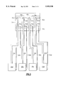
- FIG. 2 is a front cross-sectional view illustrating the interior of an evaporator used in preferred embodiments of the present invention
- FIG. 3 is a rear elevation view illustrating the arrangement of thermosyphon cooling systems in the present invention in the circumstance in which multiple modules are to be cooled;
- FIG. 4 is a rear elevation view illustrating the employment of the cooling system of the present invention in a frame and cabinet for a data processing system.
- FIG. 1A illustrates a thermosyphon arrangement which is particularly useful for employing the evaporator of the present invention.
- thermosyphon system 10 shown in FIG. 1A includes evaporator 20 which discharges vapor phase coolant into vapor discharge plenum 41 from evaporator 20.
- Plenum 41 preferably comprises a cylindrical central section having a rectangular entrance port and a cylindrical exit port which feeds directly into flexible vapor line 40.
- Vapor line 40 supplies a similarly constructed vapor plenum 43 as a supply input to condenser 30.
- Condenser 30 removes heat from the vapor phase coolant and produces liquid condensate material which flows into liquid plenum 42 and thence to liquid condensate return line 50 which is connected to a lower portion of evaporator 20. In this way, electronic module 70 is cooled by the boiling action of coolant within evaporator 20.
- FIG. 1B illustrates the inclusion of air-moving device 60 which moves air through condenser 30 to provide a heat rejection mechanism to the atmosphere, as illustrated by air flow lines 61 and 62.
- FIG. 2 provides a more detailed view of an evaporator which is especially useful in the thermosyphon cooling system of the present invention.
- evaporator 20 includes housing 26 having a substantially flat exterior portion which is in direct thermal contact with the electronic module to be cooled. This surface does not have to be flat; it could conform to the object to be cooled. However, design economies and convenience certainly dictate that the flat design is the preferable choice for the configuration of housing 26.
- housing 26 there is provided a first (liquid phase) conduit 21 which receives return flow from condenser 30 through condensate return line 50 via inlet port 27.
- housing 26 includes a second (vapor phase) conduit 22 which extends downwardly from outlet port 28 positioned on an upper portion of housing 26.
- the positioning of inlet port 27 and outlet port 28 is meant to facilitate the gravitationally induced flow of coolant through evaporator 23.
- evaporator chambers 23A through 23E each of which extends between conduits 21 and 22.
- These evaporator chambers further include canted baffles 25 which serve to direct the flow of coolant in a uniform manner toward the connections that chambers 23A through 23E have with vapor phase conduit 22.
- chambers 23A through 23E include perforated plates 24A through 24E disposed in their respective evaporation chambers. Plates 24A through 24E and baffles 25 serve to provide a more uniform flow of coolant through evaporator 20. In this way, the chances are reduced that a particular point within the evaporator becomes "dry” in the sense that coolant is converted entirely into the vapor phase which, therefore, does not thoroughly wet the thermally conductive surface provided for module cooling.
- thermosyphon system is preferably maintained at a level such that boiling of liquid in the system takes place at a temperature which is at or below an operation range for the particular electronics module(s) being cooled.
- FIG. 3 illustrates an arrangement of modular thermosyphon systems employed for cooling a plurality of separate electronic modules. These thermosyphon systems are substantially as shown in FIG. 1 except that, in FIG. 3 as shown, separate portions have been designated by adding a lower case alphabetic character, namely, a, b, c or d, to the reference numeral employed for the corresponding single system version shown in FIG. 1.
- condenser 30 includes four condenser portions, 30a through 30d, all of which are cooled by means of two air-moving devices, fan 60a and fan 60b, configured to operate in a push-pull configuration.
- FIG. 4 illustrates, in rear elevation view format, the thermosyphon system of the present invention being employed to cool two electronic modules (not visible) disposed on printed circuit board 90.
- Other printed circuit boards may also be disposed within frame 80 mounted in a fashion substantially parallel to printed circuit board 90.
- Other circuit boards 91 and 92 may also be disposed within frame 80 in a direction substantially orthogonal to circuit board 90. These boards may include other electronic components which are not heat critical.
- condenser 30 is disposed in a position which is removed from the central portion of the frame and yet which is nonetheless positioned at a location from which heated air is readily employed as the mechanism for removing heat from condenser 30.
- the liquid supply section feeding evaporator chambers 23A through 23E is preferably tapered in the horizontal direction.
- the tapering of the liquid supply, together with perforated flow control plates 24A through 24E, ensures that liquid coolant is uniformly distributed to the surfaces of fins 25 for boiling.
- a tapered vapor channel which feeds vapor conduit 22.
- the actual routing of the vapor and condensate lines are as preferably shown in FIG. 4. Because of the highly effective nature of boiling heat transfer, the vapor line does not need to be very large. A flexible line carrying the vapor from the evaporator to the condenser is routed through the supporting structure of the frame. The even smaller condensate line is also tucked out of the way in structural parts.
- the present invention solves several problems including the elimination of redundant pumps which are generally required for coolant circulation. Additionally, there is eliminated any need for an expansion tank.
- the cooling system described herein reduces the volume of cooling hardware which is required in the volume immediately adjacent to the electronics and, therefore, is seen to reduce the board or card pitch which therefore leads to closer spacing of processor boards.
- the apparatus shown herein provides a cooling system which is relatively insensitive to module power variations and, additionally, provides the capability of higher processor performance and shorter signal paths.
- all of the objects cited above are in fact met by the cooling system and apparatus described herein.
Abstract
Description
Claims (6)
Priority Applications (1)
| Application Number | Priority Date | Filing Date | Title |
|---|---|---|---|
| US09/052,416 US5953930A (en) | 1998-03-31 | 1998-03-31 | Evaporator for use in an extended air cooling system for electronic components |
Applications Claiming Priority (1)
| Application Number | Priority Date | Filing Date | Title |
|---|---|---|---|
| US09/052,416 US5953930A (en) | 1998-03-31 | 1998-03-31 | Evaporator for use in an extended air cooling system for electronic components |
Publications (1)
| Publication Number | Publication Date |
|---|---|
| US5953930A true US5953930A (en) | 1999-09-21 |
Family
ID=21977482
Family Applications (1)
| Application Number | Title | Priority Date | Filing Date |
|---|---|---|---|
| US09/052,416 Expired - Fee Related US5953930A (en) | 1998-03-31 | 1998-03-31 | Evaporator for use in an extended air cooling system for electronic components |
Country Status (1)
| Country | Link |
|---|---|
| US (1) | US5953930A (en) |
Cited By (56)
| Publication number | Priority date | Publication date | Assignee | Title |
|---|---|---|---|---|
| US6223810B1 (en) * | 1998-03-31 | 2001-05-01 | International Business Machines | Extended air cooling with heat loop for dense or compact configurations of electronic components |
| US6237353B1 (en) * | 1999-07-29 | 2001-05-29 | Carrier Corporation | System for removing parasitic losses in a refrigeration unit |
| US6388882B1 (en) | 2001-07-19 | 2002-05-14 | Thermal Corp. | Integrated thermal architecture for thermal management of high power electronics |
| US6442959B1 (en) * | 2000-06-28 | 2002-09-03 | Twinbird Corporation | Thermosiphon for refrigerating machine |
| US6504719B2 (en) * | 2001-03-30 | 2003-01-07 | Intel Corporation | Computer system that can be operated without a cooling fan |
| US6506111B2 (en) | 2001-05-16 | 2003-01-14 | Sanmina-Sci Corporation | Cooling airflow distribution device |
| US6516954B2 (en) | 2000-06-29 | 2003-02-11 | Servervault Corp. | Equipment rack with integral HVAC and power distribution features |
| WO2003016810A1 (en) | 2001-07-27 | 2003-02-27 | Siemens Aktiengesellschaft | Method and device for preventing the formation of a gas film in an evaporation area in a double phase cooling system |
| US6536510B2 (en) | 2001-07-10 | 2003-03-25 | Thermal Corp. | Thermal bus for cabinets housing high power electronics equipment |
| US6650543B2 (en) * | 2002-02-08 | 2003-11-18 | Hon Hai Precision Ind. Co., Ltd. | Heat dissipation device |
| US6657121B2 (en) * | 2001-06-27 | 2003-12-02 | Thermal Corp. | Thermal management system and method for electronics system |
| US20040031593A1 (en) * | 2002-03-18 | 2004-02-19 | Ernst Donald M. | Heat pipe diode assembly and method |
| US6761212B2 (en) * | 2000-05-25 | 2004-07-13 | Liebert Corporation | Spiral copper tube and aluminum fin thermosyphon heat exchanger |
| US6856037B2 (en) * | 2001-11-26 | 2005-02-15 | Sony Corporation | Method and apparatus for converting dissipated heat to work energy |
| US20050063158A1 (en) * | 2003-09-16 | 2005-03-24 | Sgl Carbon Ag | Cooling device for electronic and electrical components |
| US20050150242A1 (en) * | 2002-03-15 | 2005-07-14 | Siemens Aktiengesellschaft | Refrigeration plant for parts of installation, which are to be chilled |
| US20050217829A1 (en) * | 2004-03-31 | 2005-10-06 | Alex Belits | Low-profile thermosyphon-based cooling system for computers and other electronic devices |
| US20050225936A1 (en) * | 2002-03-28 | 2005-10-13 | Tony Day | Cooling of a data centre |
| US20060087811A1 (en) * | 2004-10-21 | 2006-04-27 | Foxconn Technology Co., Ltd | Heat dissipation device for lowering temperature of an airflow |
| US20060087810A1 (en) * | 2004-10-25 | 2006-04-27 | Uwe Rockenfeller | Apparatus and method for cooling electronics and computer components with managed and prioritized directional air flow heat rejection |
| US20070167125A1 (en) * | 2006-01-19 | 2007-07-19 | American Power Conversion Corporation | Cooling system and method |
| US20070163748A1 (en) * | 2006-01-19 | 2007-07-19 | American Power Conversion Corporation | Cooling system and method |
| US20070188994A1 (en) * | 2006-02-14 | 2007-08-16 | Ming-Kun Tsai | CPU cooler |
| US20070242438A1 (en) * | 2004-03-31 | 2007-10-18 | Belits Computer Systems, Inc. | Low-Profile Thermosyphon-Based Cooling System for Computers and Other Electronic Devices |
| US20080007913A1 (en) * | 2006-07-06 | 2008-01-10 | Hybricon Corporation | Card Cage With Parallel Flow Paths Having Substantially Similar Lengths |
| US20080041076A1 (en) * | 2006-08-15 | 2008-02-21 | American Power Conversion Corporation | Method and apparatus for cooling |
| US20080066889A1 (en) * | 2003-02-19 | 2008-03-20 | Isothermal Systems Research | Heat exchanging fluid return manifold for a liquid cooling system |
| US20080106865A1 (en) * | 2006-11-08 | 2008-05-08 | Chin-Kuang Luo | Computer module |
| US20080142068A1 (en) * | 2006-12-18 | 2008-06-19 | American Power Conversion Corporation | Direct Thermoelectric chiller assembly |
| US20080245083A1 (en) * | 2006-08-15 | 2008-10-09 | American Power Conversion Corporation | Method and apparatus for cooling |
| US20090019875A1 (en) * | 2007-07-19 | 2009-01-22 | American Power Conversion Corporation | A/v cooling system and method |
| US20090030554A1 (en) * | 2007-07-26 | 2009-01-29 | Bean Jr John H | Cooling control device and method |
| US7556086B2 (en) | 2001-04-06 | 2009-07-07 | University Of Maryland, College Park | Orientation-independent thermosyphon heat spreader |
| US20090241578A1 (en) * | 2008-03-31 | 2009-10-01 | Exaflop Llc | Warm Floor Data Center |
| US20100057263A1 (en) * | 2006-08-15 | 2010-03-04 | Ozan Tutunoglu | Method and apparatus for cooling |
| US20100170663A1 (en) * | 2006-12-18 | 2010-07-08 | American Power Conversion Corporation | Modular ice storage for uninterruptible chilled water |
| US8425287B2 (en) | 2007-01-23 | 2013-04-23 | Schneider Electric It Corporation | In-row air containment and cooling system and method |
| US8688413B2 (en) | 2010-12-30 | 2014-04-01 | Christopher M. Healey | System and method for sequential placement of cooling resources within data center layouts |
| CN104115579A (en) * | 2012-02-14 | 2014-10-22 | 日本电气株式会社 | Cooling device and cooling system |
| WO2016117342A1 (en) * | 2015-01-21 | 2016-07-28 | パナソニックIpマネジメント株式会社 | Cooling device and electronic device in which same is installed |
| US9451731B2 (en) | 2006-01-19 | 2016-09-20 | Schneider Electric It Corporation | Cooling system and method |
| US20170265329A1 (en) * | 2016-03-11 | 2017-09-14 | Eaton Corporation | Thermosyphon cooling apparatus with isolation of cooled components |
| US9830410B2 (en) | 2011-12-22 | 2017-11-28 | Schneider Electric It Corporation | System and method for prediction of temperature values in an electronics system |
| US9952103B2 (en) | 2011-12-22 | 2018-04-24 | Schneider Electric It Corporation | Analysis of effect of transient events on temperature in a data center |
| US9996659B2 (en) | 2009-05-08 | 2018-06-12 | Schneider Electric It Corporation | System and method for arranging equipment in a data center |
| US10123461B2 (en) | 2017-04-05 | 2018-11-06 | Google Llc | Cooling electronic devices in a data center with cooling units mounted in bays of a server rack frame assembly |
| US10209003B2 (en) | 2012-02-21 | 2019-02-19 | Thermal Corp. | Electronics cabinet and rack cooling system and method |
| US20190086157A1 (en) * | 2016-03-04 | 2019-03-21 | Nec Corporation | Cooling system, cooler, and cooling method |
| US10349561B2 (en) | 2016-04-15 | 2019-07-09 | Google Llc | Cooling electronic devices in a data center |
| US10448543B2 (en) | 2015-05-04 | 2019-10-15 | Google Llc | Cooling electronic devices in a data center |
| CN110822779A (en) * | 2019-10-08 | 2020-02-21 | 浙江省海洋水产研究所 | Shelf type quick-freezing device for fish catch on sea catch boat |
| US10709034B2 (en) | 2018-02-21 | 2020-07-07 | Google Llc | Supporting rack-mounted computing devices |
| US10785895B2 (en) | 2017-10-04 | 2020-09-22 | Google Llc | Managing a data center |
| US10888013B2 (en) | 2017-10-04 | 2021-01-05 | Google Llc | Managing a data center |
| US10928869B2 (en) * | 2018-12-05 | 2021-02-23 | Acer Incorporated | Heat dissipation module |
| US11076507B2 (en) | 2007-05-15 | 2021-07-27 | Schneider Electric It Corporation | Methods and systems for managing facility power and cooling |
Citations (14)
| Publication number | Priority date | Publication date | Assignee | Title |
|---|---|---|---|---|
| US3317798A (en) * | 1966-04-13 | 1967-05-02 | Ibm | Cooling electrical apparatus |
| US3387648A (en) * | 1967-02-23 | 1968-06-11 | Navy Usa | Cabinet enclosed recirculation cooling system carried on extensible chassis mountingelectronic modules |
| US4602679A (en) * | 1982-03-22 | 1986-07-29 | Grumman Aerospace Corporation | Capillary-pumped heat transfer panel and system |
| US4793405A (en) * | 1985-12-13 | 1988-12-27 | Hasler Ag. | Process and apparatus for dissipating the heat loss of at least one assembly of electrical elements |
| US5003376A (en) * | 1989-03-28 | 1991-03-26 | Coriolis Corporation | Cooling of large high power semi-conductors |
| US5063475A (en) * | 1990-03-19 | 1991-11-05 | International Business Machines Corporation | Multileveled electronic assembly with cooling means |
| US5077601A (en) * | 1988-09-09 | 1991-12-31 | Hitachi, Ltd. | Cooling system for cooling an electronic device and heat radiation fin for use in the cooling system |
| US5150278A (en) * | 1991-04-16 | 1992-09-22 | J. E. Thomas Specialties Limited | Finned housing |
| US5329425A (en) * | 1991-02-25 | 1994-07-12 | Alcatel N.V. | Cooling system |
| US5361188A (en) * | 1990-10-24 | 1994-11-01 | Hitachi Ltd. | Cooling apparatus of electronic equipment |
| US5513071A (en) * | 1994-11-28 | 1996-04-30 | Philips Electronics North America Corporation | Electronics housing with improved heat rejection |
| US5587880A (en) * | 1995-06-28 | 1996-12-24 | Aavid Laboratories, Inc. | Computer cooling system operable under the force of gravity in first orientation and against the force of gravity in second orientation |
| JPH0969595A (en) * | 1995-09-01 | 1997-03-11 | Yaskawa Electric Corp | Electronic equipment unit |
| US5613552A (en) * | 1994-07-13 | 1997-03-25 | Nippondenso Co., Ltd. | Cooling apparatus using boiling and condensing refrigerant |
-
1998
- 1998-03-31 US US09/052,416 patent/US5953930A/en not_active Expired - Fee Related
Patent Citations (14)
| Publication number | Priority date | Publication date | Assignee | Title |
|---|---|---|---|---|
| US3317798A (en) * | 1966-04-13 | 1967-05-02 | Ibm | Cooling electrical apparatus |
| US3387648A (en) * | 1967-02-23 | 1968-06-11 | Navy Usa | Cabinet enclosed recirculation cooling system carried on extensible chassis mountingelectronic modules |
| US4602679A (en) * | 1982-03-22 | 1986-07-29 | Grumman Aerospace Corporation | Capillary-pumped heat transfer panel and system |
| US4793405A (en) * | 1985-12-13 | 1988-12-27 | Hasler Ag. | Process and apparatus for dissipating the heat loss of at least one assembly of electrical elements |
| US5077601A (en) * | 1988-09-09 | 1991-12-31 | Hitachi, Ltd. | Cooling system for cooling an electronic device and heat radiation fin for use in the cooling system |
| US5003376A (en) * | 1989-03-28 | 1991-03-26 | Coriolis Corporation | Cooling of large high power semi-conductors |
| US5063475A (en) * | 1990-03-19 | 1991-11-05 | International Business Machines Corporation | Multileveled electronic assembly with cooling means |
| US5361188A (en) * | 1990-10-24 | 1994-11-01 | Hitachi Ltd. | Cooling apparatus of electronic equipment |
| US5329425A (en) * | 1991-02-25 | 1994-07-12 | Alcatel N.V. | Cooling system |
| US5150278A (en) * | 1991-04-16 | 1992-09-22 | J. E. Thomas Specialties Limited | Finned housing |
| US5613552A (en) * | 1994-07-13 | 1997-03-25 | Nippondenso Co., Ltd. | Cooling apparatus using boiling and condensing refrigerant |
| US5513071A (en) * | 1994-11-28 | 1996-04-30 | Philips Electronics North America Corporation | Electronics housing with improved heat rejection |
| US5587880A (en) * | 1995-06-28 | 1996-12-24 | Aavid Laboratories, Inc. | Computer cooling system operable under the force of gravity in first orientation and against the force of gravity in second orientation |
| JPH0969595A (en) * | 1995-09-01 | 1997-03-11 | Yaskawa Electric Corp | Electronic equipment unit |
Non-Patent Citations (2)
| Title |
|---|
| Chrysler et al., "Enhanced Thermosyphon Cooling System," IBM Technical Disclosure Bulletin vol. 37, No. 10, Oct. 1994, pp. 11-12. |
| Chrysler et al., Enhanced Thermosyphon Cooling System, IBM Technical Disclosure Bulletin vol. 37, No. 10, Oct. 1994, pp. 11 12. * |
Cited By (102)
| Publication number | Priority date | Publication date | Assignee | Title |
|---|---|---|---|---|
| US6223810B1 (en) * | 1998-03-31 | 2001-05-01 | International Business Machines | Extended air cooling with heat loop for dense or compact configurations of electronic components |
| US6237353B1 (en) * | 1999-07-29 | 2001-05-29 | Carrier Corporation | System for removing parasitic losses in a refrigeration unit |
| US6761212B2 (en) * | 2000-05-25 | 2004-07-13 | Liebert Corporation | Spiral copper tube and aluminum fin thermosyphon heat exchanger |
| US6442959B1 (en) * | 2000-06-28 | 2002-09-03 | Twinbird Corporation | Thermosiphon for refrigerating machine |
| US6516954B2 (en) | 2000-06-29 | 2003-02-11 | Servervault Corp. | Equipment rack with integral HVAC and power distribution features |
| US6504719B2 (en) * | 2001-03-30 | 2003-01-07 | Intel Corporation | Computer system that can be operated without a cooling fan |
| US7556086B2 (en) | 2001-04-06 | 2009-07-07 | University Of Maryland, College Park | Orientation-independent thermosyphon heat spreader |
| US6506111B2 (en) | 2001-05-16 | 2003-01-14 | Sanmina-Sci Corporation | Cooling airflow distribution device |
| US7011576B2 (en) | 2001-05-16 | 2006-03-14 | Sanmina Sci Corporation | Cooling airflow distribution device |
| US20050250435A1 (en) * | 2001-05-16 | 2005-11-10 | Sharp Anthony C | Cooling airflow distribution device |
| US6652374B2 (en) | 2001-05-16 | 2003-11-25 | Sanmina-Sci Corporation | Cooling airflow distribution device |
| US6652373B2 (en) | 2001-05-16 | 2003-11-25 | Sanmina-Sci Corporation | Cooling airflow distribution device |
| US7309279B2 (en) | 2001-05-16 | 2007-12-18 | Sanmina-Sci Corporation | Cooling airflow distribution device |
| US20040180620A1 (en) * | 2001-05-16 | 2004-09-16 | Sharp Anthony C | Cooling airflow distribution device |
| US6657121B2 (en) * | 2001-06-27 | 2003-12-02 | Thermal Corp. | Thermal management system and method for electronics system |
| US20040045730A1 (en) * | 2001-06-27 | 2004-03-11 | Garner Scott D. | Thermal management system and method for electronics system |
| US7071408B2 (en) | 2001-06-27 | 2006-07-04 | Thermal Corp. | Thermal management system and method for electronics system |
| US6972365B2 (en) | 2001-06-27 | 2005-12-06 | Thermal Corp. | Thermal management system and method for electronics system |
| US20060005980A1 (en) * | 2001-06-27 | 2006-01-12 | Garner Scott D | Thermal management system and method for electronics system |
| US6536510B2 (en) | 2001-07-10 | 2003-03-25 | Thermal Corp. | Thermal bus for cabinets housing high power electronics equipment |
| US6388882B1 (en) | 2001-07-19 | 2002-05-14 | Thermal Corp. | Integrated thermal architecture for thermal management of high power electronics |
| WO2003016810A1 (en) | 2001-07-27 | 2003-02-27 | Siemens Aktiengesellschaft | Method and device for preventing the formation of a gas film in an evaporation area in a double phase cooling system |
| US6856037B2 (en) * | 2001-11-26 | 2005-02-15 | Sony Corporation | Method and apparatus for converting dissipated heat to work energy |
| US6650543B2 (en) * | 2002-02-08 | 2003-11-18 | Hon Hai Precision Ind. Co., Ltd. | Heat dissipation device |
| US20050150242A1 (en) * | 2002-03-15 | 2005-07-14 | Siemens Aktiengesellschaft | Refrigeration plant for parts of installation, which are to be chilled |
| US7174737B2 (en) * | 2002-03-15 | 2007-02-13 | Siemens Aktiengesellschaft | Refrigeration plant for parts of installation, which are to be chilled |
| US20040031593A1 (en) * | 2002-03-18 | 2004-02-19 | Ernst Donald M. | Heat pipe diode assembly and method |
| US7534167B2 (en) | 2002-03-28 | 2009-05-19 | American Power Conversion Corporation | Data center cooling |
| US20050225936A1 (en) * | 2002-03-28 | 2005-10-13 | Tony Day | Cooling of a data centre |
| US7878889B2 (en) | 2002-03-28 | 2011-02-01 | American Power Conversion Corporation | Data center cooling |
| US20090173473A1 (en) * | 2002-03-28 | 2009-07-09 | American Power Conversion Corporation | Data center cooling |
| US20110094714A1 (en) * | 2002-03-28 | 2011-04-28 | American Power Conversion Corporation | Data center cooling |
| US7867070B2 (en) | 2002-03-28 | 2011-01-11 | American Power Conversion Corporation | Data center cooling |
| US9392733B2 (en) | 2002-03-28 | 2016-07-12 | Schneider Electric It Corporation | Data center cooling |
| US20070213000A1 (en) * | 2002-03-28 | 2007-09-13 | American Power Conversion | Data Center Cooling |
| US8157626B2 (en) | 2002-03-28 | 2012-04-17 | American Power Conversion Corporation | Data center cooling |
| US20080066889A1 (en) * | 2003-02-19 | 2008-03-20 | Isothermal Systems Research | Heat exchanging fluid return manifold for a liquid cooling system |
| US20050063158A1 (en) * | 2003-09-16 | 2005-03-24 | Sgl Carbon Ag | Cooling device for electronic and electrical components |
| US7231961B2 (en) * | 2004-03-31 | 2007-06-19 | Belits Computer Systems, Inc. | Low-profile thermosyphon-based cooling system for computers and other electronic devices |
| US20070242438A1 (en) * | 2004-03-31 | 2007-10-18 | Belits Computer Systems, Inc. | Low-Profile Thermosyphon-Based Cooling System for Computers and Other Electronic Devices |
| US7958935B2 (en) * | 2004-03-31 | 2011-06-14 | Belits Computer Systems, Inc. | Low-profile thermosyphon-based cooling system for computers and other electronic devices |
| US20050217829A1 (en) * | 2004-03-31 | 2005-10-06 | Alex Belits | Low-profile thermosyphon-based cooling system for computers and other electronic devices |
| EA012095B1 (en) * | 2004-03-31 | 2009-08-28 | Белитс Компьютер Системс, Инк. | Low-profile thermosyphon-based cooling system for computers and other electronic devices |
| WO2005098335A3 (en) * | 2004-03-31 | 2007-05-10 | Belits Comp Systems Inc | Low-profile thermosyphon cooling system for computers |
| US20060087811A1 (en) * | 2004-10-21 | 2006-04-27 | Foxconn Technology Co., Ltd | Heat dissipation device for lowering temperature of an airflow |
| US20060087810A1 (en) * | 2004-10-25 | 2006-04-27 | Uwe Rockenfeller | Apparatus and method for cooling electronics and computer components with managed and prioritized directional air flow heat rejection |
| US7212403B2 (en) | 2004-10-25 | 2007-05-01 | Rocky Research | Apparatus and method for cooling electronics and computer components with managed and prioritized directional air flow heat rejection |
| US9451731B2 (en) | 2006-01-19 | 2016-09-20 | Schneider Electric It Corporation | Cooling system and method |
| US8672732B2 (en) | 2006-01-19 | 2014-03-18 | Schneider Electric It Corporation | Cooling system and method |
| US20070163748A1 (en) * | 2006-01-19 | 2007-07-19 | American Power Conversion Corporation | Cooling system and method |
| US20070167125A1 (en) * | 2006-01-19 | 2007-07-19 | American Power Conversion Corporation | Cooling system and method |
| US7352580B2 (en) * | 2006-02-14 | 2008-04-01 | Hua-Hsin Tsai | CPU cooler |
| US20070188994A1 (en) * | 2006-02-14 | 2007-08-16 | Ming-Kun Tsai | CPU cooler |
| US7450384B2 (en) | 2006-07-06 | 2008-11-11 | Hybricon Corporation | Card cage with parallel flow paths having substantially similar lengths |
| US20080007913A1 (en) * | 2006-07-06 | 2008-01-10 | Hybricon Corporation | Card Cage With Parallel Flow Paths Having Substantially Similar Lengths |
| US9115916B2 (en) | 2006-08-15 | 2015-08-25 | Schneider Electric It Corporation | Method of operating a cooling system having one or more cooling units |
| US20100057263A1 (en) * | 2006-08-15 | 2010-03-04 | Ozan Tutunoglu | Method and apparatus for cooling |
| US20080245083A1 (en) * | 2006-08-15 | 2008-10-09 | American Power Conversion Corporation | Method and apparatus for cooling |
| US9568206B2 (en) | 2006-08-15 | 2017-02-14 | Schneider Electric It Corporation | Method and apparatus for cooling |
| US20080041076A1 (en) * | 2006-08-15 | 2008-02-21 | American Power Conversion Corporation | Method and apparatus for cooling |
| US8322155B2 (en) | 2006-08-15 | 2012-12-04 | American Power Conversion Corporation | Method and apparatus for cooling |
| US8327656B2 (en) | 2006-08-15 | 2012-12-11 | American Power Conversion Corporation | Method and apparatus for cooling |
| US7525801B2 (en) * | 2006-11-08 | 2009-04-28 | Chin-Kuang Luo | Computer module |
| US20080106865A1 (en) * | 2006-11-08 | 2008-05-08 | Chin-Kuang Luo | Computer module |
| US8424336B2 (en) | 2006-12-18 | 2013-04-23 | Schneider Electric It Corporation | Modular ice storage for uninterruptible chilled water |
| US9080802B2 (en) | 2006-12-18 | 2015-07-14 | Schneider Electric It Corporation | Modular ice storage for uninterruptible chilled water |
| US20100170663A1 (en) * | 2006-12-18 | 2010-07-08 | American Power Conversion Corporation | Modular ice storage for uninterruptible chilled water |
| US20080142068A1 (en) * | 2006-12-18 | 2008-06-19 | American Power Conversion Corporation | Direct Thermoelectric chiller assembly |
| US8425287B2 (en) | 2007-01-23 | 2013-04-23 | Schneider Electric It Corporation | In-row air containment and cooling system and method |
| US11076507B2 (en) | 2007-05-15 | 2021-07-27 | Schneider Electric It Corporation | Methods and systems for managing facility power and cooling |
| US11503744B2 (en) | 2007-05-15 | 2022-11-15 | Schneider Electric It Corporation | Methods and systems for managing facility power and cooling |
| US20090019875A1 (en) * | 2007-07-19 | 2009-01-22 | American Power Conversion Corporation | A/v cooling system and method |
| US20090030554A1 (en) * | 2007-07-26 | 2009-01-29 | Bean Jr John H | Cooling control device and method |
| US20090241578A1 (en) * | 2008-03-31 | 2009-10-01 | Exaflop Llc | Warm Floor Data Center |
| US8763414B2 (en) * | 2008-03-31 | 2014-07-01 | Google Inc. | Warm floor data center |
| US9996659B2 (en) | 2009-05-08 | 2018-06-12 | Schneider Electric It Corporation | System and method for arranging equipment in a data center |
| US10614194B2 (en) | 2009-05-08 | 2020-04-07 | Schneider Electric It Corporation | System and method for arranging equipment in a data center |
| US8688413B2 (en) | 2010-12-30 | 2014-04-01 | Christopher M. Healey | System and method for sequential placement of cooling resources within data center layouts |
| US9830410B2 (en) | 2011-12-22 | 2017-11-28 | Schneider Electric It Corporation | System and method for prediction of temperature values in an electronics system |
| US9952103B2 (en) | 2011-12-22 | 2018-04-24 | Schneider Electric It Corporation | Analysis of effect of transient events on temperature in a data center |
| CN104115579A (en) * | 2012-02-14 | 2014-10-22 | 日本电气株式会社 | Cooling device and cooling system |
| CN104115579B (en) * | 2012-02-14 | 2016-10-12 | 日本电气株式会社 | Cooling device and cooling system |
| US10209003B2 (en) | 2012-02-21 | 2019-02-19 | Thermal Corp. | Electronics cabinet and rack cooling system and method |
| WO2016117342A1 (en) * | 2015-01-21 | 2016-07-28 | パナソニックIpマネジメント株式会社 | Cooling device and electronic device in which same is installed |
| US10448543B2 (en) | 2015-05-04 | 2019-10-15 | Google Llc | Cooling electronic devices in a data center |
| US11109517B2 (en) | 2015-05-04 | 2021-08-31 | Google Llc | Cooling electronic devices in a data center |
| US20190086157A1 (en) * | 2016-03-04 | 2019-03-21 | Nec Corporation | Cooling system, cooler, and cooling method |
| US10178803B2 (en) * | 2016-03-11 | 2019-01-08 | Eaton Intelligent Power Limited | Thermosyphon cooling apparatus with isolation of cooled components |
| US20170265329A1 (en) * | 2016-03-11 | 2017-09-14 | Eaton Corporation | Thermosyphon cooling apparatus with isolation of cooled components |
| US10349561B2 (en) | 2016-04-15 | 2019-07-09 | Google Llc | Cooling electronic devices in a data center |
| US10888029B2 (en) | 2017-04-05 | 2021-01-05 | Google Llc | Data center cooling system with stacked rows of server racks |
| US10123461B2 (en) | 2017-04-05 | 2018-11-06 | Google Llc | Cooling electronic devices in a data center with cooling units mounted in bays of a server rack frame assembly |
| US11297736B2 (en) | 2017-04-05 | 2022-04-05 | Google Llc | Data center cooling system with stacked rows of server racks |
| US10785895B2 (en) | 2017-10-04 | 2020-09-22 | Google Llc | Managing a data center |
| US10888013B2 (en) | 2017-10-04 | 2021-01-05 | Google Llc | Managing a data center |
| US11357135B2 (en) | 2017-10-04 | 2022-06-07 | Google Llc | Managing a data center |
| US11395432B2 (en) | 2017-10-04 | 2022-07-19 | Google Llc | Managing a data center |
| US10709034B2 (en) | 2018-02-21 | 2020-07-07 | Google Llc | Supporting rack-mounted computing devices |
| US11477908B2 (en) | 2018-02-21 | 2022-10-18 | Google Llc | Supporting rack-mounted computing devices |
| US10928869B2 (en) * | 2018-12-05 | 2021-02-23 | Acer Incorporated | Heat dissipation module |
| CN110822779B (en) * | 2019-10-08 | 2021-11-19 | 浙江省海洋水产研究所 | Shelf type quick-freezing device for fish catch on sea catch boat |
| CN110822779A (en) * | 2019-10-08 | 2020-02-21 | 浙江省海洋水产研究所 | Shelf type quick-freezing device for fish catch on sea catch boat |
Similar Documents
| Publication | Publication Date | Title |
|---|---|---|
| US5953930A (en) | Evaporator for use in an extended air cooling system for electronic components | |
| US6223810B1 (en) | Extended air cooling with heat loop for dense or compact configurations of electronic components | |
| US8203842B2 (en) | Open flow cold plate for immersion-cooled electronic packages | |
| US6536510B2 (en) | Thermal bus for cabinets housing high power electronics equipment | |
| US6804117B2 (en) | Thermal bus for electronics systems | |
| EP0898220B1 (en) | Electronic apparatus with improved heatsink arrangement | |
| US7104081B2 (en) | Condensate removal system and method for facilitating cooling of an electronics system | |
| US6496375B2 (en) | Cooling arrangement for high density packaging of electronic components | |
| EP3292459B1 (en) | Cooling electronic devices in a data center | |
| US10966352B2 (en) | Cooling electronic devices in a data center | |
| US7830664B2 (en) | Cooling apparatuses with discrete cold plates compliantly coupled between a common manifold and electronics components of an assembly to be cooled | |
| US5297005A (en) | Apparatus and method for cooling heat generating electronic components in a cabinet | |
| US7321494B2 (en) | Graphics card apparatus with improved heat dissipating mechanisms | |
| US7339792B2 (en) | Graphics card apparatus with improved heat dissipating assemblies | |
| US6754077B2 (en) | Heat dissipating apparatus for circuit boards | |
| TWI714338B (en) | Cooling electronic devices in a data center | |
| US10548240B1 (en) | Cooling electronic devices in a data center | |
| WO1995025255A1 (en) | Apparatus and method for cooling heat generating electronic components in a cabinet | |
| NL2011936A (en) | Thermosiphon systems for electronic devices. | |
| JP2008102964A (en) | Method and device for mounting computer components | |
| US6005771A (en) | Electronics cooling technique for spacecraft modules | |
| JP7418572B2 (en) | Nozzle array and cooling module | |
| EP3829278B1 (en) | Cooling arrangement for a server mountable in a server rack | |
| US11910562B2 (en) | Localized thermal accelerator in an immersion environment | |
| CN217825810U (en) | Single-phase immersed heat dissipation system |
Legal Events
| Date | Code | Title | Description |
|---|---|---|---|
| AS | Assignment |
Owner name: INTERNATIONAL BUSINESS MACHINES CORPORATION, NEW Y Free format text: ASSIGNMENT OF ASSIGNORS INTEREST;ASSIGNORS:CHU, RICHARD C.;CHRYSLER, GREGORY M.;REEL/FRAME:009129/0202;SIGNING DATES FROM 19980322 TO 19980326 |
|
| FEPP | Fee payment procedure |
Free format text: PAYOR NUMBER ASSIGNED (ORIGINAL EVENT CODE: ASPN); ENTITY STATUS OF PATENT OWNER: LARGE ENTITY |
|
| FPAY | Fee payment |
Year of fee payment: 4 |
|
| FPAY | Fee payment |
Year of fee payment: 8 |
|
| REMI | Maintenance fee reminder mailed | ||
| LAPS | Lapse for failure to pay maintenance fees | ||
| STCH | Information on status: patent discontinuation |
Free format text: PATENT EXPIRED DUE TO NONPAYMENT OF MAINTENANCE FEES UNDER 37 CFR 1.362 |
|
| FP | Lapsed due to failure to pay maintenance fee |
Effective date: 20110921 |