US5943473A - Heated cartridge humidifier - Google Patents
Heated cartridge humidifier Download PDFInfo
- Publication number
- US5943473A US5943473A US08/865,439 US86543997A US5943473A US 5943473 A US5943473 A US 5943473A US 86543997 A US86543997 A US 86543997A US 5943473 A US5943473 A US 5943473A
- Authority
- US
- United States
- Prior art keywords
- humidifier
- water
- housing
- cartridge
- end portion
- Prior art date
- Legal status (The legal status is an assumption and is not a legal conclusion. Google has not performed a legal analysis and makes no representation as to the accuracy of the status listed.)
- Expired - Lifetime
Links
Images


Classifications
-
- A—HUMAN NECESSITIES
- A61—MEDICAL OR VETERINARY SCIENCE; HYGIENE
- A61M—DEVICES FOR INTRODUCING MEDIA INTO, OR ONTO, THE BODY; DEVICES FOR TRANSDUCING BODY MEDIA OR FOR TAKING MEDIA FROM THE BODY; DEVICES FOR PRODUCING OR ENDING SLEEP OR STUPOR
- A61M16/00—Devices for influencing the respiratory system of patients by gas treatment, e.g. mouth-to-mouth respiration; Tracheal tubes
- A61M16/10—Preparation of respiratory gases or vapours
- A61M16/14—Preparation of respiratory gases or vapours by mixing different fluids, one of them being in a liquid phase
- A61M16/16—Devices to humidify the respiration air
- A61M16/162—Water-reservoir filling system, e.g. automatic
- A61M16/164—Water-reservoir filling system, e.g. automatic including a liquid inlet valve system
- A61M16/165—Water-reservoir filling system, e.g. automatic including a liquid inlet valve system with a float actuator
- A61M16/167—Water-reservoir filling system, e.g. automatic including a liquid inlet valve system with a float actuator acting vertically on the valve
Definitions
- the present invention relates generally to devices for delivering gases having a controlled vapor level and temperature to a delivery point, and more particularly to humidifier devices employing disposable humidifier cartridges which receive water from an adjacent container.
- Conventional systems for providing heated and moisturized respiratory gases basically fall into two groups; nebulizers, which produce aerosols of fine water droplets, and heated humidifiers, which supply heat and moisture to a gas by the passage of the gas through or over a heated water bath or evaporated surface.
- the present invention is concerned with the heated humidifiers.
- One such humidifier system includes a rigid, refillable water container designed to be placed upon a base unit having a heating element and is disclosed in U.S. Pat. No. 5,195,515 to Levine.
- This system includes a disposable heated cartridge humidifier for use with a collapsible water supply container and a heating device.
- the cartridge housing has a base plate fabricated from a conductive material such as metal, preferably aluminum. Included on the base plate is a peripheral lip which is crimped over a flange of a lower end of the housing.
- a humidifier housing has inlets for breathable gases and water, and an outlet for the humidified gases.
- a separate heating element provides the heat required to evaporate the water and humidify the gases passing through the housing.
- a base plate of the housing engages the heating element.
- the base plate includes a central heat conductive portion and an outer insulating portion to prevent lateral dissipation of the heat received from the heat source to the sidewall of the housing.
- Another feature is that an inlet of the humidifier cartridge extends deeply into the cartridge to promote humidification of the incoming breathable gas.
- a heated cartridge humidifier includes a humidifier housing configured to operationally engage a separate heat source.
- the housing has a sidewall with an open lower end portion and an integrally formed closed upper end portion, a breathable gas inlet, a water inlet, and a humidified gas outlet.
- a base plate of the housing is configured for being sealingly engaged to the open lower end of the housing. Included on the base plate is an insulating portion and a conductive portion. The insulating portion sealingly retains a perimeter of the conductive portion and provides an attachment point for the base plate to the housing.
- the conductive portion is configured to efficiently transfer heat received from the heat source to the water received from the water inlet and, therefore, humidify the breathable gases.
- FIG. 1 is partially exploded perspective view of the improved heated cartridge humidifier and heat source, with some parts omitted for clarity;
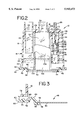
- FIG. 2 is a cross-section taken along the line 2--2 of FIG. 1 and in the direction generally indicated;
- FIG. 3 is a fragmentary vertical cross-sectional view of the base plate for the present improved heated cartridge humidifier
- FIG. 4 is a bottom plan view of the cartridge housing of the present improved heated cartridge humidifier.
- FIG. 5 is a vertical cross-section of an alternative embodiment of the present improved heated cartridge humidifier.
- an improved heater cartridge humidifier is shown and generally designated as 10, and is configured to be operationally engaged with a conventional heating unit, generally designated as 12.
- the humidifier cartridge 10 includes a humidifier housing 14 with a substantially vertical sidewall 16 and an upper end or top portion 18 integrally formed with the sidewall so as to define a humidifier chamber 20. Extending above and below the upper end portion 18 is a substantially cylindrical gas inlet 22 with a lower end 23. Appending from the upper end portion 18 is a substantially cylindrical gas delivery outlet 24.
- the gas inlet 22 and the gas delivery outlet 24 are adapted to be connected to a conventional breathable gas delivery system of the type used for respiratory patients.
- a nipple-like water inlet port 26, appending from the upper end portion 18, is adapted to be connected to a gravity feed collapsible water supply bag (not shown) as is well known in the art.
- the gas inlet 22, the gas delivery outlet 24 and the water inlet 26 are in fluid communication with the chamber 20.
- the housing 14 is made of transparent plastic such as polystyrene.
- transparent plastic such as polystyrene.
- the inlets 22 and 26, and the outlet 24 are disposed on the upper end portion 18, it is also contemplated that these features may be located elsewhere on the housing, such as on the sidewall 16.
- the water inlet 26 is in fluid communication with a water feed tube 27 depending from an underside 28 of the upper end portion 18.
- a lower end of the feed tube 27 includes nipple formation 30 with an axially disposed opening 32.
- a float retaining tube 34 depends from the underside 28 of the upper end portion 18 and circumscribes the water feed tube 27.
- the float retaining tube 34 includes a lower opening 36.
- a float 38 is dimensioned to be slidingly retained in the lower end 40 of the float retaining tube 34.
- the float 38 is essentially a tube of water tight buoyant material with a generally larger diameter lower end 40.
- An upper end portion 42 of the float 36 has a relatively smaller diameter than the lower end 40 and has a recess 44 into which a disc or pad 46 of rubber or other resilient material is secured.
- the dimensions and material used for the pad 46 are such that upon contact with the nipple formation 30, the axial opening 32 will be sealed, effectively cutting off the flow of water from the water inlet 26.
- the housing 14 is seated on a base plate 48 which includes a central conductive portion 50 and an insulating outer portion 52.
- a perimeter 54 of the central conductive portion 50 is sealingly retained within a groove 56 at an inner diameter 58 of the insulating portion 52.
- the central conductive portion 50 is preferably made of anodized aluminum but it is contemplated that other similar heat conductive materials would be equally useful.
- the conductive portion 50 is insert molded into the insulating portion 52. However, it is contemplated that alternative production techniques known to skilled practitioners may be utilized.
- a peripheral lip 60 extends vertically from an outer diameter 62 of the insulating portion 52.
- the insulating portion 52 is made of a plastic material such as polycarbonate, however, other known suitable heat insulating plastic materials are contemplated.
- an annular mating surface 63 Between the inner diameter 58 and the outer diameter 62 is disposed an annular mating surface 63 and an annular, generally arcuately shaped support formation 64.
- the peripheral lip 60 is interrupted in a plurality of positions about the outer diameter 62 to form recesses or notches 68.
- the notches 68 include notch lips 70 which are essentially the same height as peripheral lips 60 but are positioned closer to the mating surface 63 than to the peripheral lip 60. In operation, the notches 68 are used for properly engaging the cartridge 10 to the heating unit 12, as described below.
- the lower end of the sidewall 16 of the housing 14 has a radially projecting flange 72 which forms the attachment point for the base plate 48.
- the flange 72 is interrupted in a plurality of positions by notches 74 which correspond to the notches 68 on the outer diameter 62 of the insulating portion 52.
- the mating surface 63 of the insulating portion 52 includes a plurality of knobs 75 spaced about the base plate 48. Once the flange 72 is seated on the mating surface 63, the mating surface and the flange are preferably ultrasonically welded together.
- the knobs 75 provide sufficient material to form an absolute bond between the flange 72 and the surface 63. However, it is also contemplated that suitable chemical adhesives may be used to sealingly fasten the base plate 48 to the housing 14.
- Structural support is provided to the base plate 48 by the support formation 64.
- the arcuate shape of the support formation 64 exerts a preload or hold down force on the conductive portion, which holds it down against the heating unit 12.
- the heating unit 12 is designed to provide heat to the water delivered to the chamber 18 through the inlet 26 so that the water is more easily vaporized, and to provide water to a patient at a temperature which is as comfortable as possible.
- a housing 76 having a lower end 78 designed for positioning a substrate such as a shelf or a table, and an upper end 80.
- a control panel 82 is part of the heating unit 12 and is equipped with a temperature setting control 84 and various temperature warning lights and alarm indicators, generally designated as 86.
- a power switch 88, a power cord 90, and temperature sensor inputs 91 and 92 are preferably located on a panel 93 of the housing 76.
- the upper end 80 of the housing 76 has a heating surface 94 which is partially surrounded by a generally semicircular bracket 95.
- the bracket 95 is generally "C” or channel shaped in cross section to define an inwardly opening channel 96.
- a pivoting locking tab 98 is mounted to the upper end 80 of the housing 76 through use of a pivot member 100, which may be a pin or threaded fastener.
- the dimensions of the peripheral lip 60 and notch lip 70 of the base plate 48 are such that the cartridge 10 may be slid into the channel 96 to engage the bracket 95.
- the locking tab 98 is then moved to the vertical position as indicated in FIG. 1 to maintain the humidifier 10 in operational alignment upon the heating surface 94. In this position, the conductive portion 50 will be conductively heated by the heating surface 94.
- water is supplied through the water inlet 26 by the use of a gravity feed supply as is well known in the art.
- a gravity feed supply as is well known in the art.
- the float 38 rises until the disc 46 on the upper end portion 42 of the float 38 contacts the opening 32 of the feed tube 26 and effectively cuts off the flow of water into the housing 18. Breathable gases for treatment of patients enter the housing 14 through the gas inlet 22.
- a feature of the present humidifier 10 is that the extended lower end 23 of the inlet 22 directs the gases to the area immediately above the surface ⁇ L ⁇ of the water so that the gas is prevented from directly exiting through the outlet 24 without being properly humidified.
- Heat generated by the heating surface 92 is transferred through the conductive portion 50 to heat the water in the chamber 20 to vaporize the water and warm the gases.
- the water level ⁇ L ⁇ will fall due to evaporation.
- the float 38 will also fall, pulling the disc 46 away from the feed tube opening 32 to allow the lost water to be replaced.
- the conductive portion 50 being isolated from the sidewall 16 by the insulating portion 52, provides for superior heat transfer between the heating surface 92 and the water.
- the insulating portion 52 is dimensioned to separate the perimeter 56 of the conductive portion 50 from the sidewall 16 a sufficient distance to prevent the lateral dissipation of heat between the conductive portion and the sidewall. In this manner, heat is prevented from being dissipated to the ambient air, and is instead forced upward to warm the water. It has been found that the temperature of humidified gas measured at the outlet 24 is approximately 99° F., while prior art cartridges with totally conductive conventional base plates used at the same heater settings only produced humidified gas at 93° F. measured at the outlet 24.
- a partial sleeve 102 surrounded by a conventional paper-like wicking material 104, can be inserted in the chamber 20 generally underneath the gas delivery outlet 24.
- the sleeve 102 is preferably a rigid material such as aluminum and has a lower end 106 in contact with the conductive portion 50 of the base plate 48.
- a plurality of lugs 108 which are integrally formed with, and depend from the underside 28 of the upper end portion 18, provide the upper attachment point for the sleeve 102. It will be seen in FIG. 4 that the sleeve 102 is positioned within the chamber 20 to contact the gas inlet 22 at its apex. Also, an open portion 110 faces toward the float retaining tube 34.
- the material 104 draws water from the lower portion to the upper portion of the chamber 20.
- the sleeve is preferably made of anodized aluminum to assist in conducting heat into the chamber 20 and for vaporizing the water on the wicking material 104.
- the disposition of the sleeve 102 within the chamber 20 causes incoming air to travel in the direction of the arrows Q around the perimeter of the housing 14, where it is humidified before it can exit the chamber through the opening 10 and, ultimately through the outlet 24.
- an alternate embodiment of the humidifier 10 is generally designated 10a, and is preferred for use in pediatric respiratory therapy.
- Many of the features of the cartridge 10a shown in FIG. 5 are identical to those of the cartridge 10 as described above and are indicated with identical reference numbers.
- the cartridge 10a has been modified to provide for a smaller vaporization chamber 20a. It is believed that the smaller vaporization chamber 20a will prevent pediatric patients from becoming hyperventilated.
- the housing 14a has a sidewall 16a and an upper end portion 18a.
- the lower end 23a of the gas inlet 22a is relatively shorter than the lower end portion 23 of the gas inlet 22 of the housing 14 (FIG. 1). This accommodates the shorter sidewall 16a.
- the feed tube 26a, the float retaining tube 34a and the upper end 40a and the lower end 42a of the float 38a are dimensioned to accommodate a smaller housing 14a.
- the base plate 48 is identical to that described above and it attaches to the housing 14a in identical fashion. Further, if desired, an appropriately dimensioned sleeve and wicking material (not shown) could be inserted into the chamber 18a and retained by the lugs 108.
- the cartridge 110a works in an identical fashion as the cartridge 10 except the cartridge 110a has a smaller air and water volume.
- a major advantage of the present heated cartridge humidifier is that the heating and humidification of respiratory gases can be readily accomplished.
- the seal between the humidifier housing is improved to prevent leaking while providing for an efficient transfer of heat between a heat source and the water.
- Another advantage of the present invention is that it provides for enhanced humidification of the breathable gas prior to transmittal to the patient.
Abstract
Description
Claims (15)
Priority Applications (1)
| Application Number | Priority Date | Filing Date | Title |
|---|---|---|---|
| US08/865,439 US5943473A (en) | 1997-05-29 | 1997-05-29 | Heated cartridge humidifier |
Applications Claiming Priority (1)
| Application Number | Priority Date | Filing Date | Title |
|---|---|---|---|
| US08/865,439 US5943473A (en) | 1997-05-29 | 1997-05-29 | Heated cartridge humidifier |
Publications (1)
| Publication Number | Publication Date |
|---|---|
| US5943473A true US5943473A (en) | 1999-08-24 |
Family
ID=25345515
Family Applications (1)
| Application Number | Title | Priority Date | Filing Date |
|---|---|---|---|
| US08/865,439 Expired - Lifetime US5943473A (en) | 1997-05-29 | 1997-05-29 | Heated cartridge humidifier |
Country Status (1)
| Country | Link |
|---|---|
| US (1) | US5943473A (en) |
Cited By (99)
| Publication number | Priority date | Publication date | Assignee | Title |
|---|---|---|---|---|
| US6204623B1 (en) * | 1998-12-17 | 2001-03-20 | The Holmes Group, Inc. | Heater, humidifier or fan including a circuit for controlling the output thereof |
| US6275652B1 (en) * | 1999-08-09 | 2001-08-14 | The Holmes Group, Inc. | Heating element for a humidifier |
| US20040050386A1 (en) * | 2002-09-18 | 2004-03-18 | Medex Cardio-Pulmonary, Inc. | Apparatus for equalizing air pressure in an air respiratory system |
| US20040055597A1 (en) * | 2001-02-16 | 2004-03-25 | Alexander Virr | Air pressure signal monitoring in apparatus for treating sleep disordered breathing |
| US6718973B2 (en) * | 2000-08-05 | 2004-04-13 | Dräger Medical AG & Co. KGaA | Evaporation chamber for a respiratory gas humidifier |
| US20040247302A1 (en) * | 2003-03-31 | 2004-12-09 | Toshiba Ceramics Co., Ltd. | Steam generator and mixer using the same |
| WO2005011785A1 (en) * | 2003-08-01 | 2005-02-10 | Fisher & Paykel Healthcare Limited | Device for supplying a respiratory gas with integrated humidifier |
| US20050150491A1 (en) * | 2004-01-13 | 2005-07-14 | Yu-Yu Chen | Steam inhaler |
| US20050151280A1 (en) * | 2004-01-09 | 2005-07-14 | Jon French | Humidifier |
| US20060237012A1 (en) * | 2000-03-21 | 2006-10-26 | Mohammad Thudor | Apparatus for Delivering Humidified Gases |
| US20070051368A1 (en) * | 2000-03-21 | 2007-03-08 | Seakins Paul J | Breathing assistance apparatus |
| US20080054500A1 (en) * | 2006-08-31 | 2008-03-06 | Medex Cardio-Pulmonary, Inc. | Float for humidification chamber |
| US20080054497A1 (en) * | 2006-08-31 | 2008-03-06 | Medex Cardio-Pulmonary, Inc.. | Vented cap humidification system |
| US20080072900A1 (en) * | 2003-06-20 | 2008-03-27 | Resmed Limited | Breathable Gas Apparatus With Humidifier |
| US20090000620A1 (en) * | 2007-06-28 | 2009-01-01 | Resmed Limited | Removable and/or replaceable humidifier |
| US20090007911A1 (en) * | 2006-01-06 | 2009-01-08 | Doreen Cleary | Pulmonary Rehabilitation Providing Respiratory Assistance by Application of Positive Airway Pressure |
| US20090056717A1 (en) * | 2007-08-29 | 2009-03-05 | Richards Fredrick M | Nose cannula heated/humidified gas delivery system |
| US20090107493A1 (en) * | 2007-10-29 | 2009-04-30 | Smiths Medical Asd, Inc. | Redundant power control for respiratory system heaters |
| US20090113238A1 (en) * | 2007-10-29 | 2009-04-30 | Smiths Medical Asd, Inc. | Power failure management for respiratory system heater unit |
| US20090110379A1 (en) * | 2007-10-29 | 2009-04-30 | Smiths Medical Asd, Inc. | Pid coefficient adjustment for respiratory heater closed loop control |
| US20090108168A1 (en) * | 2007-10-29 | 2009-04-30 | Smiths Medical Asd, Inc. | Lockable mounting mechanism for a respiratory system heater unit |
| US20090107982A1 (en) * | 2007-10-29 | 2009-04-30 | Smiths Medical Asd, Inc. | Heated breathing circuit detection |
| US20090107981A1 (en) * | 2007-10-29 | 2009-04-30 | Smiths Medical Asd, Inc. | Respiratory system heater unit |
| US20090110378A1 (en) * | 2007-10-29 | 2009-04-30 | Smiths Medical Asd, Inc. | Environmentally protected thermistor for respiratory system |
| US20090107980A1 (en) * | 2007-10-29 | 2009-04-30 | Smiths Medical Asd, Inc. | Hot plate heater for a respiratory system |
| US20090110022A1 (en) * | 2007-10-29 | 2009-04-30 | Smiths Medical Asd, Inc. | Thermistor circuit calibration |
| US20090110029A1 (en) * | 2007-10-29 | 2009-04-30 | Smiths Medical Asd, Inc. | Dual potting temperature probe |
| US20090107496A1 (en) * | 2007-10-29 | 2009-04-30 | Smiths Medical Asd, Inc. | Rainout reduction in a breathing circuit |
| US20090194106A1 (en) * | 2005-08-15 | 2009-08-06 | Resmed Ltd. | Humidifier and/or flow generator for CPAP device |
| US20100021146A1 (en) * | 2006-07-26 | 2010-01-28 | Takao Murai | Vapor generation device and cooking device |
| US20100154796A1 (en) * | 2005-08-15 | 2010-06-24 | Resmed Ltd | Humidifier tub for cpap device |
| US20110073109A1 (en) * | 1999-08-05 | 2011-03-31 | Map Medizin-Technologie Gmbh | Apparatus for humidifying a respiratory gas |
| EP2335761A1 (en) * | 2001-02-16 | 2011-06-22 | ResMed Limited | Humidifier with structure to prevent backflow of liquid through the humidifier inlet |
| US20110156289A1 (en) * | 2009-11-06 | 2011-06-30 | Steg Helge | Device for humidifying breathing air for artificial respiration |
| US8020551B2 (en) | 2003-06-20 | 2011-09-20 | Resmed Limited | Breathable gas apparatus with humidifier |
| US8079574B2 (en) | 2007-05-16 | 2011-12-20 | ZenPure Corp. | Membrane based contactor module for mass and heat transfer |
| WO2012134631A2 (en) | 2011-03-29 | 2012-10-04 | Smiths Medical Asd, Inc. | Heater unit humidification chamber monitor |
| US20130118492A1 (en) * | 2007-06-07 | 2013-05-16 | Resmed Limited | Tub for humidifier |
| US8448639B2 (en) | 2007-08-29 | 2013-05-28 | Smiths Medical Asd, Inc. | Nose cannula heated/humidified gas delivery system |
| CN103800981A (en) * | 2014-01-08 | 2014-05-21 | 北京怡和嘉业医疗科技有限公司 | Humidifier for respirator and respirator with same |
| CN104274895A (en) * | 2013-07-12 | 2015-01-14 | 雃博股份有限公司 | Gas humidifying liquid storage container and liquid storage device |
| WO2015034374A1 (en) * | 2013-09-04 | 2015-03-12 | Fisher & Paykel Healthcare Limited | Float retention arrangement for humidification chamber |
| CN104548308A (en) * | 2015-01-09 | 2015-04-29 | 北京怡和嘉业医疗科技有限公司 | Humidifying device, humidifier and respirator |
| CN104548298A (en) * | 2015-01-09 | 2015-04-29 | 北京怡和嘉业医疗科技有限公司 | Breathing machine |
| US20150202402A1 (en) * | 2012-09-07 | 2015-07-23 | Fisher & Paykel Healthcare Limited | Humidification chamber for a respiratory assistance apparatus |
| WO2016080847A1 (en) * | 2014-11-17 | 2016-05-26 | Fisher & Paykel Healthcare Limited | Humidification of respiratory gases |
| US9393377B2 (en) | 2005-08-15 | 2016-07-19 | Resmed Limited | Compliant coupler or adaptor |
| US20160354573A1 (en) | 2012-11-14 | 2016-12-08 | Matthew Liam Buswell | Zone heating for respiratory circuits |
| US9517317B2 (en) | 2006-07-14 | 2016-12-13 | Fisher & Paykel Healthcare Limited | Breathing assistance apparatus |
| US9539405B2 (en) | 2004-02-23 | 2017-01-10 | Fisher & Paykel Healthcare Limited | Breathing assistance apparatus |
| US9561338B2 (en) | 2010-10-08 | 2017-02-07 | Fisher & Paykel Healthcare Limited | Breathing assistance apparatus |
| US9561339B2 (en) | 2009-11-18 | 2017-02-07 | Fisher & Paykel Healthcare Limited | Nasal interface |
| US9610416B2 (en) | 2009-06-04 | 2017-04-04 | Resmed Limited | Flow generator chassis assembly with suspension seal |
| US9884160B2 (en) | 2004-04-02 | 2018-02-06 | Fisher & Paykel Healthcare Limited | Breathing assistance apparatus |
| US9901700B2 (en) | 2008-10-10 | 2018-02-27 | Fisher & Paykel Healthcare Limited | Nasal pillows for a patient interface |
| US20180078730A1 (en) * | 2013-03-15 | 2018-03-22 | Resmed Limited | Humidifier reservoir |
| US9962510B2 (en) | 2005-10-25 | 2018-05-08 | Resmed Limited | Respiratory mask assembly |
| USD823455S1 (en) | 2017-02-23 | 2018-07-17 | Fisher & Paykel Healthcare Limited | Cushion assembly for breathing mask assembly |
| USD823454S1 (en) | 2017-02-23 | 2018-07-17 | Fisher & Paykel Healthcare Limited | Cushion assembly for breathing mask assembly |
| USD824020S1 (en) | 2017-02-23 | 2018-07-24 | Fisher & Paykel Healthcare Limited | Cushion assembly for breathing mask assembly |
| US20190046756A1 (en) * | 2017-08-10 | 2019-02-14 | Ningbo Besmed Medical Equipment Corp. | Humidification chamber having suspension type float |
| US10258757B2 (en) | 2008-05-12 | 2019-04-16 | Fisher & Paykel Healthcare Limited | Patient interface and aspects thereof |
| US10293121B2 (en) | 2000-10-16 | 2019-05-21 | Fisher & Paykel Healthcare Limited | Apparatus used for the humidification of gases in medical procedures |
| US10328226B2 (en) | 2008-05-12 | 2019-06-25 | Fisher & Paykel Healthcare Limited | Patient interface and aspects thereof |
| US10463825B2 (en) | 2004-04-02 | 2019-11-05 | Fisher & Paykel Healthcare Limited | Breathing assistance apparatus |
| CN110585548A (en) * | 2019-09-12 | 2019-12-20 | 绍兴安迪斯医疗科技有限公司 | Atomizing heating device and implementation method thereof |
| US10518054B2 (en) | 2014-08-25 | 2019-12-31 | Fisher & Paykel Healthcare Limited | Respiratory mask and related portions, components or sub-assemblies |
| US10603456B2 (en) | 2011-04-15 | 2020-03-31 | Fisher & Paykel Healthcare Limited | Interface comprising a nasal sealing portion |
| USD882066S1 (en) | 2016-05-13 | 2020-04-21 | Fisher & Paykel Healthcare Limited | Frame for a breathing mask |
| US10675432B2 (en) | 2008-06-05 | 2020-06-09 | ResMed Pty Ltd | Treatment of respiratory conditions |
| US10709866B2 (en) | 2014-05-13 | 2020-07-14 | Fisher & Paykel Healthcare Limited | Usability features for respiratory humidification system |
| US10751498B2 (en) | 2014-03-17 | 2020-08-25 | Fisher & Paykel Healthcare Limited | Medical tubes for respiratory systems |
| US10814091B2 (en) | 2013-10-24 | 2020-10-27 | Fisher & Paykel Healthcare Limited | System for delivery of respiratory gases |
| US10828440B2 (en) | 2011-04-15 | 2020-11-10 | Fisher & Paykle Healthcare Limited | Interface comprising a rolling nasal bridge portion |
| US10828482B2 (en) | 2013-12-20 | 2020-11-10 | Fisher & Paykel Healthcare Limited | Humidification system connections |
| US10864343B2 (en) | 2013-12-17 | 2020-12-15 | ResMed Pty Ltd | Respiratory pressure treatment system |
| US10874819B2 (en) | 2014-03-14 | 2020-12-29 | Fisher & Paykel Healthcare Limited | Humidification system |
| US10946155B2 (en) | 2012-09-04 | 2021-03-16 | Fisher & Paykel Healthcare Limited | Valsalva mask |
| US10960167B2 (en) | 2015-09-09 | 2021-03-30 | Fisher & Paykel Healthcare Limited | Zone heating for respiratory circuits |
| US20210093811A1 (en) * | 2018-04-05 | 2021-04-01 | Anna John | Dual-pressure respiratory assistance device |
| US10974015B2 (en) | 2012-03-15 | 2021-04-13 | Fisher & Paykel Healthcare Limited | Respiratory gas humidification system |
| US11007340B2 (en) | 2004-08-20 | 2021-05-18 | Fisher & Paykel Healthcare Limited | Apparatus for measuring properties of gases supplied to a patient |
| US11058844B2 (en) | 2012-12-04 | 2021-07-13 | Fisher & Paykel Healthcare Limited | Medical tubes and methods of manufacture |
| US11129956B2 (en) | 2012-04-27 | 2021-09-28 | Fisher & Paykel Healthcare Limited | Usability features for respiratory humidification system |
| US11135393B2 (en) | 2016-05-02 | 2021-10-05 | Fisher & Paykel Healthcare Limited | Humidification chamber and chamber seal for a respiratory assistance apparatus |
| US11173272B2 (en) | 2014-05-02 | 2021-11-16 | Fisher & Paykel Healthcare Limited | Gas humidification arrangement |
| US11311695B2 (en) | 2016-12-22 | 2022-04-26 | Fisher & Paykel Healthcare Limited | Medical tubes and methods of manufacture |
| US11318270B2 (en) | 2011-06-03 | 2022-05-03 | Fisher & Paykel Healthcare Limited | Medical tubes and methods of manufacture |
| US11324911B2 (en) | 2014-06-03 | 2022-05-10 | Fisher & Paykel Healthcare Limited | Flow mixers for respiratory therapy systems |
| US11351332B2 (en) | 2016-12-07 | 2022-06-07 | Fisher & Paykel Healthcare Limited | Sensing arrangements for medical devices |
| US11400247B2 (en) | 2016-12-22 | 2022-08-02 | Fisher & Paykel Healthcare Limited | Breathing assistance apparatus |
| US11464936B2 (en) * | 2019-04-25 | 2022-10-11 | Besmed Health Business Corp. | Auto feed humidification chamber with improved structure |
| US11497879B2 (en) | 2013-03-15 | 2022-11-15 | ResMed Pty Ltd | Humidifier reservoir |
| US11511069B2 (en) | 2013-09-13 | 2022-11-29 | Fisher & Paykel Healthcare Limited | Humidification system |
| US11541197B2 (en) | 2008-07-18 | 2023-01-03 | Fisher & Paykel Healthcare Limited | Breathing assistance apparatus |
| US11559653B2 (en) | 2014-02-07 | 2023-01-24 | Fisher & Paykel Healthcare Limited | Respiratory humidification system |
| EP4017566A4 (en) * | 2019-08-23 | 2023-08-30 | Fisher & Paykel Healthcare Limited | Liquid chamber for a breathing assistance apparatus |
| US11801360B2 (en) | 2013-09-13 | 2023-10-31 | Fisher & Paykel Healthcare Limited | Connections for humidification system |
| US11806452B2 (en) | 2012-08-08 | 2023-11-07 | Fisher & Paykel Healthcare Limited | Headgear for patient interface |
Citations (5)
| Publication number | Priority date | Publication date | Assignee | Title |
|---|---|---|---|---|
| US3659604A (en) * | 1970-03-30 | 1972-05-02 | Fisher & Paykel | Humidifying means |
| US4036919A (en) * | 1974-06-26 | 1977-07-19 | Inhalation Therapy Equipment, Inc. | Nebulizer-humidifier system |
| US4203027A (en) * | 1977-03-07 | 1980-05-13 | Fisher & Paykel Limited | Electrically heated humidifying apparatus |
| US4926856A (en) * | 1985-06-21 | 1990-05-22 | Hudson Oxygen Therapy Sales Company | Feeding system |
| US5195515A (en) * | 1991-03-06 | 1993-03-23 | Walter Levine | Heated cartridge humidifier and humidification chamber for use therewith |
-
1997
- 1997-05-29 US US08/865,439 patent/US5943473A/en not_active Expired - Lifetime
Patent Citations (5)
| Publication number | Priority date | Publication date | Assignee | Title |
|---|---|---|---|---|
| US3659604A (en) * | 1970-03-30 | 1972-05-02 | Fisher & Paykel | Humidifying means |
| US4036919A (en) * | 1974-06-26 | 1977-07-19 | Inhalation Therapy Equipment, Inc. | Nebulizer-humidifier system |
| US4203027A (en) * | 1977-03-07 | 1980-05-13 | Fisher & Paykel Limited | Electrically heated humidifying apparatus |
| US4926856A (en) * | 1985-06-21 | 1990-05-22 | Hudson Oxygen Therapy Sales Company | Feeding system |
| US5195515A (en) * | 1991-03-06 | 1993-03-23 | Walter Levine | Heated cartridge humidifier and humidification chamber for use therewith |
Cited By (275)
| Publication number | Priority date | Publication date | Assignee | Title |
|---|---|---|---|---|
| US6204623B1 (en) * | 1998-12-17 | 2001-03-20 | The Holmes Group, Inc. | Heater, humidifier or fan including a circuit for controlling the output thereof |
| US9545493B2 (en) | 1999-08-05 | 2017-01-17 | Resmed R&D Germany Gmbh | Apparatus for humidifying a respiratory gas |
| US9272116B2 (en) | 1999-08-05 | 2016-03-01 | Resmed R&D Germany Gmbh | Apparatus for humidifying a respiratory gas |
| US9884163B2 (en) | 1999-08-05 | 2018-02-06 | RedMed R&D Germany GmbH | Apparatus for humidifying a respiratory gas |
| US10052450B2 (en) | 1999-08-05 | 2018-08-21 | Resmed R&D Germany Gmbh | Apparatus for humidifying a respiratory gas |
| US8469025B2 (en) | 1999-08-05 | 2013-06-25 | Resmed R&D Germany Gmbh | Apparatus for humidifying a respiratory gas |
| US9545494B2 (en) * | 1999-08-05 | 2017-01-17 | Resmed R&D Germany Gmbh | Apparatus for humidifying a respiratory gas |
| US20110073109A1 (en) * | 1999-08-05 | 2011-03-31 | Map Medizin-Technologie Gmbh | Apparatus for humidifying a respiratory gas |
| US9555211B2 (en) | 1999-08-05 | 2017-01-31 | Resmed R&D Germany Gmbh | Apparatus for humidifying a respiratory gas |
| US9302067B2 (en) | 1999-08-05 | 2016-04-05 | Resmed R&D Germany Gmbh | Apparatus for humidifying a respiratory gas |
| US6275652B1 (en) * | 1999-08-09 | 2001-08-14 | The Holmes Group, Inc. | Heating element for a humidifier |
| US8091547B2 (en) * | 2000-03-21 | 2012-01-10 | Fisher & Paykel Healthcare Limited | Apparatus for delivering humidified gases |
| US8235041B2 (en) * | 2000-03-21 | 2012-08-07 | Fisher & Paykel Healthcare Limited | Breathing assistance apparatus |
| US8550072B2 (en) | 2000-03-21 | 2013-10-08 | Fisher & Paykel Healthcare Limited | Apparatus for delivering humidified gases |
| US20060237012A1 (en) * | 2000-03-21 | 2006-10-26 | Mohammad Thudor | Apparatus for Delivering Humidified Gases |
| US9750917B2 (en) | 2000-03-21 | 2017-09-05 | Fisher & Paykel Healthcare Limited | Breathing assistance apparatus |
| US20070051368A1 (en) * | 2000-03-21 | 2007-03-08 | Seakins Paul J | Breathing assistance apparatus |
| US10525225B2 (en) | 2000-03-21 | 2020-01-07 | Fisher & Paykel Healthcare Limited | Breathing assistance apparatus |
| US9555210B2 (en) | 2000-03-21 | 2017-01-31 | Fisher & Paykel Healthcare Limited | Breathing assistance apparatus |
| US6718973B2 (en) * | 2000-08-05 | 2004-04-13 | Dräger Medical AG & Co. KGaA | Evaporation chamber for a respiratory gas humidifier |
| US11197967B2 (en) | 2000-10-16 | 2021-12-14 | Fisher & Paykel Healthcare Limited | Apparatus used for the humidification of gases in medical procedures |
| US10293121B2 (en) | 2000-10-16 | 2019-05-21 | Fisher & Paykel Healthcare Limited | Apparatus used for the humidification of gases in medical procedures |
| EP2335761A1 (en) * | 2001-02-16 | 2011-06-22 | ResMed Limited | Humidifier with structure to prevent backflow of liquid through the humidifier inlet |
| USRE44453E1 (en) | 2001-02-16 | 2013-08-27 | Resmed Limited | Humidifier with structure to prevent backflow of liquid through the humidifier inlet |
| USRE46079E1 (en) | 2001-02-16 | 2016-07-26 | Resmed Limited | Humidifier with structure to prevent backflow of liquid through the humidifier inlet |
| USRE48118E1 (en) | 2001-02-16 | 2020-07-28 | ResMed Pty Ltd | Humidifier with structure to prevent backflow of liquid through the humidifier inlet |
| USRE48095E1 (en) | 2001-02-16 | 2020-07-14 | ResMed Pty Ltd | Humidifier with structure to prevent backflow of liquid through the humidifier inlet |
| US20040055597A1 (en) * | 2001-02-16 | 2004-03-25 | Alexander Virr | Air pressure signal monitoring in apparatus for treating sleep disordered breathing |
| US7137388B2 (en) * | 2001-02-16 | 2006-11-21 | Resmed Limited | Air pressure signal monitoring in apparatus for treating sleep disordered breathing |
| USRE48149E1 (en) | 2001-02-16 | 2020-08-11 | ResMed Pty Ltd | Humidifier with structure to prevent backflow of liquid through the humidifier inlet |
| USRE46571E1 (en) | 2001-02-16 | 2017-10-17 | Resmed Limited | Humidifier with structure to prevent backflow of liquid through the humidifier inlet |
| US6988497B2 (en) * | 2002-09-18 | 2006-01-24 | Medex Cardio-Pulmonary, Inc. | Apparatus for equalizing air pressure in air respiratory system |
| JP2005538817A (en) * | 2002-09-18 | 2005-12-22 | メデックス・カーディオ−パルモナリー・インコーポレーテッド | Humidifier water filling device |
| WO2004037330A1 (en) * | 2002-09-18 | 2004-05-06 | Medex Cardio-Pulmonary, Inc. | Water filling system for a humidifier |
| LT5310B (en) | 2002-09-18 | 2006-01-25 | Medex Cardio-Pulmonary, Inc. | Water filling system for a humidifier |
| CN101108265B (en) * | 2002-09-18 | 2012-03-07 | 医助心肺公司 | Water container of humidifier |
| EP1927374A3 (en) * | 2002-09-18 | 2009-01-21 | Medex Cardio-Pulmonary, Inc. | Apparatus for equalising pressure in an air respiratory system |
| US20070157927A1 (en) * | 2002-09-18 | 2007-07-12 | Medex Cardio-Pulmonary, Inc. | Apparatus for equalizing air pressure in an air respiratory system |
| US20040050386A1 (en) * | 2002-09-18 | 2004-03-18 | Medex Cardio-Pulmonary, Inc. | Apparatus for equalizing air pressure in an air respiratory system |
| EP1927374A2 (en) | 2002-09-18 | 2008-06-04 | Medex Cardio-Pulmonary, Inc. | Apparatus for equalising pressure in an air respiratory system |
| US6961516B2 (en) * | 2003-03-31 | 2005-11-01 | Toshiba Ceramics Co., Ltd. | Steam generator and mixer using the same |
| US20040247302A1 (en) * | 2003-03-31 | 2004-12-09 | Toshiba Ceramics Co., Ltd. | Steam generator and mixer using the same |
| USRE46543E1 (en) | 2003-06-20 | 2017-09-12 | Resmed Limited | Breathable gas apparatus with humidifier |
| US8020551B2 (en) | 2003-06-20 | 2011-09-20 | Resmed Limited | Breathable gas apparatus with humidifier |
| US10201676B2 (en) | 2003-06-20 | 2019-02-12 | Resmed Limited | Breathable gas supply apparatus |
| US9358359B2 (en) | 2003-06-20 | 2016-06-07 | Resmed Limited | Breathable gas apparatus with humidifier |
| US9539409B2 (en) | 2003-06-20 | 2017-01-10 | Resmed Limited | Breathable gas apparatus with humidifier |
| US9227035B2 (en) | 2003-06-20 | 2016-01-05 | Resmed Limited | Breathable gas apparatus with humidifier |
| US10881820B2 (en) | 2003-06-20 | 2021-01-05 | ResMed Pty Ltd | Breathable gas apparatus with humidifier |
| US9072860B2 (en) | 2003-06-20 | 2015-07-07 | Resmed Limited | Breathable gas apparatus with humidifier |
| US9038631B2 (en) | 2003-06-20 | 2015-05-26 | Resmed Limited | Breathable gas apparatus with humidifier |
| US9038632B2 (en) | 2003-06-20 | 2015-05-26 | Resmed Limited | Breathable gas apparatus with humidifier |
| US11235115B2 (en) | 2003-06-20 | 2022-02-01 | ResMed Pty Ltd | Breathable gas apparatus with humidifier |
| US8006691B2 (en) | 2003-06-20 | 2011-08-30 | Resmed Limited | Humidifier with removable water tank |
| US10850053B2 (en) | 2003-06-20 | 2020-12-01 | ResMed Pty Ltd | Breathable gas supply apparatus |
| US11260187B2 (en) | 2003-06-20 | 2022-03-01 | ResMed Pty Ltd | Breathable gas supply apparatus |
| US8028693B2 (en) | 2003-06-20 | 2011-10-04 | Resmed Limited | Breathable gas apparatus with humidifier |
| US8042535B2 (en) | 2003-06-20 | 2011-10-25 | Resmed Limited | Breathable gas apparatus with humidifier |
| US9610420B2 (en) | 2003-06-20 | 2017-04-04 | Resmed Limited | Breathable gas apparatus with humidifier |
| US11413412B2 (en) | 2003-06-20 | 2022-08-16 | ResMed Pty Ltd | Breathable gas supply apparatus |
| US10293125B2 (en) | 2003-06-20 | 2019-05-21 | Resmed Limited | Flow generator with patient reminder |
| US20080072900A1 (en) * | 2003-06-20 | 2008-03-27 | Resmed Limited | Breathable Gas Apparatus With Humidifier |
| US20060272639A1 (en) * | 2003-08-01 | 2006-12-07 | Makinson Ian D | Device for supplying a respiratory gas with integrated humidifier |
| US8245710B2 (en) | 2003-08-01 | 2012-08-21 | Fisher & Paykel Healthcare Limited | Apparatus for delivering humidified gases |
| WO2005011785A1 (en) * | 2003-08-01 | 2005-02-10 | Fisher & Paykel Healthcare Limited | Device for supplying a respiratory gas with integrated humidifier |
| US20050151280A1 (en) * | 2004-01-09 | 2005-07-14 | Jon French | Humidifier |
| US7377494B2 (en) | 2004-01-09 | 2008-05-27 | Sunbeam Products, Inc. | Humidifier |
| US20060170121A1 (en) * | 2004-01-09 | 2006-08-03 | Jcs/Thg, Llc. | Humidifier |
| US7073782B2 (en) | 2004-01-09 | 2006-07-11 | Jcs/Thg, Llc | Humidifier |
| US20050150491A1 (en) * | 2004-01-13 | 2005-07-14 | Yu-Yu Chen | Steam inhaler |
| US11471635B2 (en) | 2004-02-23 | 2022-10-18 | Fisher & Paykel Healthcare Limited | Breathing assistance apparatus |
| US9539405B2 (en) | 2004-02-23 | 2017-01-10 | Fisher & Paykel Healthcare Limited | Breathing assistance apparatus |
| US9974914B2 (en) | 2004-02-23 | 2018-05-22 | Fisher & Paykel Healthcare Limited | Breathing assistance apparatus |
| US10842964B2 (en) | 2004-02-23 | 2020-11-24 | Fisher & Paykel Healthcare Limited | Breathing assistance apparatus |
| US9550038B2 (en) | 2004-02-23 | 2017-01-24 | Fisher & Paykel Healthcare Limited | Breathing assistance apparatus |
| US11395894B2 (en) | 2004-02-23 | 2022-07-26 | Fisher & Paykel Healthcare Limited | Breathing assistance apparatus |
| US10252015B2 (en) | 2004-02-23 | 2019-04-09 | Fisher & Paykel Healthcare Limited | Breathing assistance apparatus |
| US10980962B2 (en) | 2004-02-23 | 2021-04-20 | Fisher & Paykel Healthcare Limited | Breathing assistance apparatus |
| US9884160B2 (en) | 2004-04-02 | 2018-02-06 | Fisher & Paykel Healthcare Limited | Breathing assistance apparatus |
| US11712532B2 (en) | 2004-04-02 | 2023-08-01 | Fisher & Paykel Healthcare Limited | Breathing assistance apparatus |
| US10463825B2 (en) | 2004-04-02 | 2019-11-05 | Fisher & Paykel Healthcare Limited | Breathing assistance apparatus |
| US11007340B2 (en) | 2004-08-20 | 2021-05-18 | Fisher & Paykel Healthcare Limited | Apparatus for measuring properties of gases supplied to a patient |
| US11458273B2 (en) | 2004-08-20 | 2022-10-04 | Fisher & Paykel Healthcare Limited | Apparatus for measuring properties of gases supplied to a patient |
| US11679224B2 (en) | 2004-08-20 | 2023-06-20 | Fisher & Paykel Healthcare Limited | Apparatus for measuring properties of gases supplied to a patient |
| US11911564B2 (en) | 2004-08-20 | 2024-02-27 | Fisher & Paykel Healthcare Limited | Apparatus for measuring properties of gases supplied to a patient |
| US11420006B2 (en) | 2005-08-15 | 2022-08-23 | ResMed Pty Ltd | Humidifier and/or flow generator for CPAP device |
| US10661043B2 (en) | 2005-08-15 | 2020-05-26 | ResMed Pty Ltd | Humidifier tub for CPAP device |
| US11135394B2 (en) | 2005-08-15 | 2021-10-05 | ResMed Pty Ltd | Humidifier and/or flow generator for CPAP device |
| US9707370B2 (en) * | 2005-08-15 | 2017-07-18 | Resmed Limited | Humidifier tub for CPAP device |
| US20110283999A2 (en) * | 2005-08-15 | 2011-11-24 | Resmed Limited | Humidifier and/or flow generator for cpap |
| US9038629B2 (en) * | 2005-08-15 | 2015-05-26 | Resmed Limited | Humidifier and/or flow generator for CPAP device |
| US10124143B2 (en) | 2005-08-15 | 2018-11-13 | Resmed Limited | Humidifier and/or flow generator for CPAP device |
| US11878094B2 (en) | 2005-08-15 | 2024-01-23 | ResMed Pty Ltd | Humidifier tub for CPAP device |
| US20100154796A1 (en) * | 2005-08-15 | 2010-06-24 | Resmed Ltd | Humidifier tub for cpap device |
| US11724059B2 (en) | 2005-08-15 | 2023-08-15 | ResMed Pty Ltd | Humidifier and/or flow generator for CPAP device |
| US11738166B2 (en) | 2005-08-15 | 2023-08-29 | ResMed Pty Ltd | Humidifier tub for CPAP device |
| US10821258B2 (en) | 2005-08-15 | 2020-11-03 | ResMed Pty Ltd | Compliant coupler or adaptor |
| US9895509B2 (en) | 2005-08-15 | 2018-02-20 | Resmed Limited | Compliant coupler or adaptor |
| US9393377B2 (en) | 2005-08-15 | 2016-07-19 | Resmed Limited | Compliant coupler or adaptor |
| US20090194106A1 (en) * | 2005-08-15 | 2009-08-06 | Resmed Ltd. | Humidifier and/or flow generator for CPAP device |
| US10183138B2 (en) | 2005-10-25 | 2019-01-22 | Resmed Limited | Interchangeable mask assembly |
| US11596757B2 (en) | 2005-10-25 | 2023-03-07 | ResMed Pty Ltd | Interchangeable mask assembly |
| US9962510B2 (en) | 2005-10-25 | 2018-05-08 | Resmed Limited | Respiratory mask assembly |
| US11052211B2 (en) | 2005-10-25 | 2021-07-06 | ResMed Pty Ltd | Interchangeable mask assembly |
| US11890418B2 (en) | 2005-10-25 | 2024-02-06 | ResMed Pty Ltd | Interchangeable mask assembly |
| US20090007911A1 (en) * | 2006-01-06 | 2009-01-08 | Doreen Cleary | Pulmonary Rehabilitation Providing Respiratory Assistance by Application of Positive Airway Pressure |
| US11291790B2 (en) | 2006-07-14 | 2022-04-05 | Fisher & Paykel Healthcare Limited | Breathing assistance apparatus |
| US11357944B2 (en) | 2006-07-14 | 2022-06-14 | Fisher & Paykel Healthcare Limited | Breathing assistance apparatus |
| US11260194B2 (en) | 2006-07-14 | 2022-03-01 | Fisher & Paykel Healthcare Limited | Breathing assistance apparatus |
| US9517317B2 (en) | 2006-07-14 | 2016-12-13 | Fisher & Paykel Healthcare Limited | Breathing assistance apparatus |
| US20100021146A1 (en) * | 2006-07-26 | 2010-01-28 | Takao Murai | Vapor generation device and cooking device |
| US20080054497A1 (en) * | 2006-08-31 | 2008-03-06 | Medex Cardio-Pulmonary, Inc.. | Vented cap humidification system |
| US20080054500A1 (en) * | 2006-08-31 | 2008-03-06 | Medex Cardio-Pulmonary, Inc. | Float for humidification chamber |
| US7722016B2 (en) | 2006-08-31 | 2010-05-25 | Medex Cardio-Pulmonary, Inc. | Float for humidification chamber |
| US8079574B2 (en) | 2007-05-16 | 2011-12-20 | ZenPure Corp. | Membrane based contactor module for mass and heat transfer |
| US20200046931A1 (en) * | 2007-06-07 | 2020-02-13 | ResMed Pty Ltd | Tub for humidifier |
| US8789525B2 (en) * | 2007-06-07 | 2014-07-29 | Resmed Limited | Tub for humidifier |
| US20130118492A1 (en) * | 2007-06-07 | 2013-05-16 | Resmed Limited | Tub for humidifier |
| US10478585B2 (en) | 2007-06-07 | 2019-11-19 | ResMed Pty Ltd | Tub for humidifier |
| US8550075B2 (en) * | 2007-06-28 | 2013-10-08 | Resmed Limited | Removable and/or replaceable humidifier |
| US20090000620A1 (en) * | 2007-06-28 | 2009-01-01 | Resmed Limited | Removable and/or replaceable humidifier |
| US8196579B2 (en) | 2007-08-29 | 2012-06-12 | Smiths Medical Asd, Inc. | Nose cannula heated/humidified gas delivery system |
| US8448639B2 (en) | 2007-08-29 | 2013-05-28 | Smiths Medical Asd, Inc. | Nose cannula heated/humidified gas delivery system |
| US20090056717A1 (en) * | 2007-08-29 | 2009-03-05 | Richards Fredrick M | Nose cannula heated/humidified gas delivery system |
| US8253076B2 (en) | 2007-10-29 | 2012-08-28 | Smiths Medical Asd, Inc. | Respiratory system heater unit |
| US20090110022A1 (en) * | 2007-10-29 | 2009-04-30 | Smiths Medical Asd, Inc. | Thermistor circuit calibration |
| US8197123B2 (en) | 2007-10-29 | 2012-06-12 | Smiths Medical Asd, Inc. | Thermistor circuit calibration |
| US20090107980A1 (en) * | 2007-10-29 | 2009-04-30 | Smiths Medical Asd, Inc. | Hot plate heater for a respiratory system |
| US8059947B2 (en) | 2007-10-29 | 2011-11-15 | Smiths Medical Asd, Inc. | Environmentally protected thermistor for respiratory system |
| US20090110029A1 (en) * | 2007-10-29 | 2009-04-30 | Smiths Medical Asd, Inc. | Dual potting temperature probe |
| US20090107982A1 (en) * | 2007-10-29 | 2009-04-30 | Smiths Medical Asd, Inc. | Heated breathing circuit detection |
| US20090108168A1 (en) * | 2007-10-29 | 2009-04-30 | Smiths Medical Asd, Inc. | Lockable mounting mechanism for a respiratory system heater unit |
| EP2055340A1 (en) | 2007-10-29 | 2009-05-06 | Smiths Medical ASD, Inc. | Redundant power control for respiratory system heaters |
| EP2055336A1 (en) | 2007-10-29 | 2009-05-06 | Smiths Medical ASD, Inc. | Rainout reduction in a breathing circuit |
| US8511305B2 (en) | 2007-10-29 | 2013-08-20 | Smiths Medical Asd, Inc. | Redundant power control for respiratory system heaters |
| EP2055339A2 (en) | 2007-10-29 | 2009-05-06 | Smiths Medical ASD, Inc. | Respiratory system heater unit |
| US8303173B2 (en) | 2007-10-29 | 2012-11-06 | Smiths Medical Asd, Inc. | Dual potting temperature probe |
| US20090107981A1 (en) * | 2007-10-29 | 2009-04-30 | Smiths Medical Asd, Inc. | Respiratory system heater unit |
| US20090107496A1 (en) * | 2007-10-29 | 2009-04-30 | Smiths Medical Asd, Inc. | Rainout reduction in a breathing circuit |
| US20090110379A1 (en) * | 2007-10-29 | 2009-04-30 | Smiths Medical Asd, Inc. | Pid coefficient adjustment for respiratory heater closed loop control |
| US7777635B2 (en) | 2007-10-29 | 2010-08-17 | Smiths Medical Asd, Inc. | Power failure management for respiratory system heater unit |
| US7983542B2 (en) | 2007-10-29 | 2011-07-19 | Smiths Medical Asd, Inc. | PID coefficient adjustment for respiratory heater closed loop control |
| US8122882B2 (en) | 2007-10-29 | 2012-02-28 | Smiths Medical Asd, Inc. | Rainout reduction in a breathing circuit |
| US8011071B2 (en) | 2007-10-29 | 2011-09-06 | Smiths Medical Asd, Inc. | Lockable mounting mechanism for a respiratory system heater unit |
| US20090113238A1 (en) * | 2007-10-29 | 2009-04-30 | Smiths Medical Asd, Inc. | Power failure management for respiratory system heater unit |
| US20090107493A1 (en) * | 2007-10-29 | 2009-04-30 | Smiths Medical Asd, Inc. | Redundant power control for respiratory system heaters |
| US8063343B2 (en) | 2007-10-29 | 2011-11-22 | Smiths Medical Asd, Inc. | Heated breathing circuit detection |
| US8049143B2 (en) | 2007-10-29 | 2011-11-01 | Smiths Medical Asd, Inc. | Hot plate heater for a respiratory system |
| US20090110378A1 (en) * | 2007-10-29 | 2009-04-30 | Smiths Medical Asd, Inc. | Environmentally protected thermistor for respiratory system |
| US10258757B2 (en) | 2008-05-12 | 2019-04-16 | Fisher & Paykel Healthcare Limited | Patient interface and aspects thereof |
| US10328226B2 (en) | 2008-05-12 | 2019-06-25 | Fisher & Paykel Healthcare Limited | Patient interface and aspects thereof |
| US10792451B2 (en) | 2008-05-12 | 2020-10-06 | Fisher & Paykel Healthcare Limited | Patient interface and aspects thereof |
| US10363387B2 (en) | 2008-05-12 | 2019-07-30 | Fisher & Paykel Healthcare Limited | Patient interface and aspects thereof |
| US10413694B2 (en) | 2008-05-12 | 2019-09-17 | Fisher & Paykel Healthcare Limited | Patient interface and aspects thereof |
| US10675432B2 (en) | 2008-06-05 | 2020-06-09 | ResMed Pty Ltd | Treatment of respiratory conditions |
| US11247019B2 (en) | 2008-06-05 | 2022-02-15 | ResMed Pty Ltd | Treatment of respiratory conditions |
| US10806889B2 (en) | 2008-06-05 | 2020-10-20 | ResMed Pty Ltd | Treatment of respiratory conditions |
| US11229766B2 (en) | 2008-06-05 | 2022-01-25 | ResMed Pty Ltd | Treatment of respiratory conditions |
| US11878123B2 (en) | 2008-06-05 | 2024-01-23 | ResMed Pty Ltd | Treatment of respiratory conditions |
| US11433213B2 (en) | 2008-06-05 | 2022-09-06 | ResMed Pty Ltd | Treatment of respiratory conditions |
| US11554234B2 (en) | 2008-07-18 | 2023-01-17 | Fisher & Paykel Healthcare Limited | Breathing assistance apparatus |
| US11541197B2 (en) | 2008-07-18 | 2023-01-03 | Fisher & Paykel Healthcare Limited | Breathing assistance apparatus |
| US11660413B2 (en) | 2008-07-18 | 2023-05-30 | Fisher & Paykel Healthcare Limited | Breathing assistance apparatus |
| US11179535B2 (en) | 2008-10-10 | 2021-11-23 | Fisher & Paykel Healthcare Limited | Nasal pillows for a patient interface |
| US9901700B2 (en) | 2008-10-10 | 2018-02-27 | Fisher & Paykel Healthcare Limited | Nasal pillows for a patient interface |
| US9907925B2 (en) | 2008-10-10 | 2018-03-06 | Fisher & Paykel Healthcare Limited | Nasal pillows for a patient interface |
| US9610416B2 (en) | 2009-06-04 | 2017-04-04 | Resmed Limited | Flow generator chassis assembly with suspension seal |
| US11129948B2 (en) | 2009-06-04 | 2021-09-28 | ResMed Pty Ltd | Flow generator chassis assembly with suspension seal |
| US20110156289A1 (en) * | 2009-11-06 | 2011-06-30 | Steg Helge | Device for humidifying breathing air for artificial respiration |
| US8678355B2 (en) * | 2009-11-06 | 2014-03-25 | Arta Plast Ab | Device for humidifying breathing air for artificial respiration |
| US9446215B2 (en) | 2009-11-06 | 2016-09-20 | Arta Plast Ab | Device for humidifying breathing air for artificial respiration |
| US9561339B2 (en) | 2009-11-18 | 2017-02-07 | Fisher & Paykel Healthcare Limited | Nasal interface |
| US10384029B2 (en) | 2009-11-18 | 2019-08-20 | Fisher & Paykel Healthcare Limited | Nasal interface |
| US11559650B2 (en) | 2010-10-08 | 2023-01-24 | Fisher & Paykel Healthcare Limited | Breathing assistance apparatus |
| US11766535B2 (en) | 2010-10-08 | 2023-09-26 | Fisher & Paykel Healthcare Limited | Breathing assistance apparatus |
| US10835702B2 (en) | 2010-10-08 | 2020-11-17 | Fisher & Paykel Healthcare Limited | Breathing assistance apparatus |
| US11247013B2 (en) | 2010-10-08 | 2022-02-15 | Fisher & Paykel Healthcare Limited | Breathing assistance apparatus |
| US9561338B2 (en) | 2010-10-08 | 2017-02-07 | Fisher & Paykel Healthcare Limited | Breathing assistance apparatus |
| US10272218B2 (en) | 2010-10-08 | 2019-04-30 | Fisher & Paykel Healthcare Limited | Breathing assistance apparatus |
| WO2012134631A2 (en) | 2011-03-29 | 2012-10-04 | Smiths Medical Asd, Inc. | Heater unit humidification chamber monitor |
| US8511651B2 (en) | 2011-03-29 | 2013-08-20 | Smiths Medical Asd, Inc. | Heater unit humidification chamber monitor |
| US10835697B2 (en) | 2011-04-15 | 2020-11-17 | Fisher & Paykel Healthcare Limited | Interface comprising a rolling nasal bridge portion |
| US10828443B2 (en) | 2011-04-15 | 2020-11-10 | Fisher & Paykel Healthcare Limited | Interface comprising a rolling nasal bridge portion |
| US10842955B2 (en) | 2011-04-15 | 2020-11-24 | Fisher & Paykel Healthcare Limited | Interface comprising a rolling nasal bridge portion |
| US10828441B2 (en) | 2011-04-15 | 2020-11-10 | Fisher & Paykel Healthcare Limited | Interface comprising a rolling nasal bridge portion |
| US11559647B2 (en) | 2011-04-15 | 2023-01-24 | Fisher & Paykel Healthcare Limited | Interface comprising a nasal sealing portion |
| US10603456B2 (en) | 2011-04-15 | 2020-03-31 | Fisher & Paykel Healthcare Limited | Interface comprising a nasal sealing portion |
| US10828442B2 (en) | 2011-04-15 | 2020-11-10 | Fisher & Paykel Healthcare Limited | Interface comprising a rolling nasal bridge portion |
| US10828440B2 (en) | 2011-04-15 | 2020-11-10 | Fisher & Paykle Healthcare Limited | Interface comprising a rolling nasal bridge portion |
| US11065406B2 (en) | 2011-04-15 | 2021-07-20 | Fisher & Paykel Healthcare Limited | Interface comprising a rolling nasal bridge portion |
| US11883591B2 (en) | 2011-04-15 | 2024-01-30 | Fisher & Paykel Healthcare Limited | Interface comprising a rolling nasal bridge portion |
| US11318270B2 (en) | 2011-06-03 | 2022-05-03 | Fisher & Paykel Healthcare Limited | Medical tubes and methods of manufacture |
| US10974015B2 (en) | 2012-03-15 | 2021-04-13 | Fisher & Paykel Healthcare Limited | Respiratory gas humidification system |
| US11129956B2 (en) | 2012-04-27 | 2021-09-28 | Fisher & Paykel Healthcare Limited | Usability features for respiratory humidification system |
| US11878093B2 (en) | 2012-04-27 | 2024-01-23 | Fisher & Paykel Healthcare Limited | Usability features for respiratory humidification system |
| US11806452B2 (en) | 2012-08-08 | 2023-11-07 | Fisher & Paykel Healthcare Limited | Headgear for patient interface |
| US11065412B2 (en) | 2012-09-04 | 2021-07-20 | Fisher & Paykel Healthcare Limited | Valsalva mask |
| US10946155B2 (en) | 2012-09-04 | 2021-03-16 | Fisher & Paykel Healthcare Limited | Valsalva mask |
| US10004871B2 (en) * | 2012-09-07 | 2018-06-26 | Fisher & Paykel Healthcare Limited | Humidification chamber for a respiratory assistance apparatus |
| US11058846B2 (en) | 2012-09-07 | 2021-07-13 | Fisher & Paykel Healthcare Limited | Humidification chamber for a respiratory assistance apparatus |
| US10238829B2 (en) | 2012-09-07 | 2019-03-26 | Fisher & Paykel Healthcare Limited | Humidification chamber for a respiratory assistance apparatus |
| US11904099B2 (en) | 2012-09-07 | 2024-02-20 | Fisher & Paykel Healthcare Limited | Humidification chamber for a respiratory assistance apparatus |
| US10058673B1 (en) | 2012-09-07 | 2018-08-28 | Fisher & Paykel Healthcare Limited | Humidification chamber for a respiratory assistance apparatus |
| US20170095636A1 (en) * | 2012-09-07 | 2017-04-06 | Fisher & Paykel Healthcare Limited | Humidification chamber for a respiratory assistance apparatus |
| US20150202402A1 (en) * | 2012-09-07 | 2015-07-23 | Fisher & Paykel Healthcare Limited | Humidification chamber for a respiratory assistance apparatus |
| US10112028B2 (en) * | 2012-09-07 | 2018-10-30 | Fisher & Paykel Healthcare Limited | Humidification chamber for a respiratory assistance apparatus |
| US10589050B2 (en) | 2012-11-14 | 2020-03-17 | Fisher & Paykel Healthcare Limited | Zone heating for respiratory circuits |
| US11129954B2 (en) | 2012-11-14 | 2021-09-28 | Fisher & Paykel Healthcare Limited | Zone heating for respiratory circuits |
| US20160354573A1 (en) | 2012-11-14 | 2016-12-08 | Matthew Liam Buswell | Zone heating for respiratory circuits |
| US11058844B2 (en) | 2012-12-04 | 2021-07-13 | Fisher & Paykel Healthcare Limited | Medical tubes and methods of manufacture |
| US11666727B2 (en) | 2013-03-15 | 2023-06-06 | ResMed Pty Ltd | Medical treatment apparatus and water reservoir for same |
| US11565076B2 (en) | 2013-03-15 | 2023-01-31 | ResMed Pty Ltd | Medical treatment apparatus and water reservoir for same |
| US11883605B2 (en) | 2013-03-15 | 2024-01-30 | ResMed Pty Ltd | Humidifier reservoir |
| US11013881B2 (en) * | 2013-03-15 | 2021-05-25 | ResMed Pty Ltd | Humidifier reservoir |
| US11504496B2 (en) | 2013-03-15 | 2022-11-22 | ResMed Pty Ltd | Humidifier reservoir |
| US20180078730A1 (en) * | 2013-03-15 | 2018-03-22 | Resmed Limited | Humidifier reservoir |
| US11672940B2 (en) | 2013-03-15 | 2023-06-13 | ResMed Pty Ltd | Humidifier reservoir |
| US11497879B2 (en) | 2013-03-15 | 2022-11-15 | ResMed Pty Ltd | Humidifier reservoir |
| US11357947B2 (en) | 2013-03-15 | 2022-06-14 | ResMed Pty Ltd | Humidifier reservoir |
| US11565075B2 (en) | 2013-03-15 | 2023-01-31 | ResMed Pty Ltd | Humidifier reservoir |
| CN104274895A (en) * | 2013-07-12 | 2015-01-14 | 雃博股份有限公司 | Gas humidifying liquid storage container and liquid storage device |
| US20210353900A1 (en) * | 2013-09-04 | 2021-11-18 | Fisher & Paykel Healthcare Limited | Float retention arrangement for humidification chamber |
| WO2015034374A1 (en) * | 2013-09-04 | 2015-03-12 | Fisher & Paykel Healthcare Limited | Float retention arrangement for humidification chamber |
| US11052218B2 (en) * | 2013-09-04 | 2021-07-06 | Fisher & Paykel Healthcare Limited | Float retention arrangement for humidification chamber |
| US11786692B2 (en) * | 2013-09-04 | 2023-10-17 | Fisher & Paykel Healthcare Limited | Float retention arrangement for humidification chamber |
| US10207074B2 (en) | 2013-09-04 | 2019-02-19 | Fisher & Paykel Healthcare Limited | Float retention arrangement for humidification chamber |
| US11511069B2 (en) | 2013-09-13 | 2022-11-29 | Fisher & Paykel Healthcare Limited | Humidification system |
| US11801360B2 (en) | 2013-09-13 | 2023-10-31 | Fisher & Paykel Healthcare Limited | Connections for humidification system |
| US10814091B2 (en) | 2013-10-24 | 2020-10-27 | Fisher & Paykel Healthcare Limited | System for delivery of respiratory gases |
| US11400251B2 (en) | 2013-12-17 | 2022-08-02 | ResMed Pty Ltd | Respiratory pressure treatment system |
| US11759595B2 (en) | 2013-12-17 | 2023-09-19 | ResMed Pty Ltd | Respiratory pressure treatment system |
| US11389615B2 (en) | 2013-12-17 | 2022-07-19 | ResMed Pty Ltd | Respiratory pressure treatment system |
| US11219736B1 (en) | 2013-12-17 | 2022-01-11 | ResMed Pty Ltd | Respiratory pressure treatment system |
| US11219735B1 (en) | 2013-12-17 | 2022-01-11 | ResMed Pty Ltd | Respiratory pressure treatment system |
| US10864343B2 (en) | 2013-12-17 | 2020-12-15 | ResMed Pty Ltd | Respiratory pressure treatment system |
| US11058845B2 (en) | 2013-12-17 | 2021-07-13 | ResMed Pty Ltd | Respiratory pressure treatment system |
| US11826538B2 (en) | 2013-12-20 | 2023-11-28 | Fisher & Paykel Healthcare Limited | Humidification system connections |
| US10828482B2 (en) | 2013-12-20 | 2020-11-10 | Fisher & Paykel Healthcare Limited | Humidification system connections |
| CN103800981A (en) * | 2014-01-08 | 2014-05-21 | 北京怡和嘉业医疗科技有限公司 | Humidifier for respirator and respirator with same |
| US11559653B2 (en) | 2014-02-07 | 2023-01-24 | Fisher & Paykel Healthcare Limited | Respiratory humidification system |
| US10874819B2 (en) | 2014-03-14 | 2020-12-29 | Fisher & Paykel Healthcare Limited | Humidification system |
| US10751498B2 (en) | 2014-03-17 | 2020-08-25 | Fisher & Paykel Healthcare Limited | Medical tubes for respiratory systems |
| US11173272B2 (en) | 2014-05-02 | 2021-11-16 | Fisher & Paykel Healthcare Limited | Gas humidification arrangement |
| US10709866B2 (en) | 2014-05-13 | 2020-07-14 | Fisher & Paykel Healthcare Limited | Usability features for respiratory humidification system |
| US11712536B2 (en) | 2014-06-03 | 2023-08-01 | Fisher & Paykel Healthcare Limited | Flow mixers for respiratory therapy systems |
| US11324911B2 (en) | 2014-06-03 | 2022-05-10 | Fisher & Paykel Healthcare Limited | Flow mixers for respiratory therapy systems |
| US11305084B2 (en) | 2014-08-25 | 2022-04-19 | Fisher & Paykel Healthcare Limited | Respiratory mask and related portions, components or sub-assemblies |
| US10518054B2 (en) | 2014-08-25 | 2019-12-31 | Fisher & Paykel Healthcare Limited | Respiratory mask and related portions, components or sub-assemblies |
| WO2016080847A1 (en) * | 2014-11-17 | 2016-05-26 | Fisher & Paykel Healthcare Limited | Humidification of respiratory gases |
| US11278689B2 (en) | 2014-11-17 | 2022-03-22 | Fisher & Paykel Healthcare Limited | Humidification of respiratory gases |
| EP3925654A1 (en) * | 2014-11-17 | 2021-12-22 | Fisher & Paykel Healthcare Limited | Humidification of respiratory gases |
| CN104548298A (en) * | 2015-01-09 | 2015-04-29 | 北京怡和嘉业医疗科技有限公司 | Breathing machine |
| CN104548308A (en) * | 2015-01-09 | 2015-04-29 | 北京怡和嘉业医疗科技有限公司 | Humidifying device, humidifier and respirator |
| CN104548308B (en) * | 2015-01-09 | 2019-03-12 | 北京怡和嘉业医疗科技股份有限公司 | A kind of humidifier, humidification machine and ventilator |
| US10960167B2 (en) | 2015-09-09 | 2021-03-30 | Fisher & Paykel Healthcare Limited | Zone heating for respiratory circuits |
| US11135393B2 (en) | 2016-05-02 | 2021-10-05 | Fisher & Paykel Healthcare Limited | Humidification chamber and chamber seal for a respiratory assistance apparatus |
| USD1010103S1 (en) | 2016-05-13 | 2024-01-02 | Fisher & Paykel Healthcare Limited | Breathing mask assembly including a frame, headgear, and seal |
| USD882066S1 (en) | 2016-05-13 | 2020-04-21 | Fisher & Paykel Healthcare Limited | Frame for a breathing mask |
| US11351332B2 (en) | 2016-12-07 | 2022-06-07 | Fisher & Paykel Healthcare Limited | Sensing arrangements for medical devices |
| US11400247B2 (en) | 2016-12-22 | 2022-08-02 | Fisher & Paykel Healthcare Limited | Breathing assistance apparatus |
| US11311695B2 (en) | 2016-12-22 | 2022-04-26 | Fisher & Paykel Healthcare Limited | Medical tubes and methods of manufacture |
| USD823455S1 (en) | 2017-02-23 | 2018-07-17 | Fisher & Paykel Healthcare Limited | Cushion assembly for breathing mask assembly |
| USD837973S1 (en) | 2017-02-23 | 2019-01-08 | Fisher & Paykel Healthcare Limited | Cushion assembly for breathing mask assembly |
| USD994876S1 (en) | 2017-02-23 | 2023-08-08 | Fisher & Paykel Healthcare Limited | Cushion assembly for breathing mask assembly |
| USD824020S1 (en) | 2017-02-23 | 2018-07-24 | Fisher & Paykel Healthcare Limited | Cushion assembly for breathing mask assembly |
| USD969306S1 (en) | 2017-02-23 | 2022-11-08 | Fisher & Paykel Healthcare Limited | Cushion assembly for breathing mask assembly |
| USD823454S1 (en) | 2017-02-23 | 2018-07-17 | Fisher & Paykel Healthcare Limited | Cushion assembly for breathing mask assembly |
| US10661044B2 (en) * | 2017-08-10 | 2020-05-26 | Ningbo Besmed Medical Equipment Corp. | Humidification chamber having suspension type float |
| US20190046756A1 (en) * | 2017-08-10 | 2019-02-14 | Ningbo Besmed Medical Equipment Corp. | Humidification chamber having suspension type float |
| US20210093811A1 (en) * | 2018-04-05 | 2021-04-01 | Anna John | Dual-pressure respiratory assistance device |
| US11951251B2 (en) * | 2018-04-05 | 2024-04-09 | Anna John | Dual-pressure respiratory assistance device |
| US11464936B2 (en) * | 2019-04-25 | 2022-10-11 | Besmed Health Business Corp. | Auto feed humidification chamber with improved structure |
| EP4017566A4 (en) * | 2019-08-23 | 2023-08-30 | Fisher & Paykel Healthcare Limited | Liquid chamber for a breathing assistance apparatus |
| CN110585548B (en) * | 2019-09-12 | 2022-09-02 | 绍兴安迪斯医疗科技有限公司 | Atomizing heating device and implementation method thereof |
| CN110585548A (en) * | 2019-09-12 | 2019-12-20 | 绍兴安迪斯医疗科技有限公司 | Atomizing heating device and implementation method thereof |
Similar Documents
| Publication | Publication Date | Title |
|---|---|---|
| US5943473A (en) | Heated cartridge humidifier | |
| US6988497B2 (en) | Apparatus for equalizing air pressure in air respiratory system | |
| US5195515A (en) | Heated cartridge humidifier and humidification chamber for use therewith | |
| US10918822B2 (en) | Humidifier for breathing gas heating and humidification system | |
| US4943704A (en) | Humidifier apparatus | |
| USRE48095E1 (en) | Humidifier with structure to prevent backflow of liquid through the humidifier inlet | |
| US4657713A (en) | Heated respiratory therapy humidifier | |
| US5259370A (en) | Nebulizer heater | |
| US4532088A (en) | Heated respiratory therapy humidifier | |
| US4921642A (en) | Humidifier module for use in a gas humidification assembly | |
| CN109481813B (en) | A case and humidifier for inserting into humidifier chamber | |
| US4910384A (en) | Position independent humidifier apparatus | |
| US4036919A (en) | Nebulizer-humidifier system | |
| EP0210711B1 (en) | Inhalation apparatus | |
| US4098853A (en) | Humidifier and automatic control system therefor | |
| EP2686053B1 (en) | Humidifier with liquid ingress protection | |
| EP3590571B1 (en) | Breathing assistance apparatus with liquid containment | |
| CA2333676C (en) | Humidifier assembly | |
| JP6189057B2 (en) | Respiratory gas heating humidifier | |
| AU2007221842A1 (en) | Apparatus for equalizing air pressure in an air respiratory system | |
| JPH08313021A (en) | Humidifier | |
| JPH07204274A (en) | Heating humidifier |
Legal Events
| Date | Code | Title | Description |
|---|---|---|---|
| STCF | Information on status: patent grant |
Free format text: PATENTED CASE |
|
| AS | Assignment |
Owner name: MEDEX CARDIO-PULMONARY, INC., OHIO Free format text: ASSIGNMENT OF ASSIGNORS INTEREST;ASSIGNOR:LEVINE, WALTER;REEL/FRAME:013352/0283 Effective date: 20020510 |
|
| FEPP | Fee payment procedure |
Free format text: PAT HOLDER NO LONGER CLAIMS SMALL ENTITY STATUS, ENTITY STATUS SET TO UNDISCOUNTED (ORIGINAL EVENT CODE: STOL); ENTITY STATUS OF PATENT OWNER: LARGE ENTITY |
|
| REFU | Refund |
Free format text: REFUND - SURCHARGE, PETITION TO ACCEPT PYMT AFTER EXP, UNINTENTIONAL (ORIGINAL EVENT CODE: R2551); ENTITY STATUS OF PATENT OWNER: LARGE ENTITY |
|
| AS | Assignment |
Owner name: MEZZANINE OPPORTUNITIES LLC, AS AGENT, OHIO Free format text: ASSIGNMENT OF ASSIGNORS INTEREST;ASSIGNOR:MEDEX CARDIO-PULMONARY, INC.;REEL/FRAME:013599/0001 Effective date: 20021218 Owner name: HUNTINGTON NATIONAL BANK, THE , AS ADMINISTRATIVE Free format text: SECURITY INTEREST;ASSIGNOR:MEDEX CARDIO-PULMONARY, INC.;REEL/FRAME:013589/0994 Effective date: 20021218 |
|
| FPAY | Fee payment |
Year of fee payment: 4 |
|
| FPAY | Fee payment |
Year of fee payment: 8 |
|
| FPAY | Fee payment |
Year of fee payment: 12 |