US5922035A - Fuzzy logic control system for electrical aided vehicle - Google Patents
Fuzzy logic control system for electrical aided vehicle Download PDFInfo
- Publication number
- US5922035A US5922035A US08/984,369 US98436997A US5922035A US 5922035 A US5922035 A US 5922035A US 98436997 A US98436997 A US 98436997A US 5922035 A US5922035 A US 5922035A
- Authority
- US
- United States
- Prior art keywords
- vehicle
- sensor
- rider
- speed
- motor
- Prior art date
- Legal status (The legal status is an assumption and is not a legal conclusion. Google has not performed a legal analysis and makes no representation as to the accuracy of the status listed.)
- Expired - Lifetime
Links
Images


Classifications
-
- B—PERFORMING OPERATIONS; TRANSPORTING
- B62—LAND VEHICLES FOR TRAVELLING OTHERWISE THAN ON RAILS
- B62M—RIDER PROPULSION OF WHEELED VEHICLES OR SLEDGES; POWERED PROPULSION OF SLEDGES OR SINGLE-TRACK CYCLES; TRANSMISSIONS SPECIALLY ADAPTED FOR SUCH VEHICLES
- B62M6/00—Rider propulsion of wheeled vehicles with additional source of power, e.g. combustion engine or electric motor
- B62M6/40—Rider propelled cycles with auxiliary electric motor
- B62M6/45—Control or actuating devices therefor
-
- B—PERFORMING OPERATIONS; TRANSPORTING
- B62—LAND VEHICLES FOR TRAVELLING OTHERWISE THAN ON RAILS
- B62M—RIDER PROPULSION OF WHEELED VEHICLES OR SLEDGES; POWERED PROPULSION OF SLEDGES OR SINGLE-TRACK CYCLES; TRANSMISSIONS SPECIALLY ADAPTED FOR SUCH VEHICLES
- B62M6/00—Rider propulsion of wheeled vehicles with additional source of power, e.g. combustion engine or electric motor
- B62M6/40—Rider propelled cycles with auxiliary electric motor
- B62M6/60—Rider propelled cycles with auxiliary electric motor power-driven at axle parts
Definitions
- This invention relates to an electrical aided bicycle, and more particularly, to a fuzzy logic control system of an electrical aided vehicle, such as elebike (electrical power aided bicycle).
- Bike riders of conventional bikes may have difficulty in riding up a graveled hill or making a brake on a wet road surface. If electrical power can be added to assist a bike rider to drive his bike, the rider may easily drive his bike to reach an expected speed with very little human power consumed. This is an important advantage of elebikes. In addition to saving a rider's energy, an elebike is also expected to respond smoothly and intelligently when assisting a bike rider.
- U.S. Pat. No. 5,474,148 invented by Nozomu Takata, discloses an elebike control method. It divides the speed of an elebike into several speed zones and each speed zone has a fixed electrical-to-manual torque ratio for feeding electric torque to the elebike. Such approach is not rider-adaptive since it can not sense a rider's attempt and adaptively output electrical power to assist the rider. Besides, it lacks riding smoothness due to the sine-wavelike resultant torque generated by coupling the electrical and manual torques.
- the present invention is based on a bike coupled with a fuzzy logic control system.
- a working model is described at first about pedal torque transmission.
- electrical elements such as battery, motor, electrical control unit, wheel RPM sensor, pedal torque sensor and brake sensor, are employed to generate a set of fuzzy variables as input to the fuzzy logic control system.
- An overall system block diagram is given in order to illustrate how it works in combining manual power and electrical power. Dynamic of a conventional bike is introduced about how a pedal force is transformed into an equivalent torque along the rear wheel shaft. The resultant torque, i.e. a combination of manual torque and electrical torque, is subject to the constraint of maximum allowable torque and maximum speed.
- FIG. 1 is a diagrammatic view of an elebike according to the present invention.
- FIG. 2 is a system block diagram that shows a rider's manual torque and the electrical torque generated by a fuzzy logic control system.
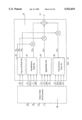
- FIG. 3 is a system block diagram of the fuzzy logic control system according to the present invention.
- FIG. 4 is a pedal force transmission diagram which shows how a thrust force is generated by a pedal force.
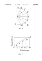
- FIGS. 5-7 show a manual torque generation curve with respect to crank arm angular position.
- FIG. 8 is a curve of the resultant torque, as a sum of manual torque and electrical torque, with respect to crank angular position.
- FIG. 9 is a fuzzy logic control algorithm that shows pre-processed input fuzzy variables and output voltage increment for motor excitation.
- FIGS. 10-12 are membership functions of related fuzzy variables in the process of fuzzification.
- FIG. 13 is a two-level fuzzy inference scheme.
- FIG. 14 is a speed curve and a resultant torque curve of an acceleration mode.
- FIGS. 15-16 are phase plane diagrams of a speed mode.
- FIG. 17 is a curve of ground friction coefficient with respect to an elebike slip.
- Table 1 shows the partition points of FIGS. 10-12.
- Table 2 shows the normalization factors of FIGS. 10-12.
- Table 3 shows the top level inference of the top level rule set shown in FIG. 13.
- Table 4 shows the acceleration rule set shown in FIG. 13.
- Table 5 shows the speed rule set shown in FIG. 13.
- Table 6 shows the deceleration rule set shown in FIG. 13.
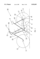
- FIG. 1 is a diagrammatic view of an elebike 30 according to the present invention.
- the elebike 30 comprises a frame assembly 10, a fork 20 installed at the front end of the frame assembly 10, a front wheel 12 rotatably installed over a front wheel shaft 11 at the lower end of the fork 20, a handle bar 21 installed at the higher end of the fork 20, a rear wheel 9 rotatably installed over a rear wheel shaft 8 at the rear end of the frame assembly 10, a seat 2 installed at a higher end of the frame assembly 10, a pedal assembly which is formed by two foot pedals 1, two crank arms 4 and a crank shaft 3, rotatably installed at a lower end of the middle portion of the frame assembly 10, a front sprocket 32 fixed to the crank shaft 3, a rear sprocket 34 connected to the rear wheel shaft 8, and a roller chain 6 installed between the front sprocket 32 and the rear sprocket 34.
- a brake 13 is installed at one end of the handle bar 21 for reducing the speed of the handle bar
- the elebike 30 comprises a nickel-hydrogen (Ni--H) battery 14 and an electrical control unit (ECU) 15 mounted on the front portion of the frame assembly 10, a servo motor 16 preferably mounted on the rear end of the frame assembly 10 for driving the rear shaft 8, a reduction gear 17 affixed to the servo motor 16 for reducing angular speed to gain more torque, and a one-way clutch 18 for applying the thrust force from the reduction gear 17 to the rear wheel shaft 8 to move the elebike 30 forward.
- the one-way clutch 18 can be changed to a two-way clutch if power braking by using the servo motor 16 is required.
- the elebike 30 further comprises a speed sensor 19 which has a magnet fixed to the rim of the front wheel 12 and a pick-up coil fixed to the front fork 20, for detecting rotation speed RPM (revolution per minute) of the front wheel 12, a brake sensor 36 installed under the brake 13 for sensing on and off of the brake 13, and a torque sensor 22 installed near the crank shaft 3 for measuring the manual torque created by a rider.
- a speed sensor 19 which has a magnet fixed to the rim of the front wheel 12 and a pick-up coil fixed to the front fork 20, for detecting rotation speed RPM (revolution per minute) of the front wheel 12, a brake sensor 36 installed under the brake 13 for sensing on and off of the brake 13, and a torque sensor 22 installed near the crank shaft 3 for measuring the manual torque created by a rider.
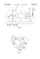
- FIG. 2 is a system block diagram of the elebike 30 shown in FIG. 1.
- the elebike 30 comprises a gear transmission 40 which is formed by the pedal assembly, the front sprocket 32, the roller chain 6 and the rear sprocket 34, for converting the pedal force created by the rider 42 over pedals 1 into manual torque ⁇ m , a sensor set 38 which is formed by the brake sensor 36, the torque sensor 22 and the speed sensor 19, an ECU 15 for collecting signal outputs from the sensor set 38 and the motor current I as inputs and generating an output signal V for controlling the servo motor 16, a servo motor 16 for converting the electrical energy stored in the battery 14 into a torque output proportional to the output signal V of the ECU 15, a reduction gear 17 and a clutch 18 for applying the torque output of the servo motor 16 to the rear wheel shaft 8.
- the electrical torque ⁇ e transmitted from the clutch 18 is coupled with the manual torque ⁇ m and becomes the resultant torque ⁇ r which is applied to the rear wheel shaft
- the ECU 15 collects the motor current I from the servo motor 16 and the following signal outputs from the sensor set 38:
- the ECU 15 When assisting a rider to drive the elebike 30, the ECU 15 will try to evaluate the rider's intention and then use the output signal V to adaptively drive the servo motor 16 to assist the rider. How to evaluate a rider's intention will be discussed below.
- the ECU 15 uses fuzzy logic to evaluate and assist a rider to reach the three working targets mentioned above, i.e. expected final speed, expected response time and riding smoothness, according to signals inputted to the ECU 15. And this will be described in FIG. 3.
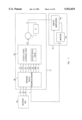
- FIG. 3 shows a system block diagram of the fuzzy logic control system of the elebike 30.
- the voltage output V of the ECU 15 is used to control the servo motor 16, and the output signals of the sensor set 38 and the motor current I are used as input signals by the ECU 15 to generate the voltage output V.
- the voltage output V of the ECU 15 represents the intended torque which should be generated by the servo motor 16.
- the servo motor 16 comprises a brushless servo torque motor 44 and a servo amplifier 46.
- the servo amplifier 46 uses the motor current I to calculate the real torque output of the servo motor 16 and compares it with the intended torque output which is calculated by using the voltage output V of the ECU 15. The difference of the comparison is then used to drive the motor 44 so that it can modify its torque output to approach the intended torque output.
- the rider 42 After applying a pedal force to a pedal 1 of the elebike 30, the rider 42 will immediately assess the speed and speed change of the elebike 30. This assessment will be used by the rider 42 to adjust the pedal force of the following steps.
- the rider 42 assesses the speed and speed change of the elebike 30 and makes the decision, the rider 42 applies a second pedal force to another pedal 1 of the elebike 30.
- the ECU 15 From the output of the torque sensor 22, the ECU 15 will observe the pedal torque ⁇ p generated by the first pedal force and its change ⁇ p from the second pedal force.
- the output of the torque sensor 22 is analogue signals which will be converted into digital signals by the ECU 15 before any calculation.
- the ECU 15 will then make a decision to assist the rider 42 by increasing the voltage output V.
- a voltage increment ⁇ will be summed up with a previous voltage output V o to drive the servo motor 16.
- the voltage increment ⁇ V is depended on the difference to the working targets. Since the output torque of the servo motor 16 is proportional to the motor current I by a torque constant Kt, the ECU 15 measures the motor current I to obtain the output torque of the servo motor 16.
- the motor current I can be measured by using a low-resistance resistor connected in series with the winding of the servo motor 16. By measuring the voltage drop across the resistor, the motor current I can be obtained by the ECU 15.
- the fuzzy logic control unit 50 of the ECU 15 collects all the aforementioned data by using a sensor data preprocessor 48 which includes the pedal torque ⁇ p and its change ⁇ p , wheel rotation speed ⁇ and its change ⁇ , motor current 1, and the brake duration T B from the brake sensor 36, the fuzzy logic control unit 50, with a plurality of fuzzy rule sets 51 stored in a non-volatile memory of the ECU 15, can generate the voltage increment ⁇ V.
- the voltage increment ⁇ V will be coupled with a previous voltage output V o stored in memory to form the output voltage V to drive the servo motor 16.
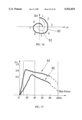
- FIG. 4 is a pedal force transmission diagram which shows how the thrust force F.sub. ⁇ is generated by the pedal force F P .
- the relationship between the pedal force F P , the torque (r 1 /r 2 ) F P l transmitted to the rear wheel shaft 8, the rotation speed ⁇ of the rear wheel 9, and the translation forward speed ⁇ of the elebike 30 is illustrated in FIG. 4 with the mathematical equations given as follows: ##EQU1## where F P : Pedal force
- the pedal torque ⁇ p is generated by the pedal tangential force multiplied by the length l of the crank arm 4. Since the pedal force F P is constantly in downward direction, it will generate a pedal torque ⁇ p of sine-wave-like curve as shown in FIG. 7.
- the shaded area in FIG. 7 encourages most of the electrical torque ⁇ e shown in FIG. 2 to be placed here in order to reduce torque ripple and make riding more smoothing. This is a way of thinking to use the complementary idea to equalize the torque curve as if it were a full wave rectifier.
- the right pedal force constructs one positive half wave while the left pedal force constructs another positive half wave. Therefore, one rotation cycle of the crank arm 4 will introduce two positive half waves.
- one mechanical crank cycle corresponds to two electrical cycles of the torque sensor 22.
- FIG. 8 An allowable working region in a figure which shows resultant torque v.s. pedal angle (or crank cycle time) of a typical elebike is illustrated in FIG. 8.
- FIG. 8 indicates a maximum manual torque curve 52 coupled with a maximum electrical torque curve 53 above the manual torque curve 52 which form a resultant torque curve 54. It is obvious that the resultant torque curve 54 is intercepted by an allowable maximum torque line 56.
- the area enclosed by A,B,C,D,E is the maximum possible area for the electrical torque to apply but subject to the constraint that the area of ABCDEF should be less than the maximum allowable speed. If the area of ABCDEF is larger than the maximum allowable speed, it is necessary to draw a set of working curves, say curve 58, curve 60, curve 62, and so on to meet the speed limit. How to select one of the working curves also depends on the satisfaction of the rider. In other word, if the rider is not satisfied with the final speed as given by the area underneath the curve 62, the fuzzy logic control unit 50 of the ECU 15 will automatically shift from the curve 62 to the curve 60 or 58.
- FIG. 9 is a fuzzy logic control algorithm that shows the pre-processed input fuzzy variables e 1 , ⁇ e 1 to e n , ⁇ e n , and output voltage increment ⁇ V for motor excitation.
- FIG. 9 shows the scheme of fuzzy processing which includes pre-processed input fuzzy variables e 1 , ⁇ e 1 to e n , ⁇ e n , from the sensor data preprocessor 48 and output voltage increment ⁇ V for motor excitation.
- the following description is applicable to each rule R 1 to R m shown in FIG. 9:
- a fuzzy variable say, wheel speed change ⁇
- the common minimum linguistic contribution value ⁇ 1 is to intercept the membership function ⁇ PS of the voltage increment ⁇ V 1 , as shown in block 64, and to find an area F 1 ( ⁇ V 1 ) bounded by that common minimum linguistic contribution value ⁇ 1 .
- the center of area is the resultant voltage increment ⁇ V that is to be summed up with the previous voltage output V o o as shown in FIG. 3.
- the resultant voltage V is the excitation to the servo motor 16.
- the fuzzy variable " ⁇ " is a motion status index for judging the status of motion dynamic which shows whether it is in acceleration, constant speed or deceleration.
- the fuzzy variable " ⁇ ” is defined as follows: ##EQU2## where ⁇ (RPS) is expressed by the number of circles per second for the wheel rotation. R G is gear ratio N 1 /N 2 of the front sprocket 32 and the rear sprocket 34, ⁇ PE (Hz) is the equivalent frequency of the pedal force F P transformed to the rear wheel shaft 8.
- fuzzy variables of the given membership functions are T B , ⁇ P , F P , ⁇ and I.
- fuzzy variables adaptive to the membership functions are ⁇ F P , ⁇ , ⁇ T B , ⁇ V, ⁇ I.
- Table 1 shows a typical way to assign the partition points.
- a calculation process is given as follows.
- the normalization factor of fuzzy variables is the possible maximum values of each fuzzy variable as found below.
- the normalization factors for all the fuzzy variables are calculated based on the following given conditions:
- N 1 44
- fuzzy rules are composed of two-level rule sets, i.e. top level rule set 70 and bottom level rule sets 72, 74 and 76 as given in FIG. 13.
- the top level rule set 70 fuzzily judges that the dynamic motion status of the elebike 30 is in acceleration, speed or deceleration.
- the bottom level rule sets comprise three rule sets, i.e. acceleration rule set 72, speed rule set 74 and deceleration rule set 76.
- the motor voltage output of each bottom level rule set i.e. ⁇ V A , ⁇ V S , ⁇ V D , is then multiplied by the weighting factor W A , W S or W D generated by the top level rule set 70.
- the motor voltage output ⁇ V is constructed by finding the union of each weighted motor voltage output.
- the top level inference in Table 3 decides the weighting of various bottom level rule sets.
- Each rule has a remark to indicate its road condition by the following notation:
- M which means motion status.
- M is defined as a vector ⁇ W A , W B , W C >.
- the sum of the three weighting factors W A , W B and W C is equal to 1.
- the vector M in Table 3 may be assigned as ⁇ 1.0,0.0,0.0> in rule 7, and ⁇ 0.9,0.1,0.0> in rule 6 and so on.
- the acceleration rule sets 72 is introduced first as follows.
- the fuzzy variable inputs of the acceleration rule set 72 include motor current I, increment of wheel rotation speed ⁇ , pedal force F P and its increment ⁇ F P .
- the output just involves the increment of voltage ⁇ V A .
- the speed curve and its acceleration curve are given in FIG. 14 that shows the degree of acceleration varies with the time.
- the acceleration rule set 72 is thus listed in Table 4. There are 18 rules that cover three cases, i.e. no aided power, paved or concrete road, and up-hill gravel road.
- the bottom level speed rule set 74 shown in Table 5 is introduced as follows.
- Average speed ⁇ AVE is monitored to find the speed error e.sub. ⁇ and ⁇ e 106 as well:
- FIGS. 15-16 show such an idea.
- the damping curves 80 and 82 shown in FIG. 16 are rider-dependent.
- the bottom level deceleration rule set 76 shown in Table 6 is finally introduced as follows .
- a slip factor S is defined as:
- ⁇ W is the target speed of the bike wheel.
- FIG. 17 shows that the maximum friction coefficient ⁇ r happens at 0.15 slip factor for curve 84 which represents a dry concrete ground condition and 0.28 slip factor for curve 86 which represents a wet paved road condition. Since maximum friction is needed while braking, the shaded area in FIG. 17 represents an appropriate control range around 0.2 slip factor.
- the control law is given as follows:
- Table 6 shows 18 rules of the deceleration rule set 76 for generating the motor voltage output ⁇ V D .
- the present invention concerning the fuzzy logic control applied to elebike control is not limited to the working model as described above. It means more modification may be made. For instance, the number of rules may be reduced or increased depending on the cost and engineering consideration. Sensors for generating the fuzzy variables may be mounted at different locations. The number of the sensors as mentioned above may be increased or reduced based on various requirements.
Landscapes
- Engineering & Computer Science (AREA)
- Chemical & Material Sciences (AREA)
- Combustion & Propulsion (AREA)
- Transportation (AREA)
- Mechanical Engineering (AREA)
- Feedback Control In General (AREA)
Abstract
Description
ΔF.sub.P +K.sub.1 ΔV.sub.A =K.sub.2 (F.sub.P +K.sub.3 I-K.sub.4 ΔΩ)
e.sub.Ω =(Ω-Ω.sub.AVE)/Ω.sub.AVE
Δe.sub.106 =ΔΩ/Ω.sub.AVE
S=(ν-ν.sub.W)/ν.sub.W
ε=(ν/ν.sub.W)-1.2=(ν/RΩ)-1.2
Δε=(Δν/ν)-(Δν.sub.W /ν.sub.W)
              TABLE 1
______________________________________
Partition points
Q.sub.1
    Q.sub.2
           Q.sub.3
                  P.sub.1
                        P.sub.2
                              P.sub.3
                                    P.sub.4
                                         P.sub.5
                                              P.sub.6
                                                   P.sub.7
______________________________________
0.2 0.5    0.8    -0.8  -0.5  -0.2  0    0.2  0.5  0.8
______________________________________
              TABLE 2
______________________________________
Normalization factors
I   Ω
           f.sub.p
                  F.sub.P
                       T.sub.B
                            ΔT.sub.B
                                  ΔF.sub.P
                                        ΔΩ
                                              ΔV
                                                   ΔI
______________________________________
6   5.3    4.6    48   1.5  1.5   24    2.56  18   3
______________________________________
              TABLE 3
______________________________________
Top level inference
        IF          THEN
Rule      φ T.sub.B     M     Remark
______________________________________
1         B     B           D     DH, B
2         B     M           D     G, B
3         B     S           S     Gr, S
4         M     M           S     C, S
5         M     S           S     P, S
6         S     M           A     Gr, A.
7         S     S           A     UH, A.
______________________________________
              TABLE 4
______________________________________
Acceleration rule set
IF                     THEN
Rule   F.sub.P
              I        ΔF.sub.P
                            ΔΩ
                                   ΔV
                                         Remark
______________________________________
 1     PS     Z        PS   PS     Z     N, 1
 2     PM     Z        PM   PM     Z     N, 2
 3     PB     Z        Z    PB     Z     N, 3
 4     PM     Z        NM   PM     Z     N, 4
 5     PS     Z        NS   PS     Z     N, 5
 6     Z      Z        Z    Z      Z     N, 6
 7     PS     Z        PS   Z      PS    P, C, 1
 8     PM     PS       PM   PS     PM    P, C, 2
 9     PB     PM       Z    PM     Z     P, C, 3
10     PS     PM       NM   PS     NS    P, C, 4
11     PS     PS       NS   PS     Z     P, C, 5
12     Z      PS       Z    Z      Z     P, C, 6
13     PM     PS       PM   Z      PM    G, U, 1
14     PB     PM       Z    PM     PM    G, U, 2
15     PB     PB       Z    PB     Z     G, U, 3
16     PM     PB       NB   PM     NM    G, U, 4
17     PS     PM       NM   PS     NS    G, U, 5
18     Z      PM       Z    Z      Z     G, U, 6
______________________________________
              TABLE 5
______________________________________
Speed rule set
        IF          THEN
Rule      e      Δe   ΔV
                                  Remark
______________________________________
1         Z      PB         NM    1
2         PM     PM         NB    2
3         PB     Z          NM    3
4         PM     NM         NS    4
5         Z      NB         PM    5
6         NS     NM         PM    6
7         NM     Z          PM    7
8         NS     PS         PS    8
______________________________________
              TABLE 6
______________________________________
Deceleration rule set
ΔT.sub.B
T.sub.B
      NB      NM    NS     Z    PS     PM   PB
______________________________________
S     Z       Z     NS     NS   NM     NM   NB
M     Z       NS    NS     NM   NM     NB   NB
B     NS      NS    NM     NM   NB     NB   NB
______________________________________
Claims (20)
Priority Applications (1)
| Application Number | Priority Date | Filing Date | Title |
|---|---|---|---|
| US08/984,369 US5922035A (en) | 1997-12-03 | 1997-12-03 | Fuzzy logic control system for electrical aided vehicle |
Applications Claiming Priority (1)
| Application Number | Priority Date | Filing Date | Title |
|---|---|---|---|
| US08/984,369 US5922035A (en) | 1997-12-03 | 1997-12-03 | Fuzzy logic control system for electrical aided vehicle |
Publications (1)
| Publication Number | Publication Date |
|---|---|
| US5922035A true US5922035A (en) | 1999-07-13 |
Family
ID=25530493
Family Applications (1)
| Application Number | Title | Priority Date | Filing Date |
|---|---|---|---|
| US08/984,369 Expired - Lifetime US5922035A (en) | 1997-12-03 | 1997-12-03 | Fuzzy logic control system for electrical aided vehicle |
Country Status (1)
| Country | Link |
|---|---|
| US (1) | US5922035A (en) |
Cited By (33)
| Publication number | Priority date | Publication date | Assignee | Title |
|---|---|---|---|---|
| US6132327A (en) * | 1998-09-09 | 2000-10-17 | Campagnolo S.R.L. | System and method for controlling a bicycle front derailleur |
| WO2001015960A1 (en) | 1999-08-31 | 2001-03-08 | Deltaglide, Inc. | Power-assist vehicle |
| US6247548B1 (en) * | 1996-05-24 | 2001-06-19 | Sony Corporation | Moving apparatus with drive power assisting device and movement controlling method |
| US6259976B1 (en) | 1999-09-25 | 2001-07-10 | Jerome H. Lemelson | Fuzzy logic based emergency flight control with thrust vectoring |
| US20020120382A1 (en) * | 2001-02-28 | 2002-08-29 | Kaoru Hatanaka | Control unit for motor-assisted bicycle |
| US6459222B1 (en) * | 1999-11-29 | 2002-10-01 | Chung Shan Institute Of Science And Technology | Bicycle control system for controlling an elebike |
| US6543799B2 (en) * | 2000-01-13 | 2003-04-08 | Shimano Inc. | Bicycle suspension |
| DE10153487A1 (en) * | 2001-10-22 | 2003-05-08 | Friedrich Graf | Controller for computer-assisted cycle, circuit has memory for storing shift programs, control device that detects rider activities with which shift programs are adapted to needs of driver |
| US6714849B1 (en) * | 1999-08-24 | 2004-03-30 | Ferrero S.P.A. | System and a method for the control of variable-ratio transmissions |
| US20060186631A1 (en) * | 2005-02-18 | 2006-08-24 | Shimano, Inc. | Bicycle control apparatus |
| CN102092441A (en) * | 2009-12-10 | 2011-06-15 | 张庆柳 | Van-type single-row seat electric car |
| EP2505477A1 (en) * | 2011-03-31 | 2012-10-03 | Honda Motor Co., Ltd. | Assistive power control apparatus for motor-assisted bicycle |
| EP2548795A1 (en) * | 2010-03-17 | 2013-01-23 | Panasonic Corporation | Method and device for controlling motor for electrically assisted bicycle |
| US20130110335A1 (en) * | 2010-05-06 | 2013-05-02 | Ivica Durdevic | Method and device for automatically controlling the gear of an electric bicycle transmission |
| US20130311020A1 (en) * | 2012-04-24 | 2013-11-21 | Modern Times Ltd. | Electrically Assisted Cycle Kit |
| CN103429490A (en) * | 2010-12-22 | 2013-12-04 | 微空间株式会社 | Motor drive control device |
| CN103569303A (en) * | 2012-07-18 | 2014-02-12 | 久鼎金属实业股份有限公司 | Booster bicycle gear shifting system with pedaling position as judgment basis |
| US20140166386A1 (en) * | 2012-12-17 | 2014-06-19 | Yamaha Hatsudoki Kabushiki Kaisha | Driving unit and battery-assisted bicycle |
| EP2582571A4 (en) * | 2010-06-17 | 2014-10-01 | Tq Systems Gmbh | Control unit for a vehicle and method for changing gears of a vehicle |
| US20140336857A1 (en) * | 2013-05-13 | 2014-11-13 | Darfon Electronics (Suzhou) Co., Ltd. | Method for automatic adjustment of pedelec |
| DE102014213504B3 (en) * | 2014-07-11 | 2015-10-15 | Robert Bosch Gmbh | Motor and / or muscle powered vehicle |
| US9162730B2 (en) | 2010-12-22 | 2015-10-20 | Microspace Corporation | Motor driving control apparatus |
| DE102014006952A1 (en) * | 2014-05-12 | 2015-11-12 | Nikolaus Michels | Drive control for light vehicles |
| EP2979968A1 (en) * | 2014-07-30 | 2016-02-03 | Daum Forschung und Entwicklung GmbH | Method for interrupting an electrical power supply of an electric motor involved in driving a bicycle , data processing program for performing such a method and bicycle comprising such a data processing program |
| US9637197B2 (en) * | 2015-07-01 | 2017-05-02 | GM Global Technology Operations LLC | Dynamic inertia compensation and pedal effort transformation for electric bike |
| CN109823453A (en) * | 2019-03-26 | 2019-05-31 | 深圳市乐骑智能科技有限公司 | A kind of scooter with gravity sensing function |
| JP2019147528A (en) * | 2018-02-28 | 2019-09-05 | ヤマハ発動機株式会社 | Assisting force calculation method for electrically assisting bicycle, control device for electrically assisting bicycle, power unit for electrically assisting bicycle, and electrically assisting bicycle |
| JP2019166912A (en) * | 2018-03-22 | 2019-10-03 | 株式会社シマノ | Human-powered vehicular control device |
| US11001337B2 (en) * | 2017-12-27 | 2021-05-11 | Shimano Inc. | Human-powered vehicle control device |
| CN113184104A (en) * | 2017-10-27 | 2021-07-30 | 株式会社岛野 | Control device for human-powered vehicle |
| CN113879446A (en) * | 2021-11-04 | 2022-01-04 | 江苏科技大学 | Electric vehicle power-assisted control method based on fuzzy technology |
| US11351872B1 (en) * | 2021-09-17 | 2022-06-07 | Euphree, Inc. | Automated acceleration with gradual reduction |
| US11840316B2 (en) | 2019-06-27 | 2023-12-12 | Shimano Inc. | Control device for human-powered vehicle |
Citations (8)
| Publication number | Priority date | Publication date | Assignee | Title |
|---|---|---|---|---|
| US4364448A (en) * | 1978-07-20 | 1982-12-21 | Yamaha Hatsudoki Kabushiki Kaisha | Speed control for wheeled vehicles |
| US5356348A (en) * | 1990-05-08 | 1994-10-18 | E.B.T., Inc. | Electronic transmission control system for a bicycle or the like |
| US5375676A (en) * | 1992-03-06 | 1994-12-27 | Yamaha Hatsudoki Kabushiki Kaisha | Bicycle with electric motor |
| US5439426A (en) * | 1992-06-12 | 1995-08-08 | Mitsubishi Jidosha Kogyo Kabushiki Kaisha | Speed change control apparatus for a vehicular automatic transmission and a troubleshooting method for operating a condition detecting device |
| US5570752A (en) * | 1993-07-26 | 1996-11-05 | Yamaha Hatsudoki Kabushiki Kaisha | Transmission arrangement for electric power assisted bicycle |
| US5758736A (en) * | 1995-03-29 | 1998-06-02 | Suzuki Kabushiki Kaisha | Power assist apparatus of power assisted bicycle |
| US5794169A (en) * | 1994-10-19 | 1998-08-11 | Hyundai Motor Company | System for determining the shift stage of an automatic transmission by using fuzzy inference to decide road gradient |
| US5845727A (en) * | 1995-06-14 | 1998-12-08 | Seiko Epson Corporation | Driving force auxiliary device |
-
1997
- 1997-12-03 US US08/984,369 patent/US5922035A/en not_active Expired - Lifetime
Patent Citations (9)
| Publication number | Priority date | Publication date | Assignee | Title |
|---|---|---|---|---|
| US4364448A (en) * | 1978-07-20 | 1982-12-21 | Yamaha Hatsudoki Kabushiki Kaisha | Speed control for wheeled vehicles |
| US5356348A (en) * | 1990-05-08 | 1994-10-18 | E.B.T., Inc. | Electronic transmission control system for a bicycle or the like |
| US5728017A (en) * | 1990-05-08 | 1998-03-17 | E.B.T., Inc. | Electronic transmission control system for a bicycle or the like |
| US5375676A (en) * | 1992-03-06 | 1994-12-27 | Yamaha Hatsudoki Kabushiki Kaisha | Bicycle with electric motor |
| US5439426A (en) * | 1992-06-12 | 1995-08-08 | Mitsubishi Jidosha Kogyo Kabushiki Kaisha | Speed change control apparatus for a vehicular automatic transmission and a troubleshooting method for operating a condition detecting device |
| US5570752A (en) * | 1993-07-26 | 1996-11-05 | Yamaha Hatsudoki Kabushiki Kaisha | Transmission arrangement for electric power assisted bicycle |
| US5794169A (en) * | 1994-10-19 | 1998-08-11 | Hyundai Motor Company | System for determining the shift stage of an automatic transmission by using fuzzy inference to decide road gradient |
| US5758736A (en) * | 1995-03-29 | 1998-06-02 | Suzuki Kabushiki Kaisha | Power assist apparatus of power assisted bicycle |
| US5845727A (en) * | 1995-06-14 | 1998-12-08 | Seiko Epson Corporation | Driving force auxiliary device |
Cited By (60)
| Publication number | Priority date | Publication date | Assignee | Title |
|---|---|---|---|---|
| US6247548B1 (en) * | 1996-05-24 | 2001-06-19 | Sony Corporation | Moving apparatus with drive power assisting device and movement controlling method |
| US6580188B2 (en) | 1996-05-24 | 2003-06-17 | Sony Corporation | Moving apparatus with drive force assist mechanism and movement control method |
| US6132327A (en) * | 1998-09-09 | 2000-10-17 | Campagnolo S.R.L. | System and method for controlling a bicycle front derailleur |
| US6714849B1 (en) * | 1999-08-24 | 2004-03-30 | Ferrero S.P.A. | System and a method for the control of variable-ratio transmissions |
| WO2001015960A1 (en) | 1999-08-31 | 2001-03-08 | Deltaglide, Inc. | Power-assist vehicle |
| EP1216184A1 (en) * | 1999-08-31 | 2002-06-26 | Deltaglide, Inc. | Power-assist vehicle |
| EP1216184B1 (en) * | 1999-08-31 | 2013-01-02 | Deltaglide, Inc. | Power-assist vehicle |
| EP2206640A3 (en) * | 1999-08-31 | 2010-10-20 | Deltaglide, Inc. | Power-assist vehicle |
| US6662086B2 (en) | 1999-09-25 | 2003-12-09 | Jerome H. Lemelson | Fuzzy logic based emergency flight control with thrust vectoring capability |
| US6259976B1 (en) | 1999-09-25 | 2001-07-10 | Jerome H. Lemelson | Fuzzy logic based emergency flight control with thrust vectoring |
| US6459222B1 (en) * | 1999-11-29 | 2002-10-01 | Chung Shan Institute Of Science And Technology | Bicycle control system for controlling an elebike |
| US6543799B2 (en) * | 2000-01-13 | 2003-04-08 | Shimano Inc. | Bicycle suspension |
| US6612599B2 (en) | 2000-01-13 | 2003-09-02 | Shimano Inc. | Bicycle suspension |
| US6595537B2 (en) | 2000-01-13 | 2003-07-22 | Shimano Inc. | Bicycle suspension |
| US6863291B2 (en) | 2000-01-13 | 2005-03-08 | Shimano, Inc. | Bicycle suspension |
| US6619684B2 (en) | 2000-01-13 | 2003-09-16 | Shimano Inc. | Bicycle suspension |
| EP1236640A3 (en) * | 2001-02-28 | 2003-09-17 | Honda Giken Kogyo Kabushiki Kaisha | Control unit for motor-assisted bicycle |
| US6957129B2 (en) | 2001-02-28 | 2005-10-18 | Honda Giken Kogyo Kabushiki Kaisha | Control unit for motor-assisted bicycle |
| US20020120382A1 (en) * | 2001-02-28 | 2002-08-29 | Kaoru Hatanaka | Control unit for motor-assisted bicycle |
| CN100491147C (en) * | 2001-02-28 | 2009-05-27 | 本田技研工业株式会社 | Control unit for moped |
| DE10153487A1 (en) * | 2001-10-22 | 2003-05-08 | Friedrich Graf | Controller for computer-assisted cycle, circuit has memory for storing shift programs, control device that detects rider activities with which shift programs are adapted to needs of driver |
| DE10153487B4 (en) * | 2001-10-22 | 2007-07-12 | Graf, Friedrich, Dipl.-Ing. (Fh) | A computerized bicycle control system and method of controlling a bicycle transmission |
| US7243937B2 (en) * | 2005-02-18 | 2007-07-17 | Shimano, Inc. | Bicycle control apparatus |
| US20060186631A1 (en) * | 2005-02-18 | 2006-08-24 | Shimano, Inc. | Bicycle control apparatus |
| CN102092441A (en) * | 2009-12-10 | 2011-06-15 | 张庆柳 | Van-type single-row seat electric car |
| CN102092441B (en) * | 2009-12-10 | 2014-03-26 | 张庆柳 | Van-type single-row seat electric car |
| EP2548795A1 (en) * | 2010-03-17 | 2013-01-23 | Panasonic Corporation | Method and device for controlling motor for electrically assisted bicycle |
| EP2548795A4 (en) * | 2010-03-17 | 2013-05-08 | Panasonic Corp | Method and device for controlling motor for electrically assisted bicycle |
| US9026288B2 (en) * | 2010-05-06 | 2015-05-05 | Robert Bosch Gmbh | Method and device for automatically controlling the gear of an electric bicycle transmission |
| US20130110335A1 (en) * | 2010-05-06 | 2013-05-02 | Ivica Durdevic | Method and device for automatically controlling the gear of an electric bicycle transmission |
| EP2582571A4 (en) * | 2010-06-17 | 2014-10-01 | Tq Systems Gmbh | Control unit for a vehicle and method for changing gears of a vehicle |
| US20140039741A1 (en) * | 2010-12-22 | 2014-02-06 | Taiyo Yuden Co., Ltd. | Motor driving control apparatus |
| CN103429490A (en) * | 2010-12-22 | 2013-12-04 | 微空间株式会社 | Motor drive control device |
| CN103429490B (en) * | 2010-12-22 | 2017-06-27 | 微空间株式会社 | Motor drive control apparatus |
| US9162730B2 (en) | 2010-12-22 | 2015-10-20 | Microspace Corporation | Motor driving control apparatus |
| US9120531B2 (en) * | 2010-12-22 | 2015-09-01 | Microspace Corporation | Motor driving control apparatus |
| EP2505477A1 (en) * | 2011-03-31 | 2012-10-03 | Honda Motor Co., Ltd. | Assistive power control apparatus for motor-assisted bicycle |
| US9272751B2 (en) * | 2012-04-24 | 2016-03-01 | Modern Times Ltd. | Electrically assisted cycle kit |
| US20130311020A1 (en) * | 2012-04-24 | 2013-11-21 | Modern Times Ltd. | Electrically Assisted Cycle Kit |
| CN103569303A (en) * | 2012-07-18 | 2014-02-12 | 久鼎金属实业股份有限公司 | Booster bicycle gear shifting system with pedaling position as judgment basis |
| CN103569303B (en) * | 2012-07-18 | 2016-04-13 | 久鼎金属实业股份有限公司 | To trample the morpet shifting system that position is judgement basis |
| US20140166386A1 (en) * | 2012-12-17 | 2014-06-19 | Yamaha Hatsudoki Kabushiki Kaisha | Driving unit and battery-assisted bicycle |
| US9199693B2 (en) * | 2012-12-17 | 2015-12-01 | Yamaha Hatsudoki Kabushiki Kaisha | Driving unit and battery-assisted bicycle |
| US20140336857A1 (en) * | 2013-05-13 | 2014-11-13 | Darfon Electronics (Suzhou) Co., Ltd. | Method for automatic adjustment of pedelec |
| US9108700B2 (en) * | 2013-05-13 | 2015-08-18 | Darfon Electronics (Suzhou) Co., Ltd. | Method for automatic adjustment of pedelec |
| DE102014006952A1 (en) * | 2014-05-12 | 2015-11-12 | Nikolaus Michels | Drive control for light vehicles |
| DE102014213504B3 (en) * | 2014-07-11 | 2015-10-15 | Robert Bosch Gmbh | Motor and / or muscle powered vehicle |
| EP2965982A1 (en) * | 2014-07-11 | 2016-01-13 | Robert Bosch Gmbh | Vehicle that can be motorised and/or powered by muscle strength |
| EP2979968A1 (en) * | 2014-07-30 | 2016-02-03 | Daum Forschung und Entwicklung GmbH | Method for interrupting an electrical power supply of an electric motor involved in driving a bicycle , data processing program for performing such a method and bicycle comprising such a data processing program |
| US9637197B2 (en) * | 2015-07-01 | 2017-05-02 | GM Global Technology Operations LLC | Dynamic inertia compensation and pedal effort transformation for electric bike |
| CN113184104A (en) * | 2017-10-27 | 2021-07-30 | 株式会社岛野 | Control device for human-powered vehicle |
| CN113184104B (en) * | 2017-10-27 | 2023-04-28 | 株式会社岛野 | Control device for manually driven vehicle |
| US11001337B2 (en) * | 2017-12-27 | 2021-05-11 | Shimano Inc. | Human-powered vehicle control device |
| JP2019147528A (en) * | 2018-02-28 | 2019-09-05 | ヤマハ発動機株式会社 | Assisting force calculation method for electrically assisting bicycle, control device for electrically assisting bicycle, power unit for electrically assisting bicycle, and electrically assisting bicycle |
| JP2019166912A (en) * | 2018-03-22 | 2019-10-03 | 株式会社シマノ | Human-powered vehicular control device |
| CN109823453A (en) * | 2019-03-26 | 2019-05-31 | 深圳市乐骑智能科技有限公司 | A kind of scooter with gravity sensing function |
| US11840316B2 (en) | 2019-06-27 | 2023-12-12 | Shimano Inc. | Control device for human-powered vehicle |
| US11351872B1 (en) * | 2021-09-17 | 2022-06-07 | Euphree, Inc. | Automated acceleration with gradual reduction |
| CN113879446A (en) * | 2021-11-04 | 2022-01-04 | 江苏科技大学 | Electric vehicle power-assisted control method based on fuzzy technology |
| CN113879446B (en) * | 2021-11-04 | 2022-10-25 | 湖南小黄鸭科技有限公司 | Electric vehicle power-assisted control method based on fuzzy technology |
Similar Documents
| Publication | Publication Date | Title |
|---|---|---|
| US5922035A (en) | Fuzzy logic control system for electrical aided vehicle | |
| US6033041A (en) | Regenerative braking control system for electric vehicle | |
| US5229955A (en) | Apparatus for detecting road surface frictional coefficient | |
| JP3675383B2 (en) | Electric vehicle regenerative braking control device | |
| CN101189141B (en) | Traction control device for vehicle | |
| US6714849B1 (en) | System and a method for the control of variable-ratio transmissions | |
| CN1629006B (en) | Vehicle drive control device | |
| JP4679779B2 (en) | Method and apparatus for determining speed variable | |
| US11701536B2 (en) | Pedal drive system | |
| JPH09267790A (en) | Regeneration control device of bicycle with auxiliary power | |
| US20040206563A1 (en) | Assist control of power assisted vehicle | |
| JP3457488B2 (en) | Automotive control device | |
| EP0554838A1 (en) | Traction control system for vehicle | |
| DE19855585A1 (en) | Light vehicle with hybrid electro-muscle power drive derives motor power control signal from pedal crank sensor signals and stored data for typical force/torque profile over crank rotation | |
| US5444625A (en) | Target slippage ratio setting device | |
| IT202000005530A1 (en) | PEDALING ASSISTANCE SYSTEM FOR ELECTRIC BICYCLE AND RELATED BICYCLE | |
| DE19949225A1 (en) | Vehicle with two or more wheels with hybrid drive of motor and muscle power drive including torque or a force sensor to determine directly the instantaneous torque of the crank or the pedal force | |
| Chen | Application of fuzzy intelligence to Elebike control design | |
| JP3054268B2 (en) | Bicycle with electric motor | |
| JP3230760B2 (en) | Bicycle with electric motor | |
| JPH06500973A (en) | Braking by deceleration control | |
| JP3036190B2 (en) | Road surface condition estimation device | |
| JPH0787644B2 (en) | Electric vehicle control device | |
| Liu et al. | A fuzzy Q-learning based assisted power management method for comfortable riding of pedelec | |
| US11787502B2 (en) | Method for controlling an electric motor of an electric bicycle for driving the electric bicycle, control unit and electric bicycle |
Legal Events
| Date | Code | Title | Description |
|---|---|---|---|
| STCF | Information on status: patent grant |
Free format text: PATENTED CASE |
|
| AS | Assignment |
Owner name: CHUNG SHAN INSTITUTE OF SCIENCE AND TECHNOLOGY, TA Free format text: ASSIGNMENT OF ASSIGNORS INTEREST;ASSIGNOR:CHEN, PING-HO;REEL/FRAME:010671/0747 Effective date: 20000307 |
|
| FPAY | Fee payment |
Year of fee payment: 4 |
|
| FEPP | Fee payment procedure |
Free format text: PAT HOLDER NO LONGER CLAIMS SMALL ENTITY STATUS, ENTITY STATUS SET TO UNDISCOUNTED (ORIGINAL EVENT CODE: STOL); ENTITY STATUS OF PATENT OWNER: LARGE ENTITY |
|
| REFU | Refund |
Free format text: REFUND - PAYMENT OF MAINTENANCE FEE, 8TH YR, SMALL ENTITY (ORIGINAL EVENT CODE: R2552); ENTITY STATUS OF PATENT OWNER: LARGE ENTITY |
|
| REFU | Refund |
Free format text: REFUND - PAYMENT OF MAINTENANCE FEE, 8TH YEAR, LARGE ENTITY (ORIGINAL EVENT CODE: R1552); ENTITY STATUS OF PATENT OWNER: LARGE ENTITY Free format text: REFUND - 7.5 YR SURCHARGE - LATE PMT W/IN 6 MO, LARGE ENTITY (ORIGINAL EVENT CODE: R1555); ENTITY STATUS OF PATENT OWNER: LARGE ENTITY |
|
| FEPP | Fee payment procedure |
Free format text: ENTITY STATUS SET TO UNDISCOUNTED (ORIGINAL EVENT CODE: BIG.); ENTITY STATUS OF PATENT OWNER: LARGE ENTITY |
|
| FPAY | Fee payment |
Year of fee payment: 8 |
|
| FPAY | Fee payment |
Year of fee payment: 12 |
|
| AS | Assignment |
Owner name: NATIONAL CHUNG SHAN INSTITUTE OF SCIENCE AND TECHN Free format text: CHANGE OF NAME;ASSIGNOR:CHUNG-SHAN INSTITUTE OF SCIENCE AND TECHNOLOGY;REEL/FRAME:035453/0240 Effective date: 20140129 |