US5920197A - Sensor for detecting the presence of a peripheral device - Google Patents
Sensor for detecting the presence of a peripheral device Download PDFInfo
- Publication number
- US5920197A US5920197A US08/512,170 US51217095A US5920197A US 5920197 A US5920197 A US 5920197A US 51217095 A US51217095 A US 51217095A US 5920197 A US5920197 A US 5920197A
- Authority
- US
- United States
- Prior art keywords
- sensor
- terminal
- information signal
- connector
- signal
- Prior art date
- Legal status (The legal status is an assumption and is not a legal conclusion. Google has not performed a legal analysis and makes no representation as to the accuracy of the status listed.)
- Expired - Lifetime
Links
Images

Classifications
-
- H—ELECTRICITY
- H01—ELECTRIC ELEMENTS
- H01R—ELECTRICALLY-CONDUCTIVE CONNECTIONS; STRUCTURAL ASSOCIATIONS OF A PLURALITY OF MUTUALLY-INSULATED ELECTRICAL CONNECTING ELEMENTS; COUPLING DEVICES; CURRENT COLLECTORS
- H01R13/00—Details of coupling devices of the kinds covered by groups H01R12/70 or H01R24/00 - H01R33/00
- H01R13/64—Means for preventing incorrect coupling
- H01R13/641—Means for preventing incorrect coupling by indicating incorrect coupling; by indicating correct or full engagement
-
- H—ELECTRICITY
- H01—ELECTRIC ELEMENTS
- H01R—ELECTRICALLY-CONDUCTIVE CONNECTIONS; STRUCTURAL ASSOCIATIONS OF A PLURALITY OF MUTUALLY-INSULATED ELECTRICAL CONNECTING ELEMENTS; COUPLING DEVICES; CURRENT COLLECTORS
- H01R13/00—Details of coupling devices of the kinds covered by groups H01R12/70 or H01R24/00 - H01R33/00
- H01R13/66—Structural association with built-in electrical component
- H01R13/70—Structural association with built-in electrical component with built-in switch
- H01R13/703—Structural association with built-in electrical component with built-in switch operated by engagement or disengagement of coupling parts, e.g. dual-continuity coupling part
Definitions
- the present invention relates to the field of electronic devices, and more particularly to physical and electrical connections between electronic devices.
- One such problem often arises when multiple display devices are connected to a single base processor within a personal computer system.
- Such a configuration might be used, for example, by a business person making an audio-visual presentation.
- one display device might reside physically near the base processor for use by the individual making the presentation, while other display devices might be situated such that the presentation may be seen by a large group of people.
- a user of a multiple-display system should not have to be concerned with how, or when, a particular display device is connected to the base system processor. Unfortunately, this is not always so, and multiple-display arrangements often lead to difficulty.
- problems can arise in the common situation in which a personal computer user interfaces with the computer by manipulating an electro-mechanical "mouse" to move a corresponding video cursor among various user-selectable menu options projected on a display device.
- a personal computer user interfaces with the computer by manipulating an electro-mechanical "mouse" to move a corresponding video cursor among various user-selectable menu options projected on a display device.
- the user may wish to "drag" an interface component, such as a menu, from one display device to another. Should a display device be disconnected from the processor while that device is actively displaying the interface component, the user may no longer be able to select menu items and the system could be inoperative. Once again, such an occurrence results in lost productivity and may constitute an unacceptable deficiency in an otherwise "user friendly" system.
- Another prior art approach uses standard connectors to detect the presence of remote audio devices, such as headphones for example.
- the audio signal is provided to one terminal of a voltage divider, causing the divider to produce a particular output voltage. If a remote devices is connected, the audio signal is disconnected from the divider, causing it to produce a different output voltage.
- the difference between these two output voltages can be sufficient to be compatible with TTL logic circuitry, e.g., it could be on the order of several volts, and thereby provide useful information to configuration software.
- this approach is not suitable for use with a signal such as a video signal, for example, which effectively comprises a somewhat random AC signal with a DC offset that causes the entire signal to be positive, e.g., the signal varies in a range of 0-2 volts. Because of the nature of this signal, the voltage divider approach does not produce a sufficiently large enough voltage swing to produce a TTL-level compatible signal.
- the present invention fulfills the above-described and other needs by providing a sensor for detecting the presence of an electronic device to which an information signal is provided.
- the sensor comprises a receiving connector which couples with, or receives, a mating connector associated with the electronic device to electrically and physically connect the device to a source of the information signal.
- the receiving connector includes a first terminal to which the information signal is applied and a second terminal that is selectively connected to the first terminal in dependence upon whether a mating connector is coupled to the receiving connector.
- the sensor also comprises a sensing circuit connected to the second terminal of the receiving connector for detecting whether the information signal is present at the second terminal.
- the sensing circuit generates a signal which indicates whether a mating connector is received within the receiving connector, and thus whether the electronic device is coupled to the information signal, in dependence upon whether the information signal is detected at the second terminal.
- the sensing circuit comprises a low-pass analog filter connected to a switching transistor for generating a signal at two logic levels. The two logic levels respectively indicate whether a mating connector is received within the receiving connector, and thus whether the electronic device is coupled to the source of the information signal.
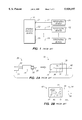
- FIG. 1 depicts a generic configuration of electronic devices as is typical in the prior art.
- FIG. 2-a shows an approximation of a standard device connector known in the prior art.
- FIG. 2-b shows an approximation of another standard device connector known in the prior art.
- FIG. 3 represents a sensor constructed in accordance with an embodiment of the present invention.
- FIG. 1 is a block diagram representing a generic arrangement of electronic devices.
- an arbitrary number of peripheral devices P1-PN are coupled with, or connected to, a general purpose device 10 by means of respective interface lines L1-LN and connectors C1-CN.
- the general purpose device 10 may be any known electronic device, for example a computer processor or a telephone switching device.
- each of the peripheral devices P1-PN may be any electronic device capable of interface with the general purpose device 10.
- the general purpose device 10 is a telephone switching device
- the peripheral devices P1-PN might be telephones or telephone answering machines.
- the peripheral devices P1-PN might be video displays, telephone modems, or data storage devices.
- each of the lines L1-LN represents the communication channel, or channels, necessary for proper interface between the general purpose device 10 and a corresponding one of the peripheral devices P1-PN.
- each of the connectors C1-CN represents the hardware necessary for coupling the general purpose device 10 to a respective one of the lines L1-LN.
- a device such as the general purpose device 10 be able to automatically detect the presence or absence of each coupled peripheral device.
- some connectors used for coupling devices are typically simple in form and standardized across industries, and redesign of such connectors for automated device detection is not practical or desirable.
- FIG. 2-a shows an approximation of a standard connector used to couple a video display device to a computer processor, or to any other video information signal source.
- a connector such as that shown in FIG. 2-a is commonly referred to in the industry as an "RCA jack” or as an "RCA" connector.
- the connector of FIG. 2-a is comprised of a male, or mating, component 20 and a female, or receiving, component 32.
- the male component 20 is comprised of a conducting tip 30, an insulator 26, a grounding band 28, a transmission wire 22, and a grounding wire 24.
- the transmission wire 22 makes electrical contact with the conducting tip 30 inside of the insulator 26.
- the grounding wire 24 makes electrical contact with the grounding band 28 inside of the insulator 26.
- the insulator 26 is constructed such that the transmission wire 22 and the conducting tip 30 remain electrically insulated from the grounding wire 24 and the grounding band 28.
- the female component 32 of the connector is comprised of a leaf contact 36, a grounding receptacle 34, a transmission wire 40, and a grounding wire 38.
- the leaf contact 36 makes electrical contact with the transmission wire 40 at an electrical terminal T4
- the grounding receptacle 34 makes electrical contact with the grounding wire 38 at an electrical terminal T5.
- the simple construction of the connector of FIG. 2-a allows for easy coupling between a video display device and a computer processor.
- the conducting tip 30 makes electrical contact with the leaf contact 36
- the grounding band 28 makes electrical contact with the grounding receptacle 34.
- a video information signal provided by a computer processor on the transmission wire 40 may be passed to a video display input connected to the transmission wire 22.
- the computer processor is electrically grounded to the grounding wire 38 and the video display device is electrically grounded to the grounding wire 24, then the computer processor and the video display device will share a common electrical ground, as is preferred for proper video transmission.
- FIG. 2-b depicts an approximation of a female component 42 of another connector that is standard in the industry.
- the male component of such a connector could be identical to that of the connector of FIG. 2-a and is not shown.
- the female component 42 also comprises parts analogous to the female component 32 of FIG. 2-a, and they are not described again here.
- the female component 42 additionally comprises a point contact 52 which makes electrical connection with a contact wire 54 at an electrical terminal T2.
- the point contact 52 makes electrical connection with the leaf contact 46 so that a signal provided on the transmission wire 50 passes through to the contact wire 54.
- a conducting tip of the male component makes contact with the leaf contact 46 and deflects the leaf contact 46 so that it ceases to make electrical connection with the point contact 52.
- a signal provided on the transmission wire 50 passes to the conducting tip of the inserted male connector component, but will not pass through to the contact wire 54.
- This type of connector is commonly used to "turn off" one device when another device is in use. For example, in an audio application, a speaker connected to the contact wire 54 receives an audio information signal applied to the transmission wire 50 so long as no male connector component is plugged into the female component 42. However, if a male connector component, perhaps associated with a set of audio headphones, is plugged into the female component 42, the speaker no longer receives the audio signal.
- video devices and computer processors may be coupled by means of very basic standardized connectors. Given the simple structure of those connectors, however, it is not possible to dedicate any one connector wire to automated device detection. Thus, it would be advantageous if automated device detection could be accomplished by means employing a standardized device connector.
- FIG. 3 depicts a device sensor constructed in accordance with an embodiment of the present invention.
- the device sensor comprises a female, or receiving, connector 42 and a sensing circuit 60.
- the receiving connector 42 is consistent with the connector of FIG. 2-b.
- an information signal such as a video signal
- a signal source such as a computer processor
- a peripheral device such as a video display
- the video signal provided on the transmission wire 50 passes to the connected peripheral device and does not pass through to the contact wire 54.
- the video signal passes through the point contact 52 to the contact wire 54.
- the sensing circuit 60 comprises an input resistor R1 which is connected at one end to the receiving connector 42 by means of the contact wire 54.
- the input resistor R1 is connected at its opposite end to a base contact B of a switching transistor Q1 to form a first node N1 of the sensing circuit 60.
- An emitter contact E of the switching transistor Q1 is connected to a supply voltage V CC , typically 5 Volts, to form a second node N2 of the sensing circuit 60.
- a collector contact C of the switching transistor Q1 is connected to a grounding resistor R3 to form a third node N3 of the sensing circuit 60.
- the grounding resistor R3 is connected at its opposite end to a circuit ground G2.
- the sensing circuit 60 also includes a pullup resistor R2 and a filtering capacitor C1 connected in parallel between the first node N1 and the second node N2. A voltage arising at the third node N3 serves as an output device indicator signal of the sensing circuit 60.
- the sensing circuit 60 In operation, the sensing circuit 60 generates the device indicator signal at two logic levels which respectively indicate whether a mating connector is received within the receiving connector 42, and therefore whether a peripheral device is present.
- the device sensor of the present invention provides automatic device detection without requiring that a specialized connector be constructed. Instead, the transmitted information signal is used to accomplish device detection.
- An information signal such as a video signal is an AC waveform in which the amplitude of the signal alternately deviates from a fixed DC offset. Therefore, when no mating connector is inserted into the receiving connector 42, the information signal is present at the contact wire 54 and a nominal voltage of R1/(R1+R2) * V CC arises at the first node N1. Because the information signal alternately deviates from its DC offset, the voltage arising at the first node N1 tends to deviate proportionally from its nominal level. However, the capacitor C1 passes any AC component arising at the first node N1 through to the second node N2 and holds the first node N1 at its nominal level.
- the pullup resistor R2 and the capacitor C1 serve as a low-pass filter, passing only a DC signal to the base contact B of the PNP-type switching transistor Q1.
- the second node N2 is also fixed at a DC level, namely V CC , by the voltage source supplying power to the sensing circuit 60.
- Resistor values R1 and R2 are readily chosen so that the nominal voltage drop from the second node N2 to the first node N1 is sufficient to forward bias an emitter-base junction E-B of the switching transistor Q1.
- resistor values R1 and R2 can easily be chosen so that the switching transistor Q1 saturates, or turns on, and allows current to flow from the second node N2 to the third node N3 through an emitter-collector junction E-C of the transistor Q1. Current then also flows through the grounding resistor R3, and because an emitter-to-collector voltage drop from the second node N2 to the third node N3 is relatively small, the third node N3 is "pulled up" to a DC level slightly less than V CC .
- V CC is typically 5 Volts
- the voltage at the third node N3 usually corresponds to a TTL logic high level.
- the sensing circuit 60 when no mating connector is inserted into the receiving connector 42, the sensing circuit 60 generates a device indicator signal at a TTL logic "one" level.
- the sensing circuit 60 When a mating connector is inserted into the receiving connector 42, the information signal passes to the connected peripheral device and does not pass through to the contact wire 54. Thus, the voltage at the first node N1 "floats up" to level V CC , and the voltage drop from the second node N2 to the first node N1 is insufficient to forward-bias the emitter-base junction E-B of the switching transistor Q1. Therefore, the switching transistor Q1 turns off, and no emitter-collector current flows from the second node N2 to the third node N3. As a result, no current flows through the grounding resistor R3, and the third node N3 "drops" to the level of the circuit ground G2, corresponding to a TTL logic low level. In sum, when a mating connector is inserted into the receiving connector 42, the sensing circuit 60 generates a device indicator signal at a TTL logic "zero" level.
- the present invention satisfies the need for a method and an apparatus by which a first device may detect the presence of a second device without requiring the use of a specialized connector.
- the present invention employs a standard-format connector in a novel way so that an existing information signal to be supplied to a peripheral device is used as an indicator of the presence or absence of that device.
- this detailed description has been developed with respect to video display devices, the present invention is readily applicable to any electronic device to which an information signal is provided. In fact, a straightforward variant of the present invention could be used to detect the presence or absence of a peripheral device transmitting, rather than receiving, an information signal.
Abstract
Description
Claims (14)
Priority Applications (1)
| Application Number | Priority Date | Filing Date | Title |
|---|---|---|---|
| US08/512,170 US5920197A (en) | 1995-08-07 | 1995-08-07 | Sensor for detecting the presence of a peripheral device |
Applications Claiming Priority (1)
| Application Number | Priority Date | Filing Date | Title |
|---|---|---|---|
| US08/512,170 US5920197A (en) | 1995-08-07 | 1995-08-07 | Sensor for detecting the presence of a peripheral device |
Publications (1)
| Publication Number | Publication Date |
|---|---|
| US5920197A true US5920197A (en) | 1999-07-06 |
Family
ID=24037987
Family Applications (1)
| Application Number | Title | Priority Date | Filing Date |
|---|---|---|---|
| US08/512,170 Expired - Lifetime US5920197A (en) | 1995-08-07 | 1995-08-07 | Sensor for detecting the presence of a peripheral device |
Country Status (1)
| Country | Link |
|---|---|
| US (1) | US5920197A (en) |
Cited By (10)
| Publication number | Priority date | Publication date | Assignee | Title |
|---|---|---|---|---|
| US6182162B1 (en) * | 1998-03-02 | 2001-01-30 | Lexar Media, Inc. | Externally coupled compact flash memory card that configures itself one of a plurality of appropriate operating protocol modes of a host computer |
| EP1096608A2 (en) * | 1999-10-25 | 2001-05-02 | Omron Corporation | Sensor system and connector used therefor |
| US6278952B1 (en) * | 1998-12-08 | 2001-08-21 | William H Swain | Reliability gage for non-contact ammeters |
| US20020112101A1 (en) * | 1998-03-02 | 2002-08-15 | Petro Estakhri | Flash memory card with enhanced operating mode detection and user-friendly interfacing system |
| US20040117798A1 (en) * | 2002-12-12 | 2004-06-17 | Xerox Corporation | Methods, apparatus, and program products for abstract applications/components in a ubiquitous computing environment |
| US6901457B1 (en) | 1998-11-04 | 2005-05-31 | Sandisk Corporation | Multiple mode communications system |
| US20050165993A1 (en) * | 2002-04-12 | 2005-07-28 | Wolfgang Gruner | Varible filed bus coupling with long coupling length, particular for mobile controllers and observation devices |
| US20080246581A1 (en) * | 2006-10-11 | 2008-10-09 | Sony Corporation | Electronic machine, connected machine identifying method for electronic machine and control system |
| US20130063126A1 (en) * | 2011-09-14 | 2013-03-14 | Hon Hai Precision Industry Co., Ltd. | Fan detecting circuit |
| US20230214344A1 (en) * | 2022-01-06 | 2023-07-06 | Dell Products L.P. | Provisioning connection information for display on cables used to couple devices |
Citations (2)
| Publication number | Priority date | Publication date | Assignee | Title |
|---|---|---|---|---|
| JPS62148866A (en) * | 1985-12-24 | 1987-07-02 | Canon Inc | Connector connection system |
| JPS63254181A (en) * | 1987-04-09 | 1988-10-20 | Kobayashi Kooc:Kk | Antioxidant composition |
-
1995
- 1995-08-07 US US08/512,170 patent/US5920197A/en not_active Expired - Lifetime
Patent Citations (2)
| Publication number | Priority date | Publication date | Assignee | Title |
|---|---|---|---|---|
| JPS62148866A (en) * | 1985-12-24 | 1987-07-02 | Canon Inc | Connector connection system |
| JPS63254181A (en) * | 1987-04-09 | 1988-10-20 | Kobayashi Kooc:Kk | Antioxidant composition |
Non-Patent Citations (1)
| Title |
|---|
| Switchcraft product reprint, from MCM Electronics, 650 Congress Park Dr., Centerville, OH 45459, catalog 29, p. 169, Jul. 1992. * |
Cited By (33)
| Publication number | Priority date | Publication date | Assignee | Title |
|---|---|---|---|---|
| US7174445B2 (en) | 1998-03-02 | 2007-02-06 | Lexar Media, Inc. | Flash memory card with enhanced operating mode detection and user-friendly interfacing system |
| US8073986B2 (en) | 1998-03-02 | 2011-12-06 | Micron Technology, Inc. | Memory devices configured to identify an operating mode |
| US7421523B2 (en) | 1998-03-02 | 2008-09-02 | Lexar Media, Inc. | Flash memory card with enhanced operating mode detection and user-friendly interfacing system |
| US6182162B1 (en) * | 1998-03-02 | 2001-01-30 | Lexar Media, Inc. | Externally coupled compact flash memory card that configures itself one of a plurality of appropriate operating protocol modes of a host computer |
| US6385667B1 (en) | 1998-03-02 | 2002-05-07 | Lexar Media, Inc. | System for configuring a flash memory card with enhanced operating mode detection and user-friendly interfacing system |
| US20020112101A1 (en) * | 1998-03-02 | 2002-08-15 | Petro Estakhri | Flash memory card with enhanced operating mode detection and user-friendly interfacing system |
| US20100228890A1 (en) * | 1998-03-02 | 2010-09-09 | Lexar Media, Inc. | Memory devices configured to identify an operating mode |
| US7721017B2 (en) | 1998-03-02 | 2010-05-18 | Lexar Media, Inc. | Methods and apparatus for identifying operating modes for peripheral devices |
| US6721819B2 (en) | 1998-03-02 | 2004-04-13 | Lexar Media, Inc. | Flash memory card with enhanced operating mode detection and user-friendly interfacing system |
| US20040039854A1 (en) * | 1998-03-02 | 2004-02-26 | Lexar Media, Inc. | Flash memory card with enhanced operating mode detection and user-friendly interfacing system |
| US20080320175A1 (en) * | 1998-03-02 | 2008-12-25 | Lexar Media, Inc. | Methods and apparatus for identifying operating modes for peripheral devices |
| US7111085B2 (en) | 1998-03-02 | 2006-09-19 | Lexar Media, Inc. | Flash memory card with enhanced operating mode detection and user-friendly interfacing system |
| US8291128B2 (en) | 1998-03-02 | 2012-10-16 | Micron Technology, Inc. | Systems configured to identify an operating mode |
| US20060085578A1 (en) * | 1998-03-02 | 2006-04-20 | Petro Hatakhri | Flash memory card with enhanced operating mode detection and user-friendly interfacing system |
| US7360003B2 (en) | 1998-11-04 | 2008-04-15 | Sandisk Corporation | Multiple mode communication system |
| US6901457B1 (en) | 1998-11-04 | 2005-05-31 | Sandisk Corporation | Multiple mode communications system |
| US6278952B1 (en) * | 1998-12-08 | 2001-08-21 | William H Swain | Reliability gage for non-contact ammeters |
| US6692311B1 (en) | 1999-10-25 | 2004-02-17 | Omron Corporation | Sensor system and connector used therefor |
| US6945828B2 (en) | 1999-10-25 | 2005-09-20 | Omron Corporation | Sensor system and connector used therefor |
| EP1096608A3 (en) * | 1999-10-25 | 2001-10-10 | Omron Corporation | Sensor system and connector used therefor |
| US20040142602A1 (en) * | 1999-10-25 | 2004-07-22 | Omron Corporation | Sensor system and connector used therefor |
| EP1096608A2 (en) * | 1999-10-25 | 2001-05-02 | Omron Corporation | Sensor system and connector used therefor |
| US20050165993A1 (en) * | 2002-04-12 | 2005-07-28 | Wolfgang Gruner | Varible filed bus coupling with long coupling length, particular for mobile controllers and observation devices |
| US7206885B2 (en) * | 2002-04-12 | 2007-04-17 | Siemens Aktiengesellschaft | Variable field bus coupling with long coupling length, particular for mobile operator control and monitoring devices |
| US20040117798A1 (en) * | 2002-12-12 | 2004-06-17 | Xerox Corporation | Methods, apparatus, and program products for abstract applications/components in a ubiquitous computing environment |
| US7620737B2 (en) * | 2002-12-12 | 2009-11-17 | Xerox Corporation | Methods, apparatus, and program products for abstract applications/components in a ubiquitous computing environment |
| US7804311B2 (en) * | 2006-10-11 | 2010-09-28 | Sony Corporation | Electronic machine, connected machine identifying method for electronic machine and control system |
| US20080246581A1 (en) * | 2006-10-11 | 2008-10-09 | Sony Corporation | Electronic machine, connected machine identifying method for electronic machine and control system |
| US20130063126A1 (en) * | 2011-09-14 | 2013-03-14 | Hon Hai Precision Industry Co., Ltd. | Fan detecting circuit |
| CN102999414A (en) * | 2011-09-14 | 2013-03-27 | 鸿富锦精密工业(深圳)有限公司 | Detecting circuit of fan |
| CN102999414B (en) * | 2011-09-14 | 2016-04-20 | 赛恩倍吉科技顾问(深圳)有限公司 | Fan circuit for detecting |
| US20230214344A1 (en) * | 2022-01-06 | 2023-07-06 | Dell Products L.P. | Provisioning connection information for display on cables used to couple devices |
| US11720514B2 (en) * | 2022-01-06 | 2023-08-08 | Dell Products L.P. | Provisioning connection information for display on cables used to couple devices |
Similar Documents
| Publication | Publication Date | Title |
|---|---|---|
| US5920197A (en) | Sensor for detecting the presence of a peripheral device | |
| CN111405453B (en) | Audio connector and circuit | |
| CN103379420B (en) | A kind of method determining earphone line sequence and electronic equipment | |
| WO2012097615A2 (en) | Multi-purpose connector for multiplexing headset interface into high definition video and audio interface and handheld electronic device | |
| WO2021135687A1 (en) | Electronic device and accessory having both quick charging function and audio transmission function | |
| US5775939A (en) | Interface assembly for peripheral accessories | |
| WO2003010619A2 (en) | Audio-video communication device for computer users | |
| US11360922B2 (en) | Three-in-one multimedia cable and electronic drawing board system | |
| US9083175B2 (en) | Protection circuit | |
| KR20200001747U (en) | Display Driver Board Card With Multiple TYPE-C Full-Featured Interfaces | |
| US6459323B2 (en) | Interface isolator and method for communication of differential digital signals | |
| JPS61502708A (en) | Audio/video adapter for audio/visual equipment | |
| CN210157357U (en) | Earphone interface module with multiplexing serial port function and mobile terminal | |
| CN102339594B (en) | Multimedia equipment | |
| GB2214039A (en) | A vertical pre-control circuit for an interface of a multi-synchronization monitor | |
| CN214412881U (en) | TypeC and HDMI two-in-one transmission display control circuit and device | |
| KR0155615B1 (en) | Synchronizing signal separation circuit of image input apparatus | |
| US7269670B2 (en) | Analog ethernet detector having first logic circuit and second logic circuit coupled to output signal detectors to determine ethernet and non-ethernet signals | |
| US20210143591A1 (en) | Data cable | |
| US3983324A (en) | Full duplex driver/receiver | |
| US20030172211A1 (en) | Dual input/output automatic selection device | |
| JPH0355995Y2 (en) | ||
| CN111277769A (en) | Switching device and image switching system and method thereof | |
| KR200228365Y1 (en) | Multimedia system with impedance matching circuit | |
| CN211580086U (en) | Host and conference system |
Legal Events
| Date | Code | Title | Description |
|---|---|---|---|
| AS | Assignment |
Owner name: APPLE COMPUTER, INC., CALIFORNIA Free format text: ASSIGNMENT OF ASSIGNORS INTEREST;ASSIGNORS:PRICE, NOAH M.;THOMPSON, LAURENCE A.;BAKER, GARY L.;REEL/FRAME:007726/0597 Effective date: 19950804 |
|
| FEPP | Fee payment procedure |
Free format text: PAYOR NUMBER ASSIGNED (ORIGINAL EVENT CODE: ASPN); ENTITY STATUS OF PATENT OWNER: LARGE ENTITY |
|
| STCF | Information on status: patent grant |
Free format text: PATENTED CASE |
|
| FPAY | Fee payment |
Year of fee payment: 4 |
|
| FPAY | Fee payment |
Year of fee payment: 8 |
|
| AS | Assignment |
Owner name: APPLE INC.,CALIFORNIA Free format text: CHANGE OF NAME;ASSIGNOR:APPLE COMPUTER, INC.;REEL/FRAME:019235/0583 Effective date: 20070109 Owner name: APPLE INC., CALIFORNIA Free format text: CHANGE OF NAME;ASSIGNOR:APPLE COMPUTER, INC.;REEL/FRAME:019235/0583 Effective date: 20070109 |
|
| FPAY | Fee payment |
Year of fee payment: 12 |