US5913074A - Buffer flow control unit for dynamically counting a number of virtual channels per service class in asynchronous transfer network - Google Patents
Buffer flow control unit for dynamically counting a number of virtual channels per service class in asynchronous transfer network Download PDFInfo
- Publication number
- US5913074A US5913074A US08/746,927 US74692796A US5913074A US 5913074 A US5913074 A US 5913074A US 74692796 A US74692796 A US 74692796A US 5913074 A US5913074 A US 5913074A
- Authority
- US
- United States
- Prior art keywords
- service class
- counter
- data
- buffer
- virtual channels
- Prior art date
- Legal status (The legal status is an assumption and is not a legal conclusion. Google has not performed a legal analysis and makes no representation as to the accuracy of the status listed.)
- Expired - Lifetime
Links
Images


Classifications
-
- H—ELECTRICITY
- H04—ELECTRIC COMMUNICATION TECHNIQUE
- H04L—TRANSMISSION OF DIGITAL INFORMATION, e.g. TELEGRAPHIC COMMUNICATION
- H04L49/00—Packet switching elements
- H04L49/25—Routing or path finding in a switch fabric
- H04L49/253—Routing or path finding in a switch fabric using establishment or release of connections between ports
- H04L49/255—Control mechanisms for ATM switching fabrics
-
- H—ELECTRICITY
- H04—ELECTRIC COMMUNICATION TECHNIQUE
- H04Q—SELECTING
- H04Q11/00—Selecting arrangements for multiplex systems
- H04Q11/04—Selecting arrangements for multiplex systems for time-division multiplexing
- H04Q11/0428—Integrated services digital network, i.e. systems for transmission of different types of digitised signals, e.g. speech, data, telecentral, television signals
- H04Q11/0478—Provisions for broadband connections
-
- H—ELECTRICITY
- H04—ELECTRIC COMMUNICATION TECHNIQUE
- H04L—TRANSMISSION OF DIGITAL INFORMATION, e.g. TELEGRAPHIC COMMUNICATION
- H04L12/00—Data switching networks
- H04L12/54—Store-and-forward switching systems
- H04L12/56—Packet switching systems
- H04L12/5601—Transfer mode dependent, e.g. ATM
- H04L2012/5638—Services, e.g. multimedia, GOS, QOS
- H04L2012/5646—Cell characteristics, e.g. loss, delay, jitter, sequence integrity
- H04L2012/5651—Priority, marking, classes
-
- H—ELECTRICITY
- H04—ELECTRIC COMMUNICATION TECHNIQUE
- H04L—TRANSMISSION OF DIGITAL INFORMATION, e.g. TELEGRAPHIC COMMUNICATION
- H04L12/00—Data switching networks
- H04L12/54—Store-and-forward switching systems
- H04L12/56—Packet switching systems
- H04L12/5601—Transfer mode dependent, e.g. ATM
- H04L2012/5678—Traffic aspects, e.g. arbitration, load balancing, smoothing, buffer management
- H04L2012/5679—Arbitration or scheduling
-
- H—ELECTRICITY
- H04—ELECTRIC COMMUNICATION TECHNIQUE
- H04L—TRANSMISSION OF DIGITAL INFORMATION, e.g. TELEGRAPHIC COMMUNICATION
- H04L12/00—Data switching networks
- H04L12/54—Store-and-forward switching systems
- H04L12/56—Packet switching systems
- H04L12/5601—Transfer mode dependent, e.g. ATM
- H04L2012/5678—Traffic aspects, e.g. arbitration, load balancing, smoothing, buffer management
- H04L2012/5681—Buffer or queue management
Definitions
- the present invention relates to an art of buffer control for fairly providing virtual channels in different service classes by a switch on Asynchronous Transfer Mode (ATM) network wherein a plural of service classes are available.
- ATM Asynchronous Transfer Mode
- One of conventional data output methods from a plural of buffers by a buffer control unit is a polling method. In this method, data is sequentially taken one by one from each buffer.
- Another conventional method is Weighted Fair Queuing (James W. Roberts, "Rate Envelope Multiplexing and Rates Sharing in B-ISDN" disclosed in Trans. Commun. Vol. E78-B, No.4 April 1995). In this method, a weighted of service is determined according to how long a packet waits in a queue.
- output from a buffer is determined regardless of the number of virtual channels in service classes that are input to each buffer.
- output from the buffer was less frequent in each virtual channel than in virtual channel in another service class.
- a buffer control unit of a node on asynchronous transfer network wherein data belonging to a plural of service classes is transferred comprising: identification means for identifying a service class of reception data; a buffer provided in each service class to which the reception data identified by the identification means is input; and control means for counting per service class number of virtual channels wherein data is being transmitted.
- output rates among buffers can be controlled based on the number of virtual channels wherein data exists in a buffer instead of the number of virtual channels wherein data is being transmitted in each service class.
- FIG. 1 is a block diagram of a first embodiment of the present invention
- FIG. 2 is a block diagram of a server control section in the first embodiment
- FIG. 3 is a flow chart of a second embodiment of the first embodiment
- FIG. 4 is a flow chart of a second embodiment of the present invention.
- FIG. 5 is a block diagram of a server control section in the second embodiment of the present invention.
- FIG. 6 is a block diagram of a third embodiment of the present invention.
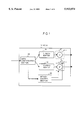
- FIG. 7 is a block diagram of a server control section of the third embodiment of the present invention.
- FIG. 1 is a block diagram showing the first embodiment of the present invention.
- the node 10 comprises the data identification section 40 for identifying the class of an input cell as class A or class B, the buffer 20 for class A, the buffer for class B, the server sections 21 and 31 for outputting a cell from each buffer, and the server control section 50 for counting the number of virtual channels wherein data of each service is being transmitted (referred to as VC, hereinafter) and controlling cell output from the server sections 21 and 31 based on the count number by the counters 21-1 and 31-1.
- VC virtual channels wherein data of each service is being transmitted
- FIG. 2 is a block diagram showing the composition of the server control section 50.
- the server control section 50 comprises the VC table write section 51 for updating the count of the cell number of the VC table when data is input to the node 10, the timer 53 provided in each VC for checking whether transmission is over, the VC table 52 for recording whether data is being transmitted in each VC, the VC number counter 54 for counting the number of VC's based on the VC table 52, and the controller section 55 for controlling cell output from the servers 21 and 31 based on the value displayed on the VC number counter.
- FIG. 3 is a flow chart showing cell output control by the server control section 50.
- the data identification section 40 identifies the class of the above-mentioned cell as class A or class B based on header information of the cell.
- the cell's arrival as well as the VC number and the result of the class identification is then notified to the server control section 50 and added to the end of the buffer in the identified class.
- the server control section 50 when the received VC in the VC table 52 is in an idle state, the state is changed to active and the VC number counter 54 increases the VC number in the VC service class by one. The timer corresponding to the VC is reset.
- the cell output is controlled by the server control section 50.
- the server control section 50 takes one cell from the class A buffer and transmits the cell.
- the value of the Greek letter ⁇ is then decreased by one and the processing in the cell output time is completed.
- the value of the Greek letter ⁇ is checked.
- the value of the Greek letter ⁇ is larger than zero, a cell is output.
- the values of the Greek letters ⁇ and ⁇ become zero when the cell is output, the value of the VC number counter 54 is set to the counters 21-1 and 31-1 to complete the processing.
- the VC number counter 54 decreases the VC number in the VC service class by one.
- the initial values of the counters 21-1 and 31-1 are set to the VC number counter 54.
- the initial values ⁇ and ⁇ of the counters 21-1 and 31-1 is multiplied by a fixed coefficient in the controller section 55 in order to weight the service rate. That is, the initial value of the service rates of each service class is calculated as follows: ⁇ , ⁇ (1- ⁇ ).
- the VC number that is being transmitted is used as the VC coefficient for determining the rate of cell output.
- the VC number wherein a cell exists in the buffer is used as the VC coefficient for determining the rate of cell output.
- FIG. 4 is a block diagram showing the second embodiment of the present invention.
- the node 10 comprises the data identification section 40 for identifying the class of an input cell as class A or class B, the buffer 20 for class A, the buffer for class B, the server sections 21 and 31 for outputting a cell from each buffer, the counters 21-1 and 31-1 in the servers, and the server control section 50 for counting the VC number in each buffer and controlling cell output from the server sections 21 and 31 based on to the count value.
- FIG. 5 is a block diagram showing the composition of the server control section 50.
- the server control section 50 comprises the VC table write section 51 for updating the count of the cell number of the VC table at every input/output to/from the buffer, the VC table 52 for managing the service class, the VC number and the cell number of each VC, the VC number counter 54 for counting the VC number wherein a cell exists in the buffer for each service class, and the controller section 55 for controlling cell output from the server 21 and 31 based on the value displayed on the VC number counter by the counters 21-1 and 31-1.
- the server control section 50 increases the cell number with the corresponding VC number in the VC table by one.
- the VC number counter 54 increases the value of the VC number counter in the corresponding class by one and when the VC number is decreased from one to zero, the VC number counter 54 decreases the value of the VC number counter in the corresponding class by one.
- a cell is output in the same way as described in the first embodiment.
- the value of the VC number counter is updated.
- FIG. 6 is a block diagram showing the third embodiment of the present invention.
- the node 10 comprises the data identification section 40 for identifying the class of an input cell as class A or class B, the buffer 20 for class A, the buffer for class B, the server sections 21 and 31 for outputting a cell from each buffer, and the server control section 50 for controlling cell output form the server sections 21 and 31.
- virtual channel wherein only the class A has the minimum guaranteed bandwidth is illustrated, and the class A server section 21 comprises the server section 21-1 for outputting a cell at the minimum guaranteed bandwidth and the server section 21-2 for outputting a cell according to the counter value.
- FIG. 7 is a block diagram showing the composition of the server control section 50.
- the server control section 50 comprises the VC table write section 51 for updating the count of the cell number in the VC table when data is input to the node 10, the timer 53 provided in each VC for checking whether transmission is over, the VC table 52 for managing the minimum guaranteed bandwidth and recording whether data is being transmitted in each VC, the VC number counter 54 for counting the VC number based on the VC table 52, the minimum guaranteed bandwidth calculation section 56 for totaling per class the minimum guaranteed bandwidths of VC's being transmitted, the scheduler 57 for setting service time for each class at the minimum guaranteed bandwidth rate, and the controller section 55 for controlling cell output from the servers 21 and 31 based on the value of the VC number counter 54 and the service time set by the scheduler 57.
- the scheduler 57 sets output time of the next cell to ((53 ⁇ 8)/minimum guaranteed bandwidth) after a cell is output from the server 21-1.
- the counters 21-1 and 31-2 in the server are set in the same way as described in the first embodiment.
- a cell is priorly output from the minimum guaranteed bandwidth and the server 21-1. That is, the controller section 50 outputs a cell from the server 21-1 at the time set by the scheduler 57. Only when no cell is output from the server 21-1, like the first and second embodiments, a cell is output from each class according to the values ⁇ and ⁇ of the VC number counter 54.
- the values ⁇ and ⁇ are managed in the same way explained in the first and second embodiments.
- each of a plural of nodes comprises different buffer per different service class, counts the VC number in the buffer and fairly offers service by changing the service rate according to the VC number.
Abstract
Description
Claims (20)
Applications Claiming Priority (2)
| Application Number | Priority Date | Filing Date | Title |
|---|---|---|---|
| JP7-300997 | 1995-11-20 | ||
| JP30099795A JP2737726B2 (en) | 1995-11-20 | 1995-11-20 | Buffer control device |
Publications (1)
| Publication Number | Publication Date |
|---|---|
| US5913074A true US5913074A (en) | 1999-06-15 |
Family
ID=17891591
Family Applications (1)
| Application Number | Title | Priority Date | Filing Date |
|---|---|---|---|
| US08/746,927 Expired - Lifetime US5913074A (en) | 1995-11-20 | 1996-11-18 | Buffer flow control unit for dynamically counting a number of virtual channels per service class in asynchronous transfer network |
Country Status (3)
| Country | Link |
|---|---|
| US (1) | US5913074A (en) |
| JP (1) | JP2737726B2 (en) |
| CA (1) | CA2190716C (en) |
Cited By (5)
| Publication number | Priority date | Publication date | Assignee | Title |
|---|---|---|---|---|
| US20010050904A1 (en) * | 2000-06-12 | 2001-12-13 | Nec Corporation | User fee charging system in which traffic is determined through sampling operation |
| US20020110137A1 (en) * | 2000-12-15 | 2002-08-15 | Xiaoning Nie | Method for timing the output of data packets from network nodes, a network node, and a network |
| US6738385B1 (en) * | 1998-09-02 | 2004-05-18 | Nec Corporation | ATM cell buffer read control system and control method |
| US20050078695A1 (en) * | 2003-06-27 | 2005-04-14 | Broadcom Corporation | Dynamically shared memory |
| WO2011143094A3 (en) * | 2010-05-09 | 2012-02-23 | Citrix Systems, Inc. | Systems and methods for allocation of classes of service to network connections corresponding to virtual channels |
Families Citing this family (3)
| Publication number | Priority date | Publication date | Assignee | Title |
|---|---|---|---|---|
| JP3077677B2 (en) * | 1998-07-14 | 2000-08-14 | 日本電気株式会社 | Quality assurance node equipment |
| JP3415620B2 (en) * | 2001-02-22 | 2003-06-09 | 株式会社アジア・インターネット・ホールディング | Communication system, communication management system between networks, method for managing communication between networks, program, and recording medium |
| JP5655484B2 (en) * | 2010-10-07 | 2015-01-21 | 富士通株式会社 | Packet transmission device, signal termination device, communication system, and communication method |
Citations (7)
| Publication number | Priority date | Publication date | Assignee | Title |
|---|---|---|---|---|
| US5455825A (en) * | 1994-04-28 | 1995-10-03 | Mitsubishi Electric Research Laboratories | Tag-based scheduling system for digital communication switch |
| US5511177A (en) * | 1991-11-21 | 1996-04-23 | Hitachi, Ltd. | File data multiplexing method and data processing system |
| US5515359A (en) * | 1994-08-26 | 1996-05-07 | Mitsubishi Electric Research Laboratories, Inc. | Credit enhanced proportional rate control system |
| US5539747A (en) * | 1993-08-24 | 1996-07-23 | Matsushita Electric Industrial Co., Ltd. | Flow control method |
| US5555265A (en) * | 1994-02-28 | 1996-09-10 | Fujitsu Limited | Switching path setting system used in switching equipment for exchanging a fixed length cell |
| US5633859A (en) * | 1994-09-16 | 1997-05-27 | The Ohio State University | Method and apparatus for congestion management in computer networks using explicit rate indication |
| US5737315A (en) * | 1994-03-16 | 1998-04-07 | Fujitsu Limited | Traffic control device in private ATM network |
-
1995
- 1995-11-20 JP JP30099795A patent/JP2737726B2/en not_active Expired - Lifetime
-
1996
- 1996-11-18 US US08/746,927 patent/US5913074A/en not_active Expired - Lifetime
- 1996-11-19 CA CA 2190716 patent/CA2190716C/en not_active Expired - Fee Related
Patent Citations (7)
| Publication number | Priority date | Publication date | Assignee | Title |
|---|---|---|---|---|
| US5511177A (en) * | 1991-11-21 | 1996-04-23 | Hitachi, Ltd. | File data multiplexing method and data processing system |
| US5539747A (en) * | 1993-08-24 | 1996-07-23 | Matsushita Electric Industrial Co., Ltd. | Flow control method |
| US5555265A (en) * | 1994-02-28 | 1996-09-10 | Fujitsu Limited | Switching path setting system used in switching equipment for exchanging a fixed length cell |
| US5737315A (en) * | 1994-03-16 | 1998-04-07 | Fujitsu Limited | Traffic control device in private ATM network |
| US5455825A (en) * | 1994-04-28 | 1995-10-03 | Mitsubishi Electric Research Laboratories | Tag-based scheduling system for digital communication switch |
| US5515359A (en) * | 1994-08-26 | 1996-05-07 | Mitsubishi Electric Research Laboratories, Inc. | Credit enhanced proportional rate control system |
| US5633859A (en) * | 1994-09-16 | 1997-05-27 | The Ohio State University | Method and apparatus for congestion management in computer networks using explicit rate indication |
Non-Patent Citations (4)
| Title |
|---|
| J.W. Roberts, "Rate Envelope Multiplexing and Rate Sharing in B-ISDN", IEICE Trans. Commun., vol. E78-B, No. 4, Apr. 1995, pp. 431-438. |
| J.W. Roberts, Rate Envelope Multiplexing and Rate Sharing in B ISDN , IEICE Trans. Commun., vol. E78 B, No. 4, Apr. 1995, pp. 431 438. * |
| R. Fan, et al., "Expandable ATOM Switch Architecture (XATOM) for ATM LANS", Reprinted from 1994 IEEE International Conference on Communications, May 1-5, 1994, pp. 402-409. |
| R. Fan, et al., Expandable ATOM Switch Architecture (XATOM) for ATM LANS , Reprinted from 1994 IEEE International Conference on Communications, May 1 5, 1994, pp. 402 409. * |
Cited By (10)
| Publication number | Priority date | Publication date | Assignee | Title |
|---|---|---|---|---|
| US6738385B1 (en) * | 1998-09-02 | 2004-05-18 | Nec Corporation | ATM cell buffer read control system and control method |
| US20010050904A1 (en) * | 2000-06-12 | 2001-12-13 | Nec Corporation | User fee charging system in which traffic is determined through sampling operation |
| US6973046B2 (en) * | 2000-06-12 | 2005-12-06 | Nec Corporation | User fee charging system in which traffic is determined through sampling operation |
| US20020110137A1 (en) * | 2000-12-15 | 2002-08-15 | Xiaoning Nie | Method for timing the output of data packets from network nodes, a network node, and a network |
| US7130269B2 (en) * | 2000-12-15 | 2006-10-31 | Infineon Technologies Ag | Method for timing the output of data packets from network nodes, a network node, and a network |
| US20050078695A1 (en) * | 2003-06-27 | 2005-04-14 | Broadcom Corporation | Dynamically shared memory |
| US7284076B2 (en) * | 2003-06-27 | 2007-10-16 | Broadcom Corporation | Dynamically shared memory |
| WO2011143094A3 (en) * | 2010-05-09 | 2012-02-23 | Citrix Systems, Inc. | Systems and methods for allocation of classes of service to network connections corresponding to virtual channels |
| US9288137B2 (en) | 2010-05-09 | 2016-03-15 | Citrix Systems, Inc. | Systems and methods for allocation of classes of service to network connections corresponding to virtual channels |
| US9813346B2 (en) | 2010-05-09 | 2017-11-07 | Citrix Systems, Inc. | Systems and methods for allocation of classes of service to network connections corresponding to virtual channels |
Also Published As
| Publication number | Publication date |
|---|---|
| JP2737726B2 (en) | 1998-04-08 |
| CA2190716C (en) | 2000-08-08 |
| JPH09149035A (en) | 1997-06-06 |
| CA2190716A1 (en) | 1997-05-21 |
Similar Documents
| Publication | Publication Date | Title |
|---|---|---|
| US5793747A (en) | Event-driven cell scheduler and method for supporting multiple service categories in a communication network | |
| US5267232A (en) | Method of controlling data transmission in ATM network with cell loss priority level | |
| US5822540A (en) | Method and apparatus for discarding frames in a communications device | |
| US5859835A (en) | Traffic scheduling system and method for packet-switched networks | |
| EP0763915B1 (en) | Packet transfer device and method adaptive to a large number of input ports | |
| US6661802B1 (en) | Congestion management | |
| US6430156B1 (en) | Traffic control method for providing predictive guaranteed service | |
| JPH07183888A (en) | Atm multiplexing control system | |
| US6526062B1 (en) | System and method for scheduling and rescheduling the transmission of cell objects of different traffic types | |
| US6928054B1 (en) | Apparatus, method, media and signals for connection-class parameter control of packet flow | |
| US6108303A (en) | Method and apparatus for traffic control in a cell-based network | |
| US5913074A (en) | Buffer flow control unit for dynamically counting a number of virtual channels per service class in asynchronous transfer network | |
| US6944182B1 (en) | ATM cell conversion circuit and ATM cell conversion method | |
| EP1031253B1 (en) | Buffer management method | |
| US7130270B2 (en) | Method and apparatus for varying bandwidth provided to virtual channels in a virtual path | |
| US7304945B1 (en) | Method and apparatus for dynamic bitmap generator scheduler | |
| JP3443531B2 (en) | Communication simulation device | |
| US7133932B2 (en) | Scheduling system using packet FIFOs and cell FIFOs for converting IP packets to ATM cells | |
| US20030007494A1 (en) | Method and apparatus for a traffic shaper | |
| JP2855485B2 (en) | Traffic observation circuit | |
| JP2862709B2 (en) | Bandwidth control device and bandwidth control method in ATM network | |
| US20060126550A1 (en) | Data switch and a method for broadcast packet queue estimation | |
| JP3165852B2 (en) | Traffic observation device | |
| JP3051101B2 (en) | Cell buffer device and selective ATM cell discarding method | |
| JP2899609B2 (en) | Cell sending device |
Legal Events
| Date | Code | Title | Description |
|---|---|---|---|
| AS | Assignment |
Owner name: NEC CORPORATION, A CORPORATION OF JAPAN, JAPAN Free format text: ASSIGNMENT OF ASSIGNORS INTEREST;ASSIGNORS:IKEDA, CHINATSU;FAN, RUIXUE;REEL/FRAME:008325/0990 Effective date: 19961213 |
|
| FEPP | Fee payment procedure |
Free format text: PAYOR NUMBER ASSIGNED (ORIGINAL EVENT CODE: ASPN); ENTITY STATUS OF PATENT OWNER: LARGE ENTITY |
|
| STCF | Information on status: patent grant |
Free format text: PATENTED CASE |
|
| FPAY | Fee payment |
Year of fee payment: 4 |
|
| AS | Assignment |
Owner name: JUNIPER NETWORKS, INC., CALIFORNIA Free format text: ASSIGNMENT OF ASSIGNORS INTEREST;ASSIGNOR:NEC CORPORATION;REEL/FRAME:016274/0345 Effective date: 20050117 |
|
| FEPP | Fee payment procedure |
Free format text: PAYER NUMBER DE-ASSIGNED (ORIGINAL EVENT CODE: RMPN); ENTITY STATUS OF PATENT OWNER: LARGE ENTITY Free format text: PAYOR NUMBER ASSIGNED (ORIGINAL EVENT CODE: ASPN); ENTITY STATUS OF PATENT OWNER: LARGE ENTITY |
|
| FPAY | Fee payment |
Year of fee payment: 8 |
|
| FPAY | Fee payment |
Year of fee payment: 12 |