US5898520A - Three-dimensional imaging system having a polarizing filter - Google Patents
Three-dimensional imaging system having a polarizing filter Download PDFInfo
- Publication number
- US5898520A US5898520A US08/798,235 US79823597A US5898520A US 5898520 A US5898520 A US 5898520A US 79823597 A US79823597 A US 79823597A US 5898520 A US5898520 A US 5898520A
- Authority
- US
- United States
- Prior art keywords
- polarizing
- plane
- polarizer
- layer
- liquid crystal
- Prior art date
- Legal status (The legal status is an assumption and is not a legal conclusion. Google has not performed a legal analysis and makes no representation as to the accuracy of the status listed.)
- Expired - Lifetime
Links
Images
Classifications
-
- G—PHYSICS
- G02—OPTICS
- G02B—OPTICAL ELEMENTS, SYSTEMS OR APPARATUS
- G02B30/00—Optical systems or apparatus for producing three-dimensional [3D] effects, e.g. stereoscopic images
- G02B30/20—Optical systems or apparatus for producing three-dimensional [3D] effects, e.g. stereoscopic images by providing first and second parallax images to an observer's left and right eyes
- G02B30/22—Optical systems or apparatus for producing three-dimensional [3D] effects, e.g. stereoscopic images by providing first and second parallax images to an observer's left and right eyes of the stereoscopic type
- G02B30/25—Optical systems or apparatus for producing three-dimensional [3D] effects, e.g. stereoscopic images by providing first and second parallax images to an observer's left and right eyes of the stereoscopic type using polarisation techniques
-
- G—PHYSICS
- G03—PHOTOGRAPHY; CINEMATOGRAPHY; ANALOGOUS TECHNIQUES USING WAVES OTHER THAN OPTICAL WAVES; ELECTROGRAPHY; HOLOGRAPHY
- G03B—APPARATUS OR ARRANGEMENTS FOR TAKING PHOTOGRAPHS OR FOR PROJECTING OR VIEWING THEM; APPARATUS OR ARRANGEMENTS EMPLOYING ANALOGOUS TECHNIQUES USING WAVES OTHER THAN OPTICAL WAVES; ACCESSORIES THEREFOR
- G03B35/00—Stereoscopic photography
- G03B35/16—Stereoscopic photography by sequential viewing
-
- H—ELECTRICITY
- H04—ELECTRIC COMMUNICATION TECHNIQUE
- H04N—PICTORIAL COMMUNICATION, e.g. TELEVISION
- H04N13/00—Stereoscopic video systems; Multi-view video systems; Details thereof
- H04N13/30—Image reproducers
- H04N13/332—Displays for viewing with the aid of special glasses or head-mounted displays [HMD]
- H04N13/337—Displays for viewing with the aid of special glasses or head-mounted displays [HMD] using polarisation multiplexing
-
- H—ELECTRICITY
- H04—ELECTRIC COMMUNICATION TECHNIQUE
- H04N—PICTORIAL COMMUNICATION, e.g. TELEVISION
- H04N13/00—Stereoscopic video systems; Multi-view video systems; Details thereof
- H04N13/30—Image reproducers
- H04N13/332—Displays for viewing with the aid of special glasses or head-mounted displays [HMD]
- H04N13/344—Displays for viewing with the aid of special glasses or head-mounted displays [HMD] with head-mounted left-right displays
-
- H—ELECTRICITY
- H04—ELECTRIC COMMUNICATION TECHNIQUE
- H04N—PICTORIAL COMMUNICATION, e.g. TELEVISION
- H04N13/00—Stereoscopic video systems; Multi-view video systems; Details thereof
- H04N13/30—Image reproducers
- H04N13/363—Image reproducers using image projection screens
-
- H—ELECTRICITY
- H04—ELECTRIC COMMUNICATION TECHNIQUE
- H04N—PICTORIAL COMMUNICATION, e.g. TELEVISION
- H04N13/00—Stereoscopic video systems; Multi-view video systems; Details thereof
- H04N13/10—Processing, recording or transmission of stereoscopic or multi-view image signals
- H04N13/189—Recording image signals; Reproducing recorded image signals
-
- H—ELECTRICITY
- H04—ELECTRIC COMMUNICATION TECHNIQUE
- H04N—PICTORIAL COMMUNICATION, e.g. TELEVISION
- H04N13/00—Stereoscopic video systems; Multi-view video systems; Details thereof
- H04N13/20—Image signal generators
- H04N13/286—Image signal generators having separate monoscopic and stereoscopic modes
-
- H—ELECTRICITY
- H04—ELECTRIC COMMUNICATION TECHNIQUE
- H04N—PICTORIAL COMMUNICATION, e.g. TELEVISION
- H04N13/00—Stereoscopic video systems; Multi-view video systems; Details thereof
- H04N13/30—Image reproducers
- H04N13/332—Displays for viewing with the aid of special glasses or head-mounted displays [HMD]
- H04N13/341—Displays for viewing with the aid of special glasses or head-mounted displays [HMD] using temporal multiplexing
-
- H—ELECTRICITY
- H04—ELECTRIC COMMUNICATION TECHNIQUE
- H04N—PICTORIAL COMMUNICATION, e.g. TELEVISION
- H04N13/00—Stereoscopic video systems; Multi-view video systems; Details thereof
- H04N13/30—Image reproducers
- H04N13/398—Synchronisation thereof; Control thereof
-
- H—ELECTRICITY
- H04—ELECTRIC COMMUNICATION TECHNIQUE
- H04N—PICTORIAL COMMUNICATION, e.g. TELEVISION
- H04N19/00—Methods or arrangements for coding, decoding, compressing or decompressing digital video signals
- H04N19/50—Methods or arrangements for coding, decoding, compressing or decompressing digital video signals using predictive coding
- H04N19/597—Methods or arrangements for coding, decoding, compressing or decompressing digital video signals using predictive coding specially adapted for multi-view video sequence encoding
Definitions
- This invention relates to imaging systems. Specifically, the present invention relates to three-dimensional imaging systems for use with passive polarizing glasses.
- Three-dimensional stereovision imaging systems are used in a variety of demanding applications ranging from aircraft head-up displays to virtual reality and TV and/or computer monitor applications. These applications require realistic images that appear three-dimensional.
- Stereovision imaging systems typically include a display device for producing alternate left-eye, right-eye images. Each eye perceives a slightly different image adjusted for the difference in viewing angles between the left and right eyes. This enhances depth perception, making images appear more realistic.
- the inventive system is adapted for use with a polarizing filter and includes an imaging subsystem for generating alternating left and right images.
- a linear polarizer near the image plane polarizes electromagnetic energy corresponding to the image plane and provides a polarized image in response thereto.
- An electrically addressed twist liquid crystal screen rotates the plane of oscillation of the polarized image by a first twist angle at predetermined times synchronized with the alternating left and right images.
- Polarizing glasses direct the polarized image from the twist liquid crystal into alternate eyes at the predetermined times in response to the polarization state of the polarized image.
- the polarizing glasses have first and second eye-pieces having first and second linear polarizers respectively.
- the polarizing plane of the first polarizer is rotated with respect to the polarizing plane of the second polarizer by an angle equivalent to the twist angle which is ninety-degrees.
- the polarizing filter includes a scattering screen for reflective mode operation, and a display for transmissive mode operation.
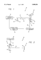
- FIG. 1 is a diagram of a three-dimensional imaging system operating in reflecting mode, including a polarizing filter, and constructed in accordance with the teachings of the present invention.
- FIG. 2 is a diagram of an alternative embodiment of the present invention including a polarizing filter operating in transmitting mode.
- FIG. 1 is a diagram of a three-dimensional imaging system 20 operating in reflecting mode, including a polarizing filter 22, and constructed in accordance with the teachings of the present invention.
- the imaging system 20 includes a conventional stereovision projector 24 that projects an unpolarized beam 26 of alternate left and right images.
- An inventive polarizing filter 22 is placed with respect to the projector 24 so that the beam 26 impinges on the filter 22 with a small angle of incidence.
- the polarizing filter 22 includes a twist liquid crystal (TLC) layer 28 adjacent to a polarizer sheet 30 that is in turn adjacent to a scattering screen 32. Twist liquid crystal material is known in the art.
- TLC twist liquid crystal
- the unpolarized stereo projection beam 26 passes through the TLC layer 28 unaffected by the state of the layer 28.
- the beam 26 then passes through the polarizer sheet 30 and reflects off the scattering screen 32 adjacent to the polarizer sheet 30 as a reflected beam 34.
- the reflected beam 34 is linearly polarized by the polarizer sheet 30 and has a first plane of oscillation (not shown).
- the reflected beam 34 passes through the TLC layer 28 where the plane of oscillation is selectively twisted by the TLC layer 28 resulting in an alternately polarized beam 40.
- a twist liquid crystal controller 36 is connected to the TLC layer 28 via a bus 38 and controls the twisting of the plane of oscillation of the reflected beam 34 by the layer 28 by selectively activating the layer 28.
- the TLC controller 36 includes a synchronizing circuit 39 that synchronizes the twisting of the plane of oscillation of the beam 34 with the alternation of the left and right image data from the projector 24.
- TLC controllers 36 including universal interfaces and stereoscopic computer software, have been marketed that may be used for synchronizing the polarizing filter 22 with alternate images.
- 3000 Stereo-Driver from 3DTV Corp. may be used for this purpose.
- the twisting of the plane of oscillation of the reflected beam 34 is synchronized with the alternate left and right images in the incident beam 26.
- Image data in the image beam 34 is polarized so that it has the first plane of oscillation.
- the plane of oscillation of right image data in the alternately polarized beam 40 is twisted so that it has a second plane of oscillation.
- the left image data remains untwisted.
- the first plane of oscillation is angled with respect to the second plane of oscillation by ninety degrees and is parallel (p-polarization) to plane of polarization (not shown) of the polarizer sheet 30.
- Right image data is twisted by the TLC layer 28 so that its plane of oscillation is perpendicular (s-polarization) to the plane of polarization of the polarizer sheet 30.
- the alternately polarized beam 40 exits the TLC Layer 28 having p and s polarizations for left and right image data respectively.
- Image information in the alternately polarized beam 40 may be viewed with a pair of polarized glasses 42.
- the glasses have a p-polarized eye-piece 44 and a s-polarized eye-piece 46 that cover left and right eyes respectively.
- the s-polarized eye-piece 46 allows s-polarized light corresponding to right image data to pass through the eye-piece 46. Left image data is blocked by the s-polarized eye-piece 46.
- the p-polarized eye-piece 44 allows left image data to pass through the eye-piece 44 and blocks right image data. Hence, left and right eyes receive left and right image data respectively regardless of the viewing angle.
- the polarizing filter 22 has a multilayer configuration including a polarizing sheet and a single cell or multiple cells of Twisted-Nematic Liquid-Crystal such as may be obtained from Hughes Research Laboratories in Malibu, Calif.
- the single or multi-cell is placed over the scattering screen or monitor.
- FIG. 2 is a diagram of an alternative embodiment 50 of the present invention including a polarizing filter 48 operating in transmitting mode.
- the polarizing filter 48 of the system 50 includes a display device 52 for transmitting alternate left and right images 54 through the polarizer sheet 30 and the TLC layer 28.
- the alternate images 54 in the form of electromagnetic energy are linearly polarized by the polarizer sheet 30 before passing through the TLC layer 28.
- the operation of the TLC layer 28 in the transmitting system 50 is similar to the operation of the TLC layer 28 in the reflecting system 20 of FIG. 1.
- the TLC layer 28 selectively rotates the plane of oscillation of polarized electromagnetic energy corresponding to the images 54.
- the operation of the glasses 42 in the transmitting system 50 is also similar to the operation of the glasses 42 in the reflecting system 20 of FIG. 1.
- the glasses 42 direct a beam of alternately polarized images into alternate eyes via the alternately polarized eye-pieces 44, 46.
Abstract
Description
Claims (4)
Priority Applications (1)
| Application Number | Priority Date | Filing Date | Title |
|---|---|---|---|
| US08/798,235 US5898520A (en) | 1997-02-11 | 1997-02-11 | Three-dimensional imaging system having a polarizing filter |
Applications Claiming Priority (1)
| Application Number | Priority Date | Filing Date | Title |
|---|---|---|---|
| US08/798,235 US5898520A (en) | 1997-02-11 | 1997-02-11 | Three-dimensional imaging system having a polarizing filter |
Publications (1)
| Publication Number | Publication Date |
|---|---|
| US5898520A true US5898520A (en) | 1999-04-27 |
Family
ID=25172876
Family Applications (1)
| Application Number | Title | Priority Date | Filing Date |
|---|---|---|---|
| US08/798,235 Expired - Lifetime US5898520A (en) | 1997-02-11 | 1997-02-11 | Three-dimensional imaging system having a polarizing filter |
Country Status (1)
| Country | Link |
|---|---|
| US (1) | US5898520A (en) |
Cited By (9)
| Publication number | Priority date | Publication date | Assignee | Title |
|---|---|---|---|---|
| DE10034837A1 (en) * | 2000-07-18 | 2002-02-21 | Vision Drei Ges Fuer Audiovisu | Stereoscopic image projection system has switched polarization glasses stops scintillation |
| US20070043466A1 (en) * | 2005-08-18 | 2007-02-22 | Vesely Michael A | Stereoscopic display using polarized eyewear |
| US20070040905A1 (en) * | 2005-08-18 | 2007-02-22 | Vesely Michael A | Stereoscopic display using polarized eyewear |
| US20090141022A1 (en) * | 2007-11-24 | 2009-06-04 | Tom Kimpe | Sensory unit for a 3-dimensional display |
| CN101790062A (en) * | 2010-03-25 | 2010-07-28 | 河北工业大学 | Stereoprojection device of single projector with single liquid crystal light valve |
| CN101806995A (en) * | 2010-03-25 | 2010-08-18 | 河北工业大学 | Three-dimensional projecting apparatus with double liquid crystal light valves and single projector |
| US20130201325A1 (en) * | 2012-02-08 | 2013-08-08 | Apple Inc. | Shape reflector and surface contour mapping |
| US9545188B2 (en) | 2010-12-02 | 2017-01-17 | Ultradent Products, Inc. | System and method of viewing and tracking stereoscopic video images |
| US10021351B2 (en) | 2012-06-01 | 2018-07-10 | Ultradent Products, Inc. | Stereoscopic video imaging |
Citations (8)
| Publication number | Priority date | Publication date | Assignee | Title |
|---|---|---|---|---|
| US3858001A (en) * | 1973-05-11 | 1974-12-31 | Honeywell Inc | Stereoscopic display system |
| US3960438A (en) * | 1972-12-01 | 1976-06-01 | Honeywell Inc. | Reflective displays |
| GB1523436A (en) * | 1975-10-24 | 1978-08-31 | Secr Defence | Three dimensional display system |
| US4281341A (en) * | 1978-11-09 | 1981-07-28 | The Marconi Company Limited | Stereoscopic television system |
| US4719507A (en) * | 1985-04-26 | 1988-01-12 | Tektronix, Inc. | Stereoscopic imaging system with passive viewing apparatus |
| US4792850A (en) * | 1987-11-25 | 1988-12-20 | Sterographics Corporation | Method and system employing a push-pull liquid crystal modulator |
| US4870486A (en) * | 1986-02-17 | 1989-09-26 | Sharp Kabushiki Kaisha | Virtual stereographic display system |
| US4877307A (en) * | 1988-07-05 | 1989-10-31 | Kaiser Aerospace & Electronics Corporation | Stereoscopic display |
-
1997
- 1997-02-11 US US08/798,235 patent/US5898520A/en not_active Expired - Lifetime
Patent Citations (8)
| Publication number | Priority date | Publication date | Assignee | Title |
|---|---|---|---|---|
| US3960438A (en) * | 1972-12-01 | 1976-06-01 | Honeywell Inc. | Reflective displays |
| US3858001A (en) * | 1973-05-11 | 1974-12-31 | Honeywell Inc | Stereoscopic display system |
| GB1523436A (en) * | 1975-10-24 | 1978-08-31 | Secr Defence | Three dimensional display system |
| US4281341A (en) * | 1978-11-09 | 1981-07-28 | The Marconi Company Limited | Stereoscopic television system |
| US4719507A (en) * | 1985-04-26 | 1988-01-12 | Tektronix, Inc. | Stereoscopic imaging system with passive viewing apparatus |
| US4870486A (en) * | 1986-02-17 | 1989-09-26 | Sharp Kabushiki Kaisha | Virtual stereographic display system |
| US4792850A (en) * | 1987-11-25 | 1988-12-20 | Sterographics Corporation | Method and system employing a push-pull liquid crystal modulator |
| US4877307A (en) * | 1988-07-05 | 1989-10-31 | Kaiser Aerospace & Electronics Corporation | Stereoscopic display |
Cited By (15)
| Publication number | Priority date | Publication date | Assignee | Title |
|---|---|---|---|---|
| DE10034837A1 (en) * | 2000-07-18 | 2002-02-21 | Vision Drei Ges Fuer Audiovisu | Stereoscopic image projection system has switched polarization glasses stops scintillation |
| US20070043466A1 (en) * | 2005-08-18 | 2007-02-22 | Vesely Michael A | Stereoscopic display using polarized eyewear |
| US20070040905A1 (en) * | 2005-08-18 | 2007-02-22 | Vesely Michael A | Stereoscopic display using polarized eyewear |
| US9225949B2 (en) * | 2007-11-24 | 2015-12-29 | Barco, N.V. | Sensory unit for a 3-dimensional display |
| US20090141022A1 (en) * | 2007-11-24 | 2009-06-04 | Tom Kimpe | Sensory unit for a 3-dimensional display |
| CN101790062A (en) * | 2010-03-25 | 2010-07-28 | 河北工业大学 | Stereoprojection device of single projector with single liquid crystal light valve |
| CN101806995A (en) * | 2010-03-25 | 2010-08-18 | 河北工业大学 | Three-dimensional projecting apparatus with double liquid crystal light valves and single projector |
| CN101790062B (en) * | 2010-03-25 | 2013-05-08 | 深圳市时代华影科技开发有限公司 | Stereoprojection device of single projector with single liquid crystal light valve |
| US9545188B2 (en) | 2010-12-02 | 2017-01-17 | Ultradent Products, Inc. | System and method of viewing and tracking stereoscopic video images |
| US10154775B2 (en) | 2010-12-02 | 2018-12-18 | Ultradent Products, Inc. | Stereoscopic video imaging and tracking system |
| US10716460B2 (en) | 2010-12-02 | 2020-07-21 | Ultradent Products, Inc. | Stereoscopic video imaging and tracking system |
| US20130201325A1 (en) * | 2012-02-08 | 2013-08-08 | Apple Inc. | Shape reflector and surface contour mapping |
| US9186470B2 (en) * | 2012-02-08 | 2015-11-17 | Apple Inc. | Shape reflector and surface contour mapping |
| US10021351B2 (en) | 2012-06-01 | 2018-07-10 | Ultradent Products, Inc. | Stereoscopic video imaging |
| US11856178B2 (en) | 2012-06-01 | 2023-12-26 | Ultradent Products, Inc. | Stereoscopic video imaging |
Similar Documents
| Publication | Publication Date | Title |
|---|---|---|
| EP0349692B1 (en) | Stereoscopic display | |
| EP1950980B1 (en) | Autostereoscopic 2D/3D switchable display apparatus with high light efficiency, employing a lenticular screen and time-multiplexing of 3D-views | |
| US5347644A (en) | Three-dimensional image display device and systems and methods for implementation thereof | |
| US20060268407A1 (en) | Display system using two displays and polarization direction rotation for showing high-resolution and three-dimensional images and method and use of a DBEF beam splitter | |
| US20090046214A1 (en) | 2d/3d convertible display apparatus and method of driving the same | |
| CN107889552B (en) | High brightness image display apparatus using modulator asymmetric driver and method of operating the same | |
| US20140218648A1 (en) | Device for the polarization of a video sequence to be viewed in stereoscopy | |
| US10663851B2 (en) | Stereoscopic image display device | |
| JPH10239641A (en) | Polarizing spectacles and image display system | |
| US5898520A (en) | Three-dimensional imaging system having a polarizing filter | |
| JP2999952B2 (en) | Polarized glasses type stereoscopic image display | |
| US4967267A (en) | Apparatus for formatting and viewing a stereoscopic video frame | |
| JPH1198537A (en) | Stereoscopic eyeglass | |
| TWI537605B (en) | Autostereoscopic display device and autostereoscopic display method using the same | |
| JPH0954375A (en) | Liquid crystal projection device for stereoscopic vision | |
| EP0237283A2 (en) | Stereoscopic multicoloured image projection system with passive viewing apparatus | |
| JP3454651B2 (en) | Liquid crystal shutter glasses for stereoscopic video display | |
| Lipton et al. | Push-pull liquid crystal modulator for electronic stereoscopic display | |
| RU2364903C1 (en) | System for reproduction of stereoscopic image | |
| KR20000008389A (en) | Projector for three-dimensional image | |
| KR102398308B1 (en) | Stereoscopic mirror display device and stereoscopic mirror display system including the same | |
| JPH02181138A (en) | Liquid crystal projection type stereoscopic display device | |
| KR100271276B1 (en) | Stereoscopic display system for polaroid type | |
| JPS63236494A (en) | Picture projection television | |
| JPH05103350A (en) | Liquid crystal three-dimensional projector |
Legal Events
| Date | Code | Title | Description |
|---|---|---|---|
| AS | Assignment |
Owner name: HUGHES ELECTRONICS, CALIFORNIA Free format text: ASSIGNMENT OF ASSIGNORS INTEREST;ASSIGNOR:CURATU, EUGENE;REEL/FRAME:008465/0458 Effective date: 19970107 |
|
| AS | Assignment |
Owner name: RAYTHEON COMPANY, MASSACHUSETTS Free format text: MERGER;ASSIGNOR:HE HOLDINGS, INC.;REEL/FRAME:009787/0962 Effective date: 19971217 |
|
| AS | Assignment |
Owner name: RAYTHEON COMPANY, MASSACHUSETTS Free format text: MERGER;ASSIGNOR:HE HOLDINGS, INC., DBA HUGHES ELECTRONICS;REEL/FRAME:009791/0096 Effective date: 19971217 |
|
| STCF | Information on status: patent grant |
Free format text: PATENTED CASE |
|
| FEPP | Fee payment procedure |
Free format text: PAYOR NUMBER ASSIGNED (ORIGINAL EVENT CODE: ASPN); ENTITY STATUS OF PATENT OWNER: LARGE ENTITY |
|
| FPAY | Fee payment |
Year of fee payment: 4 |
|
| FPAY | Fee payment |
Year of fee payment: 8 |
|
| FPAY | Fee payment |
Year of fee payment: 12 |
|
| AS | Assignment |
Owner name: RAYTHEON CANADA LIMITED, CANADA Free format text: ASSIGNMENT OF ASSIGNORS INTEREST;ASSIGNOR:RAYTHEON COMPANY;REEL/FRAME:027558/0411 Effective date: 20120105 |