US5890551A - Rock drilling tool including a drill bit having a recess in a front surface thereof - Google Patents
Rock drilling tool including a drill bit having a recess in a front surface thereof Download PDFInfo
- Publication number
- US5890551A US5890551A US08/812,730 US81273097A US5890551A US 5890551 A US5890551 A US 5890551A US 81273097 A US81273097 A US 81273097A US 5890551 A US5890551 A US 5890551A
- Authority
- US
- United States
- Prior art keywords
- surface portion
- inserts
- drill bit
- recess
- radially
- Prior art date
- Legal status (The legal status is an assumption and is not a legal conclusion. Google has not performed a legal analysis and makes no representation as to the accuracy of the status listed.)
- Expired - Lifetime
Links
- 238000005553 drilling Methods 0.000 title claims abstract description 23
- 239000011435 rock Substances 0.000 title claims description 21
- 238000011010 flushing procedure Methods 0.000 claims abstract description 14
- 238000005520 cutting process Methods 0.000 claims abstract description 13
- 239000012530 fluid Substances 0.000 claims abstract description 12
- 230000002093 peripheral effect Effects 0.000 claims description 16
- 238000001816 cooling Methods 0.000 description 8
- 241000270322 Lepidosauria Species 0.000 description 4
- XLYOFNOQVPJJNP-UHFFFAOYSA-N water Substances O XLYOFNOQVPJJNP-UHFFFAOYSA-N 0.000 description 3
- 230000000694 effects Effects 0.000 description 2
- 238000012986 modification Methods 0.000 description 2
- 230000004048 modification Effects 0.000 description 2
- 238000007792 addition Methods 0.000 description 1
- 230000015572 biosynthetic process Effects 0.000 description 1
- 238000004140 cleaning Methods 0.000 description 1
- 230000002950 deficient Effects 0.000 description 1
- 238000012217 deletion Methods 0.000 description 1
- 230000037430 deletion Effects 0.000 description 1
- 238000007688 edging Methods 0.000 description 1
- SZVJSHCCFOBDDC-UHFFFAOYSA-N iron(II,III) oxide Inorganic materials O=[Fe]O[Fe]O[Fe]=O SZVJSHCCFOBDDC-UHFFFAOYSA-N 0.000 description 1
- 230000001788 irregular Effects 0.000 description 1
- 238000004519 manufacturing process Methods 0.000 description 1
- 239000000463 material Substances 0.000 description 1
- 230000000717 retained effect Effects 0.000 description 1
- 238000006467 substitution reaction Methods 0.000 description 1
Images

Classifications
-
- E—FIXED CONSTRUCTIONS
- E21—EARTH DRILLING; MINING
- E21B—EARTH DRILLING, e.g. DEEP DRILLING; OBTAINING OIL, GAS, WATER, SOLUBLE OR MELTABLE MATERIALS OR A SLURRY OF MINERALS FROM WELLS
- E21B10/00—Drill bits
- E21B10/36—Percussion drill bits
- E21B10/38—Percussion drill bits characterised by conduits or nozzles for drilling fluids
-
- E—FIXED CONSTRUCTIONS
- E21—EARTH DRILLING; MINING
- E21B—EARTH DRILLING, e.g. DEEP DRILLING; OBTAINING OIL, GAS, WATER, SOLUBLE OR MELTABLE MATERIALS OR A SLURRY OF MINERALS FROM WELLS
- E21B10/00—Drill bits
- E21B10/46—Drill bits characterised by wear resisting parts, e.g. diamond inserts
- E21B10/56—Button-type inserts
Definitions
- the bit includes a head portion having a front surface in which a number of cutting inserts are mounted.
- the inserts include outer inserts arranged in an annular row, and a number of front inserts placed radially inside that row.
- a first portion of the front surface is recessed in relation to a surrounding second surface portion.
- At least one channel for feeding flush medium to cool inserts and convey away drill cuttings terminates in the recessed portion of the front surface.
- Disclosed for example in SE 359,350, U.S. Pat. No. 3,388,756 and CA 1 300 124 are previously known drill bits whose front surface has a recessed space supplied with flushing fluid by a flush medium channel.
- the recessed space communicates with the peripheral (i.e., radially outer) part of the head portion via a groove which is substantially as deep as the recess itself.
- the object of this groove is primarily to guarantee an efficient feed of flush medium to the ring-shaped space between the head portion and the surrounding bore wall for the major purpose of guaranteeing quick and efficient removal of drill cuttings.
- the present invention aims to eliminate the above mentioned drawbacks of earlier known rock drill bits and to create an improved drill bit for percussive drilling.
- a primary object of the invention is thus to create a drill bit and a rock drilling tool, the front inserts of which are cooled in a more efficient manner than corresponding inserts on earlier known drill bits in order to counteract the development of reptile skin on the inserts, all for the primary purpose of increasing the life-span of the drill bit and the rock drilling tool. It is also an object to create a drill bit and a rock drilling tool, which in spite of improved cooling ability and increased tool life, retains constructive simplicity in such a manner that it does not result in substantial increases in manufacturing costs.
- a rock drill bit for percussive drilling comprises a head portion which includes a front surface having an outer surface portion and an inner surface portion disposed radially inside of the outer surface portion.
- the inner surface portion is recessed with respect to the outer surface portion to form a recess which is surrounded by an endless land.
- a front face of the land forms the outer surface portion of the front surface.
- a fluid channel extends through the head portion and communicates with the recess for conducting a flushing medium thereto.
- a plurality of peripheral cutting inserts is mounted in the front surface portion at a location radially outside of the recess.
- the peripheral inserts are arranged generally annularly around a longitudinal axis of the drill bit.
- a plurality of front inserts is mounted in the front surface at a location radially inside of the peripheral inserts. At least one of the front inserts is disposed in the inner surface portion and projects forwardly therefrom by a distance greater than a longitudinal depth of the recess.
- the present invention also relates to a rock drilling tool which utilizes the above-described drill bit.
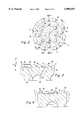
- FIG. 1 shows a partial perspective view illustrating a drill bit and tube of a drilling tube according to the present invention
- FIG. 2 shows a front end view of a head portion according to FIG. 1;
- FIG. 3 shows a section taken along line A--A in FIG. 2;
- FIG. 4 shows a section taken along line B--B in FIG. 2.
- a rock drill bit which in a usual manner comprises a substantially cylindrical head portion 1 and a more slender shaft 2.
- the head portion 1 comprises a front surface or a front side designated with 3, in which a number of inserts are mounted. More precisely the front surface includes a first (or inner) surface portion 4 which is recessed to a certain depth in relation to a surrounding second (or outer) surface portion 5.
- the inserts 7 in this case project somewhat outside the periphery of the head portion in order to machine a hole during drilling which has a somewhat bigger diameter than the very head portion.
- Recesses 8 are provided in areas between adjacent peripheral inserts 7, through which flush medium can pass.
- a number of front inserts are provided also in the area located inside the peripheral inserts 7, which depending on their position, are designated by numerals 9 and 10, respectively.
- the rock drill bit is coupled to a drill tube T in a drill string by means of a threaded connection TH.
- the tube includes a channel for conveying fluid.
- a main channel 11 for flush medium is provided inside the drill bit.
- This main channel communicates at its forward end with a number of branch channels 12, which terminate in the first, recessed surface portion 4.
- branch channels 12 which terminate in the first, recessed surface portion 4.
- one or more flush medium channels also can terminate in said recesses 8.
- the flush medium will in practice comprises water or air.
- the second surface portion 5 constitutes a part of an endless land portion or material portion 13 which in the example is substantially circularly ring-shaped.
- this land portion 13 completely surrounds the recessed space 14 whose bottom is formed by the first surface portion 4.
- the land portion 13 forms a circumferential edging which borders the mainly cylindrical, although shallow space 14, the bottom of which space is formed by the first surface portion 4.
- both surface portions 4, 5 are substantially planar and mutually parallel.
- the surface portions extend essentially perpendicularly to the longitudinal central axis of the drill bit. Since having the land portion 13 is endless, i.e. it lacks disruptions in the form of radial evacuation grooves, the flush medium that is fed out through channels 12 will form a cushion or pool, which is retained by the endless land portion.
- the four front inserts which are designated by numeral 9, are secured in the ring-shaped, planar surface portion 5.
- these front inserts are spaced equi-distantly.
- the remaining four front inserts which are designated by numeral 10 are secured in the recessed surface portion or bottom 4, in an irregular pattern.
- these front inserts 10 project farther from the surface portion 4 than the depth with which this surface 4 is recessed in relation to the surrounding, ring-shaped surface portion 5.
- the front inserts 10 have a height relative to the surface portion 5 which is substantially equal to the height of the front inserts 9 relative to the surface portion 5.
- This means that the inserts 10 project to a common planar level P which is spaced from that of the common planar level P' of the front inserts 9.
- the central front inserts 10 are somewhat longitudinally recessed in relation to the surrounding, more peripheral front inserts 9.
- inserts advantageously are made of cemented carbide.
- the shape of the inserts may vary considerably. They can thus be spherical, conical, ballistic or semi-ballistic.
- each individual space 15 is substantially semicircular.
- An individual branch channel 12 for flush medium terminates at least partially in the planar bottom of each such space 15 which bottom is defined by the surface portion 4. It may also be noted that each individual space 15 is located about midway between two adjacent outer front inserts 9. The cushion of flush medium which is formed in the space 14 will thus continuously be supplied with flush medium via four equidistantly separate channels. That guarantees an even discharge of flush medium to all parts of the space 14.
- the area of the first, recessed surface portion 4 can amount to 30-65%, more preferably 40-55% of the total area of the planar surface which exists inside a circular edge 16 defined by the intersection of surface portion 5 and the conical surface 6.
- the space 14 occupies a relatively large part of the entire front surface.
- the depth of the space 14 relative to the surface portion 5 may vary within fairly wide limits, for example in the area of 1-7 mm for drill bits with ordinary diameters. In the shown example, where the drill bit has an operative outer diameter of about 100 mm, the depth of the pool-like space 14 amounts to about 2.5 mm.
- the height of the inserts 9, 10 can be in the range of 6-12, more preferably 8-10 mm. (Note: the height of each insert 9 is measured from the surface 5, and the height of each insert 10 is measured from the surface 4.)
- the endless, ring-shaped land portion 13 guarantees the formation of a continuous, maintained cushion of flush medium, water for example, in the space 14, the centrally positioned front inserts 10 will be flushed in a versatile and intensive manner with flush medium, ensuring efficient cooling of the inserts in all operational phases of the drill bit, i.e. during each part of an individual impact movement as well as during each part of a return movement. Each impact will further immerse the front inserts with flush medium.
- the endless land portion 13 lacks deep evacuation grooves, the flush medium will flow away from the cushion in an essentially evenly distributed radially directed flow from the recessed space 14 to the ring-shaped space between the bore wall and the surface of the head portion. More exactly, the flush medium will flow evenly across the planar surface portion 5 of the land portion. This means that also inserts 7 and 9 are subjected to an essentially evenly distributed cooling.
- the present invention is not limited to the described embodiment and the associated drawings.
- the front surface of the head portion can include two or more recessed spaces 14.
- the surface portions 4, 5 need not necessarily be planar.
- the surface portion 4 can have a somewhat dome-shaped form in the recessed space 14.
- the surrounding surface portion 5 can have a structure which differs from the smooth planar shape.
- the surface portion 5 can be rough.
- An essential feature of the present invention is that the endless land portion 13 does not have any deep grooves which allow concentrated evacuation of flush medium.
Abstract
Description
Claims (13)
Applications Claiming Priority (2)
| Application Number | Priority Date | Filing Date | Title |
|---|---|---|---|
| SE9600983A SE508490C2 (en) | 1996-03-14 | 1996-03-14 | Rock drill bit for striking drilling |
| SE9600983 | 1996-03-14 |
Publications (1)
| Publication Number | Publication Date |
|---|---|
| US5890551A true US5890551A (en) | 1999-04-06 |
Family
ID=20401790
Family Applications (1)
| Application Number | Title | Priority Date | Filing Date |
|---|---|---|---|
| US08/812,730 Expired - Lifetime US5890551A (en) | 1996-03-14 | 1997-03-06 | Rock drilling tool including a drill bit having a recess in a front surface thereof |
Country Status (10)
| Country | Link |
|---|---|
| US (1) | US5890551A (en) |
| EP (1) | EP0886715B1 (en) |
| JP (1) | JP3920346B2 (en) |
| AT (1) | ATE201479T1 (en) |
| AU (1) | AU709176B2 (en) |
| BR (1) | BR9708044A (en) |
| DE (1) | DE69704931T2 (en) |
| SE (1) | SE508490C2 (en) |
| WO (1) | WO1997034072A1 (en) |
| ZA (1) | ZA972008B (en) |
Cited By (24)
| Publication number | Priority date | Publication date | Assignee | Title |
|---|---|---|---|---|
| US6105693A (en) * | 1999-02-18 | 2000-08-22 | Sandvik Ab | Partially enhanced percussive drill bit |
| US6435288B1 (en) | 2000-09-18 | 2002-08-20 | Cubex Limited | Rock drill bit |
| AU752097B2 (en) * | 1999-02-18 | 2002-09-05 | Sandvik Intellectual Property Ab | Drill bit |
| US6508318B1 (en) * | 1999-11-25 | 2003-01-21 | Sandvik Ab | Percussive rock drill bit and buttons therefor and method for manufacturing drill bit |
| WO2005056972A1 (en) * | 2003-12-09 | 2005-06-23 | Sandvik Intellectual Property Ab | Rock drill bit |
| US6918455B2 (en) * | 1997-06-30 | 2005-07-19 | Smith International | Drill bit with large inserts |
| US20060060389A1 (en) * | 2004-09-21 | 2006-03-23 | Sandvik Intellectual Property Ab | Rock drill bit having outer and inner rock-crushing buttons |
| US20060131075A1 (en) * | 2003-06-12 | 2006-06-22 | Cruz Antonio Maria Guimaraes L | Percussive drill bit |
| US20060162965A1 (en) * | 2004-11-17 | 2006-07-27 | Sandvik Intellectual Property Ab | Rock drill bit |
| US20060249309A1 (en) * | 2003-05-26 | 2006-11-09 | Cruz Antonio Maria Guimaraes L | Drill bit, system, and method for drilling a borehole in an earth formation |
| US20070039761A1 (en) * | 2004-05-25 | 2007-02-22 | Cruz Antonio Mari G L | Percussive drill bit, drilling system comprising such a drill bit and method of drilling a bore hole |
| US20080087473A1 (en) * | 2006-10-13 | 2008-04-17 | Hall David R | Percussive Drill Bit |
| US20130180785A1 (en) * | 2010-09-22 | 2013-07-18 | Sandvik Intellectual Property Ab | Rock drill bit for percussive drilling and a rock drill bit button |
| EP2990589A1 (en) | 2014-08-25 | 2016-03-02 | Sandvik Intellectual Property AB | Drill bit with recessed cutting face |
| CN105927159A (en) * | 2016-06-08 | 2016-09-07 | 莱州市原野科技有限公司 | Polycrystalline diamond compact (PDC) bit |
| US20160320267A1 (en) * | 2014-01-03 | 2016-11-03 | Korea Institute Of Industrial Technology | Apparatus and method for testing drilling efficiency of drill bit |
| USD823908S1 (en) * | 2015-05-29 | 2018-07-24 | Atlas Copco Secoroc Ab | Rock drill bit |
| USD828415S1 (en) * | 2016-07-14 | 2018-09-11 | Mitsubishi Materials Corporation | Drill bit tip |
| USD828416S1 (en) * | 2016-07-14 | 2018-09-11 | Mitsubishi Materials Corporation | Drill bit tip |
| USD832318S1 (en) * | 2016-07-14 | 2018-10-30 | Mitsubishi Materials Corporation | Drill bit tip |
| USD861051S1 (en) * | 2018-03-13 | 2019-09-24 | Robit Oyj | Drill bit |
| USD870168S1 (en) | 2018-03-13 | 2019-12-17 | Robit Oyj | Drill bit |
| USD872142S1 (en) * | 2015-05-21 | 2020-01-07 | Center Rock Inc. | Drill bit for a down-the-hole drill hammer |
| USD1009108S1 (en) * | 2020-09-21 | 2023-12-26 | Kyocera Unimerco Tooling A/S | Drill |
Families Citing this family (8)
| Publication number | Priority date | Publication date | Assignee | Title |
|---|---|---|---|---|
| JP4706639B2 (en) * | 2007-01-18 | 2011-06-22 | 三菱マテリアル株式会社 | Drilling tools |
| US20090271161A1 (en) * | 2008-04-25 | 2009-10-29 | Baker Hughes Incorporated | Arrangement of cutting elements on roller cones for earth boring bits |
| DE102010050244B4 (en) | 2010-10-30 | 2013-10-17 | Technische Universität Bergakademie Freiberg | Chisel direct drive for tools based on a heat engine |
| GB2516626B (en) * | 2013-07-25 | 2018-01-10 | Padley & Venables Ltd | Percussive Drill Bit |
| CN104594811A (en) * | 2013-10-31 | 2015-05-06 | 赵兵 | Rock water drilling machine row-hole drill bit |
| JP2019124009A (en) * | 2018-01-12 | 2019-07-25 | 大智株式会社 | Drilling machine, rotational drilling machine, drilling method and drilling bit |
| JP7111356B2 (en) * | 2018-12-06 | 2022-08-02 | 大智株式会社 | Drilling rigs and rotary excavators |
| JP7177471B2 (en) * | 2018-12-21 | 2022-11-24 | 大智株式会社 | Drilling rigs and rotary excavators |
Citations (12)
| Publication number | Priority date | Publication date | Assignee | Title |
|---|---|---|---|---|
| US3322218A (en) * | 1965-05-04 | 1967-05-30 | Exxon Production Research Co | Multi-port diamond bit |
| US3388756A (en) * | 1965-03-29 | 1968-06-18 | Varel Mfg Company | Percussion bit |
| US3583504A (en) * | 1969-02-24 | 1971-06-08 | Mission Mfg Co | Gauge cutting bit |
| US4323130A (en) * | 1980-06-11 | 1982-04-06 | Strata Bit Corporation | Drill bit |
| US4527642A (en) * | 1982-09-21 | 1985-07-09 | Norton Christensen, Inc. | Earth-boring drill bit with rectangular nozzles |
| SU1227799A1 (en) * | 1984-04-18 | 1986-04-30 | Предприятие П/Я М-5903 | Drilling crown bit |
| US4598779A (en) * | 1983-09-20 | 1986-07-08 | Santrade Limited | Rock drill bit |
| US4730682A (en) * | 1985-12-23 | 1988-03-15 | Ingersoll-Rand Company | Erosion resistant rock drill bit |
| US4776411A (en) * | 1987-03-23 | 1988-10-11 | Smith International, Inc. | Fluid flow control for drag bits |
| US4869330A (en) * | 1988-01-20 | 1989-09-26 | Eastman Christensen Company | Apparatus for establishing hydraulic flow regime in drill bits |
| GB2242464A (en) * | 1990-03-26 | 1991-10-02 | Sandvik Ab | Drill bit |
| US5435402A (en) * | 1994-09-28 | 1995-07-25 | Ziegenfuss; Mark | Self-propelled earth drilling hammer-bit assembly |
Family Cites Families (2)
| Publication number | Priority date | Publication date | Assignee | Title |
|---|---|---|---|---|
| DE1911188A1 (en) * | 1969-03-05 | 1972-02-24 | Richard Karnebogen | Carbide tipped hammer drill bit Password: double tangent cutting |
| DE3519092A1 (en) * | 1985-05-28 | 1986-01-02 | Frank Dr. 7000 Stuttgart Kasper | Tandem vane motor |
-
1996
- 1996-03-14 SE SE9600983A patent/SE508490C2/en not_active IP Right Cessation
-
1997
- 1997-02-20 BR BR9708044A patent/BR9708044A/en not_active IP Right Cessation
- 1997-02-20 AU AU20482/97A patent/AU709176B2/en not_active Expired
- 1997-02-20 JP JP53250297A patent/JP3920346B2/en not_active Expired - Fee Related
- 1997-02-20 DE DE69704931T patent/DE69704931T2/en not_active Expired - Lifetime
- 1997-02-20 EP EP97908613A patent/EP0886715B1/en not_active Expired - Lifetime
- 1997-02-20 AT AT97908613T patent/ATE201479T1/en active
- 1997-02-20 WO PCT/SE1997/000285 patent/WO1997034072A1/en active IP Right Grant
- 1997-03-06 US US08/812,730 patent/US5890551A/en not_active Expired - Lifetime
- 1997-03-07 ZA ZA9702008A patent/ZA972008B/en unknown
Patent Citations (12)
| Publication number | Priority date | Publication date | Assignee | Title |
|---|---|---|---|---|
| US3388756A (en) * | 1965-03-29 | 1968-06-18 | Varel Mfg Company | Percussion bit |
| US3322218A (en) * | 1965-05-04 | 1967-05-30 | Exxon Production Research Co | Multi-port diamond bit |
| US3583504A (en) * | 1969-02-24 | 1971-06-08 | Mission Mfg Co | Gauge cutting bit |
| US4323130A (en) * | 1980-06-11 | 1982-04-06 | Strata Bit Corporation | Drill bit |
| US4527642A (en) * | 1982-09-21 | 1985-07-09 | Norton Christensen, Inc. | Earth-boring drill bit with rectangular nozzles |
| US4598779A (en) * | 1983-09-20 | 1986-07-08 | Santrade Limited | Rock drill bit |
| SU1227799A1 (en) * | 1984-04-18 | 1986-04-30 | Предприятие П/Я М-5903 | Drilling crown bit |
| US4730682A (en) * | 1985-12-23 | 1988-03-15 | Ingersoll-Rand Company | Erosion resistant rock drill bit |
| US4776411A (en) * | 1987-03-23 | 1988-10-11 | Smith International, Inc. | Fluid flow control for drag bits |
| US4869330A (en) * | 1988-01-20 | 1989-09-26 | Eastman Christensen Company | Apparatus for establishing hydraulic flow regime in drill bits |
| GB2242464A (en) * | 1990-03-26 | 1991-10-02 | Sandvik Ab | Drill bit |
| US5435402A (en) * | 1994-09-28 | 1995-07-25 | Ziegenfuss; Mark | Self-propelled earth drilling hammer-bit assembly |
Non-Patent Citations (2)
| Title |
|---|
| "RAMBLAST Percussion Bits"; a brochure from Hughes Tool Division. Jul. 1991. |
| RAMBLAST Percussion Bits ; a brochure from Hughes Tool Division. Jul. 1991. * |
Cited By (44)
| Publication number | Priority date | Publication date | Assignee | Title |
|---|---|---|---|---|
| US6918455B2 (en) * | 1997-06-30 | 2005-07-19 | Smith International | Drill bit with large inserts |
| US6105693A (en) * | 1999-02-18 | 2000-08-22 | Sandvik Ab | Partially enhanced percussive drill bit |
| AU752097B2 (en) * | 1999-02-18 | 2002-09-05 | Sandvik Intellectual Property Ab | Drill bit |
| US6508318B1 (en) * | 1999-11-25 | 2003-01-21 | Sandvik Ab | Percussive rock drill bit and buttons therefor and method for manufacturing drill bit |
| US6658968B2 (en) | 1999-11-25 | 2003-12-09 | Sandvik Ab | Percussive rock drill bit and buttons therefor and method for manufacturing drill bit |
| AU775817B2 (en) * | 1999-11-25 | 2004-08-19 | Sandvik Intellectual Property Ab | A method for the manufacturing of a drill bit for percussive rock drilling and a rock drill bit and buttons therefor |
| US6435288B1 (en) | 2000-09-18 | 2002-08-20 | Cubex Limited | Rock drill bit |
| US7726419B2 (en) | 2003-05-26 | 2010-06-01 | Shell Oil Company | Drill bit, system, and method for drilling a borehole in an earth formation |
| US20060249309A1 (en) * | 2003-05-26 | 2006-11-09 | Cruz Antonio Maria Guimaraes L | Drill bit, system, and method for drilling a borehole in an earth formation |
| US20060131075A1 (en) * | 2003-06-12 | 2006-06-22 | Cruz Antonio Maria Guimaraes L | Percussive drill bit |
| US7546888B2 (en) * | 2003-06-12 | 2009-06-16 | Shell Oil Company | Percussive drill bit |
| US20070137900A1 (en) * | 2003-12-09 | 2007-06-21 | Fredrik Bjork | Rock drill bit |
| WO2005056972A1 (en) * | 2003-12-09 | 2005-06-23 | Sandvik Intellectual Property Ab | Rock drill bit |
| AU2004297490B2 (en) * | 2003-12-09 | 2009-06-18 | Sandvik Intellectual Property Ab | Rock drill bit |
| US7392863B2 (en) | 2003-12-09 | 2008-07-01 | Sandvik Intellectual Property Ab | Rock drill bit |
| US20070039761A1 (en) * | 2004-05-25 | 2007-02-22 | Cruz Antonio Mari G L | Percussive drill bit, drilling system comprising such a drill bit and method of drilling a bore hole |
| US7455126B2 (en) | 2004-05-25 | 2008-11-25 | Shell Oil Company | Percussive drill bit, drilling system comprising such a drill bit and method of drilling a bore hole |
| EP1794406A4 (en) * | 2004-09-21 | 2014-10-29 | Sandvik Intellectual Property | Rock drill bit |
| US7296641B2 (en) | 2004-09-21 | 2007-11-20 | Sandvik Intellectual Property Ab | Rock drill bit having outer and inner rock-crushing buttons |
| CN101023240B (en) * | 2004-09-21 | 2013-03-27 | 山特维克知识产权股份有限公司 | Rock drill bit |
| EP1794406A1 (en) * | 2004-09-21 | 2007-06-13 | Sandvik Intellectual Property AB | Rock drill bit |
| US20060060389A1 (en) * | 2004-09-21 | 2006-03-23 | Sandvik Intellectual Property Ab | Rock drill bit having outer and inner rock-crushing buttons |
| WO2006033606A1 (en) * | 2004-09-21 | 2006-03-30 | Sandvik Intellectual Property Ab | Rock drill bit |
| US20060162965A1 (en) * | 2004-11-17 | 2006-07-27 | Sandvik Intellectual Property Ab | Rock drill bit |
| US7281594B2 (en) | 2004-11-17 | 2007-10-16 | Sandvik Intellectual Property Ab | Rock drill bit |
| US20080087473A1 (en) * | 2006-10-13 | 2008-04-17 | Hall David R | Percussive Drill Bit |
| US7527110B2 (en) * | 2006-10-13 | 2009-05-05 | Hall David R | Percussive drill bit |
| US20130180785A1 (en) * | 2010-09-22 | 2013-07-18 | Sandvik Intellectual Property Ab | Rock drill bit for percussive drilling and a rock drill bit button |
| US20160320267A1 (en) * | 2014-01-03 | 2016-11-03 | Korea Institute Of Industrial Technology | Apparatus and method for testing drilling efficiency of drill bit |
| US10041861B2 (en) * | 2014-01-03 | 2018-08-07 | Korea Institute Of Industrial Technology | Apparatus and method for testing drilling efficiency of drill bit |
| WO2016030036A1 (en) | 2014-08-25 | 2016-03-03 | Sandvik Intellectual Property Ab | Drill bit with recessed cutting face |
| US10501997B2 (en) | 2014-08-25 | 2019-12-10 | Sandvik Intellectual Property Ab | Drill bit with recessed cutting face |
| EP2990589A1 (en) | 2014-08-25 | 2016-03-02 | Sandvik Intellectual Property AB | Drill bit with recessed cutting face |
| USD872142S1 (en) * | 2015-05-21 | 2020-01-07 | Center Rock Inc. | Drill bit for a down-the-hole drill hammer |
| USD823908S1 (en) * | 2015-05-29 | 2018-07-24 | Atlas Copco Secoroc Ab | Rock drill bit |
| USD831714S1 (en) | 2015-05-29 | 2018-10-23 | Atlas Copco Secoroc Ab | Rock drill bit |
| CN105927159B (en) * | 2016-06-08 | 2017-11-07 | 莱州市原野科技有限公司 | Pdc drill bit |
| CN105927159A (en) * | 2016-06-08 | 2016-09-07 | 莱州市原野科技有限公司 | Polycrystalline diamond compact (PDC) bit |
| USD828415S1 (en) * | 2016-07-14 | 2018-09-11 | Mitsubishi Materials Corporation | Drill bit tip |
| USD828416S1 (en) * | 2016-07-14 | 2018-09-11 | Mitsubishi Materials Corporation | Drill bit tip |
| USD832318S1 (en) * | 2016-07-14 | 2018-10-30 | Mitsubishi Materials Corporation | Drill bit tip |
| USD861051S1 (en) * | 2018-03-13 | 2019-09-24 | Robit Oyj | Drill bit |
| USD870168S1 (en) | 2018-03-13 | 2019-12-17 | Robit Oyj | Drill bit |
| USD1009108S1 (en) * | 2020-09-21 | 2023-12-26 | Kyocera Unimerco Tooling A/S | Drill |
Also Published As
| Publication number | Publication date |
|---|---|
| DE69704931D1 (en) | 2001-06-28 |
| ZA972008B (en) | 1997-09-09 |
| AU2048297A (en) | 1997-10-01 |
| EP0886715A1 (en) | 1998-12-30 |
| JP2000506574A (en) | 2000-05-30 |
| SE508490C2 (en) | 1998-10-12 |
| DE69704931T2 (en) | 2001-10-04 |
| SE9600983L (en) | 1997-09-15 |
| BR9708044A (en) | 1999-07-27 |
| EP0886715B1 (en) | 2001-05-23 |
| WO1997034072A1 (en) | 1997-09-18 |
| SE9600983D0 (en) | 1996-03-14 |
| AU709176B2 (en) | 1999-08-26 |
| ATE201479T1 (en) | 2001-06-15 |
| JP3920346B2 (en) | 2007-05-30 |
Similar Documents
| Publication | Publication Date | Title |
|---|---|---|
| US5890551A (en) | Rock drilling tool including a drill bit having a recess in a front surface thereof | |
| EP0418706B1 (en) | Earth boring bit for soft to hard formations | |
| US5531281A (en) | Rotary drilling tools | |
| US5016718A (en) | Combination drill bit | |
| US4538691A (en) | Rotary drill bit | |
| US5103922A (en) | Fishtail expendable diamond drag bit | |
| KR101240763B1 (en) | Rock drill bit | |
| US4640374A (en) | Rotary drill bit | |
| US5244039A (en) | Rotary drill bits | |
| US4168755A (en) | Nutating drill bit | |
| KR20070053285A (en) | Rock drill bit | |
| RU2658184C2 (en) | Percussive rock drill bit with optimised gauge buttons | |
| US3768581A (en) | Frustro-conical drilling bit having radially tiered groups of teeth | |
| EP0742342A2 (en) | Rotary drill bit | |
| US4730682A (en) | Erosion resistant rock drill bit | |
| CN107075913A (en) | The drill bit in the cutting face with depression | |
| US4069880A (en) | Excavation tool | |
| US4363367A (en) | Large diameter drill bit | |
| CA2248688C (en) | Rock drill bit and a rock drilling tool | |
| US4231438A (en) | Straight hole insert drill bit | |
| GB2190120A (en) | Improvements in or relating to rotary drill bits | |
| KR20160133445A (en) | Percussive drill bit with multiple sets of front cutting inserts | |
| KR20030064759A (en) | Cutting insert for percussion drill bit | |
| SU1086112A1 (en) | Drill crown | |
| KR20230054362A (en) | Carved out drill bit |
Legal Events
| Date | Code | Title | Description |
|---|---|---|---|
| AS | Assignment |
Owner name: SANDVIK AB, SWEDEN Free format text: ASSIGNMENT OF ASSIGNORS INTEREST;ASSIGNORS:LILJEBRAND, PER-OLOF;OLSSON, ORBAN;REEL/FRAME:008689/0072 Effective date: 19970417 |
|
| STCF | Information on status: patent grant |
Free format text: PATENTED CASE |
|
| FPAY | Fee payment |
Year of fee payment: 4 |
|
| AS | Assignment |
Owner name: SANDVIK INTELLECTUAL PROPERTY HB, SWEDEN Free format text: ASSIGNMENT OF ASSIGNORS INTEREST;ASSIGNOR:SANDVIK AB;REEL/FRAME:016290/0628 Effective date: 20050516 Owner name: SANDVIK INTELLECTUAL PROPERTY HB,SWEDEN Free format text: ASSIGNMENT OF ASSIGNORS INTEREST;ASSIGNOR:SANDVIK AB;REEL/FRAME:016290/0628 Effective date: 20050516 |
|
| AS | Assignment |
Owner name: SANDVIK INTELLECTUAL PROPERTY AKTIEBOLAG, SWEDEN Free format text: ASSIGNMENT OF ASSIGNORS INTEREST;ASSIGNOR:SANDVIK INTELLECTUAL PROPERTY HB;REEL/FRAME:016621/0366 Effective date: 20050630 Owner name: SANDVIK INTELLECTUAL PROPERTY AKTIEBOLAG,SWEDEN Free format text: ASSIGNMENT OF ASSIGNORS INTEREST;ASSIGNOR:SANDVIK INTELLECTUAL PROPERTY HB;REEL/FRAME:016621/0366 Effective date: 20050630 |
|
| FPAY | Fee payment |
Year of fee payment: 8 |
|
| FPAY | Fee payment |
Year of fee payment: 12 |