US5889263A - Apparatus and a method for induction sealing - Google Patents
Apparatus and a method for induction sealing Download PDFInfo
- Publication number
- US5889263A US5889263A US08/820,939 US82093997A US5889263A US 5889263 A US5889263 A US 5889263A US 82093997 A US82093997 A US 82093997A US 5889263 A US5889263 A US 5889263A
- Authority
- US
- United States
- Prior art keywords
- packaging material
- conductors
- inductor
- transverse
- sealing
- Prior art date
- Legal status (The legal status is an assumption and is not a legal conclusion. Google has not performed a legal analysis and makes no representation as to the accuracy of the status listed.)
- Expired - Lifetime
Links
- 238000007789 sealing Methods 0.000 title claims abstract description 40
- 238000000034 method Methods 0.000 title claims abstract description 8
- 230000006698 induction Effects 0.000 title abstract description 4
- 239000004020 conductor Substances 0.000 claims abstract description 50
- 239000005022 packaging material Substances 0.000 claims abstract description 48
- 239000011888 foil Substances 0.000 claims abstract description 11
- 229920001169 thermoplastic Polymers 0.000 claims description 20
- 239000004416 thermosoftening plastic Substances 0.000 claims description 20
- 239000002184 metal Substances 0.000 claims description 13
- 229910052751 metal Inorganic materials 0.000 claims description 13
- 230000015572 biosynthetic process Effects 0.000 claims description 4
- 230000004927 fusion Effects 0.000 claims description 3
- 230000001939 inductive effect Effects 0.000 claims description 2
- 239000012815 thermoplastic material Substances 0.000 claims 1
- 229910052782 aluminium Inorganic materials 0.000 abstract description 4
- XAGFODPZIPBFFR-UHFFFAOYSA-N aluminium Chemical compound [Al] XAGFODPZIPBFFR-UHFFFAOYSA-N 0.000 abstract description 4
- 239000010410 layer Substances 0.000 description 34
- 239000000463 material Substances 0.000 description 31
- 239000000047 product Substances 0.000 description 14
- 238000004806 packaging method and process Methods 0.000 description 8
- 239000005030 aluminium foil Substances 0.000 description 6
- 238000010586 diagram Methods 0.000 description 5
- 239000004033 plastic Substances 0.000 description 4
- 229920003023 plastic Polymers 0.000 description 4
- 239000004411 aluminium Substances 0.000 description 3
- 238000010438 heat treatment Methods 0.000 description 3
- 239000007788 liquid Substances 0.000 description 3
- 235000015113 tomato pastes and purées Nutrition 0.000 description 3
- 230000004888 barrier function Effects 0.000 description 2
- 238000000576 coating method Methods 0.000 description 2
- 239000012792 core layer Substances 0.000 description 2
- 235000013305 food Nutrition 0.000 description 2
- -1 for example Polymers 0.000 description 2
- 239000012263 liquid product Substances 0.000 description 2
- 238000004519 manufacturing process Methods 0.000 description 2
- 238000013021 overheating Methods 0.000 description 2
- 239000000123 paper Substances 0.000 description 2
- 239000011087 paperboard Substances 0.000 description 2
- 239000007921 spray Substances 0.000 description 2
- XLYOFNOQVPJJNP-UHFFFAOYSA-N water Substances O XLYOFNOQVPJJNP-UHFFFAOYSA-N 0.000 description 2
- 239000004698 Polyethylene Substances 0.000 description 1
- 230000006978 adaptation Effects 0.000 description 1
- 238000013459 approach Methods 0.000 description 1
- 239000011324 bead Substances 0.000 description 1
- 239000011248 coating agent Substances 0.000 description 1
- 230000006835 compression Effects 0.000 description 1
- 238000007906 compression Methods 0.000 description 1
- 239000012141 concentrate Substances 0.000 description 1
- 238000013461 design Methods 0.000 description 1
- 235000011389 fruit/vegetable juice Nutrition 0.000 description 1
- 230000020169 heat generation Effects 0.000 description 1
- 238000009413 insulation Methods 0.000 description 1
- 235000013336 milk Nutrition 0.000 description 1
- 239000008267 milk Substances 0.000 description 1
- 210000004080 milk Anatomy 0.000 description 1
- 238000012856 packing Methods 0.000 description 1
- 229920000573 polyethylene Polymers 0.000 description 1
- 230000001105 regulatory effect Effects 0.000 description 1
Images


Classifications
-
- B—PERFORMING OPERATIONS; TRANSPORTING
- B29—WORKING OF PLASTICS; WORKING OF SUBSTANCES IN A PLASTIC STATE IN GENERAL
- B29C—SHAPING OR JOINING OF PLASTICS; SHAPING OF MATERIAL IN A PLASTIC STATE, NOT OTHERWISE PROVIDED FOR; AFTER-TREATMENT OF THE SHAPED PRODUCTS, e.g. REPAIRING
- B29C65/00—Joining or sealing of preformed parts, e.g. welding of plastics materials; Apparatus therefor
- B29C65/02—Joining or sealing of preformed parts, e.g. welding of plastics materials; Apparatus therefor by heating, with or without pressure
- B29C65/34—Joining or sealing of preformed parts, e.g. welding of plastics materials; Apparatus therefor by heating, with or without pressure using heated elements which remain in the joint, e.g. "verlorenes Schweisselement"
- B29C65/36—Joining or sealing of preformed parts, e.g. welding of plastics materials; Apparatus therefor by heating, with or without pressure using heated elements which remain in the joint, e.g. "verlorenes Schweisselement" heated by induction
- B29C65/3672—Joining or sealing of preformed parts, e.g. welding of plastics materials; Apparatus therefor by heating, with or without pressure using heated elements which remain in the joint, e.g. "verlorenes Schweisselement" heated by induction characterised by the composition of the elements heated by induction which remain in the joint
- B29C65/3676—Joining or sealing of preformed parts, e.g. welding of plastics materials; Apparatus therefor by heating, with or without pressure using heated elements which remain in the joint, e.g. "verlorenes Schweisselement" heated by induction characterised by the composition of the elements heated by induction which remain in the joint being metallic
- B29C65/368—Joining or sealing of preformed parts, e.g. welding of plastics materials; Apparatus therefor by heating, with or without pressure using heated elements which remain in the joint, e.g. "verlorenes Schweisselement" heated by induction characterised by the composition of the elements heated by induction which remain in the joint being metallic with a polymer coating
-
- B—PERFORMING OPERATIONS; TRANSPORTING
- B29—WORKING OF PLASTICS; WORKING OF SUBSTANCES IN A PLASTIC STATE IN GENERAL
- B29C—SHAPING OR JOINING OF PLASTICS; SHAPING OF MATERIAL IN A PLASTIC STATE, NOT OTHERWISE PROVIDED FOR; AFTER-TREATMENT OF THE SHAPED PRODUCTS, e.g. REPAIRING
- B29C65/00—Joining or sealing of preformed parts, e.g. welding of plastics materials; Apparatus therefor
- B29C65/02—Joining or sealing of preformed parts, e.g. welding of plastics materials; Apparatus therefor by heating, with or without pressure
- B29C65/34—Joining or sealing of preformed parts, e.g. welding of plastics materials; Apparatus therefor by heating, with or without pressure using heated elements which remain in the joint, e.g. "verlorenes Schweisselement"
- B29C65/36—Joining or sealing of preformed parts, e.g. welding of plastics materials; Apparatus therefor by heating, with or without pressure using heated elements which remain in the joint, e.g. "verlorenes Schweisselement" heated by induction
- B29C65/3604—Joining or sealing of preformed parts, e.g. welding of plastics materials; Apparatus therefor by heating, with or without pressure using heated elements which remain in the joint, e.g. "verlorenes Schweisselement" heated by induction characterised by the type of elements heated by induction which remain in the joint
- B29C65/3656—Joining or sealing of preformed parts, e.g. welding of plastics materials; Apparatus therefor by heating, with or without pressure using heated elements which remain in the joint, e.g. "verlorenes Schweisselement" heated by induction characterised by the type of elements heated by induction which remain in the joint being a layer of a multilayer part to be joined, e.g. for joining plastic-metal laminates
-
- B—PERFORMING OPERATIONS; TRANSPORTING
- B29—WORKING OF PLASTICS; WORKING OF SUBSTANCES IN A PLASTIC STATE IN GENERAL
- B29C—SHAPING OR JOINING OF PLASTICS; SHAPING OF MATERIAL IN A PLASTIC STATE, NOT OTHERWISE PROVIDED FOR; AFTER-TREATMENT OF THE SHAPED PRODUCTS, e.g. REPAIRING
- B29C65/00—Joining or sealing of preformed parts, e.g. welding of plastics materials; Apparatus therefor
- B29C65/02—Joining or sealing of preformed parts, e.g. welding of plastics materials; Apparatus therefor by heating, with or without pressure
- B29C65/34—Joining or sealing of preformed parts, e.g. welding of plastics materials; Apparatus therefor by heating, with or without pressure using heated elements which remain in the joint, e.g. "verlorenes Schweisselement"
- B29C65/36—Joining or sealing of preformed parts, e.g. welding of plastics materials; Apparatus therefor by heating, with or without pressure using heated elements which remain in the joint, e.g. "verlorenes Schweisselement" heated by induction
- B29C65/3668—Joining or sealing of preformed parts, e.g. welding of plastics materials; Apparatus therefor by heating, with or without pressure using heated elements which remain in the joint, e.g. "verlorenes Schweisselement" heated by induction characterised by the means for supplying heat to said heated elements which remain in the join, e.g. special induction coils
-
- B—PERFORMING OPERATIONS; TRANSPORTING
- B29—WORKING OF PLASTICS; WORKING OF SUBSTANCES IN A PLASTIC STATE IN GENERAL
- B29C—SHAPING OR JOINING OF PLASTICS; SHAPING OF MATERIAL IN A PLASTIC STATE, NOT OTHERWISE PROVIDED FOR; AFTER-TREATMENT OF THE SHAPED PRODUCTS, e.g. REPAIRING
- B29C66/00—General aspects of processes or apparatus for joining preformed parts
- B29C66/01—General aspects dealing with the joint area or with the area to be joined
- B29C66/05—Particular design of joint configurations
- B29C66/10—Particular design of joint configurations particular design of the joint cross-sections
- B29C66/11—Joint cross-sections comprising a single joint-segment, i.e. one of the parts to be joined comprising a single joint-segment in the joint cross-section
- B29C66/112—Single lapped joints
- B29C66/1122—Single lap to lap joints, i.e. overlap joints
-
- B—PERFORMING OPERATIONS; TRANSPORTING
- B29—WORKING OF PLASTICS; WORKING OF SUBSTANCES IN A PLASTIC STATE IN GENERAL
- B29C—SHAPING OR JOINING OF PLASTICS; SHAPING OF MATERIAL IN A PLASTIC STATE, NOT OTHERWISE PROVIDED FOR; AFTER-TREATMENT OF THE SHAPED PRODUCTS, e.g. REPAIRING
- B29C66/00—General aspects of processes or apparatus for joining preformed parts
- B29C66/40—General aspects of joining substantially flat articles, e.g. plates, sheets or web-like materials; Making flat seams in tubular or hollow articles; Joining single elements to substantially flat surfaces
- B29C66/41—Joining substantially flat articles ; Making flat seams in tubular or hollow articles
- B29C66/43—Joining a relatively small portion of the surface of said articles
- B29C66/431—Joining the articles to themselves
- B29C66/4312—Joining the articles to themselves for making flat seams in tubular or hollow articles, e.g. transversal seams
-
- B—PERFORMING OPERATIONS; TRANSPORTING
- B29—WORKING OF PLASTICS; WORKING OF SUBSTANCES IN A PLASTIC STATE IN GENERAL
- B29C—SHAPING OR JOINING OF PLASTICS; SHAPING OF MATERIAL IN A PLASTIC STATE, NOT OTHERWISE PROVIDED FOR; AFTER-TREATMENT OF THE SHAPED PRODUCTS, e.g. REPAIRING
- B29C66/00—General aspects of processes or apparatus for joining preformed parts
- B29C66/70—General aspects of processes or apparatus for joining preformed parts characterised by the composition, physical properties or the structure of the material of the parts to be joined; Joining with non-plastics material
- B29C66/72—General aspects of processes or apparatus for joining preformed parts characterised by the composition, physical properties or the structure of the material of the parts to be joined; Joining with non-plastics material characterised by the structure of the material of the parts to be joined
- B29C66/723—General aspects of processes or apparatus for joining preformed parts characterised by the composition, physical properties or the structure of the material of the parts to be joined; Joining with non-plastics material characterised by the structure of the material of the parts to be joined being multi-layered
- B29C66/7232—General aspects of processes or apparatus for joining preformed parts characterised by the composition, physical properties or the structure of the material of the parts to be joined; Joining with non-plastics material characterised by the structure of the material of the parts to be joined being multi-layered comprising a non-plastics layer
- B29C66/72321—General aspects of processes or apparatus for joining preformed parts characterised by the composition, physical properties or the structure of the material of the parts to be joined; Joining with non-plastics material characterised by the structure of the material of the parts to be joined being multi-layered comprising a non-plastics layer consisting of metals or their alloys
-
- B—PERFORMING OPERATIONS; TRANSPORTING
- B29—WORKING OF PLASTICS; WORKING OF SUBSTANCES IN A PLASTIC STATE IN GENERAL
- B29C—SHAPING OR JOINING OF PLASTICS; SHAPING OF MATERIAL IN A PLASTIC STATE, NOT OTHERWISE PROVIDED FOR; AFTER-TREATMENT OF THE SHAPED PRODUCTS, e.g. REPAIRING
- B29C66/00—General aspects of processes or apparatus for joining preformed parts
- B29C66/70—General aspects of processes or apparatus for joining preformed parts characterised by the composition, physical properties or the structure of the material of the parts to be joined; Joining with non-plastics material
- B29C66/72—General aspects of processes or apparatus for joining preformed parts characterised by the composition, physical properties or the structure of the material of the parts to be joined; Joining with non-plastics material characterised by the structure of the material of the parts to be joined
- B29C66/723—General aspects of processes or apparatus for joining preformed parts characterised by the composition, physical properties or the structure of the material of the parts to be joined; Joining with non-plastics material characterised by the structure of the material of the parts to be joined being multi-layered
- B29C66/7232—General aspects of processes or apparatus for joining preformed parts characterised by the composition, physical properties or the structure of the material of the parts to be joined; Joining with non-plastics material characterised by the structure of the material of the parts to be joined being multi-layered comprising a non-plastics layer
- B29C66/72327—General aspects of processes or apparatus for joining preformed parts characterised by the composition, physical properties or the structure of the material of the parts to be joined; Joining with non-plastics material characterised by the structure of the material of the parts to be joined being multi-layered comprising a non-plastics layer consisting of natural products or their composites, not provided for in B29C66/72321 - B29C66/72324
- B29C66/72328—Paper
-
- B—PERFORMING OPERATIONS; TRANSPORTING
- B29—WORKING OF PLASTICS; WORKING OF SUBSTANCES IN A PLASTIC STATE IN GENERAL
- B29C—SHAPING OR JOINING OF PLASTICS; SHAPING OF MATERIAL IN A PLASTIC STATE, NOT OTHERWISE PROVIDED FOR; AFTER-TREATMENT OF THE SHAPED PRODUCTS, e.g. REPAIRING
- B29C66/00—General aspects of processes or apparatus for joining preformed parts
- B29C66/70—General aspects of processes or apparatus for joining preformed parts characterised by the composition, physical properties or the structure of the material of the parts to be joined; Joining with non-plastics material
- B29C66/73—General aspects of processes or apparatus for joining preformed parts characterised by the composition, physical properties or the structure of the material of the parts to be joined; Joining with non-plastics material characterised by the intensive physical properties of the material of the parts to be joined, by the optical properties of the material of the parts to be joined, by the extensive physical properties of the parts to be joined, by the state of the material of the parts to be joined or by the material of the parts to be joined being a thermoplastic or a thermoset
- B29C66/739—General aspects of processes or apparatus for joining preformed parts characterised by the composition, physical properties or the structure of the material of the parts to be joined; Joining with non-plastics material characterised by the intensive physical properties of the material of the parts to be joined, by the optical properties of the material of the parts to be joined, by the extensive physical properties of the parts to be joined, by the state of the material of the parts to be joined or by the material of the parts to be joined being a thermoplastic or a thermoset characterised by the material of the parts to be joined being a thermoplastic or a thermoset
- B29C66/7392—General aspects of processes or apparatus for joining preformed parts characterised by the composition, physical properties or the structure of the material of the parts to be joined; Joining with non-plastics material characterised by the intensive physical properties of the material of the parts to be joined, by the optical properties of the material of the parts to be joined, by the extensive physical properties of the parts to be joined, by the state of the material of the parts to be joined or by the material of the parts to be joined being a thermoplastic or a thermoset characterised by the material of the parts to be joined being a thermoplastic or a thermoset characterised by the material of at least one of the parts being a thermoplastic
- B29C66/73921—General aspects of processes or apparatus for joining preformed parts characterised by the composition, physical properties or the structure of the material of the parts to be joined; Joining with non-plastics material characterised by the intensive physical properties of the material of the parts to be joined, by the optical properties of the material of the parts to be joined, by the extensive physical properties of the parts to be joined, by the state of the material of the parts to be joined or by the material of the parts to be joined being a thermoplastic or a thermoset characterised by the material of the parts to be joined being a thermoplastic or a thermoset characterised by the material of at least one of the parts being a thermoplastic characterised by the materials of both parts being thermoplastics
-
- B—PERFORMING OPERATIONS; TRANSPORTING
- B29—WORKING OF PLASTICS; WORKING OF SUBSTANCES IN A PLASTIC STATE IN GENERAL
- B29C—SHAPING OR JOINING OF PLASTICS; SHAPING OF MATERIAL IN A PLASTIC STATE, NOT OTHERWISE PROVIDED FOR; AFTER-TREATMENT OF THE SHAPED PRODUCTS, e.g. REPAIRING
- B29C66/00—General aspects of processes or apparatus for joining preformed parts
- B29C66/80—General aspects of machine operations or constructions and parts thereof
- B29C66/81—General aspects of the pressing elements, i.e. the elements applying pressure on the parts to be joined in the area to be joined, e.g. the welding jaws or clamps
- B29C66/814—General aspects of the pressing elements, i.e. the elements applying pressure on the parts to be joined in the area to be joined, e.g. the welding jaws or clamps characterised by the design of the pressing elements, e.g. of the welding jaws or clamps
- B29C66/8141—General aspects of the pressing elements, i.e. the elements applying pressure on the parts to be joined in the area to be joined, e.g. the welding jaws or clamps characterised by the design of the pressing elements, e.g. of the welding jaws or clamps characterised by the surface geometry of the part of the pressing elements, e.g. welding jaws or clamps, coming into contact with the parts to be joined
- B29C66/81427—General aspects of the pressing elements, i.e. the elements applying pressure on the parts to be joined in the area to be joined, e.g. the welding jaws or clamps characterised by the design of the pressing elements, e.g. of the welding jaws or clamps characterised by the surface geometry of the part of the pressing elements, e.g. welding jaws or clamps, coming into contact with the parts to be joined comprising a single ridge, e.g. for making a weakening line; comprising a single tooth
-
- B—PERFORMING OPERATIONS; TRANSPORTING
- B29—WORKING OF PLASTICS; WORKING OF SUBSTANCES IN A PLASTIC STATE IN GENERAL
- B29C—SHAPING OR JOINING OF PLASTICS; SHAPING OF MATERIAL IN A PLASTIC STATE, NOT OTHERWISE PROVIDED FOR; AFTER-TREATMENT OF THE SHAPED PRODUCTS, e.g. REPAIRING
- B29C66/00—General aspects of processes or apparatus for joining preformed parts
- B29C66/80—General aspects of machine operations or constructions and parts thereof
- B29C66/81—General aspects of the pressing elements, i.e. the elements applying pressure on the parts to be joined in the area to be joined, e.g. the welding jaws or clamps
- B29C66/814—General aspects of the pressing elements, i.e. the elements applying pressure on the parts to be joined in the area to be joined, e.g. the welding jaws or clamps characterised by the design of the pressing elements, e.g. of the welding jaws or clamps
- B29C66/8141—General aspects of the pressing elements, i.e. the elements applying pressure on the parts to be joined in the area to be joined, e.g. the welding jaws or clamps characterised by the design of the pressing elements, e.g. of the welding jaws or clamps characterised by the surface geometry of the part of the pressing elements, e.g. welding jaws or clamps, coming into contact with the parts to be joined
- B29C66/81431—General aspects of the pressing elements, i.e. the elements applying pressure on the parts to be joined in the area to be joined, e.g. the welding jaws or clamps characterised by the design of the pressing elements, e.g. of the welding jaws or clamps characterised by the surface geometry of the part of the pressing elements, e.g. welding jaws or clamps, coming into contact with the parts to be joined comprising a single cavity, e.g. a groove
-
- B—PERFORMING OPERATIONS; TRANSPORTING
- B29—WORKING OF PLASTICS; WORKING OF SUBSTANCES IN A PLASTIC STATE IN GENERAL
- B29C—SHAPING OR JOINING OF PLASTICS; SHAPING OF MATERIAL IN A PLASTIC STATE, NOT OTHERWISE PROVIDED FOR; AFTER-TREATMENT OF THE SHAPED PRODUCTS, e.g. REPAIRING
- B29C66/00—General aspects of processes or apparatus for joining preformed parts
- B29C66/80—General aspects of machine operations or constructions and parts thereof
- B29C66/81—General aspects of the pressing elements, i.e. the elements applying pressure on the parts to be joined in the area to be joined, e.g. the welding jaws or clamps
- B29C66/818—General aspects of the pressing elements, i.e. the elements applying pressure on the parts to be joined in the area to be joined, e.g. the welding jaws or clamps characterised by the cooling constructional aspects, or by the thermal or electrical insulating or conducting constructional aspects of the welding jaws or of the clamps ; comprising means for compensating for the thermal expansion of the welding jaws or of the clamps
- B29C66/8187—General aspects of the pressing elements, i.e. the elements applying pressure on the parts to be joined in the area to be joined, e.g. the welding jaws or clamps characterised by the cooling constructional aspects, or by the thermal or electrical insulating or conducting constructional aspects of the welding jaws or of the clamps ; comprising means for compensating for the thermal expansion of the welding jaws or of the clamps characterised by the electrical insulating constructional aspects
- B29C66/81871—General aspects of the pressing elements, i.e. the elements applying pressure on the parts to be joined in the area to be joined, e.g. the welding jaws or clamps characterised by the cooling constructional aspects, or by the thermal or electrical insulating or conducting constructional aspects of the welding jaws or of the clamps ; comprising means for compensating for the thermal expansion of the welding jaws or of the clamps characterised by the electrical insulating constructional aspects of the welding jaws
-
- B—PERFORMING OPERATIONS; TRANSPORTING
- B29—WORKING OF PLASTICS; WORKING OF SUBSTANCES IN A PLASTIC STATE IN GENERAL
- B29C—SHAPING OR JOINING OF PLASTICS; SHAPING OF MATERIAL IN A PLASTIC STATE, NOT OTHERWISE PROVIDED FOR; AFTER-TREATMENT OF THE SHAPED PRODUCTS, e.g. REPAIRING
- B29C66/00—General aspects of processes or apparatus for joining preformed parts
- B29C66/80—General aspects of machine operations or constructions and parts thereof
- B29C66/84—Specific machine types or machines suitable for specific applications
- B29C66/849—Packaging machines
-
- B—PERFORMING OPERATIONS; TRANSPORTING
- B29—WORKING OF PLASTICS; WORKING OF SUBSTANCES IN A PLASTIC STATE IN GENERAL
- B29C—SHAPING OR JOINING OF PLASTICS; SHAPING OF MATERIAL IN A PLASTIC STATE, NOT OTHERWISE PROVIDED FOR; AFTER-TREATMENT OF THE SHAPED PRODUCTS, e.g. REPAIRING
- B29C65/00—Joining or sealing of preformed parts, e.g. welding of plastics materials; Apparatus therefor
- B29C65/74—Joining or sealing of preformed parts, e.g. welding of plastics materials; Apparatus therefor by welding and severing, or by joining and severing, the severing being performed in the area to be joined, next to the area to be joined, in the joint area or next to the joint area
- B29C65/745—Joining or sealing of preformed parts, e.g. welding of plastics materials; Apparatus therefor by welding and severing, or by joining and severing, the severing being performed in the area to be joined, next to the area to be joined, in the joint area or next to the joint area using a single unit having both a severing tool and a welding tool
- B29C65/7451—Joining or sealing of preformed parts, e.g. welding of plastics materials; Apparatus therefor by welding and severing, or by joining and severing, the severing being performed in the area to be joined, next to the area to be joined, in the joint area or next to the joint area using a single unit having both a severing tool and a welding tool the severing tool and the welding tool being movable with respect to one-another
-
- B—PERFORMING OPERATIONS; TRANSPORTING
- B29—WORKING OF PLASTICS; WORKING OF SUBSTANCES IN A PLASTIC STATE IN GENERAL
- B29C—SHAPING OR JOINING OF PLASTICS; SHAPING OF MATERIAL IN A PLASTIC STATE, NOT OTHERWISE PROVIDED FOR; AFTER-TREATMENT OF THE SHAPED PRODUCTS, e.g. REPAIRING
- B29C66/00—General aspects of processes or apparatus for joining preformed parts
- B29C66/70—General aspects of processes or apparatus for joining preformed parts characterised by the composition, physical properties or the structure of the material of the parts to be joined; Joining with non-plastics material
- B29C66/71—General aspects of processes or apparatus for joining preformed parts characterised by the composition, physical properties or the structure of the material of the parts to be joined; Joining with non-plastics material characterised by the composition of the plastics material of the parts to be joined
-
- B—PERFORMING OPERATIONS; TRANSPORTING
- B29—WORKING OF PLASTICS; WORKING OF SUBSTANCES IN A PLASTIC STATE IN GENERAL
- B29C—SHAPING OR JOINING OF PLASTICS; SHAPING OF MATERIAL IN A PLASTIC STATE, NOT OTHERWISE PROVIDED FOR; AFTER-TREATMENT OF THE SHAPED PRODUCTS, e.g. REPAIRING
- B29C66/00—General aspects of processes or apparatus for joining preformed parts
- B29C66/80—General aspects of machine operations or constructions and parts thereof
- B29C66/81—General aspects of the pressing elements, i.e. the elements applying pressure on the parts to be joined in the area to be joined, e.g. the welding jaws or clamps
- B29C66/814—General aspects of the pressing elements, i.e. the elements applying pressure on the parts to be joined in the area to be joined, e.g. the welding jaws or clamps characterised by the design of the pressing elements, e.g. of the welding jaws or clamps
- B29C66/8141—General aspects of the pressing elements, i.e. the elements applying pressure on the parts to be joined in the area to be joined, e.g. the welding jaws or clamps characterised by the design of the pressing elements, e.g. of the welding jaws or clamps characterised by the surface geometry of the part of the pressing elements, e.g. welding jaws or clamps, coming into contact with the parts to be joined
- B29C66/81411—General aspects of the pressing elements, i.e. the elements applying pressure on the parts to be joined in the area to be joined, e.g. the welding jaws or clamps characterised by the design of the pressing elements, e.g. of the welding jaws or clamps characterised by the surface geometry of the part of the pressing elements, e.g. welding jaws or clamps, coming into contact with the parts to be joined characterised by its cross-section, e.g. transversal or longitudinal, being non-flat
- B29C66/81421—General aspects of the pressing elements, i.e. the elements applying pressure on the parts to be joined in the area to be joined, e.g. the welding jaws or clamps characterised by the design of the pressing elements, e.g. of the welding jaws or clamps characterised by the surface geometry of the part of the pressing elements, e.g. welding jaws or clamps, coming into contact with the parts to be joined characterised by its cross-section, e.g. transversal or longitudinal, being non-flat being convex or concave
- B29C66/81423—General aspects of the pressing elements, i.e. the elements applying pressure on the parts to be joined in the area to be joined, e.g. the welding jaws or clamps characterised by the design of the pressing elements, e.g. of the welding jaws or clamps characterised by the surface geometry of the part of the pressing elements, e.g. welding jaws or clamps, coming into contact with the parts to be joined characterised by its cross-section, e.g. transversal or longitudinal, being non-flat being convex or concave being concave
-
- B—PERFORMING OPERATIONS; TRANSPORTING
- B29—WORKING OF PLASTICS; WORKING OF SUBSTANCES IN A PLASTIC STATE IN GENERAL
- B29C—SHAPING OR JOINING OF PLASTICS; SHAPING OF MATERIAL IN A PLASTIC STATE, NOT OTHERWISE PROVIDED FOR; AFTER-TREATMENT OF THE SHAPED PRODUCTS, e.g. REPAIRING
- B29C66/00—General aspects of processes or apparatus for joining preformed parts
- B29C66/80—General aspects of machine operations or constructions and parts thereof
- B29C66/83—General aspects of machine operations or constructions and parts thereof characterised by the movement of the joining or pressing tools
- B29C66/832—Reciprocating joining or pressing tools
-
- B—PERFORMING OPERATIONS; TRANSPORTING
- B29—WORKING OF PLASTICS; WORKING OF SUBSTANCES IN A PLASTIC STATE IN GENERAL
- B29K—INDEXING SCHEME ASSOCIATED WITH SUBCLASSES B29B, B29C OR B29D, RELATING TO MOULDING MATERIALS OR TO MATERIALS FOR MOULDS, REINFORCEMENTS, FILLERS OR PREFORMED PARTS, e.g. INSERTS
- B29K2711/00—Use of natural products or their composites, not provided for in groups B29K2601/00 - B29K2709/00, for preformed parts, e.g. for inserts
- B29K2711/12—Paper, e.g. cardboard
- B29K2711/123—Coated
-
- B—PERFORMING OPERATIONS; TRANSPORTING
- B29—WORKING OF PLASTICS; WORKING OF SUBSTANCES IN A PLASTIC STATE IN GENERAL
- B29L—INDEXING SCHEME ASSOCIATED WITH SUBCLASS B29C, RELATING TO PARTICULAR ARTICLES
- B29L2009/00—Layered products
- B29L2009/003—Layered products comprising a metal layer
Definitions
- the present invention relates to an apparatus for sealing thermoplastic coated packaging material including at least one layer of metal foil, preferably aluminium foil ( ⁇ Alifoil ⁇ ), the apparatus comprising an inductor which is connectable to a high frequency current source and which displays at least two parallel, slightly spaced-apart conductors, and an electrically insulated carrier portion.
- metal foil preferably aluminium foil ( ⁇ Alifoil ⁇ )
- ⁇ Alifoil ⁇ aluminium foil
- the present invention also relates to a method for sealing a packaging material displaying at least one thermoplastic layer and a layer of metal foil, preferably aluminium foil ( ⁇ Alifoil ⁇ ), disposed adjacent the thermoplastic layer, the sealing operation being carried out by means of an apparatus, a so-called inductor, which displays two parallel conductors which are connected to one another and to a high frequency current source, by means of which an electric current of high frequency is induced in the metal foil layer of the packaging material, from which heat generated by the current is conducted to the thermoplastic layer which is caused to melt, mutually united and compressed layers of the packaging material being bonded to one another by fusion of the mutually facing thermoplastic layers for the formation of a tight and durable joint seal.
- a so-called inductor which displays two parallel conductors which are connected to one another and to a high frequency current source, by means of which an electric current of high frequency is induced in the metal foil layer of the packaging material, from which heat generated by the current is conducted to the thermoplastic layer which is caused to melt,
- packaging materials comprising core layers of, for example, paper or paperboard and outer layers of thermoplastic, which outer layers may be sealed to one another by fusion after heating and compression, so as obtain tight and durable sealing joints or seams.
- a web of packaging material is formed into a tube in that the longitudinal edges of the web are united to one another in an overlap joint and the web edges are sealed to one another.
- the thus formed tube can then be filled with the intended contents, such as, for example, liquid or pumpable foods, whereafter the filled tube is divided into individual packaging containers by transverse sealing of the tube along narrow zones which are applied in uniform spaced apart relationship from one another. Thereafter, the closed tube sections are separated from the rest of the tube, for the formation of individual packaging containers.
- the packaging material includes a layer of metal foil, preferably aluminium foil, which also constitutes the barrier layer of the packaging material and protects the enclosed product.
- a layer of metal foil preferably aluminium foil
- the packaging material includes a layer of metal foil, preferably aluminium foil, which also constitutes the barrier layer of the packaging material and protects the enclosed product.
- thermoplastic such as, for example, polyethylene
- the inductor In order to concentrate the magnetic field and obtain narrow heating zones, it is appropriate to dispose the inductor as close to the metal layer as possible, i.e. the inductor should be pressed against the material which is to be sealed.
- the inductor may be designed so that the surface of the inductor facing towards the packaging material is provided, along a part of its surface, with a projecting ridge in order further to amplify the sealing pressure.
- An inductor according to the above description is disclosed in, for example, Swedish Patent Specification SE-451 974.
- One object of the present invention is to realise an inductor which provides a uniform and tight seal joint along the entire transverse seal and which may also be employed when viscous products are to be packed in the material tube.
- a further object of the present invention is to realise an inductor which can work at a power output level which gives a seal of as equally good quality in the edge of the packaging material web as in its central region.
- FIG. 1 shows an inductor according to the present invention
- FIG. 2 shows the state of the art of inductors
- FIGS. 3A and 3B show, partly in section, a state-of-the-art inductor
- FIGS. 4A and 4B show, partly in section, an inductor according to the present invention
- FIG. 5 is a diagram showing the sealing operation for viscous products according to the state of the art
- FIG. 6 is a diagram showing the sealing operation for liquid products according to the state of the art.
- FIG. 7 is a diagram showing the sealing operation according to the present invention.
- a sealing apparatus or inductor 1 of the type shown in FIG. 1 is intended to be mounted in a machine part included in a filling machine for liquid or pumpable foods.
- the desired sealing movement and desired sealing pressure are imparted to the machine part.
- the machine part which is often called a sealing jaw, is brought--in a relative movement--against a so-called counter jaw which may also be movable as well.
- the sealing operation is carried out between the sealing jaw and the counter jaw.
- a packaging material web is led through the filling machine, the web being of the type which is usual in packaging material containers of the single-use disposable type, i.e. the packaging material web normally has a core layer of paper or paperboard to which are laminated different layers of thermoplastic, constituting the outer layers of the packaging material.
- the packaging material also includes a barrier layer of metal foil, preferably aluminium foil.
- the packaging material web is given tubular form in the filling machine and, by an overlap joint, the two material edges are sealed to each other.
- the thus formed tube is filled with the intended contents and, thereafter, the tube is transversely sealed across a flat-laid material tube 2.
- the transverse joint seals are placed in uniform spaced apart relationship from one another, so that a predetermined quantity of contents is enclosed in individual tube sections.
- the individual tube sections are thereafter separated for forming individual packaging containers.
- transverse sealing joints By orienting the transverse sealing joints in different ways, for example by displacing the sealing jaws through 90° between each transverse seal, a tetrahedral package will be obtained, while, with the same orientation of the sealing jaws, a packaging container blank will be obtained which, by subsequent folding and sealing, may be given parallelepipedic configuration.
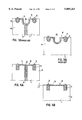
- the inductor 1 which constitutes an essential part of a sealing jaw, normally consists of two parallel conductors 3 disposed in slight spaced apart relationship from one another so that there is, between the conductors 3 which each realise a transverse seal on the flat-laid material tube 2, space to be able to separate the packaging containers from the tube.
- the two conductors 3 are mounted in an electrically insulated carrier body 4.
- Each conductor 3 is designed with a narrows bead or ridge 5 which rises above the surface 8 of the inductor 1.
- the ridge 5 contributes in increasing the pressure on a narrow surface in order further to assist in obtaining a tight and uniform transverse joint seal.
- Both conductors 3 are electrically interconnected to one another and to a high frequency alternating current source (not shown).
- the inductor 1 as shown in FIGS. 1 and 4A and 4B, has transverse conductors 6 and 7 which are placed in the upper surface 8 of the inductor 1.
- the one transverse conductor 6 connects to interjacent ends of the conductors 3, while the other transverse conductor 7 continues in the connection lead 9 of the inductor 1 with an electric insulation layer 10 provided between the connection leads 9.
- the transverse conductors 11 and 12 were disposed within the electrically insulated carrier body 4 so that they were not able to affect the flat-laid tube web 2 which is disposed against the surface 8 of the inductor 1.
- the prior art transverse connections 11 and 12 were moreover located a distance outside the outer defining lines 13 of the flat-laid material tube 2.
- the transverse conductors 6 and 7 disposed on the surface 8 of the inductor 1 coincide with the outer defining lines 13 of the flat-laid material tube 2.
- the flat-laid material tube 2 is to be advanced through the machine such that the outer defining lines 13 coincide with the centre line of the transverse conductors 6, 7, with a tolerance of ⁇ 1.5 mm.
- the two conductors 3 are connected to a high frequency alternating current source (not shown) via the connection leads 9, a high frequency magnetic field occurs around the inductor 1, which generates an induction current in the aluminium foil layer in the flat-laid material tube 2.
- the current induced in the aluminium layer generates heat, and this heat is conducted over to the adjacent thermoplastic layers so that these are caused to soften or melt.
- the prior art inductor 1 is illustrated in FIG. 2 where there are two parallel conductors 3 which continue outside the outer defining lines 13 of the flat-laid material web 2.
- the current induced in the aluminium layer is illustrated in FIG. 2 by means of electrons 14 and the flow direction is illustrated by means of arrows.
- the electrons 14 reach the outer defining line 13 of the flat-laid material web 2, the electrons "pile up” where the metallic layers and there is an almost infinite resistance outside the outer defining line of the metallic layer. In such instance, the current has a tendency to "branch out", i.e.
- the electrons 14 begin, well before the outer defining lines 13 of the flat-laid material tube, to migrate over to the conductor 3 of the other side and, as a result, there will be a poorer seal in that region of the flat-laid material tube which is located most proximal the outer defining lines 13.
- the difference in power output requirement between the edge zones of the flat-laid material tube 2 and the centre zone is illustrated in the diagrams in FIGS. 5-7.
- the left-hand power output block 15 represents the requirement which is necessary for the edge zones of the flat-laid material tube 2 and the right-hand power output block 16 represents the power output requirements of the central zone.
- the region 17 between the broken lines thus represents that region where a tight and durable transverse sealing joint can be obtained across the whole of the flat-laid material tube 2.
- FIG. 6 shows the power output requirement blocks 15 and 16 for a transverse sealing joint in the packaging of, for example, water.
- a relatively wide region 17 will be obtained which can be utilised in the transverse joint sealing.
- FIG. 5 which shows the power output requirement blocks 15, 16 for a viscous product, such as tomato paste
- FIG. 5 which shows the power output requirement blocks 15, 16 for a viscous product, such as tomato paste
- FIG. 5 which shows the power output requirement blocks 15, 16 for a viscous product, such as tomato paste
- a very narrow region 17 which can be utilised for sealing a flat-laid material tube 2 which contains this viscous product.
- the inductor 1 may be heated and the power consumption must be regulated accordingly.
- the temperature of the packed product, the ambient temperature, and also variations in thickness of the packaging material and aluminium foil may result in the narrow power output region 17 being too small to be able to achieve an efficient and tight sealing joint throughout the entire flat-laid packaging material tube 2.
- the present invention offers, as a result of the transverse conductors 6 and 7 lying in the surface 8 of the inductor 1, a control of the current such that, when the electrons 14 reach the outer defining line 13 of the flat-laid material tube, the transverse conductors will "drive” the current further along the outer defining line 13 of the flat-laid material tube 2.
- this gives a sealing pattern which is of rectangular appearance, where the short sides of the rectangle are constituted by the outer defining lines 13 of the flat-laid material tube 2.
- the short side seals which are created by such means have, however, no function as operative seals.
- the width B of the transverse conductors 6, 7 for their adaptation for an inductor 1 for use for viscous pumpable products may be between 5 and 7 mm, preferably 6 mm.
- the depth D of the transverse conductors is selected so as to lie between 0.8 and 1.2 mm, preferably 1 mm.
- the present invention realises, in an apparatus for sealing, an inductor 1 which makes possible sealing of transverse joints enclosing a viscous product and in which it is possible to employ a power output range in which there is no risk of obtaining untight sealing joints in the edge zones most proximal the outer defining lines 13 of the flat-laid material tube 2, or of overheating the thermoplastic layers in the central zone of the flat-laid material tube 2.
Abstract
A method and apparatus for induction sealing of a packaging material which includes a layer of aluminum foil. The apparatus includes an inductor with two parallel slightly spaced apart conductors which are disposed in an electrically insulated carrier portion. The conductors are connected to one another and to a high frequency current source by two transverse conductors. The transverse conductors are placed in the upper surface of the inductor and coincide with the outer defining lines of a flat-laid tube of packaging material.
Description
The present invention relates to an apparatus for sealing thermoplastic coated packaging material including at least one layer of metal foil, preferably aluminium foil (`Alifoil`), the apparatus comprising an inductor which is connectable to a high frequency current source and which displays at least two parallel, slightly spaced-apart conductors, and an electrically insulated carrier portion.
The present invention also relates to a method for sealing a packaging material displaying at least one thermoplastic layer and a layer of metal foil, preferably aluminium foil (`Alifoil`), disposed adjacent the thermoplastic layer, the sealing operation being carried out by means of an apparatus, a so-called inductor, which displays two parallel conductors which are connected to one another and to a high frequency current source, by means of which an electric current of high frequency is induced in the metal foil layer of the packaging material, from which heat generated by the current is conducted to the thermoplastic layer which is caused to melt, mutually united and compressed layers of the packaging material being bonded to one another by fusion of the mutually facing thermoplastic layers for the formation of a tight and durable joint seal.
It has long been known in the packaging industry to employ packaging materials comprising core layers of, for example, paper or paperboard and outer layers of thermoplastic, which outer layers may be sealed to one another by fusion after heating and compression, so as obtain tight and durable sealing joints or seams.
According to one method of production of single-use disposable packages which has been put to large scale use, a web of packaging material is formed into a tube in that the longitudinal edges of the web are united to one another in an overlap joint and the web edges are sealed to one another. The thus formed tube can then be filled with the intended contents, such as, for example, liquid or pumpable foods, whereafter the filled tube is divided into individual packaging containers by transverse sealing of the tube along narrow zones which are applied in uniform spaced apart relationship from one another. Thereafter, the closed tube sections are separated from the rest of the tube, for the formation of individual packaging containers.
The sealing of the packaging material will be considerably facilitated if the packaging material includes a layer of metal foil, preferably aluminium foil, which also constitutes the barrier layer of the packaging material and protects the enclosed product. By inducing, in the aluminium layer of the packaging material, electric currents with the aid of a so-called inductor or coil which basically consists of an electric conductor formed into the desired configuration and forming one or more coil turns which are connected to a current source which supplies the coil with high frequency alternating current. Frequencies of 500 kHz and 1.8 MHz are generally employed.
When a high frequency current is passed through the coil or inductor, a high frequency magnetic field occurs around the coil or inductor and, if the coil is placed adjacent a material which includes a metal layer, induction currents are induced in this metal layer which give rise to a heat generation in those parts where the current is led. The heat generated in the metal foil layer is readily conducted over to adjacent layers of thermoplastic such as, for example, polyethylene, which are thereby caused to soften or melt. If the material layers in which heat is generated are compressed against another similar material layer with a thermoplastic coating, the thermoplastic coatings will, in the region of the heating, fuse together for the formation of a tight and durable seal joint.
In order to concentrate the magnetic field and obtain narrow heating zones, it is appropriate to dispose the inductor as close to the metal layer as possible, i.e. the inductor should be pressed against the material which is to be sealed. In order further to improve the sealing joint, the inductor may be designed so that the surface of the inductor facing towards the packaging material is provided, along a part of its surface, with a projecting ridge in order further to amplify the sealing pressure. An inductor according to the above description is disclosed in, for example, Swedish Patent Specification SE-451 974.
One problem inherent in all inductors of the above-outlined type is, however, the difficulty in obtaining a uniform seal transversely across the entire surface which is constituted by the flat-laid packaging material tube so that both the central zone of the transverse seal and the edge zone will have a tight and durable seal. When the induced current reaches the edge of the packaging material web, there is nothing to conduct the current further, with the result that, when the current approaches the packaging material edge, it deflects gradually off to the opposite side where the current is counter-directed. There will thus be a lower current density and thereby lower power output density furthest out towards the edge of the packaging material. Previously, this has been compensated for by increasing the power output so that it is sufficient also to seal right out to the outermost edge of the packaging material.
For packed products of a liquid nature, such as, for instance water, juice or milk, a power output increase to compensate for reduced power output density at the edge of the material web functions quite satisfactorily, but for thick or viscous products such as, for example, tomato puree or paste and the like, it has proved extremely difficult to obtain a tight and uniform seal joint transversely across the entire packaging material tube, since it is not possible to raise the power output limitlessly. An excessive high power output will negatively affect the central region of the packaging material tube, in that the thermoplastic is converted in plastic droplets, so-called plastic spray, which may affect the tightness and quality of the finished package.
One object of the present invention is to realise an inductor which provides a uniform and tight seal joint along the entire transverse seal and which may also be employed when viscous products are to be packed in the material tube.
A further object of the present invention is to realise an inductor which can work at a power output level which gives a seal of as equally good quality in the edge of the packaging material web as in its central region.
These and other objects have been attained according to the present invention in that the apparatus of the type described by way of introduction has been given the characterizing feature that the two conductors are connected to one another and to the current source by means of transverse conductors placed in the upper surface of the inductor and arranged such that they coincide with the outer defining lines of the packaging material.
These and other objects have further been attained according to the present invention in that the method of the type described by way of introduction has been given the characterizing feature that transverse conductors placed in the upper surface of the inductor coincide with the outer defining lines of the packaging material, the transverse conductors leading the current between the two main conductors.
Preferred embodiments of the present invention have further been given the characterizing features as set forth in the appended subclaims.
One preferred embodiment of the present invention will now be described in greater detail hereinbelow, with particular reference to the accompanying Drawings, in which:
FIG. 1 shows an inductor according to the present invention;
FIG. 2 shows the state of the art of inductors;
FIGS. 3A and 3B show, partly in section, a state-of-the-art inductor;
FIGS. 4A and 4B show, partly in section, an inductor according to the present invention;
FIG. 5 is a diagram showing the sealing operation for viscous products according to the state of the art;
FIG. 6 is a diagram showing the sealing operation for liquid products according to the state of the art; and
FIG. 7 is a diagram showing the sealing operation according to the present invention.
A sealing apparatus or inductor 1 of the type shown in FIG. 1 is intended to be mounted in a machine part included in a filling machine for liquid or pumpable foods. The desired sealing movement and desired sealing pressure are imparted to the machine part. The machine part, which is often called a sealing jaw, is brought--in a relative movement--against a so-called counter jaw which may also be movable as well. The sealing operation is carried out between the sealing jaw and the counter jaw.
A packaging material web is led through the filling machine, the web being of the type which is usual in packaging material containers of the single-use disposable type, i.e. the packaging material web normally has a core layer of paper or paperboard to which are laminated different layers of thermoplastic, constituting the outer layers of the packaging material. The packaging material also includes a barrier layer of metal foil, preferably aluminium foil.
The packaging material web is given tubular form in the filling machine and, by an overlap joint, the two material edges are sealed to each other. The thus formed tube is filled with the intended contents and, thereafter, the tube is transversely sealed across a flat-laid material tube 2. The transverse joint seals are placed in uniform spaced apart relationship from one another, so that a predetermined quantity of contents is enclosed in individual tube sections. The individual tube sections are thereafter separated for forming individual packaging containers. By orienting the transverse sealing joints in different ways, for example by displacing the sealing jaws through 90° between each transverse seal, a tetrahedral package will be obtained, while, with the same orientation of the sealing jaws, a packaging container blank will be obtained which, by subsequent folding and sealing, may be given parallelepipedic configuration.
The inductor 1, which constitutes an essential part of a sealing jaw, normally consists of two parallel conductors 3 disposed in slight spaced apart relationship from one another so that there is, between the conductors 3 which each realise a transverse seal on the flat-laid material tube 2, space to be able to separate the packaging containers from the tube. The two conductors 3 are mounted in an electrically insulated carrier body 4. Each conductor 3 is designed with a narrows bead or ridge 5 which rises above the surface 8 of the inductor 1. The ridge 5 contributes in increasing the pressure on a narrow surface in order further to assist in obtaining a tight and uniform transverse joint seal. Both conductors 3 are electrically interconnected to one another and to a high frequency alternating current source (not shown).
The inductor 1 according to the invention, as shown in FIGS. 1 and 4A and 4B, has transverse conductors 6 and 7 which are placed in the upper surface 8 of the inductor 1. The one transverse conductor 6 connects to interjacent ends of the conductors 3, while the other transverse conductor 7 continues in the connection lead 9 of the inductor 1 with an electric insulation layer 10 provided between the connection leads 9. In prior art inductors 1 as shown in FIGS. 3A and 3B, the transverse conductors 11 and 12 were disposed within the electrically insulated carrier body 4 so that they were not able to affect the flat-laid tube web 2 which is disposed against the surface 8 of the inductor 1. The prior art transverse connections 11 and 12 were moreover located a distance outside the outer defining lines 13 of the flat-laid material tube 2.
In the present invention, the transverse conductors 6 and 7 disposed on the surface 8 of the inductor 1 coincide with the outer defining lines 13 of the flat-laid material tube 2. In the preferred embodiment, the flat-laid material tube 2 is to be advanced through the machine such that the outer defining lines 13 coincide with the centre line of the transverse conductors 6, 7, with a tolerance of ±1.5 mm.
Since the two conductors 3 are connected to a high frequency alternating current source (not shown) via the connection leads 9, a high frequency magnetic field occurs around the inductor 1, which generates an induction current in the aluminium foil layer in the flat-laid material tube 2. The current induced in the aluminium layer generates heat, and this heat is conducted over to the adjacent thermoplastic layers so that these are caused to soften or melt. By compressing together two such thermoplastic layers in the flat-laid material tube 2, a tight transverse joint seal will be obtained.
The prior art inductor 1 is illustrated in FIG. 2 where there are two parallel conductors 3 which continue outside the outer defining lines 13 of the flat-laid material web 2. The current induced in the aluminium layer is illustrated in FIG. 2 by means of electrons 14 and the flow direction is illustrated by means of arrows. When the electrons 14 reach the outer defining line 13 of the flat-laid material web 2, the electrons "pile up" where the metallic layers and there is an almost infinite resistance outside the outer defining line of the metallic layer. In such instance, the current has a tendency to "branch out", i.e. the electrons 14 begin, well before the outer defining lines 13 of the flat-laid material tube, to migrate over to the conductor 3 of the other side and, as a result, there will be a poorer seal in that region of the flat-laid material tube which is located most proximal the outer defining lines 13.
The difference in power output requirement between the edge zones of the flat-laid material tube 2 and the centre zone is illustrated in the diagrams in FIGS. 5-7. In each diagram, the left-hand power output block 15 represents the requirement which is necessary for the edge zones of the flat-laid material tube 2 and the right-hand power output block 16 represents the power output requirements of the central zone. The region 17 between the broken lines thus represents that region where a tight and durable transverse sealing joint can be obtained across the whole of the flat-laid material tube 2.
FIG. 6 shows the power output requirement blocks 15 and 16 for a transverse sealing joint in the packaging of, for example, water. In this case, a relatively wide region 17 will be obtained which can be utilised in the transverse joint sealing. In FIG. 5, which shows the power output requirement blocks 15, 16 for a viscous product, such as tomato paste, there will, on the other hand, be a very narrow region 17 which can be utilised for sealing a flat-laid material tube 2 which contains this viscous product. There are also products which it is desirable to pack in single-use disposable packages of the above-described type, but for which there is no overlapping power output region 17. This implies in practice that it has hitherto been almost impossible to seal packages containing such a product in a satisfactory manner.
It may be difficult to keep to the narrow region 17 when, after a certain time's production, the inductor 1 is heated and the power consumption must be regulated accordingly. In addition, the temperature of the packed product, the ambient temperature, and also variations in thickness of the packaging material and aluminium foil may result in the narrow power output region 17 being too small to be able to achieve an efficient and tight sealing joint throughout the entire flat-laid packaging material tube 2.
If power consumption falls below the region 17 shown by broken lines, there is a risk of obtaining a transverse joint seal of the flat-laid material tube 2 in which both of the edge zones close to the outer defining lines 13 are not sufficiently tight. If, on the other hand, power consumption is above the zone illustrated by broken lines, there is a risk of overheating the thermoplastic layer in the central zone of the flat-laid material tube 2, such that the thermoplastic forms droplets, so-called plastic spray, which, in a later treatment or handling of the finished packaging container, may cause mechanical damage to the inner plastic layer of the packaging material, with consequential untightness of the package.
To avoid the above problems which the prior art inductors 1 gave rise to, in particular in the packing of viscous products, the present invention offers, as a result of the transverse conductors 6 and 7 lying in the surface 8 of the inductor 1, a control of the current such that, when the electrons 14 reach the outer defining line 13 of the flat-laid material tube, the transverse conductors will "drive" the current further along the outer defining line 13 of the flat-laid material tube 2. In practice, this gives a sealing pattern which is of rectangular appearance, where the short sides of the rectangle are constituted by the outer defining lines 13 of the flat-laid material tube 2. The short side seals which are created by such means have, however, no function as operative seals.
By meticulous and accurate design and dimensioning of the transverse conductors, the attempt is made (as shown in FIG. 7) to place the power output requirement for both the central zone of the flat-laid material tube and its edge zones at the same interval or region 17. This applies to both liquid products and pumpable products. For example, the width B of the transverse conductors 6, 7 for their adaptation for an inductor 1 for use for viscous pumpable products, may be between 5 and 7 mm, preferably 6 mm. The depth D of the transverse conductors is selected so as to lie between 0.8 and 1.2 mm, preferably 1 mm. At the same time, it is important that the outer defining lines 13 of the flat-laid material tube 2 coincide as accurately as possible with the centre lines of the transverse conductors 6, 7. In the preferred embodiment, there is a tolerance of ±1.5 mm.
As will have been apparent from the foregoing description, the present invention realises, in an apparatus for sealing, an inductor 1 which makes possible sealing of transverse joints enclosing a viscous product and in which it is possible to employ a power output range in which there is no risk of obtaining untight sealing joints in the edge zones most proximal the outer defining lines 13 of the flat-laid material tube 2, or of overheating the thermoplastic layers in the central zone of the flat-laid material tube 2.
Claims (6)
1. A sealing system comprising:
a thermoplastic coated packaging material including at least one layer of metal foil and having outer edges which define outer lines of the packaging material,
an inductor connectable to a high frequency current source, said inductor including at least two parallel, slightly spaced-apart conductors, an electrically insulated carrier portion, and a first and a second transverse conductor;
wherein the two parallel conductors are connected to one another and to said current source by means of the transverse conductors; and
wherein the transverse conductors are placed in an upper surface of the inductor and disposed such that they coincide with the outer defining lines of the packaging material to be sealed.
2. The system as claimed in claim 1, wherein the outer defining lines of the packaging material coincide with a centre line of the transverse conductors ±1.5 mm.
3. The system as claimed in claim 1, wherein the transverse conductors have a width and a depth dimensioned such that the power output consumption for sealing an edge zone of the packaging material is equal to the power output consumption for sealing a central zone of the packaging material.
4. A method of sealing a packaging material the sealing method comprising:
providing a packaging material web including at least one layer of thermoplastic material, a layer of metal foil extending thereover, and having outer edges which define outer lines of the packaging material web;
providing an inductor including two parallel conductors connected to one another and to a high frequency current source,
inducing an electric current of high frequency in the metal foil layer of the packaging material, from which heat generated by the current is conducted to the thermoplastic layer which is caused to melt, mutually united and compressed layers of the packaging material being bonded to one another by fusion of the mutually facing thermoplastic layers for the formation of a tight and durable joint seal, p1 providing transverse conductors in an upper surface of the inductor and positioning the transverse conductors so as to coincide with the outer defining lines of the packaging material, said transverse conductors leading the current between the two main conductors.
5. The method as claimed in claim 4, wherein a rectangular sealing pattern occurs where the short sides of the rectangle consist of the outer defining lines of the packaging material.
6. An inductor sealing system comprising:
a thermoplastic coated packaging material web including at least one layer of metal foil and having outer edges which define outer lines of the packaging material,
at least two parallel, slightly spaced-apart conductors;
an electrically insulated carrier portion; and
a first and a second transverse conductor;
wherein the two parallel conductors are connected to one another and to a current source by the transverse conductors; and
wherein the transverse conductors are positioned within the inductor such that they coincide with outer edges of the packaging material web.
Applications Claiming Priority (2)
| Application Number | Priority Date | Filing Date | Title |
|---|---|---|---|
| SE9601067A SE506190C2 (en) | 1996-03-20 | 1996-03-20 | Apparatus and method for induction sealing of thermoplastic coated packaging material |
| SE9601067 | 1996-03-20 |
Publications (1)
| Publication Number | Publication Date |
|---|---|
| US5889263A true US5889263A (en) | 1999-03-30 |
Family
ID=20401866
Family Applications (1)
| Application Number | Title | Priority Date | Filing Date |
|---|---|---|---|
| US08/820,939 Expired - Lifetime US5889263A (en) | 1996-03-20 | 1997-03-19 | Apparatus and a method for induction sealing |
Country Status (13)
| Country | Link |
|---|---|
| US (1) | US5889263A (en) |
| EP (1) | EP0796718B1 (en) |
| AT (1) | ATE192691T1 (en) |
| BR (1) | BR9701400A (en) |
| DE (1) | DE69701914T2 (en) |
| DK (1) | DK0796718T3 (en) |
| ES (1) | ES2146434T3 (en) |
| GR (1) | GR3033228T3 (en) |
| HU (1) | HU218894B (en) |
| ID (1) | ID19822A (en) |
| PT (1) | PT796718E (en) |
| RU (1) | RU2179944C2 (en) |
| SE (1) | SE506190C2 (en) |
Cited By (25)
| Publication number | Priority date | Publication date | Assignee | Title |
|---|---|---|---|---|
| US6725630B2 (en) | 2001-11-15 | 2004-04-27 | Sonoco Development, Inc. | Method for induction sealing a plastic part to a composite container |
| WO2004054786A1 (en) * | 2002-12-13 | 2004-07-01 | Tetra Laval Holdings & Finance S.A. | Method and device for manufacturing packages |
| US20040182046A1 (en) * | 2001-06-18 | 2004-09-23 | Andrea Babini | Induction sealing device for heat sealing packaging material |
| US20050165929A1 (en) * | 2000-02-04 | 2005-07-28 | Ricoh Company, Ltd. | Method and system for maintaining a business office appliance through log files |
| WO2006006900A1 (en) * | 2004-07-08 | 2006-01-19 | Tetra Laval Holdings & Finance S.A. | A method and an apparatus for retrosealing of packaging containers |
| US7003934B1 (en) * | 1998-10-30 | 2006-02-28 | Tetra Laval Holdings & Finance S.A. | Heat seal device |
| US20060242928A1 (en) * | 2003-03-28 | 2006-11-02 | Tetra Laval Holdings & Finance Sa | Induction sealing device and method which may be used for producing packages of pourable food products |
| US20070017189A1 (en) * | 2003-10-14 | 2007-01-25 | Tetra Laval Holdings & Finance S.A. | Packing filling machine and lateral sealing machine |
| US20070033530A1 (en) * | 1999-05-13 | 2007-02-08 | Tetsuro Motoyama | Application unit monitoring and reporting system and method |
| US20100180545A1 (en) * | 2007-06-28 | 2010-07-22 | Tetra Laval Holdings & Finance S.A. | Induction sealing device for heat sealing packaging material for producing sealed packages of pourable food products |
| WO2013002702A1 (en) * | 2011-05-27 | 2013-01-03 | Å&R Carton Lund Ab | Method for manufacturing a container comprising sealing of container parts |
| US8366859B2 (en) | 2004-12-14 | 2013-02-05 | Tetra Laval Holdings & Finance S.A. | Method and device for sealing |
| RU2588140C2 (en) * | 2011-05-27 | 2016-06-27 | О Энд Р Картон Лунд Аб | Method of producing container including container parts seal |
| CN106232327A (en) * | 2014-04-16 | 2016-12-14 | 利乐拉瓦尔集团及财务有限公司 | Induction sealing device and the method using this induction sealing device sealing and packing material |
| US20180345592A1 (en) * | 2015-11-27 | 2018-12-06 | Tetra Laval Holdings & Finance S.A. | A sealing device with increased robustness |
| US10350832B2 (en) | 2014-11-24 | 2019-07-16 | Tetra Laval Holdings & Finance S.A. | Simplified transversal induction sealing device |
| US10899082B2 (en) | 2017-07-17 | 2021-01-26 | Tetra Laval Holdings & Finance S.A. | Inductor coil for induction welding of a packaging material |
| US11370571B2 (en) | 2017-07-18 | 2022-06-28 | Tetra Laval Holdings & Finance S.A. | Induction sealing device |
| US11534985B2 (en) | 2016-05-02 | 2022-12-27 | Tetra Laval Holdings & Finance S.A. | Induction sealing system |
| US11548238B2 (en) | 2018-09-10 | 2023-01-10 | Tetra Laval Holdings & Finance S.A. | Method for forming a tube and a method and a packaging machine for forming a package |
| US11554555B2 (en) | 2017-05-30 | 2023-01-17 | Tetra Laval Holdings & Finance S.A. | Apparatus for sealing the top of a package for a food product and system for forming and filling a food package |
| US11745457B2 (en) | 2016-06-03 | 2023-09-05 | Lancan Systems Inc. | Method and apparatus for forming containers |
| US11772352B2 (en) | 2020-04-20 | 2023-10-03 | H. J. Paul Langen | Method and apparatus for forming containers |
| US11780199B2 (en) | 2016-06-03 | 2023-10-10 | Lancan Systems Inc. | Method and apparatus for forming containers |
| US11820540B2 (en) | 2018-09-11 | 2023-11-21 | Tetra Laval Holdings & Finance S.A. | Packaging apparatus for forming sealed packages |
Citations (9)
| Publication number | Priority date | Publication date | Assignee | Title |
|---|---|---|---|---|
| US2620415A (en) * | 1949-05-04 | 1952-12-02 | Ohio Brass Co | Knife blade switch |
| US3399258A (en) * | 1965-09-29 | 1968-08-27 | Coats & Clark | Method of automatically producing molded travelers with wear resistant inserts |
| US3548140A (en) * | 1967-07-25 | 1970-12-15 | Continental Can Co | Method and apparatus for sealing containers using heat activated magnetic sealing compound |
| US4230923A (en) * | 1977-06-20 | 1980-10-28 | Ab Akerlund & Rausing | Device for induction welding |
| US4637199A (en) * | 1985-01-30 | 1987-01-20 | International Paper Company | Induction sealing of paperboard |
| US4704509A (en) * | 1985-08-22 | 1987-11-03 | Tetra Pak International Ab | Induction apparatus and method for sealing of thermoplastic coated packing material |
| US5117613A (en) * | 1991-04-11 | 1992-06-02 | Tocco, Inc. | Induction heating and package sealing system and method |
| US5250140A (en) * | 1990-10-19 | 1993-10-05 | Shikoku Kakoki Co., Ltd. | Device having raised side edge portions for heat-sealing tubular packaging material |
| US5649407A (en) * | 1993-09-08 | 1997-07-22 | Tetra Laval Holdings & Finance S.A. | Apparatus for sealing thermoplastic-coated packaging material |
-
1996
- 1996-03-20 SE SE9601067A patent/SE506190C2/en not_active IP Right Cessation
-
1997
- 1997-03-18 PT PT97104585T patent/PT796718E/en unknown
- 1997-03-18 DK DK97104585T patent/DK0796718T3/en active
- 1997-03-18 EP EP19970104585 patent/EP0796718B1/en not_active Expired - Lifetime
- 1997-03-18 AT AT97104585T patent/ATE192691T1/en active
- 1997-03-18 ES ES97104585T patent/ES2146434T3/en not_active Expired - Lifetime
- 1997-03-18 DE DE1997601914 patent/DE69701914T2/en not_active Expired - Lifetime
- 1997-03-19 US US08/820,939 patent/US5889263A/en not_active Expired - Lifetime
- 1997-03-19 RU RU97104179A patent/RU2179944C2/en not_active IP Right Cessation
- 1997-03-19 HU HU9700611A patent/HU218894B/en not_active IP Right Cessation
- 1997-03-20 ID ID970901A patent/ID19822A/en unknown
- 1997-03-20 BR BR9701400A patent/BR9701400A/en not_active IP Right Cessation
-
2000
- 2000-05-11 GR GR20000400875T patent/GR3033228T3/en unknown
Patent Citations (9)
| Publication number | Priority date | Publication date | Assignee | Title |
|---|---|---|---|---|
| US2620415A (en) * | 1949-05-04 | 1952-12-02 | Ohio Brass Co | Knife blade switch |
| US3399258A (en) * | 1965-09-29 | 1968-08-27 | Coats & Clark | Method of automatically producing molded travelers with wear resistant inserts |
| US3548140A (en) * | 1967-07-25 | 1970-12-15 | Continental Can Co | Method and apparatus for sealing containers using heat activated magnetic sealing compound |
| US4230923A (en) * | 1977-06-20 | 1980-10-28 | Ab Akerlund & Rausing | Device for induction welding |
| US4637199A (en) * | 1985-01-30 | 1987-01-20 | International Paper Company | Induction sealing of paperboard |
| US4704509A (en) * | 1985-08-22 | 1987-11-03 | Tetra Pak International Ab | Induction apparatus and method for sealing of thermoplastic coated packing material |
| US5250140A (en) * | 1990-10-19 | 1993-10-05 | Shikoku Kakoki Co., Ltd. | Device having raised side edge portions for heat-sealing tubular packaging material |
| US5117613A (en) * | 1991-04-11 | 1992-06-02 | Tocco, Inc. | Induction heating and package sealing system and method |
| US5649407A (en) * | 1993-09-08 | 1997-07-22 | Tetra Laval Holdings & Finance S.A. | Apparatus for sealing thermoplastic-coated packaging material |
Cited By (39)
| Publication number | Priority date | Publication date | Assignee | Title |
|---|---|---|---|---|
| US7003934B1 (en) * | 1998-10-30 | 2006-02-28 | Tetra Laval Holdings & Finance S.A. | Heat seal device |
| US20070033530A1 (en) * | 1999-05-13 | 2007-02-08 | Tetsuro Motoyama | Application unit monitoring and reporting system and method |
| US20050165929A1 (en) * | 2000-02-04 | 2005-07-28 | Ricoh Company, Ltd. | Method and system for maintaining a business office appliance through log files |
| US20040182046A1 (en) * | 2001-06-18 | 2004-09-23 | Andrea Babini | Induction sealing device for heat sealing packaging material |
| US7059100B2 (en) * | 2001-06-18 | 2006-06-13 | Tetra Laval Holdings & Finance Sa | Induction sealing device for heat sealing packaging material |
| US6725630B2 (en) | 2001-11-15 | 2004-04-27 | Sonoco Development, Inc. | Method for induction sealing a plastic part to a composite container |
| WO2004054786A1 (en) * | 2002-12-13 | 2004-07-01 | Tetra Laval Holdings & Finance S.A. | Method and device for manufacturing packages |
| KR101000239B1 (en) | 2002-12-13 | 2010-12-10 | 테트라 라발 홀딩스 앤드 피낭스 소시에떼아노님 | Method and device for manufacturing packages |
| US20060049179A1 (en) * | 2002-12-13 | 2006-03-09 | Tetra Laval Holdings & Finance S.A. | Method and device for manufacturing packages |
| US7129450B2 (en) | 2002-12-13 | 2006-10-31 | Tetra Laval Holdings & Finance S.A. | Method and device for manufacturing packages |
| CN100400270C (en) * | 2002-12-13 | 2008-07-09 | 利乐拉瓦尔集团及财务有限公司 | Method and device for manufacturing packages |
| US7538302B2 (en) | 2003-03-28 | 2009-05-26 | Tetra Laval Holdings & Finance Sa | Induction sealing device and method which may be used for producing packages of pourable food products |
| US20060242928A1 (en) * | 2003-03-28 | 2006-11-02 | Tetra Laval Holdings & Finance Sa | Induction sealing device and method which may be used for producing packages of pourable food products |
| US20070017189A1 (en) * | 2003-10-14 | 2007-01-25 | Tetra Laval Holdings & Finance S.A. | Packing filling machine and lateral sealing machine |
| US7484347B2 (en) * | 2003-10-14 | 2009-02-03 | Tetra Laval Holdings & Finance S.A. | Packaging filling apparatus and transversal sealing apparatus |
| US20080067168A1 (en) * | 2004-07-08 | 2008-03-20 | Tetra Laval Holdings & Finance S.A. | Method and an Apparatus for Retrosealing of Packaging Containers |
| CN100548818C (en) * | 2004-07-08 | 2009-10-14 | 利乐拉瓦尔集团及财务有限公司 | The method and apparatus that is used for contrary sealed package |
| US7638742B2 (en) | 2004-07-08 | 2009-12-29 | Tetra Laval Holdings & Finance S.A. | Method and an apparatus for retrosealing of packaging containers using induction heating |
| WO2006006900A1 (en) * | 2004-07-08 | 2006-01-19 | Tetra Laval Holdings & Finance S.A. | A method and an apparatus for retrosealing of packaging containers |
| US8366859B2 (en) | 2004-12-14 | 2013-02-05 | Tetra Laval Holdings & Finance S.A. | Method and device for sealing |
| US20100180545A1 (en) * | 2007-06-28 | 2010-07-22 | Tetra Laval Holdings & Finance S.A. | Induction sealing device for heat sealing packaging material for producing sealed packages of pourable food products |
| US9174754B2 (en) * | 2007-06-28 | 2015-11-03 | Tetra Laval Holdings & Finance S.A. | Induction sealing device for heat sealing packaging material for producing sealed packages of pourable food products |
| RU2588140C2 (en) * | 2011-05-27 | 2016-06-27 | О Энд Р Картон Лунд Аб | Method of producing container including container parts seal |
| WO2013002702A1 (en) * | 2011-05-27 | 2013-01-03 | Å&R Carton Lund Ab | Method for manufacturing a container comprising sealing of container parts |
| US10358243B2 (en) | 2014-04-16 | 2019-07-23 | Tetra Laval Holdings & Finance S.A. | Induction sealing device and method of sealing a packaging material using said induction sealing device |
| CN106232327A (en) * | 2014-04-16 | 2016-12-14 | 利乐拉瓦尔集团及财务有限公司 | Induction sealing device and the method using this induction sealing device sealing and packing material |
| CN106232327B (en) * | 2014-04-16 | 2019-04-02 | 利乐拉瓦尔集团及财务有限公司 | Induction sealing device and the method for using the induction sealing device sealing and packing material |
| US10350832B2 (en) | 2014-11-24 | 2019-07-16 | Tetra Laval Holdings & Finance S.A. | Simplified transversal induction sealing device |
| US20180345592A1 (en) * | 2015-11-27 | 2018-12-06 | Tetra Laval Holdings & Finance S.A. | A sealing device with increased robustness |
| US10994495B2 (en) * | 2015-11-27 | 2021-05-04 | Tetra Laval Holdings & Finance S.A. | Sealing device with increased robustness |
| US11534985B2 (en) | 2016-05-02 | 2022-12-27 | Tetra Laval Holdings & Finance S.A. | Induction sealing system |
| US11780199B2 (en) | 2016-06-03 | 2023-10-10 | Lancan Systems Inc. | Method and apparatus for forming containers |
| US11745457B2 (en) | 2016-06-03 | 2023-09-05 | Lancan Systems Inc. | Method and apparatus for forming containers |
| US11554555B2 (en) | 2017-05-30 | 2023-01-17 | Tetra Laval Holdings & Finance S.A. | Apparatus for sealing the top of a package for a food product and system for forming and filling a food package |
| US10899082B2 (en) | 2017-07-17 | 2021-01-26 | Tetra Laval Holdings & Finance S.A. | Inductor coil for induction welding of a packaging material |
| US11370571B2 (en) | 2017-07-18 | 2022-06-28 | Tetra Laval Holdings & Finance S.A. | Induction sealing device |
| US11548238B2 (en) | 2018-09-10 | 2023-01-10 | Tetra Laval Holdings & Finance S.A. | Method for forming a tube and a method and a packaging machine for forming a package |
| US11820540B2 (en) | 2018-09-11 | 2023-11-21 | Tetra Laval Holdings & Finance S.A. | Packaging apparatus for forming sealed packages |
| US11772352B2 (en) | 2020-04-20 | 2023-10-03 | H. J. Paul Langen | Method and apparatus for forming containers |
Also Published As
| Publication number | Publication date |
|---|---|
| PT796718E (en) | 2000-08-31 |
| SE9601067D0 (en) | 1996-03-20 |
| RU2179944C2 (en) | 2002-02-27 |
| ID19822A (en) | 1998-08-06 |
| SE506190C2 (en) | 1997-11-17 |
| DK0796718T3 (en) | 2000-08-07 |
| EP0796718B1 (en) | 2000-05-10 |
| HU218894B (en) | 2000-12-28 |
| HUP9700611A2 (en) | 1997-12-29 |
| DE69701914D1 (en) | 2000-06-15 |
| BR9701400A (en) | 1998-11-03 |
| GR3033228T3 (en) | 2000-08-31 |
| SE9601067L (en) | 1997-09-21 |
| ATE192691T1 (en) | 2000-05-15 |
| HUP9700611A3 (en) | 1998-04-28 |
| HU9700611D0 (en) | 1997-05-28 |
| ES2146434T3 (en) | 2000-08-01 |
| EP0796718A1 (en) | 1997-09-24 |
| DE69701914T2 (en) | 2000-12-07 |
Similar Documents
| Publication | Publication Date | Title |
|---|---|---|
| US5889263A (en) | Apparatus and a method for induction sealing | |
| US4704509A (en) | Induction apparatus and method for sealing of thermoplastic coated packing material | |
| EP0642914B1 (en) | An apparatus for sealing thermoplastic-coated packaging material | |
| US3864186A (en) | Method for induction sealing packaging material | |
| AU621205B2 (en) | An arrangement for continuous induction welding | |
| US7348525B2 (en) | Sealing jaw | |
| US10358243B2 (en) | Induction sealing device and method of sealing a packaging material using said induction sealing device | |
| JP2501777B2 (en) | Equipment for heat-sealing packaging laminates | |
| US6894256B2 (en) | Apparatus in the production of a package or a packaging material | |
| US5260535A (en) | Apparatus for induction welding | |
| CA1225049A (en) | Joint on packing containers and a method and arrangement for the manufacture of the same | |
| EP0883546A1 (en) | Sealing apparatus | |
| JPH08230834A (en) | Seal device | |
| RU2196089C2 (en) | Sealing device for creating zone of sealing (versions) and method of creating such zone | |
| CN217865140U (en) | Induction heating sealing device, induction heating sealing system and packaging production machine | |
| US20180133976A1 (en) | Induction heating sealing device |
Legal Events
| Date | Code | Title | Description |
|---|---|---|---|
| AS | Assignment |
Owner name: TETRA LAVAL HOLDINGS & FINANCE S.A., SWITZERLAND Free format text: ASSIGNMENT OF ASSIGNORS INTEREST;ASSIGNOR:ANDERSSON, MIKAEL;REEL/FRAME:008675/0625 Effective date: 19970413 |
|
| STCF | Information on status: patent grant |
Free format text: PATENTED CASE |
|
| FEPP | Fee payment procedure |
Free format text: PAYOR NUMBER ASSIGNED (ORIGINAL EVENT CODE: ASPN); ENTITY STATUS OF PATENT OWNER: LARGE ENTITY |
|
| FPAY | Fee payment |
Year of fee payment: 4 |
|
| REMI | Maintenance fee reminder mailed | ||
| FPAY | Fee payment |
Year of fee payment: 8 |
|
| FPAY | Fee payment |
Year of fee payment: 12 |