US5887640A - Apparatus and method for semi-solid material production - Google Patents
Apparatus and method for semi-solid material production Download PDFInfo
- Publication number
- US5887640A US5887640A US08/726,099 US72609996A US5887640A US 5887640 A US5887640 A US 5887640A US 72609996 A US72609996 A US 72609996A US 5887640 A US5887640 A US 5887640A
- Authority
- US
- United States
- Prior art keywords
- semi
- solid material
- container
- chamber
- solid
- Prior art date
- Legal status (The legal status is an assumption and is not a legal conclusion. Google has not performed a legal analysis and makes no representation as to the accuracy of the status listed.)
- Expired - Fee Related
Links
Images


Classifications
-
- C—CHEMISTRY; METALLURGY
- C22—METALLURGY; FERROUS OR NON-FERROUS ALLOYS; TREATMENT OF ALLOYS OR NON-FERROUS METALS
- C22C—ALLOYS
- C22C1/00—Making non-ferrous alloys
-
- B—PERFORMING OPERATIONS; TRANSPORTING
- B22—CASTING; POWDER METALLURGY
- B22D—CASTING OF METALS; CASTING OF OTHER SUBSTANCES BY THE SAME PROCESSES OR DEVICES
- B22D1/00—Treatment of fused masses in the ladle or the supply runners before casting
-
- B—PERFORMING OPERATIONS; TRANSPORTING
- B22—CASTING; POWDER METALLURGY
- B22D—CASTING OF METALS; CASTING OF OTHER SUBSTANCES BY THE SAME PROCESSES OR DEVICES
- B22D17/00—Pressure die casting or injection die casting, i.e. casting in which the metal is forced into a mould under high pressure
- B22D17/007—Semi-solid pressure die casting
-
- Y—GENERAL TAGGING OF NEW TECHNOLOGICAL DEVELOPMENTS; GENERAL TAGGING OF CROSS-SECTIONAL TECHNOLOGIES SPANNING OVER SEVERAL SECTIONS OF THE IPC; TECHNICAL SUBJECTS COVERED BY FORMER USPC CROSS-REFERENCE ART COLLECTIONS [XRACs] AND DIGESTS
- Y10—TECHNICAL SUBJECTS COVERED BY FORMER USPC
- Y10S—TECHNICAL SUBJECTS COVERED BY FORMER USPC CROSS-REFERENCE ART COLLECTIONS [XRACs] AND DIGESTS
- Y10S164/00—Metal founding
- Y10S164/90—Rheo-casting
Definitions
- the present invention relates generally to producing and delivering a semi-solid material slurry for use in material forming processes.
- the invention relates to an apparatus for producing a substantially non-dendritic semi-solid material slurry suitable for use in a molding or casting apparatus.
- Slurry casting or rheocasting is a procedure in which molten material is subjected to vigorous agitation as it undergoes solidification.
- dendritic structures form within the material that is solidifying.
- a dendritic structure is a solidified particle shaped like an elongated stem having transverse branches. Vigorous agitation of materials, especially metals, during solidification eliminates at least some dendritic structures. Such agitation shears the tips of the solidifying dendritic structures, thereby reducing dendrite formation.
- the resulting material slurry is a solid-liquid composition, composed of solid, relatively fine, non-dendritic particles in a liquid matrix (hereinafter referred to as a semi-solid material).
- the prior art contains many methods and apparatuses used in the formation of semi-solid materials. For example, there are two basic methods of effectuating vigorous agitation. One method is mechanical stirring. This method is exemplified by U.S. Pat. No. 3,951,651 to Mehrabian et al. which discloses rotating blades within a rotating crucible. The second method of agitation is accomplished with electromagnetic stirring. An example of this method is disclosed in U.S. Pat. No. 4,229,210 to Winter et al., which is incorporated herein by reference. Winter et al. disclose using either AC induction or pulsed DC magnetic fields to produce indirect stirring of the semi-solid.
- the Flemings et al. process discloses a single agitation means. Thorough and complete agitation is necessary to maximize the semi-solid characteristics described above. Third, the Flemings et al. process is lacking an effective transfer means and flow regulation from the agitation zone to a casting apparatus. Additional difficulties with the Flemings process, and improvements thereupon, will be apparent from the detailed description below.
- a primary object of the present invention is to provide semi-solid material formation suitable for fashioning directly into a component.
- Another object of the present invention is to provide a more efficient and cost-effective semi-solid material formation process.
- Yet another object of the present invention is to provide an apparatus and a process for forming semi-solid material and maintaining the semi-solid material under substantially isothermal conditions.
- An additional object of the present invention is to provide formation of semi-solid material suitable for component formation without a solidification and reheating step.
- Still another object of the present invention is to provide a process and apparatus for semi-solid material formation with improved shearing and agitation.
- the present invention provides a method and apparatus for producing a semi-solid material suitable for forming directly into a component comprising a source of molten material, a container for receiving the molten material, thermal control means mounted to the container for controlling the temperature of container, and an agitation means immersed in the material.
- the agitation means and the thermal controlling means act in conjunction to produce a substantially isothermal semi-solid material in the container.
- a thermally controlled means is provided for removing the semi-solid material from the container.
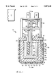
- FIG. 1 is a schematic, front sectional view of a semi-solid production apparatus according to the present invention.
- FIG. 2 is a schematic, side sectional view of the apparatus of FIG. 1.
- FIG. 3 is a schematic, side sectional view of the apparatus of FIG. 2 showing an alternate embodiment of the present invention.
- FIG. 4 is a schematic, side sectional view of the apparatus of FIG. 2 showing another alternate embodiment of the present invention.
- a semi-solid production apparatus is shown generally as reference numeral 10. Separated from the apparatus 10 is a source of molten material 11. Generally any material which may be processed into a semi-solid material 50 is suitable for use with this apparatus 10. Suitable molten materials 11 include pure metals such as aluminum or magnesium, metal alloys such as steel or aluminum alloy A356, and metal-ceramic particle mixtures such as aluminum and silicon carbide.
- the apparatus 10 includes a cylindrical chamber 12, a primary rotor 14, a secondary rotor 16, and a chamber cover 18.
- the chamber 12 has a inner bottom wall 20 and a cylindrical inner side wall 22 which are both preferably made of a refractory material.
- the chamber 12 has an outer support layer 24 preferably made of steel.
- the top of the chamber 12 is covered by a chamber cover 18.
- the chamber cover 18 similarly has a refractory material layer.
- Thermal control system 30 comprises heating segments 32 and cooling segments 34.
- the heating and cooling segments 32, 34 are mounted to, or embedded within, the outer layer 24 of the chamber 12.
- the heating and cooling segments 32, 34 may be oriented in many different ways, but as shown, the heating and cooling segments 32, 34 are interspersed around the circumference of the chamber 12.
- Heating and cooling segments 32, 34 are also mounted to the chamber cover 18. Individual heating and cooling segments 32, 34 may independently add and/or remove heat, thus enhancing the controllability of the temperature of the contents of the chamber 12.
- the primary rotor 14 has a rotor end 42 and a shaft 44 which extends upwards from the rotor end 42.
- the primary rotor shaft 44 extends through the chamber lid 18.
- the rotor end 42 is immersed in and entirely surrounded by the chamber 12.
- the rotor end 42 has L-shaped blades 43, preferably two such blades spaced 180 degrees apart, extending from the bottom of the rotor end 42.
- the L-shaped blades 43 have two portions, one of which is parallel to the inner side wall 22 and the other being parallel to the inner bottom wall 20.
- the L-shaped blades 43 when rotated, shear dendrites which tend to form on the inner side wall 22 and bottom wall 20 of the chamber 12.
- the rotation of the blades 43 promotes material mixing within horizontal planes.
- Other blade 43 geometries e.g. T-shaped
- the gap between the chamber bottom 20 and the blades 43 also should be less than two inches.
- a typical rotation speed of the shear rotor 14 is approximately 30 rpm.
- the secondary rotor 16 has a rotor end 48 and a shaft 46 extending from the rotor end 48.
- the shape of the rotor end 48 should be designed to encourage vertical mixing of the semi-solid material 50 and enhance the shearing of the semi-solid material 50.
- the rotor end 48 is preferably auger-shaped or screw-shaped, but many other shapes, such as blades tilted relative to a horizontal plane, will perform similarly.
- the shaft 46 extends upwardly from the auger-shaped rotor end 48.
- material in chamber 12 is forced to move in either an upwards or downwards direction.
- a typical rotation speed of the secondary rotor 16 is 300 rpm.
- the primary rotor 14 and the secondary rotor 16 are oriented relative to the chamber 12 and to each other so as to enhance both the shearing and three dimensional agitation of a semi-solid material 50.
- FIG. 1 it is seen that the primary rotor 14 revolves around the secondary rotor 16.
- the secondary rotor 16 rotates within the predominantly horizontal mixing action of the primary rotor 14. This configuration promotes thorough, three-dimensional mixing of the semi-solid material 50.
- FIG. 1 depicts a plurality of rotors, a single rotor that provides the appropriate shearing and mixing properties may be utilized. Such a single rotor must afford both shearing and mixing, the mixing being three-dimensional so that the semi-solid material 50 in the container 12 is maintainable at a substantially uniform temperature.
- the semi-solid material environment into which the rotors 14, 16 are immersed is quite harsh.
- the rotors 14, 16 are exposed to very high temperatures, often corrosive conditions, and considerable physical force.
- the preferred composition of the rotors 14, 16 is a heat and corrosion resistant alloy like stainless steel with a high-temperature MgZrO 3 ceramic coating.
- Other high-temperature resistant materials, such as a superalloy coated with Al 2 O 3 are also suitable.
- a frame 56 is mounted to the chamber lid 18.
- the frame 56 supports a primary drive motor 58 and a secondary drive motor 60.
- the respective motors 58, 60 are mechanically coupled to the shafts 44, 46 of the respective rotors 14, 16.
- the primary motor 58 is coupled to the primary rotor shaft 44 by a pair of reduction gears 62 and 64.
- the primary rotor shaft 44 is supported in the frame 56 by bearing sleeves 66.
- the secondary rotor shaft 46 is supported in frame 56 by bearing sleeve 68.
- Both motors 58, 60 may be connected to the rotors through reduction or step-up gearing to improve power and/or torque transmission.
- Electromagnetic stirring can effectuate the desired isothermal and three-dimensional shearing and mixing properties crucial to the present invention.
- Molten material 11 may be delivered to the chamber 12 in a number of different fashions.
- the molten material 11 is delivered through an orifice 70 in the chamber cover 18.
- the molten metal 11 may be delivered through an orifice in the side wall 22 (not shown) and/or through an orifice in the bottom wall 20 (also not shown).
- Semi-solid material 50 is formed from the molten material 11 upon agitation by the primary rotor 14 and the secondary rotor 16, and appropriate cooling from the thermal control system 30. After an initial start-up cycle, the process is semi-continuous whereby as semi-solid material 50 is removed from the chamber 12, molten material 11 is added. However, the rotors 14, 16 and the thermal control system 30 maintain the semi-solid 50 in a substantially isothermal state.
- the thermal control system 30 is also instrumental in starting up and shutting down the apparatus 10. During start-up, the thermal control system should bring the chamber 12 and its contents up to the appropriate temperature to receive molten material 11.
- the chamber 12 may have a large amount of solidified semi-solid material or solidified (previously molten) material remaining in it from a previous operation.
- the thermal control system 30 should be capable of delivering enough power to re-melt the solidified material.
- removal of semi-solid material 50 formed in the chamber 12 is preferably via a removal port 72 which extends through an orifice 71 in cover 18.
- One end of the removal port 72 must be below the surface of the semi-solid material 50.
- the removal port 72 is insulated and protects the semi-solid material 50 from being contaminated by the ambient atmosphere. Without such protection, oxidation would more readily occur on the outside of the semi-solid material and intersperse in any components made therefrom.
- a heater 80 Provided around the removal port 72 is a heater 80 to maintain the semi-solid material 50 at the desired temperature.
- the removal port 72 extends from the apparatus 10 through the chamber cover 18.
- the removal port 72 extends from the chamber side wall 22 which has an outlet orifice 112 as shown in FIG. 3.
- FIG. 3 also shows a removal port 73 extending from the bottom wall 20 which has an outlet orifice 113.
- the removal port includes a heater 80 to maintain the isothermal state of the semi-solid material 50 being removed.
- Effectuating semi-solid 50 flow through the port 72 may be achieved by any number of methods.
- a vacuum could be applied to the removal port 72, thus sucking the semi-solid out of the chamber 12.
- Gravity may be utilized as depicted in FIG. 3 at port 73.
- Other transfer methods utilizing mechanical means, such as submerged pistons, helical rotors, or other positive displacement actuators which produce a controlled rate of semi-solid material 50 transfer are also effective.
- a valve 83 is provided in the port 72.
- the valve 83 can be a simple gate valve or other liquid flow regulation device. It may be desirable to heat the valve 83 so that the semi-solid 50 is maintained at the desired temperature and clogging is prevented.
- Flow regulation may also be crudely effectuated by local solidification.
- a heater/cooler (not shown) can locally solidify the semi-solid 50 in port 72 thus stopping the flow. Later, the heater/cooler can reheat the material to resume the flow. This procedure would be part of a start-up and shut-down cycle, and is not necessarily part of the isothermal semi-solid material production process described above.
- FIG. 4 Another manner for transferring semi-solid material 50, while providing inherent flow control, utilizes a ladle 114 as depicted in FIG. 4.
- the ladle 114 removes semi-solid material 50 from the chamber 12 while a heater 82 which is mounted to the ladle 114 maintains the temperature of the semi-solid material 50 being removed.
- a ladle cup 115 of the ladle 114 is attached to a ladle actuator 116.
- the cup 115 is rotatable to pour out its contents, and the actuator 116 moves the ladle in the horizontal and vertical directions.
- semi-solid material 50 transfer may occur in successive cycles. During each cycle the above-described flow regulation allows a discrete amount of semi-solid material 50 to be removed. The amount of semi-solid material removed during each cycle should be small relative to the material remaining in the chamber 12. In this manner, the change in thermal mass within the chamber 12 during removal cycles is small. In a typical cycle, less than ten percent of the semi-solid 50 within chamber 12 is removed.
- Such a casting device includes that described in "Apparatus and Method for Integrated Semi-Solid Material Production and Casting" a provisional application filed Oct. 4, 1996, which is incorporated herein by reference.
- Other examples of appropriate casting devices include a mold, a forging die assembly as described in the specification of U.S. Pat. No. 5,287,719, or other commonly known die casting mechanisms.
- Oxides readily form on the outer layers of molten materials and semi-solid materials. Contaminants other than oxides also enter the molten and semi-solid material. In an inert environment, such as one of nitrogen or argon, oxide formation would be reduced or eliminated. The inert environment would also result in fewer contaminants in the semi-solid material. It may be more economical, however, to limit the controlled environment to discrete portions of the apparatus 10 such as the delivery of molten material 11 to the chamber 12. Another discrete and economical portion for environmental control may be the removal port 72 (or the ladle 114).
- the semi-solid material 50 no longer undergoes agitation and the material is soon to be cast into a component.
- any oxide skin that forms at this stage will not be dispersed throughout the material by mixing in the container 12. Instead, the oxides will be concentrated on the outer layers of the semi-solid. Therefore, to reduce both oxide formation and to reduce high-concentration oxide pockets, a controlled nitrogen environment (or other suitable and economical environment) would be advantageous at the removal port 72 stage.
- the rotors 14, 16 continuously mix the semi-solid aluminum keeping the temperature within the material substantially uniform.
- the solid particle size produced by this particular process is typically in the range of 50 to 200 microns and the percentage by volume of solids suspended in the semi-solid aluminum is approximately 20 percent.
- the semi-solid aluminum is transferred from the chamber 12 via removal port 72.
- the removal port heater 80 also maintains the semi-solid aluminum at 600 degrees Celsius.
- a component may be formed directly from the removed semi-solid aluminum, without any additional solidification or reheating steps.
Abstract
Description
Claims (15)
Priority Applications (9)
| Application Number | Priority Date | Filing Date | Title |
|---|---|---|---|
| US08/726,099 US5887640A (en) | 1996-10-04 | 1996-10-04 | Apparatus and method for semi-solid material production |
| BR9712257-2A BR9712257A (en) | 1996-10-04 | 1997-10-03 | Apparatus and method for the production of semi-solid material |
| AU46705/97A AU4670597A (en) | 1996-10-04 | 1997-10-03 | Apparatus and method for semi-solid material production |
| JP10516949A JP2001501538A (en) | 1996-10-04 | 1997-10-03 | Apparatus and method for producing semi-solid material |
| PCT/US1997/018016 WO1998014624A2 (en) | 1996-10-04 | 1997-10-03 | Apparatus and method for semi-solid material production |
| EP97945526A EP0946771A2 (en) | 1996-10-04 | 1997-10-03 | Apparatus and method for semi-solid material production |
| CA002268159A CA2268159A1 (en) | 1996-10-04 | 1997-10-03 | Apparatus and method for semi-solid material production |
| KR1019990702945A KR20000048914A (en) | 1996-10-04 | 1997-10-03 | Apparatus and method for semi-solid material production |
| US09/252,743 US6308768B1 (en) | 1996-10-04 | 1999-02-19 | Apparatus and method for semi-solid material production |
Applications Claiming Priority (1)
| Application Number | Priority Date | Filing Date | Title |
|---|---|---|---|
| US08/726,099 US5887640A (en) | 1996-10-04 | 1996-10-04 | Apparatus and method for semi-solid material production |
Related Child Applications (1)
| Application Number | Title | Priority Date | Filing Date |
|---|---|---|---|
| US09/252,743 Continuation US6308768B1 (en) | 1996-10-04 | 1999-02-19 | Apparatus and method for semi-solid material production |
Publications (1)
| Publication Number | Publication Date |
|---|---|
| US5887640A true US5887640A (en) | 1999-03-30 |
Family
ID=24917243
Family Applications (2)
| Application Number | Title | Priority Date | Filing Date |
|---|---|---|---|
| US08/726,099 Expired - Fee Related US5887640A (en) | 1996-10-04 | 1996-10-04 | Apparatus and method for semi-solid material production |
| US09/252,743 Expired - Fee Related US6308768B1 (en) | 1996-10-04 | 1999-02-19 | Apparatus and method for semi-solid material production |
Family Applications After (1)
| Application Number | Title | Priority Date | Filing Date |
|---|---|---|---|
| US09/252,743 Expired - Fee Related US6308768B1 (en) | 1996-10-04 | 1999-02-19 | Apparatus and method for semi-solid material production |
Country Status (8)
| Country | Link |
|---|---|
| US (2) | US5887640A (en) |
| EP (1) | EP0946771A2 (en) |
| JP (1) | JP2001501538A (en) |
| KR (1) | KR20000048914A (en) |
| AU (1) | AU4670597A (en) |
| BR (1) | BR9712257A (en) |
| CA (1) | CA2268159A1 (en) |
| WO (1) | WO1998014624A2 (en) |
Cited By (15)
| Publication number | Priority date | Publication date | Assignee | Title |
|---|---|---|---|---|
| US6443216B1 (en) | 2000-06-01 | 2002-09-03 | Aemp Corporation | Thermal jacket for a vessel |
| US6470955B1 (en) | 1998-07-24 | 2002-10-29 | Gibbs Die Casting Aluminum Co. | Semi-solid casting apparatus and method |
| US20030173052A1 (en) * | 2000-08-25 | 2003-09-18 | Murray Morris Taylor | Aluminium pressure casting |
| US6725901B1 (en) | 2002-12-27 | 2004-04-27 | Advanced Cardiovascular Systems, Inc. | Methods of manufacture of fully consolidated or porous medical devices |
| US20040173337A1 (en) * | 2003-03-04 | 2004-09-09 | Yurko James A. | Process and apparatus for preparing a metal alloy |
| US6796362B2 (en) | 2000-06-01 | 2004-09-28 | Brunswick Corporation | Apparatus for producing a metallic slurry material for use in semi-solid forming of shaped parts |
| US20040211542A1 (en) * | 2001-08-17 | 2004-10-28 | Winterbottom Walter L. | Apparatus for and method of producing slurry material without stirring for application in semi-solid forming |
| US20040261970A1 (en) * | 2003-06-27 | 2004-12-30 | Cyco Systems Corporation Pty Ltd. | Method and apparatus for producing components from metal and/or metal matrix composite materials |
| US20050087917A1 (en) * | 2000-06-01 | 2005-04-28 | Norville Samuel M. | Method and apparatus for containing and ejecting a thixotropic metal slurry |
| US20050151308A1 (en) * | 2000-06-01 | 2005-07-14 | Norville Samuel M. | Method and apparatus for making a thixotropic metal slurry |
| US20060038328A1 (en) * | 2000-06-01 | 2006-02-23 | Jian Lu | Method and apparatus for magnetically stirring a thixotropic metal slurry |
| US20070204968A1 (en) * | 2006-03-02 | 2007-09-06 | T.H.T. Presses, Inc. | Semi-solid molding method and apparatus |
| US20080308252A1 (en) * | 2007-06-15 | 2008-12-18 | Die Therm Engineering L.L.C. | Die casting control method |
| CN114939633A (en) * | 2022-04-13 | 2022-08-26 | 北京科技大学 | System and process for preparing and forming non-oxidation high-purity large-volume semi-solid slurry |
| USD978637S1 (en) | 2017-12-12 | 2023-02-21 | Rain Bird Corporation | Emitter part |
Families Citing this family (16)
| Publication number | Priority date | Publication date | Assignee | Title |
|---|---|---|---|---|
| GB2354471A (en) * | 1999-09-24 | 2001-03-28 | Univ Brunel | Producung semisolid metal slurries and shaped components therefrom |
| DE10212349C1 (en) * | 2002-03-13 | 2003-08-28 | Evgenij Sterling | Production of an alloy melt for casting comprises placing the melt having a temperature lying above the liquidus temperature of the alloy in a crystallization vessel, adding an alloy as a powder, and mixing the melt and powder |
| US7509993B1 (en) | 2005-08-13 | 2009-03-31 | Wisconsin Alumni Research Foundation | Semi-solid forming of metal-matrix nanocomposites |
| US7648085B2 (en) | 2006-02-22 | 2010-01-19 | Rain Bird Corporation | Drip emitter |
| CN102108455B (en) * | 2009-12-25 | 2013-11-06 | 清华大学 | Preparation method of aluminum-base composite material |
| CN102108450B (en) * | 2009-12-25 | 2012-08-29 | 清华大学 | Method for preparing magnesium-based composite material |
| US9877440B2 (en) | 2012-03-26 | 2018-01-30 | Rain Bird Corporation | Elastomeric emitter and methods relating to same |
| KR101507945B1 (en) * | 2012-12-26 | 2015-04-08 | 주식회사 포스코 | A method for manufacturing an alloy by a reaction in a molten metal container and a device for manufacturing an alloy |
| US10631473B2 (en) | 2013-08-12 | 2020-04-28 | Rain Bird Corporation | Elastomeric emitter and methods relating to same |
| CN103817309B (en) * | 2014-02-25 | 2016-05-04 | 张英华 | Casting of semi-molten equipment and technological process thereof |
| EP2957365B1 (en) * | 2014-06-20 | 2017-04-12 | Imr S.R.L. | Method for manufacturing a metallic object by casting |
| US10330559B2 (en) | 2014-09-11 | 2019-06-25 | Rain Bird Corporation | Methods and apparatus for checking emitter bonds in an irrigation drip line |
| CN105772654B (en) * | 2016-05-23 | 2018-11-06 | 浙江机电职业技术学院 | Mushy stage metal stirring mixing method |
| US10375904B2 (en) | 2016-07-18 | 2019-08-13 | Rain Bird Corporation | Emitter locating system and related methods |
| US11051466B2 (en) | 2017-01-27 | 2021-07-06 | Rain Bird Corporation | Pressure compensation members, emitters, drip line and methods relating to same |
| US10626998B2 (en) | 2017-05-15 | 2020-04-21 | Rain Bird Corporation | Drip emitter with check valve |
Citations (98)
| Publication number | Priority date | Publication date | Assignee | Title |
|---|---|---|---|---|
| US2745153A (en) * | 1955-02-02 | 1956-05-15 | Dow Chemical Co | Apparatus for dispensing shots of molten metal |
| US3157923A (en) * | 1960-09-08 | 1964-11-24 | Hodler Fritz | Apparatus for transporting molten metal |
| US3222776A (en) * | 1961-12-04 | 1965-12-14 | Ibm | Method and apparatus for treating molten material |
| US3528478A (en) * | 1968-07-25 | 1970-09-15 | Nat Lead Co | Method of die casting high melting point alloys |
| DE2320761A1 (en) * | 1973-04-25 | 1974-11-07 | Magnesium Ges Mbh | Cold chamber pressure die casting machine - with heater in pressure chamber to avoid metal residues |
| US3902544A (en) * | 1974-07-10 | 1975-09-02 | Massachusetts Inst Technology | Continuous process for forming an alloy containing non-dendritic primary solids |
| US3907192A (en) * | 1972-02-11 | 1975-09-23 | Glaverbel | Process for the manufacture of a glazing unit |
| US3920223A (en) * | 1973-07-05 | 1975-11-18 | Wallace F Krueger | Plural component mixing head |
| US3932980A (en) * | 1974-01-23 | 1976-01-20 | Takeda Chemical Industries, Ltd. | Apparatus for continuously making a mixture of viscous material with solid material |
| US3936298A (en) * | 1973-07-17 | 1976-02-03 | Massachusetts Institute Of Technology | Metal composition and methods for preparing liquid-solid alloy metal composition and for casting the metal compositions |
| US3948650A (en) * | 1972-05-31 | 1976-04-06 | Massachusetts Institute Of Technology | Composition and methods for preparing liquid-solid alloys for casting and casting methods employing the liquid-solid alloys |
| US3951651A (en) * | 1972-08-07 | 1976-04-20 | Massachusetts Institute Of Technology | Metal composition and methods for preparing liquid-solid alloy metal compositions and for casting the metal compositions |
| US3955802A (en) * | 1975-03-24 | 1976-05-11 | Bruyne Norman Adrian De | Orbital oscillating stirrer |
| US3979026A (en) * | 1974-09-16 | 1976-09-07 | Roger Howard Lee | Apparatus for dispensing particulate and viscous liquid material |
| US3993290A (en) * | 1975-10-16 | 1976-11-23 | Louis Kovich | Manually operated agitator for thixotropic suspensions |
| US4008883A (en) * | 1975-06-11 | 1977-02-22 | Robert Frutos Zubieta | Blender |
| US4049204A (en) * | 1976-09-23 | 1977-09-20 | Mckee Bros. Limited | Fan for forage harvesting system |
| US4065105A (en) * | 1976-09-17 | 1977-12-27 | Amax Inc. | Fluidizing means for reducing viscosity of slurries |
| US4072543A (en) * | 1977-01-24 | 1978-02-07 | Amax Inc. | Dual-phase hot-rolled steel strip |
| US4089680A (en) * | 1976-09-22 | 1978-05-16 | Massachusetts Institute Of Technology | Method and apparatus for forming ferrous liquid-solid metal compositions |
| US4116423A (en) * | 1977-05-23 | 1978-09-26 | Rheocast Corporation | Apparatus and method to form metal containing nondendritic primary solids |
| US4124307A (en) * | 1976-07-17 | 1978-11-07 | Fried. Krupp Gmbh | Homogenizer for viscous materials |
| US4194552A (en) * | 1977-05-23 | 1980-03-25 | Rheocast Corporation | Method to form metal containing nondendritic primary solids |
| SU732073A1 (en) * | 1978-06-20 | 1980-05-05 | Предприятие П/Я Р-6668 | Apparatus for preparing and dispensing partly solidified melts |
| US4215628A (en) * | 1978-08-18 | 1980-08-05 | Dodd William A Jr | Infusion and stirring device |
| US4229210A (en) * | 1977-12-12 | 1980-10-21 | Olin Corporation | Method for the preparation of thixotropic slurries |
| US4231664A (en) * | 1979-03-21 | 1980-11-04 | Dependable-Fordath, Inc. | Method and apparatus for combining high speed horizontal and high speed vertical continuous mixing of chemically bonded foundry sand |
| US4278355A (en) * | 1978-07-25 | 1981-07-14 | Forberg Halvor Gudmund | Method of mixing particulate components |
| US4305673A (en) * | 1980-03-25 | 1981-12-15 | General Signal Corporation | High efficiency mixing impeller |
| US4310352A (en) * | 1979-06-20 | 1982-01-12 | Centro Ricerche Fiat S.P.A. | Process for the preparation of a mixture comprising a solid phase and a liquid phase of a metal alloy, and device for its performance |
| US4310124A (en) * | 1978-12-05 | 1982-01-12 | Friedrich Wilh. Schwing Gmbh | Mixer for viscous materials, for example for filter cake, pulp or the like |
| US4345637A (en) * | 1977-11-21 | 1982-08-24 | Massachusetts Institute Of Technology | Method for forming high fraction solid compositions by die casting |
| US4347889A (en) * | 1979-01-09 | 1982-09-07 | Nissan Motor Co., Ltd. | Diecasting apparatus |
| US4361404A (en) * | 1981-04-06 | 1982-11-30 | Pettibone Corporation | Mixing equipment and agitator therefor for use with granular material and method of producing prepared granular material |
| US4373950A (en) * | 1979-10-09 | 1983-02-15 | Showa Aluminium Kabushiki Kaisha | Process of preparing aluminum of high purity |
| US4382685A (en) * | 1979-07-17 | 1983-05-10 | Techne (Cambridge) Limited | Method and apparatus for stirring particles in suspension such as microcarriers for anchorage-dependent living cells in a liquid culture medium |
| US4390285A (en) * | 1980-08-24 | 1983-06-28 | Draiswerke Gmbh | Method and apparatus for mixing solids with liquids, in particular for gluing wood chips |
| US4397687A (en) * | 1982-05-21 | 1983-08-09 | Massachusetts Institute Of Technology | Mixing device and method for mixing molten metals |
| US4434837A (en) * | 1979-02-26 | 1984-03-06 | International Telephone And Telegraph Corporation | Process and apparatus for making thixotropic metal slurries |
| US4436429A (en) * | 1981-05-11 | 1984-03-13 | William A. Strong | Slurry production system |
| US4453829A (en) * | 1982-09-29 | 1984-06-12 | The Dow Chemical Company | Apparatus for mixing solids and fluids |
| US4469444A (en) * | 1982-07-21 | 1984-09-04 | Micafil Ag | Mixing and degassing apparatus for viscous substances |
| US4482012A (en) * | 1982-06-01 | 1984-11-13 | International Telephone And Telegraph Corporation | Process and apparatus for continuous slurry casting |
| US4506982A (en) * | 1981-08-03 | 1985-03-26 | Union Oil Company Of California | Apparatus for continuously blending viscous liquids with particulate solids |
| US4534657A (en) * | 1983-07-14 | 1985-08-13 | Crepaco, Inc. | Blending and emulsifying apparatus |
| US4565241A (en) * | 1982-06-01 | 1986-01-21 | International Telephone And Telegraph Corporation | Process for preparing a slurry structured metal composition |
| US4565242A (en) * | 1981-03-13 | 1986-01-21 | Kubota Ltd. | Heat accumulating material enclosing container and heat accumulating apparatus |
| US4580616A (en) * | 1982-12-06 | 1986-04-08 | Techmet Corporation | Method and apparatus for controlled solidification of metals |
| US4620795A (en) * | 1983-01-12 | 1986-11-04 | The United States Of America As Represented By The United States Department Of Energy | Fluidizing device for solid particulates |
| US4635706A (en) * | 1985-06-06 | 1987-01-13 | The Dow Chemical Company | Molten metal handling system |
| JPS6250065A (en) * | 1985-08-30 | 1987-03-04 | Nippon Kokan Kk <Nkk> | Welding method for thick-walled steel plate |
| US4687042A (en) * | 1986-07-23 | 1987-08-18 | Alumax, Inc. | Method of producing shaped metal parts |
| US4694882A (en) * | 1981-12-01 | 1987-09-22 | The Dow Chemical Company | Method for making thixotropic materials |
| US4694881A (en) * | 1981-12-01 | 1987-09-22 | The Dow Chemical Company | Method for making thixotropic materials |
| WO1987006624A1 (en) * | 1986-05-01 | 1987-11-05 | Dural Aluminum Composites Corporation | Cast reinforced composite material |
| US4709746A (en) * | 1982-06-01 | 1987-12-01 | Alumax, Inc. | Process and apparatus for continuous slurry casting |
| JPS63199016A (en) * | 1987-02-12 | 1988-08-17 | Ishikawajima Harima Heavy Ind Co Ltd | Continuous extruding apparatus |
| US4771818A (en) * | 1979-12-14 | 1988-09-20 | Alumax Inc. | Process of shaping a metal alloy product |
| US4775239A (en) * | 1985-12-11 | 1988-10-04 | Bhs-Bayerische Berg-, Hutten- Und Salzwerke Ag | Double shaft forced-feed mixer for continuous and discontinuous manner of operation |
| US4799862A (en) * | 1986-07-18 | 1989-01-24 | National Research Development Corporation | Impellers |
| US4799801A (en) * | 1987-03-18 | 1989-01-24 | Alfred Fischbach Kg Kunststoff-Spritzgubwerk | Mixing device for pasty multicomponent materials |
| US4804034A (en) * | 1985-03-25 | 1989-02-14 | Osprey Metals Limited | Method of manufacture of a thixotropic deposit |
| US4865808A (en) * | 1987-03-30 | 1989-09-12 | Agency Of Industrial Science And Technology | Method for making hypereutetic Al-Si alloy composite materials |
| US4874471A (en) * | 1986-11-26 | 1989-10-17 | Centre De Recherches Metallurgiques-Centrum Voor Research In De Metallurgie | Device for casting a metal in the pasty phase |
| JPH01313164A (en) * | 1988-06-14 | 1989-12-18 | Nkk Corp | Casting method for semimolten metal |
| JPH01313141A (en) * | 1988-06-14 | 1989-12-18 | Nkk Corp | Method for casting semi-molten metal |
| US4893941A (en) * | 1987-07-06 | 1990-01-16 | Wayte Joseph M | Apparatus for mixing viscous liquid in a container |
| US4926924A (en) * | 1985-03-25 | 1990-05-22 | Osprey Metals Ltd. | Deposition method including recycled solid particles |
| US4958678A (en) * | 1987-12-27 | 1990-09-25 | Yugenkaisha Idearesearch | Method for producing reinforced block material of metal or the like |
| US4964455A (en) * | 1988-07-07 | 1990-10-23 | Aluminum Pechiney | Method of making thixotropic metal products by continuous casting |
| US5009844A (en) * | 1989-12-01 | 1991-04-23 | General Motors Corporation | Process for manufacturing spheroidal hypoeutectic aluminum alloy |
| US5037209A (en) * | 1988-02-08 | 1991-08-06 | Wyss Kurt W | Apparatus for the mixing of fluids, in particular pasty media and a process for its operation |
| US5085512A (en) * | 1988-05-16 | 1992-02-04 | Michael Doman | Apparatus for the moving of liquid, pasty and/or pourable media |
| EP0476843A1 (en) * | 1990-09-11 | 1992-03-25 | Rheo-Technology, Ltd | Process for the production of semi-solidified metal composition |
| US5110547A (en) * | 1990-10-29 | 1992-05-05 | Rheo-Technology, Ltd. | Process and apparatus for the production of semi-solidified metal composition |
| US5121329A (en) * | 1989-10-30 | 1992-06-09 | Stratasys, Inc. | Apparatus and method for creating three-dimensional objects |
| US5135564A (en) * | 1990-12-28 | 1992-08-04 | Rheo-Technology, Ltd. | Method and apparatus for the production of semi-solidified metal composition |
| US5161888A (en) * | 1991-09-26 | 1992-11-10 | Wenger Manufacturing, Inc. | Dual shaft preconditioning device having differentiated conditioning zones for farinaceous materials |
| US5161601A (en) * | 1990-04-12 | 1992-11-10 | Stampal, S.P.A. | Process and relevant apparatus for the indirect casting of billets with metal alloy in semi-liquid or paste-like state |
| US5178204A (en) * | 1990-12-10 | 1993-01-12 | Kelly James E | Method and apparatus for rheocasting |
| US5186236A (en) * | 1990-12-21 | 1993-02-16 | Alusuisse-Lonza Services Ltd. | Process for producing a liquid-solid metal alloy phase for further processing as material in the thixotropic state |
| US5219018A (en) * | 1990-01-04 | 1993-06-15 | Aluminium Pechiney | Method of producing thixotropic metallic products by continuous casting, with polyphase current electromagnetic agitation |
| US5257657A (en) * | 1990-07-11 | 1993-11-02 | Incre, Inc. | Method for producing a free-form solid-phase object from a material in the liquid phase |
| US5287719A (en) * | 1991-08-22 | 1994-02-22 | Rheo-Technology, Ltd. | Method of forming semi-solidified metal composition |
| US5313815A (en) * | 1992-11-03 | 1994-05-24 | Amax, Inc. | Apparatus and method for producing shaped metal parts using continuous heating |
| US5342124A (en) * | 1993-02-12 | 1994-08-30 | Cmi Corporation | Mixer having blades arranged in a discontinuous helical pattern |
| US5343926A (en) * | 1991-01-02 | 1994-09-06 | Olin Corporation | Metal spray forming using multiple nozzles |
| US5375645A (en) * | 1990-11-30 | 1994-12-27 | Micromatic Operations, Inc. | Apparatus and process for producing shaped articles from semisolid metal preforms |
| US5381847A (en) * | 1993-06-10 | 1995-01-17 | Olin Corporation | Vertical casting process |
| US5411330A (en) * | 1992-04-28 | 1995-05-02 | Novecon Technologies, L.P. | Moebius shaped mixing accessory |
| EP0657235A1 (en) * | 1993-12-08 | 1995-06-14 | Rheo-Technology, Ltd | Process for the production of semi-solidified metal composition |
| US5464053A (en) * | 1992-09-29 | 1995-11-07 | Weber S.R.L. | Process for producing rheocast ingots, particularly from which to produce high-mechanical-performance die castings |
| WO1995034393A1 (en) * | 1994-06-14 | 1995-12-21 | Cornell Research Foundation, Inc. | Method and apparatus for injection molding of semi-solid metals |
| US5478148A (en) * | 1993-11-18 | 1995-12-26 | Seva | Oscillating stirring apparatus for mixing viscous products and or fluids |
| EP0719606A1 (en) * | 1994-12-28 | 1996-07-03 | Ahresty Corporation | A Method of manufacturing metallic slurry for casting |
| EP0761344A2 (en) * | 1995-09-01 | 1997-03-12 | Takata Corporation | Method and apparatus for manufacturing light metal alloy |
| EP0765945A1 (en) * | 1995-06-06 | 1997-04-02 | Reynolds Metals Company | Method of forming semi-solid metal and products made thereby |
| WO1997012709A1 (en) * | 1995-10-05 | 1997-04-10 | Reynolds Wheels S.P.A | A method and device for the thixotropic casting of metal alloy products |
Family Cites Families (3)
| Publication number | Priority date | Publication date | Assignee | Title |
|---|---|---|---|---|
| JPH01178345A (en) * | 1988-01-09 | 1989-07-14 | Ishikawajima Harima Heavy Ind Co Ltd | Apparatus for quantitatively dividing semi-solidified metal slurry |
| JPH01306047A (en) * | 1988-05-31 | 1989-12-11 | Nkk Corp | Production of semi-molten metal |
| US5388633A (en) * | 1992-02-13 | 1995-02-14 | The Dow Chemical Company | Method and apparatus for charging metal to a die cast |
-
1996
- 1996-10-04 US US08/726,099 patent/US5887640A/en not_active Expired - Fee Related
-
1997
- 1997-10-03 WO PCT/US1997/018016 patent/WO1998014624A2/en not_active Application Discontinuation
- 1997-10-03 KR KR1019990702945A patent/KR20000048914A/en not_active Application Discontinuation
- 1997-10-03 BR BR9712257-2A patent/BR9712257A/en not_active IP Right Cessation
- 1997-10-03 CA CA002268159A patent/CA2268159A1/en not_active Abandoned
- 1997-10-03 JP JP10516949A patent/JP2001501538A/en active Pending
- 1997-10-03 AU AU46705/97A patent/AU4670597A/en not_active Abandoned
- 1997-10-03 EP EP97945526A patent/EP0946771A2/en not_active Ceased
-
1999
- 1999-02-19 US US09/252,743 patent/US6308768B1/en not_active Expired - Fee Related
Patent Citations (100)
| Publication number | Priority date | Publication date | Assignee | Title |
|---|---|---|---|---|
| US2745153A (en) * | 1955-02-02 | 1956-05-15 | Dow Chemical Co | Apparatus for dispensing shots of molten metal |
| US3157923A (en) * | 1960-09-08 | 1964-11-24 | Hodler Fritz | Apparatus for transporting molten metal |
| US3222776A (en) * | 1961-12-04 | 1965-12-14 | Ibm | Method and apparatus for treating molten material |
| US3528478A (en) * | 1968-07-25 | 1970-09-15 | Nat Lead Co | Method of die casting high melting point alloys |
| US3907192A (en) * | 1972-02-11 | 1975-09-23 | Glaverbel | Process for the manufacture of a glazing unit |
| US3948650A (en) * | 1972-05-31 | 1976-04-06 | Massachusetts Institute Of Technology | Composition and methods for preparing liquid-solid alloys for casting and casting methods employing the liquid-solid alloys |
| US3951651A (en) * | 1972-08-07 | 1976-04-20 | Massachusetts Institute Of Technology | Metal composition and methods for preparing liquid-solid alloy metal compositions and for casting the metal compositions |
| DE2320761A1 (en) * | 1973-04-25 | 1974-11-07 | Magnesium Ges Mbh | Cold chamber pressure die casting machine - with heater in pressure chamber to avoid metal residues |
| US3920223A (en) * | 1973-07-05 | 1975-11-18 | Wallace F Krueger | Plural component mixing head |
| US3936298A (en) * | 1973-07-17 | 1976-02-03 | Massachusetts Institute Of Technology | Metal composition and methods for preparing liquid-solid alloy metal composition and for casting the metal compositions |
| US3932980A (en) * | 1974-01-23 | 1976-01-20 | Takeda Chemical Industries, Ltd. | Apparatus for continuously making a mixture of viscous material with solid material |
| US3902544A (en) * | 1974-07-10 | 1975-09-02 | Massachusetts Inst Technology | Continuous process for forming an alloy containing non-dendritic primary solids |
| US3979026A (en) * | 1974-09-16 | 1976-09-07 | Roger Howard Lee | Apparatus for dispensing particulate and viscous liquid material |
| US3955802A (en) * | 1975-03-24 | 1976-05-11 | Bruyne Norman Adrian De | Orbital oscillating stirrer |
| US4008883A (en) * | 1975-06-11 | 1977-02-22 | Robert Frutos Zubieta | Blender |
| US3993290A (en) * | 1975-10-16 | 1976-11-23 | Louis Kovich | Manually operated agitator for thixotropic suspensions |
| US4124307A (en) * | 1976-07-17 | 1978-11-07 | Fried. Krupp Gmbh | Homogenizer for viscous materials |
| US4065105A (en) * | 1976-09-17 | 1977-12-27 | Amax Inc. | Fluidizing means for reducing viscosity of slurries |
| US4108643A (en) * | 1976-09-22 | 1978-08-22 | Massachusetts Institute Of Technology | Method for forming high fraction solid metal compositions and composition therefor |
| US4089680A (en) * | 1976-09-22 | 1978-05-16 | Massachusetts Institute Of Technology | Method and apparatus for forming ferrous liquid-solid metal compositions |
| US4049204A (en) * | 1976-09-23 | 1977-09-20 | Mckee Bros. Limited | Fan for forage harvesting system |
| US4072543A (en) * | 1977-01-24 | 1978-02-07 | Amax Inc. | Dual-phase hot-rolled steel strip |
| US4116423A (en) * | 1977-05-23 | 1978-09-26 | Rheocast Corporation | Apparatus and method to form metal containing nondendritic primary solids |
| US4194552A (en) * | 1977-05-23 | 1980-03-25 | Rheocast Corporation | Method to form metal containing nondendritic primary solids |
| US4345637A (en) * | 1977-11-21 | 1982-08-24 | Massachusetts Institute Of Technology | Method for forming high fraction solid compositions by die casting |
| US4229210A (en) * | 1977-12-12 | 1980-10-21 | Olin Corporation | Method for the preparation of thixotropic slurries |
| SU732073A1 (en) * | 1978-06-20 | 1980-05-05 | Предприятие П/Я Р-6668 | Apparatus for preparing and dispensing partly solidified melts |
| US4278355A (en) * | 1978-07-25 | 1981-07-14 | Forberg Halvor Gudmund | Method of mixing particulate components |
| US4215628A (en) * | 1978-08-18 | 1980-08-05 | Dodd William A Jr | Infusion and stirring device |
| US4310124A (en) * | 1978-12-05 | 1982-01-12 | Friedrich Wilh. Schwing Gmbh | Mixer for viscous materials, for example for filter cake, pulp or the like |
| US4347889A (en) * | 1979-01-09 | 1982-09-07 | Nissan Motor Co., Ltd. | Diecasting apparatus |
| US4434837A (en) * | 1979-02-26 | 1984-03-06 | International Telephone And Telegraph Corporation | Process and apparatus for making thixotropic metal slurries |
| US4231664A (en) * | 1979-03-21 | 1980-11-04 | Dependable-Fordath, Inc. | Method and apparatus for combining high speed horizontal and high speed vertical continuous mixing of chemically bonded foundry sand |
| US4310352A (en) * | 1979-06-20 | 1982-01-12 | Centro Ricerche Fiat S.P.A. | Process for the preparation of a mixture comprising a solid phase and a liquid phase of a metal alloy, and device for its performance |
| US4382685A (en) * | 1979-07-17 | 1983-05-10 | Techne (Cambridge) Limited | Method and apparatus for stirring particles in suspension such as microcarriers for anchorage-dependent living cells in a liquid culture medium |
| US4373950A (en) * | 1979-10-09 | 1983-02-15 | Showa Aluminium Kabushiki Kaisha | Process of preparing aluminum of high purity |
| US4771818A (en) * | 1979-12-14 | 1988-09-20 | Alumax Inc. | Process of shaping a metal alloy product |
| US4305673A (en) * | 1980-03-25 | 1981-12-15 | General Signal Corporation | High efficiency mixing impeller |
| US4390285A (en) * | 1980-08-24 | 1983-06-28 | Draiswerke Gmbh | Method and apparatus for mixing solids with liquids, in particular for gluing wood chips |
| US4565242A (en) * | 1981-03-13 | 1986-01-21 | Kubota Ltd. | Heat accumulating material enclosing container and heat accumulating apparatus |
| US4361404A (en) * | 1981-04-06 | 1982-11-30 | Pettibone Corporation | Mixing equipment and agitator therefor for use with granular material and method of producing prepared granular material |
| US4436429A (en) * | 1981-05-11 | 1984-03-13 | William A. Strong | Slurry production system |
| US4506982A (en) * | 1981-08-03 | 1985-03-26 | Union Oil Company Of California | Apparatus for continuously blending viscous liquids with particulate solids |
| US4694881A (en) * | 1981-12-01 | 1987-09-22 | The Dow Chemical Company | Method for making thixotropic materials |
| US4694882A (en) * | 1981-12-01 | 1987-09-22 | The Dow Chemical Company | Method for making thixotropic materials |
| US4397687A (en) * | 1982-05-21 | 1983-08-09 | Massachusetts Institute Of Technology | Mixing device and method for mixing molten metals |
| US4482012A (en) * | 1982-06-01 | 1984-11-13 | International Telephone And Telegraph Corporation | Process and apparatus for continuous slurry casting |
| US4565241A (en) * | 1982-06-01 | 1986-01-21 | International Telephone And Telegraph Corporation | Process for preparing a slurry structured metal composition |
| US4709746A (en) * | 1982-06-01 | 1987-12-01 | Alumax, Inc. | Process and apparatus for continuous slurry casting |
| US4469444A (en) * | 1982-07-21 | 1984-09-04 | Micafil Ag | Mixing and degassing apparatus for viscous substances |
| US4453829A (en) * | 1982-09-29 | 1984-06-12 | The Dow Chemical Company | Apparatus for mixing solids and fluids |
| US4580616A (en) * | 1982-12-06 | 1986-04-08 | Techmet Corporation | Method and apparatus for controlled solidification of metals |
| US4620795A (en) * | 1983-01-12 | 1986-11-04 | The United States Of America As Represented By The United States Department Of Energy | Fluidizing device for solid particulates |
| US4534657A (en) * | 1983-07-14 | 1985-08-13 | Crepaco, Inc. | Blending and emulsifying apparatus |
| US4926924A (en) * | 1985-03-25 | 1990-05-22 | Osprey Metals Ltd. | Deposition method including recycled solid particles |
| US4804034A (en) * | 1985-03-25 | 1989-02-14 | Osprey Metals Limited | Method of manufacture of a thixotropic deposit |
| US4635706A (en) * | 1985-06-06 | 1987-01-13 | The Dow Chemical Company | Molten metal handling system |
| JPS6250065A (en) * | 1985-08-30 | 1987-03-04 | Nippon Kokan Kk <Nkk> | Welding method for thick-walled steel plate |
| US4775239A (en) * | 1985-12-11 | 1988-10-04 | Bhs-Bayerische Berg-, Hutten- Und Salzwerke Ag | Double shaft forced-feed mixer for continuous and discontinuous manner of operation |
| WO1987006624A1 (en) * | 1986-05-01 | 1987-11-05 | Dural Aluminum Composites Corporation | Cast reinforced composite material |
| US4799862A (en) * | 1986-07-18 | 1989-01-24 | National Research Development Corporation | Impellers |
| US4687042A (en) * | 1986-07-23 | 1987-08-18 | Alumax, Inc. | Method of producing shaped metal parts |
| US4874471A (en) * | 1986-11-26 | 1989-10-17 | Centre De Recherches Metallurgiques-Centrum Voor Research In De Metallurgie | Device for casting a metal in the pasty phase |
| JPS63199016A (en) * | 1987-02-12 | 1988-08-17 | Ishikawajima Harima Heavy Ind Co Ltd | Continuous extruding apparatus |
| US4799801A (en) * | 1987-03-18 | 1989-01-24 | Alfred Fischbach Kg Kunststoff-Spritzgubwerk | Mixing device for pasty multicomponent materials |
| US4865808A (en) * | 1987-03-30 | 1989-09-12 | Agency Of Industrial Science And Technology | Method for making hypereutetic Al-Si alloy composite materials |
| US4893941A (en) * | 1987-07-06 | 1990-01-16 | Wayte Joseph M | Apparatus for mixing viscous liquid in a container |
| US4958678A (en) * | 1987-12-27 | 1990-09-25 | Yugenkaisha Idearesearch | Method for producing reinforced block material of metal or the like |
| US5037209A (en) * | 1988-02-08 | 1991-08-06 | Wyss Kurt W | Apparatus for the mixing of fluids, in particular pasty media and a process for its operation |
| US5085512A (en) * | 1988-05-16 | 1992-02-04 | Michael Doman | Apparatus for the moving of liquid, pasty and/or pourable media |
| JPH01313164A (en) * | 1988-06-14 | 1989-12-18 | Nkk Corp | Casting method for semimolten metal |
| JPH01313141A (en) * | 1988-06-14 | 1989-12-18 | Nkk Corp | Method for casting semi-molten metal |
| US4964455A (en) * | 1988-07-07 | 1990-10-23 | Aluminum Pechiney | Method of making thixotropic metal products by continuous casting |
| US5121329A (en) * | 1989-10-30 | 1992-06-09 | Stratasys, Inc. | Apparatus and method for creating three-dimensional objects |
| US5009844A (en) * | 1989-12-01 | 1991-04-23 | General Motors Corporation | Process for manufacturing spheroidal hypoeutectic aluminum alloy |
| US5219018A (en) * | 1990-01-04 | 1993-06-15 | Aluminium Pechiney | Method of producing thixotropic metallic products by continuous casting, with polyphase current electromagnetic agitation |
| US5161601A (en) * | 1990-04-12 | 1992-11-10 | Stampal, S.P.A. | Process and relevant apparatus for the indirect casting of billets with metal alloy in semi-liquid or paste-like state |
| US5257657A (en) * | 1990-07-11 | 1993-11-02 | Incre, Inc. | Method for producing a free-form solid-phase object from a material in the liquid phase |
| EP0476843A1 (en) * | 1990-09-11 | 1992-03-25 | Rheo-Technology, Ltd | Process for the production of semi-solidified metal composition |
| US5144998A (en) * | 1990-09-11 | 1992-09-08 | Rheo-Technology Ltd. | Process for the production of semi-solidified metal composition |
| US5110547A (en) * | 1990-10-29 | 1992-05-05 | Rheo-Technology, Ltd. | Process and apparatus for the production of semi-solidified metal composition |
| US5375645A (en) * | 1990-11-30 | 1994-12-27 | Micromatic Operations, Inc. | Apparatus and process for producing shaped articles from semisolid metal preforms |
| US5178204A (en) * | 1990-12-10 | 1993-01-12 | Kelly James E | Method and apparatus for rheocasting |
| US5186236A (en) * | 1990-12-21 | 1993-02-16 | Alusuisse-Lonza Services Ltd. | Process for producing a liquid-solid metal alloy phase for further processing as material in the thixotropic state |
| US5135564A (en) * | 1990-12-28 | 1992-08-04 | Rheo-Technology, Ltd. | Method and apparatus for the production of semi-solidified metal composition |
| US5343926A (en) * | 1991-01-02 | 1994-09-06 | Olin Corporation | Metal spray forming using multiple nozzles |
| US5287719A (en) * | 1991-08-22 | 1994-02-22 | Rheo-Technology, Ltd. | Method of forming semi-solidified metal composition |
| US5161888A (en) * | 1991-09-26 | 1992-11-10 | Wenger Manufacturing, Inc. | Dual shaft preconditioning device having differentiated conditioning zones for farinaceous materials |
| US5411330A (en) * | 1992-04-28 | 1995-05-02 | Novecon Technologies, L.P. | Moebius shaped mixing accessory |
| US5464053A (en) * | 1992-09-29 | 1995-11-07 | Weber S.R.L. | Process for producing rheocast ingots, particularly from which to produce high-mechanical-performance die castings |
| US5313815A (en) * | 1992-11-03 | 1994-05-24 | Amax, Inc. | Apparatus and method for producing shaped metal parts using continuous heating |
| US5342124A (en) * | 1993-02-12 | 1994-08-30 | Cmi Corporation | Mixer having blades arranged in a discontinuous helical pattern |
| US5381847A (en) * | 1993-06-10 | 1995-01-17 | Olin Corporation | Vertical casting process |
| US5478148A (en) * | 1993-11-18 | 1995-12-26 | Seva | Oscillating stirring apparatus for mixing viscous products and or fluids |
| EP0657235A1 (en) * | 1993-12-08 | 1995-06-14 | Rheo-Technology, Ltd | Process for the production of semi-solidified metal composition |
| WO1995034393A1 (en) * | 1994-06-14 | 1995-12-21 | Cornell Research Foundation, Inc. | Method and apparatus for injection molding of semi-solid metals |
| EP0719606A1 (en) * | 1994-12-28 | 1996-07-03 | Ahresty Corporation | A Method of manufacturing metallic slurry for casting |
| EP0765945A1 (en) * | 1995-06-06 | 1997-04-02 | Reynolds Metals Company | Method of forming semi-solid metal and products made thereby |
| EP0761344A2 (en) * | 1995-09-01 | 1997-03-12 | Takata Corporation | Method and apparatus for manufacturing light metal alloy |
| WO1997012709A1 (en) * | 1995-10-05 | 1997-04-10 | Reynolds Wheels S.P.A | A method and device for the thixotropic casting of metal alloy products |
Non-Patent Citations (22)
| Title |
|---|
| "A World Wide Assessment of Rapid Prototyping Technologies," RF Aubin United Technologies Research Center Report No. 94-13, dated Jan. 1994, 29 pages. |
| "Structure and Properties of Thiocast Steels" by K.P. Young, et al., Metals Technology, Apr. 1979. |
| A World Wide Assessment of Rapid Prototyping Technologies, RF Aubin United Technologies Research Center Report No. 94 13, dated Jan. 1994, 29 pages. * |
| H. L. Marcus and D. L. Bourell, "Solid Freeform Fabrication," Advanced Materials & Processes, dated Sep. 1993, pp. 28-31 and 34-35. |
| H. L. Marcus and D. L. Bourell, Solid Freeform Fabrication, Advanced Materials & Processes, dated Sep. 1993, pp. 28 31 and 34 35. * |
| J. W. Comb and W. R. Priedeman, Stratasys, Inc., "Control Parameters and Materials Criteria for Rapid Prototyping Systems," copyright date 1993, pp. 86-93. |
| J. W. Comb and W. R. Priedeman, Stratasys, Inc., Control Parameters and Materials Criteria for Rapid Prototyping Systems, copyright date 1993, pp. 86 93. * |
| J. W. Comb, W. R. Priedeman and P. W. Turley, Stratasys, Inc., "Control Parameters and Material Selection Criteria for Fused Deposition Modeling," undated, pp. 163-170. |
| J. W. Comb, W. R. Priedeman and P. W. Turley, Stratasys, Inc., Control Parameters and Material Selection Criteria for Fused Deposition Modeling, undated, pp. 163 170. * |
| M. C. Flemings and K. P. Young, 9th SDCE International Die Casting Exposition and Congress, Jun. 6 9, 1977, Thixocasting of Steel, Paper No. G T77 092, dated Jun. 6 9, 1977, 8 pages. * |
| M. C. Flemings and K. P. Young, 9th SDCE International Die Casting Exposition and Congress, Jun. 6-9, 1977, "Thixocasting of Steel," Paper No. G-T77-092, dated Jun. 6-9, 1977, 8 pages. |
| M. E. Orme, K. Willis and J. Courter, Department of Mechanical and Aerospace Engineering, University of California Irvine, The Development of Rapid Prototyping of Metallic Components Via Ulta Uniform Droplet Deposition, undated, pp. 27 36. * |
| M. E. Orme, K. Willis and J. Courter, Department of Mechanical and Aerospace Engineering, University of California-Irvine, "The Development of Rapid Prototyping of Metallic Components Via Ulta-Uniform Droplet Deposition," undated, pp. 27-36. |
| R. E. Reed Hill and R. Abbashian, Physical Metallurgy Principles, PWS Kent Publishing Company, 1992, pp. 325 349. * |
| R. E. Reed-Hill and R. Abbashian, Physical Metallurgy Principles, PWS-Kent Publishing Company, 1992, pp. 325-349. |
| S. B. Brown and M. C. Flemings, "Net-Shape Forming Via Semi-Solid Processing," Advanced Materials & Processes, dated Jan. 1993, pp. 36-40. |
| S. B. Brown and M. C. Flemings, Net Shape Forming Via Semi Solid Processing, Advanced Materials & Processes, dated Jan. 1993, pp. 36 40. * |
| Stratasys, Inc., "Rapid Prototyping Using FDM: A Fast, Precise, Safe Technology," paper from the Solid Freeform Fabrication Symposium, Aug. 3-5, 1992, pp. 301-308. |
| Stratasys, Inc., Rapid Prototyping Using FDM: A Fast, Precise, Safe Technology, paper from the Solid Freeform Fabrication Symposium, Aug. 3 5, 1992, pp. 301 308. * |
| Structure and Properties of Thiocast Steels by K.P. Young, et al., Metals Technology, Apr. 1979. * |
| Thesis: "The Machine Casting of High Temperature Semi-Solid Materials", By Danial G. Backman, Massachussetts Institute of Technology, Sep., 1975. |
| Thesis: The Machine Casting of High Temperature Semi Solid Materials , By Danial G. Backman, Massachussetts Institute of Technology, Sep., 1975. * |
Cited By (22)
| Publication number | Priority date | Publication date | Assignee | Title |
|---|---|---|---|---|
| US6470955B1 (en) | 1998-07-24 | 2002-10-29 | Gibbs Die Casting Aluminum Co. | Semi-solid casting apparatus and method |
| US6640879B2 (en) | 1998-07-24 | 2003-11-04 | Gibbs Die Casting Aluminum Co. | Semi-solid casting apparatus and method |
| US20050151308A1 (en) * | 2000-06-01 | 2005-07-14 | Norville Samuel M. | Method and apparatus for making a thixotropic metal slurry |
| US6443216B1 (en) | 2000-06-01 | 2002-09-03 | Aemp Corporation | Thermal jacket for a vessel |
| US6796362B2 (en) | 2000-06-01 | 2004-09-28 | Brunswick Corporation | Apparatus for producing a metallic slurry material for use in semi-solid forming of shaped parts |
| US20040211545A1 (en) * | 2000-06-01 | 2004-10-28 | Lombard Patrick J | Apparatus for producing a metallic slurry material for use in semi-solid forming of shaped parts |
| US20060038328A1 (en) * | 2000-06-01 | 2006-02-23 | Jian Lu | Method and apparatus for magnetically stirring a thixotropic metal slurry |
| US20050087917A1 (en) * | 2000-06-01 | 2005-04-28 | Norville Samuel M. | Method and apparatus for containing and ejecting a thixotropic metal slurry |
| US20030173052A1 (en) * | 2000-08-25 | 2003-09-18 | Murray Morris Taylor | Aluminium pressure casting |
| US20040211542A1 (en) * | 2001-08-17 | 2004-10-28 | Winterbottom Walter L. | Apparatus for and method of producing slurry material without stirring for application in semi-solid forming |
| US6725901B1 (en) | 2002-12-27 | 2004-04-27 | Advanced Cardiovascular Systems, Inc. | Methods of manufacture of fully consolidated or porous medical devices |
| US20040173337A1 (en) * | 2003-03-04 | 2004-09-09 | Yurko James A. | Process and apparatus for preparing a metal alloy |
| US6918427B2 (en) | 2003-03-04 | 2005-07-19 | Idraprince, Inc. | Process and apparatus for preparing a metal alloy |
| US20040261970A1 (en) * | 2003-06-27 | 2004-12-30 | Cyco Systems Corporation Pty Ltd. | Method and apparatus for producing components from metal and/or metal matrix composite materials |
| US20070204968A1 (en) * | 2006-03-02 | 2007-09-06 | T.H.T. Presses, Inc. | Semi-solid molding method and apparatus |
| US7441584B2 (en) * | 2006-03-02 | 2008-10-28 | T.H.T Presses, Inc. | Semi-solid molding method and apparatus |
| US20080308252A1 (en) * | 2007-06-15 | 2008-12-18 | Die Therm Engineering L.L.C. | Die casting control method |
| US7886807B2 (en) | 2007-06-15 | 2011-02-15 | Die Therm Engineering L.L.C. | Die casting control method |
| US7950442B2 (en) | 2007-06-15 | 2011-05-31 | Die Therm Engineering Llc | Die casting design method and software |
| USD978637S1 (en) | 2017-12-12 | 2023-02-21 | Rain Bird Corporation | Emitter part |
| CN114939633A (en) * | 2022-04-13 | 2022-08-26 | 北京科技大学 | System and process for preparing and forming non-oxidation high-purity large-volume semi-solid slurry |
| CN114939633B (en) * | 2022-04-13 | 2022-11-29 | 北京科技大学 | System and process for preparing and forming non-oxidation high-purity large-volume semi-solid slurry |
Also Published As
| Publication number | Publication date |
|---|---|
| CA2268159A1 (en) | 1998-04-09 |
| WO1998014624A3 (en) | 1998-06-11 |
| JP2001501538A (en) | 2001-02-06 |
| WO1998014624A2 (en) | 1998-04-09 |
| KR20000048914A (en) | 2000-07-25 |
| EP0946771A2 (en) | 1999-10-06 |
| AU4670597A (en) | 1998-04-24 |
| US6308768B1 (en) | 2001-10-30 |
| BR9712257A (en) | 2000-10-24 |
Similar Documents
| Publication | Publication Date | Title |
|---|---|---|
| US5887640A (en) | Apparatus and method for semi-solid material production | |
| US5881796A (en) | Apparatus and method for integrated semi-solid material production and casting | |
| US7169350B2 (en) | Method and apparatus for making a thixotropic metal slurry | |
| US9498820B2 (en) | Apparatus and method for liquid metals treatment | |
| US6470955B1 (en) | Semi-solid casting apparatus and method | |
| US20060038328A1 (en) | Method and apparatus for magnetically stirring a thixotropic metal slurry | |
| AU2001264749A1 (en) | Method and apparatus for making a thixotropic metal slurry | |
| JP2004507361A5 (en) | ||
| GB2042386A (en) | Casting thixotropic metals | |
| US6918427B2 (en) | Process and apparatus for preparing a metal alloy | |
| US20020069997A1 (en) | Apparatus and method for integrated semi-solid material production and casting | |
| KR20000048913A (en) | Apparatus and method for integrated semi-solid material production and casting | |
| MXPA99003085A (en) | Apparatus and method for semi-solid material production | |
| MXPA99003086A (en) | Apparatus and method for integrated semi-solid material production and casting | |
| Ichikawa et al. | Microstructural control of Intermetallic CuAl-based and hypereutectic Al–Si alloys by stirring synthesis method | |
| Vives | Crystallization of semi-solid magnesium alloys and composites in the presence of magnetohydrodynamic shear flows | |
| JPS62130234A (en) | Method for homogeneously mixing al-pb alloy | |
| Adam et al. | Net shape forming of electromagnetically elaborated semisolid metal matrix composites | |
| Vivès et al. | Thixoforming of Electromagnetically Elaborated Aluminum Alloys Slurries and Semisolid Metal Matrix Composites | |
| JPH07251242A (en) | Device for producing half-solidified metal material |
Legal Events
| Date | Code | Title | Description |
|---|---|---|---|
| AS | Assignment |
Owner name: SEMI-SOLID TECHNOLOGIES, INC., MASSACHUSETTS Free format text: ASSIGNMENT OF ASSIGNORS INTEREST;ASSIGNORS:BROWN, STUART B.;MENDEZ, PATRICIO F.;RICE, CHRISTOPHER S.;AND OTHERS;REEL/FRAME:008408/0354;SIGNING DATES FROM 19970121 TO 19970129 |
|
| FEPP | Fee payment procedure |
Free format text: PAT HOLDER NO LONGER CLAIMS SMALL ENTITY STATUS, ENTITY STATUS SET TO UNDISCOUNTED (ORIGINAL EVENT CODE: STOL); ENTITY STATUS OF PATENT OWNER: LARGE ENTITY |
|
| FPAY | Fee payment |
Year of fee payment: 4 |
|
| REMI | Maintenance fee reminder mailed | ||
| AS | Assignment |
Owner name: VERYST ENGINEERING, LLC, MASSACHUSETTS Free format text: ASSIGNMENT OF ASSIGNORS INTEREST;ASSIGNOR:SEMI-SOLID TECHNOLOGIES, INC.;REEL/FRAME:017468/0487 Effective date: 20051115 |
|
| REMI | Maintenance fee reminder mailed | ||
| LAPS | Lapse for failure to pay maintenance fees | ||
| STCH | Information on status: patent discontinuation |
Free format text: PATENT EXPIRED DUE TO NONPAYMENT OF MAINTENANCE FEES UNDER 37 CFR 1.362 |
|
| FP | Lapsed due to failure to pay maintenance fee |
Effective date: 20070330 |