US5885430A - Capillary tube holder for an electrophoretic apparatus - Google Patents
Capillary tube holder for an electrophoretic apparatus Download PDFInfo
- Publication number
- US5885430A US5885430A US08/726,877 US72687796A US5885430A US 5885430 A US5885430 A US 5885430A US 72687796 A US72687796 A US 72687796A US 5885430 A US5885430 A US 5885430A
- Authority
- US
- United States
- Prior art keywords
- capillary
- array
- mounting plate
- plate
- holes
- Prior art date
- Legal status (The legal status is an assumption and is not a legal conclusion. Google has not performed a legal analysis and makes no representation as to the accuracy of the status listed.)
- Expired - Lifetime
Links
Images


Classifications
-
- G—PHYSICS
- G01—MEASURING; TESTING
- G01N—INVESTIGATING OR ANALYSING MATERIALS BY DETERMINING THEIR CHEMICAL OR PHYSICAL PROPERTIES
- G01N27/00—Investigating or analysing materials by the use of electric, electrochemical, or magnetic means
- G01N27/26—Investigating or analysing materials by the use of electric, electrochemical, or magnetic means by investigating electrochemical variables; by using electrolysis or electrophoresis
- G01N27/416—Systems
- G01N27/447—Systems using electrophoresis
- G01N27/44704—Details; Accessories
-
- G—PHYSICS
- G01—MEASURING; TESTING
- G01N—INVESTIGATING OR ANALYSING MATERIALS BY DETERMINING THEIR CHEMICAL OR PHYSICAL PROPERTIES
- G01N27/00—Investigating or analysing materials by the use of electric, electrochemical, or magnetic means
- G01N27/26—Investigating or analysing materials by the use of electric, electrochemical, or magnetic means by investigating electrochemical variables; by using electrolysis or electrophoresis
- G01N27/416—Systems
- G01N27/447—Systems using electrophoresis
- G01N27/44756—Apparatus specially adapted therefor
- G01N27/44782—Apparatus specially adapted therefor of a plurality of samples
Definitions
- This invention relates to an apparatus for performing electrophoresis. More particularly, it pertains to an automated electrophoresis system employing capillary cartridges which are configured for use with commercially available, microtitre trays of standard size.
- Electrophoresis is a well-known technique for separating macromolecules.
- molecules in a sample to be tested are migrated in a medium across which a voltage potential is applied.
- the sample is propagated through a gel which acts as a sieving matrix to help retard and separate the individual molecules as they migrate.
- DNA sequencing Prior to electrophoresis analysis, the DNA sample is prepared using well-known methods. The result is a solution of DNA fragments of all possible lengths corresponding to the same total sequential order, with each fragment terminated with a tag label corresponding to the identity of the given terminal base.
- the separation process employs a capillary tube filled with conductive gel.
- a capillary tube filled with conductive gel.
- To introduce the sample one end of the tube is placed into the DNA reaction vial. After a small amount of sample enters the capillary end, both capillary ends are then placed in separate buffer solutions. A voltage potential is then applied across the capillary tube. The voltage drop causes the DNA sample to migrate from one end of the capillary to the other. Differences in the migration rates of the DNA fragments cause the sample to separate into bands of similar-length fragments. As the bands traverse the capillary tube, the bands are typically read at some point along the capillary tube using one of several detection techniques.
- microtitre tray having many separate low-volume wells, each holding on the order of 200-1000 micro-liters.
- the microtitre trays come in standard sizes.
- the currently preferred microtitre tray has a rectangular array comprising of 8 rows and 12 columns of wells. The centers of adjacent wells found in a single row are separated by approximately 0.9 cm, although this figure may vary by one or two tenths of a millimeter. The same holds for the spacing between adjacent wells in a single column.
- the rectangular array of 96 wells has a footprint within an area less than 7.5 cm ⁇ 11 cm.
- One object of the invention is to provide a device which allows one to simultaneously introduce samples into a plurality of capillary tubes directly from microtitre trays having a standard size.
- Another object of the invention is to provide a device which avoids the risk of contamination from one sample to the next.
- Still another object of the invention to provide a device which allows one to clean the capillary tubes and recondition them in an automated fashion.
- a disposable capillary cartridge which can be cleaned between electrophoresis runs, the cartridge having a plurality of capillary tubes.
- a first end of each capillary tube is retained in a mounting plate, the first ends collectively forming an array in the mounting plate.
- the spacing between the first ends corresponds to the spacing between the centers of the wells of a microtitre tray having a standard size.
- the cartridge is provided with a second mounting plate in which the second ends of the capillary tubes are retained.
- Plate holes may be provided in each mounting plate and the capillary tubes inserted through these plate holes.
- the plate holes are sealed airtight so that the side of the mounting plate having the exposed capillary ends can be pressurized.
- Application of a positive pressure in the vicinity of the capillary openings in this mounting plate allows for the introduction of air and fluids during electrophoretic operations and also can be used to force out gel and other materials from the capillary tubes during reconditioning.
- the capillary tubes may be protected from damage using a needle comprising a cannula and/or plastic tubes, and the like when they are placed in these plate holes. When metallic cannula or the like are used, they can serve as electrical contacts for current flow during electrophoresis.
- the second ends of the capillary tubes are arranged in an array which corresponds to the wells in the microtitre tray. This allows for each capillary tube to be isolated from its neighbors and therefore free from cross-contamination, as each end is dipped into an individual well.
- the cartridge has two sets of mounting plates/arrays which are substantially the same.
- the second mounting plate is again provided with plate holes through which the second ends of the capillary tubes project.
- the second mounting plate serves as a pressure containment member of a pressure cell and the second ends of the capillary tubes communicate with an internal cavity of the pressure cell.
- the pressure cell is also formed with an inlet and an outlet. Gels, buffer solutions, cleaning agents, and the like may be introduced into the internal cavity through the inlet, and each of these can simultaneously enter the second ends of the capillaries.
- Both embodiments may also be provided with a window region between the two mounting plates, through which window region one can detect the migration of bands along the capillary tubes.
- Temperature control means may be provided on either side of the window region, as well.
- enclosures may be provided to surround each side of the two mounting plates so as to allow for additional temperature control. These enclosures also protect the operator from the high voltage and high pressure associated with the apparatus. At the same time, the enclosures protect the capillary tubes from mechanical damage.
- FIG. 1 is a side view of an arrangement in accordance with the present invention
- FIGS. 2A and 2B are a top and side view, respectively, of one embodiment of a cartridge of the present invention.
- FIGS. 3A and 3B show a tube assembly and mounting arrangement for a cartridge of the present invention
- FIG. 4 shows a monitor plate which can be used with an array of needles
- FIG. 5 shows the arrangement of an apparatus which can be used with the cartridge of FIGS. 2A & 2B;
- FIGS. 6A and 6B are a side and a top view, respectively, of a second embodiment of a cartridge of the present invention.
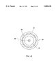
- FIG. 7 shows the valving arrangement for a pressure cell similar to the one shown in the cartridge of FIGS. 6A and 6B;
- FIG. 8 shows an exploded view of a pressure cell vertical cross-section
- FIG. 9 shows a top view of a second mounting plate of a pressure cell having an alternate arrangement of plate holes.
- FIG. 10 shows an electrophoretic apparatus in accordance with the present invention.
- FIG. 1 presents a schematic illustrating the use of a device in accordance with the present invention.
- a cartridge 30 of the present invention comprises a plurality of capillary tubes 32 having substantially the same length.
- the capillary tubes extend between a sample-side connection array 34 and gel side connection array 36.
- the capillary tubes 32 terminate on the sample-side in an array of first capillary ends 38 and on the gel side in an array of second capillary ends 40.
- each of the capillary tubes 32 in FIG. 1 extends through individual plate holes in a base member 42, which preferably is formed from polycarbonate, or acrylic or the like.
- a base member 42 which preferably is formed from polycarbonate, or acrylic or the like.
- each array of capillary ends may be retained in a separate mounting plate having the plate holes, and each of the mounting plates may then be fixed to a base member.
- one or more capillary tubes may be collected together and sent through a common hole, or even no hole at all.
- thermoelectric element 44 which is mounted on the base member 42.
- the thermoelectric element is arranged on either side of a window region 46.
- the thermoelectric element is used to control the temperature of the capillary tubes within a predetermined range. It should be evident to one skilled in the art that the thermoelectric element 42 may be comprised of two or more individual elements. It should also be evident that alternate temperature control means such as circulating fluid systems, and air convection may also be used to control the temperature.
- the capillary tubes 32 are arranged parallel to one another, side by side, in the window region 46.
- the length of each capillary tube from its first capillary end to the window region 46 is substantially the same for all the capillary tubes 32. This length is determined by the optimization of (i.e., minimum acceptable) sample run time, and the minimum acceptable resolution of the separated samples. Nominally, this length in on the order of 50-70 cm.
- the window region 46 represents the region allowing access to the parallel capillary tubes from incoming excitation light. It also allows access to outgoing fluorescence emission from the capillary tubes. Thus, the window region 46 allows the bands 50 in the various capillary tubes to be detected.
- an excitation light source comprising a laser 52 and a prism 54 is used to focus a light beam 56 through the window region 46 and onto the capillary tubes 32.
- a fluoresced light beam 58 is then sensed by a CCD camera 60, which captures the bands 50.
- other illumination and detection means can also be used.
- FIG. 1 provides for the substantially simultaneous introduction of samples into the array of first capillary ends 38 of all the capillary tubes 32.
- the arrangement allows one to introduce the various samples by simultaneously dipping the array of first capillary ends 38 into the wells 62 of a sample-side microtitre tray 64 having a standard size, as described above.
- the individual capillary ends are spaced apart from one another such that they have a spatial arrangement which is substantially the same as, that of an array of wells belonging to a microtitre tray of standard size.
- the spacing between adjacent first capillary ends is approximately 0.9 cm and the entire array of first capillary ends has a footprint less than 7.5 cm ⁇ 11 cm, thus corresponding to a microtitre tray of standard size.
- the array of second capillary ends 40 is inserted into the wells 66 of a second microtitre tray 68, where they come into contact with a buffer solution 70, as known to those skilled in the art. As the wells 66 in the second tray 68 are separated from one another, the chance of cross-contamination among the second capillary ends 40 is reduced.
- a voltage source 72 is used to provide a voltage differential between the two arrays of capillary ends. As shown in FIG. 1, one voltage level is applied through individual leads 74 to each of the wells 62 of the first microtitre tray 64 and a second voltage level is applied in substantially the same manner through leads 76 to the wells 66 of the second tray 68. Thus, current flows through the leads 74, into the individual samples, through the first capillary ends 38, through the capillary tubes 32, through the second capillary ends 40, into the buffer 70 present in the wells 66 of the second microtitre tray 68, and finally through leads 76.
- FIGS. 2A and 2B shows a top and a side view of one embodiment of a cartridge 80 in accordance with the present invention.
- the cartridge has a base member 82 formed from polycarbonate, acrylic or the like.
- Mounted in the base member are first and second mounting plates 84, 86, respectively.
- these plates are formed from an electrically insulative material.
- first capillary ends 88 project from the bottom surface 90 of the first mounting plate 84 and an array of second capillary ends 92 project from the bottom surface 94 of the second mounting plate.
- the capillary tubes 96 pass through, and are retained in, plate holes formed in the plates 84, 86 and project from the top surfaces 98, 100 of the plates.
- each of the capillary tubes 96 is protected by a tube assembly 102 which is secured to a plate hole in the mounting plate, as it passes through the mounting plates.
- the tube assemblies each with its associated capillary tubes, form a rectangular array of 8 rows and 12 columns as they emerge from the plates 84, 86.
- the spacing between adjacent plate holes in which the assemblies 102 are held, and the spacing of adjacent capillary ends 88, 92 correspond to the spacing of adjacent wells in a microtitre tray of standard size.
- adjacent capillary ends are separated by approximately 0.9 cm and the entire array of capillary ends, and thus the array of plate holes through which the capillary tubes 96 pass, form a footprint no larger than about 7.5 cm ⁇ 11.0 cm.
- each mounting plate 84, 86 is provided with first and second enclosures designated by reference numerals 104, 106, respectively.
- each of the enclosures is provided with an inlet 108 and an outlet 110.
- the outlet 110 of the first enclosure is connected to the inlet 108 of the second enclosure by plastic tubing 112.
- the inlet 108 of the first enclosure is connected to a first plastic shut off valve 114 while the outlet 110 of the second enclosure is connected to a second plastic shut off valve 116.
- the plastic shut off valves 114, 116 are connected, in turn, to respective first and second quick disconnects 118, 120.
- the cartridge 80 can be connected to a pump assembly 122 which is arranged to circulate a temperature-controlled liquid coolant through the enclosures 104, 106.
- the cartridge's first disconnect 118 is connected to the output 124 of the pump assembly 122 while the second disconnect 120 is connected to the input 126 of the pump assembly 122.
- Such an arrangement maintains the temperature of those portions of the capillary tubes 96 projecting from the upper surfaces 98, 100 of the mounting plates and present in the enclosures 104, 106.
- the mounting plates 84, 86 must form a liquid-tight seal with the base member 82.
- a liquid-tight seal must also be formed between the plate holes and the tube assemblies 102 and/or the capillary tubes 96 themselves.
- thermoelectric temperature control means 128, or the equivalent is arranged on either side of a window region 130 of the capillary tubes 96 to control the temperature of the capillary tubes when they are no longer within the enclosures 104, 106.
- the capillaries 96 are arranged parallel to one another so that they may be read by detection means.
- the base member 82 is provided with an opening 132 above which the window region 130 is situated. This allows for at least one of illumination means or detection means to be placed below the base member from where they may be in a direct line of sight to the exposed capillary tubes 96.
- FIG. 3A shows a needle 140 used in forming a tube assembly 160 which can then be directly inserted into a mounting plate 162, as shown in FIG. 3B.
- the needle 140 comprises a metallic cannula 142.
- the cannula 142 is formed from stainless steel having an inner diameter of 0.064 in. and an outer diameter of 0.072 in.
- the cannula 142 is provided with a bevel 144 at the end which is dipped into a well.
- a coaxially arranged annular polyetheretherketone (PEEK) polymer tubing 146 which serves as a sleeve.
- the polymer tubing 146 has an inner diameter of about 0.006 in. and an outer diameter of 0.0625 in. Thus, the polymer tubing 146 can be comfortably inserted into cannula 142.
- a capillary tube 148 Running through the center of the tubing 146, along a longitudinal axis of the needle 140, is a capillary tube 148 which is associated with the needle 140.
- the capillary tube 148 is formed from fused silica and has an inner diameter of about 0.003 in. and an outer diameter of about 0.006 in. Thus, the capillary tube 148 fits snugly into the polymer tubing 146.
- the capillary tube 148 terminates in an end 150 which is substantially across from the end 152 of the cannula 142. Thus, the spacing between the two ends 150, 152 is about 0.035 in.
- An UV-cured, medical-grade epoxy sealant 154 is used at both ends of the polymer tubing 146 to secure it and the capillary tube 148 to the cannula 142.
- the epoxy sealant 154 forms an air- and liquid-tight seal through the cannula 142.
- the epoxy sealant ensures that the polymer tubing 146 is not exposed to the environment, and also ensures that the capillary tube 148 does not come into direct contact with the cannula 142.
- a needle may be formed in ways other than the one depicted in FIG. 3A.
- the needle may simply comprise a capillary tube encased in a poured or coextruded plastic material which, in turn, is secured to a metallic strip.
- Other arrangements are also possible.
- FIG. 3B shows a hollow, high pressure compression fitting 164 formed from nylon into which the needle 140 is inserted to complete the tube assembly 160.
- the needle 140 can be secured to the cylindrical inner walls of the compression fitting with an epoxy sealant.
- Each tube assembly 160 is then inserted into a plate hole 166 tapped in the mounting plate 162 and the plate hole 116, too, can be sealed with epoxy.
- an air- and liquid-tight seal is provided between the bottom surface 168 and the top surface 170 of the mounting plate 162, allowing the mounting plate to withstand a positive pressure applied on its bottom surface in a region where the plate holes securing the tube assemblies are situated.
- Such a fitting-less approach can improve the structural integrity of the mounting plate 162 due to the reduced size of the plate holes. It may also provide a better air- and liquid-tight seal since there are fewer interfaces in which epoxy sealant is used.
- each plate hole has one capillary tube retained therein.
- the array of plate holes preferably has a spatial arrangement corresponding to that of the wells of a microtitre tray of standard size. However, it may be possible to form the plate holes off-center, and then angle the capillary ends.
- an array of capillary ends in the desired configuration without forming holes in a mounting plate 162.
- this can be done by gluing or clamping the individual capillaries to a mounting plate so that their ends are arranged in the desired configuration.
- the capillaries may be secured together so that their ends remain in the desired configuration in a poured acrylic or the like. What is important is that the spacing of the capillary ends in the array correspond to the spacing of the wells in the microtitre tray of standard size.
- a conductive plate 172 may be secured to the mounting plate 162 by screws, adhesives, or other conventional means.
- the conductive plate 172 is formed with an array of conductive holes 174 which corresponds to the plate holes 166 in the mounting plate.
- Each of the conductive holes 174 is formed by an H-shaped slit which forms a pair of tabs 176, 178 between the legs of the "H".
- the voltage differential may be delivered to the first capillary ends through other means as well.
- voltage leads may be connected directly to each needle.
- individual leads may be dipped into the liquid in each well.
- Another alternative is to deliver the voltage through a metallic coating, such as gold, deposited on the exterior of only the terminal portion of each capillary tube, where it contacts the liquid in the well.
- the voltage may be delivered directly to the wells through one or more leads, as described earlier.
- One skilled in the art can readily formulate alternative approaches to delivering a voltage to the first capillary end.
- FIG. 4 shows a monitor plate 190 which can be used with the cartridge embodiment shown in FIGS. 2A and 2B.
- the needles of at least the first mounting plate 84 are provided with a conductive plate 172 described above.
- the needles of the second mounting plate 86 can be provided with a monitor plate 190.
- the monitor plate has an array of monitor holes 192.
- the array of monitor holes is aligned with the second array of plate holes formed in the second mounting plate 86.
- Each monitor hole 192 is formed with an isolated electrical contact 194 which is electrically connected to a monitor plate connector 196 by an individual lead 198.
- Each needle in the second mounting plate 86 contacts a corresponding electrical contact 194 in the monitor plate.
- the purpose of the monitor plate is to provide a means for gauging the presence of electrical conductivity between any needle in the second mounting plate 86 and the needles of the first mounting plate 84.
- the monitor plate 190 can be secured to mounting plate 86 in much the same manner as the conductive plate 172. What is important is that each of the electrical contacts 194 connects to only one needle in the second mounting plate.
- FIG. 5 shows a cartridge 200 having a first 202 and a second 204 array of needles arranged above a first 206 and a second 208 carousel, each array positioned above a portion of a respective carousel.
- a CCD camera 210 is positioned above a portion of the cartridge between the two to detect bands in the capillary tubes (not shown in FIG. 5).
- Each carousel 206, 208, has eight platforms 212, on each of which a microtitre tray having a standard size is placed.
- the wells in each of these trays hold one or more liquids such as samples, gels, buffer solutions, acidic solutions, basic solutions, etc.
- the first carousel holds 6 sample trays 214, 1 buffer tray and 1 waste tray, a sample tray being positioned underneath the first needle array 202.
- the second carousel holds a pair of acidic solution trays 220, a pair of basic solution trays 222, a pair of waste trays 224, one of which is positioned underneath the second needle array 204, a buffer solution tray 226, and a gel tray 228.
- the first carousel 206 is the sample-side carousel
- the second carousel 208 is the gel-side carousel.
- the cartridge is removably mounted to an automated electrophoretic apparatus.
- a lifting means raises and lowers the platform 212 which is under either of the two needle arrays 202, 204.
- the needles in these arrays, and their associated capillary ends are dipped into the contents of each well of that microtitre tray.
- the platform under either of the needle arrays is lowered, the carousel associated with that platform may be rotated so that a different platform 212 holding a different microtitre tray, can be raised.
- a high voltage for brief period of time, on the order of 20-40 seconds, to cause the samples to migrate into the first capillary ends.
- a high voltage for this purpose, however, may be size-selective. That is, smaller molecules are more likely to enter the first capillary ends, potentially distorting the subsequent electrophoresis analysis.
- the various microtitre trays are loaded with the designated buffer solutions, gels, samples, etc.
- gel tray 228 in carousel 208 is raised and gel is introduced into the capillary tubes (not shown in FIG. 5) through second capillary ends (hidden in FIG. 5) associated with the second needle array 204.
- the gel tray 228 is then lowered.
- a sample tray 214 in carousel 206 is then raised, and sample is introduced through the first capillary ends (hidden in FIG. 5) associated with the first needle array 202.
- the sample tray 214 is then lowered.
- Carousels 206 and 208 are then rotated to position buffer trays 216 and 226 under their respective needle arrays 202 and 204.
- a voltage differential is then applied across the two needle arrays to perform the electrophoresis run.
- the cartridge may be reconditioned. This is done by flushing out the gel and samples from the previous run under pressure and cleaning the capillary tubes using the acidic 220 and/or basic 222 solutions. The cartridge is then ready for re-use, allowing the samples in another one of the sample trays 214 to be tested.
- the carousels 204, 206 may be formed with a different number of platforms. It should also be obvious that one can use a linear, or rectangular, or other arrangement of such platforms. All that is required is a storage and positioning system which allows a first particular microtitre tray to be brought to the first needle array 206, and a second particular microtitre tray to be brought under the second needle array 208.
- FIGS. 6A and 6B present a side and a top view, respectively, of a cartridge 280 having a first mounting plate 282 in which the array of plate holes in the first mounting plate 282 is rotated by 90°. Otherwise, the arrangement for connecting the capillary tubes to the first mounting plate is substantially the same as previously described.
- the first capillary ends formed in an array with the desired spacing project from the bottom surface of the first mounting plate 282, and are retained in plate holes formed in the first mounting plate.
- the second mounting plate 284 is not the same as in the previous cartridge embodiment.
- the second mounting plate 282 serves as a pressure containment member of a pressure cell 286 having substantially cylindrical exterior walls.
- FIG. 6A does not show all the capillary tubes on the first mounting plate, nor any capillary tubes at all on the second mounting plate 284. It is to be understood, however, that all the capillary tubes are present.
- the second mounting plate has a radially symmetric, beveled surface 288 in which a plurality of plate holes 290 are formed.
- Each of these plate holes 290 is fitted with a section of PEEK polymer tubing 292 in which the capillaries are encased using an UV-cured epoxy, as described before, to form an air- and liquid-tight seal in the plate holes 290.
- the capillary tubes pass through the PEEK polymer tubing and a second end of each capillary tube communicates with an interior cavity of the pressure cell.
- each capillary tube 294 is retained in a plate hole 290 in an air- and liquid-tight manner, and that the capillary tube's second end communicates with an interior cavity of the pressure cell 286.
- this cartridge 280 is provided with thermoelectric control means 298, enclosures 300, 302, and its capillary tubes are arranged in parallel along at least a portion of a window region 304.
- the enclosures 300, 302 can be provided with inlets and outlets and the like for circulating a coolant, as was the case with the other cartridge 80.
- the second mounting plate 284 has a truncated cone-shaped upper portion terminating in a flat top 310.
- the curved, conical surface 288 in which the plate holes 290 are formed is advantageous for reasons of structural integrity when a high positive pressure is applied from underneath the second mounting plate. Also, placing the plate holes 290 on such a surface allows them to be placed farther apart, a feature which also enhances the structural integrity of the pressure cell 286.
- the pressure cell 286 is secured to the base member of the cartridge 280 and projects through the bottom of the base member.
- This arrangement allows the pressure cell 286 to be provided with an inlet 312 and an outlet 314 arranged on opposite sides of its cylindrical exterior walls.
- the inlet could just as easily be formed in the flat top portion 310 of the second plate 284, and the outlet formed in the bottom surface of a lower portion 316 of the pressure cell 286.
- the pressure cell could rest on the base member, rather than project through its bottom, with a pipe fitting connected to the outlet through a hole formed in the base member, which hole is then sealed.
- FIG. 7 shows a valving arrangement for a pressure cell 320 which has an inlet 322 at its top surface 324, but otherwise is substantially similar to the pressure cell 286. Aside from the inlet 322, the pressure cell 320 is also provided with an outlet 326, which is connected to a waste valve 328. The waste valve 328 is opened to expel the contents of an interior cavity of the pressure cell 320.
- Access to the inlet is 322 controlled by a shut-off valve 330.
- Liquids can be passed through the inlet 322 into the pressure cell 320 with the use of a pump 332.
- the pump is a high pressure liquid chromatography (HPLC) pump having a pumping capacity of 4-40 milliliters per minute, at a pressure of about 2000 psi.
- HPLC high pressure liquid chromatography
- the pump 332 is connected to a multi-valve manifold 334 which selectively allows one of four liquids to be pumped into the pressure cell.
- the four liquids are held in separate containers 336, 338, 340, 342, which respectively hold gel, a buffer solution, an acidic solution, and a basic solution. Additional containers holding the same liquids may be held in reserve, or connected in series with these, so as to increase the total supply.
- the waste valve 328, the shut-off valve 330, the pump 332 and the multi-valve manifold 334 are all under the direction of a controller, preferably a microcomputer, or equivalent.
- a controller preferably a microcomputer, or equivalent.
- the contents of an interior cavity of the pressure cell are regulated by the controller.
- Such a controller may also receive inputs from various pressure and temperature monitors and other sensors to prevent damage to the pressure cell 320.
- the interior cavity of the pressure cell 320 is filled by means of the pump 332. This forces the pumped liquid into the second capillary ends which communicate with the interior cavity of the pressure cell 320.
- the pump 332 By filling the array of first capillary ends and the pressure cell 320 with the appropriate fluids in the appropriate sequence, one may perform the electrophoresis operations, much as described above with regard to the apparatus of FIG. 5.
- FIG. 8 shows an exploded cross-section of a pressure cell 350, similar to the pressure cell 286 in the cartridge 280.
- pressure cell 350 is preferably formed from aluminum or stainless steel.
- the pressure cell 350 is provided with a threaded inlet 352 formed on the top surface 354 of its upper portion 356, which upper portion comprises the second mounting plate.
- the pressure cell 350 is also provided with a threaded outlet 358 on the bottom surface 360 of its lower portion 362. High pressure pipe fittings can be screwed into the threads of the inlet 352 and the outlet 358.
- the upper portion 356 and the lower portion 362 are held together by a plurality of bolts (not shown) which are inserted through bolt holes 368 formed along the periphery of the bottom surface 360 of the lower portion 362. The bolts are then screwed into corresponding threaded holes 370 formed on the bottom surface 372 of the upper portion 356.
- An O-ring 364 partially fits into a rectangular channel 366 formed in the second mounting plate 356. The O-ring 364 provides a seal between the upper portion 356 and the lower portion 362. Instead of an O-ring, a gasket, or the like may be used to effect such a seal.
- a plurality of plate holes 376 are formed in the upper portion (second mounting plate). For simplicity, in FIG. 8, the plate holes 376 are only shown on one side of the upper portion 356. It should be understood, however, that they are also present on the other side.
- the plate holes 376 extend from a beveled surface 378 formed on the upper portion 356 to the interior cavity 374.
- Capillary tubes 380 are retained in these plate holes 376 and their second ends 382 communicate with the interior cavity 374.
- each capillary is encased in a section of PEEK polymer tubing which extends from a point within each plate hole 376, proximate to the interior cavity 374, to well outside the beveled surface 378.
- the PEEK tubing is not shown in FIG. 8. Nevertheless, it should be kept in mind that just the capillary tube, or a needle comprising a capillary tube, PEEK tubing and a cannula, can be inserted into each plate hole 376, assuming that it is suitably sized.
- an UV-cured epoxy sealant is used to seal the plate holes 376 at both ends so that they are air- and liquid-tight.
- the terminal portion 384 of each plate hole proximate to the interior cavity 374 is tapped or roughened. This provides a surface to which the epoxy sealant bonds more readily during assembly.
- a liquid held within the interior cavity 374 is in contact with the material forming the interior cavity.
- the liquid is also in contact with the second capillary end 382
- grounding the pressure cell 350 through a contact formed thereon applies the ground to the interior cavity 374, completing the circuit necessary to perform the electrophoresis.
- the potential of the pressure cell 350 may be allowed to float. This allows one to apply a high voltage to the pressure cell 350, rather than to the needles associated with the first capillary ends.
- FIG. 9 shows an alternate arrangement for the plate holes 390 in a second mounting plate 392 having a top surface 394 and an inlet 396.
- each set 398 of three plate holes is offset at an angle relative to the center of the top surface 394. This provides for a maximum spacing between the plate holes. From a structural integrity point of view, such an arrangement may be preferable to having the plate holes arranged radially, in a spoke-like fashion, as shown in FIG. 6B.
- FIG. 10 shows an electrophoretic apparatus 400 designed for use with a capillary cartridge formed in accordance with FIGS. 6-9.
- the apparatus comprises a user interface 402, shown as a video display terminal and keyboard, which communicates with a controller 404, which preferably is a microprocessor-based computer, or the like.
- the user interface 402 allows a user to enter commands, receive status information, and view the collected data.
- the apparatus 400 also comprises a data processing computer 406, which receives, stores and processes video signals from a CCD camera 408.
- the data processing computer 406 is provided with optical 410 and/or magnetic 412 read/write data storage means. Resident in the data processing computer 406 are signal and image processing software to analyze the signal data from the camera 400.
- the data processing computer 406 is connected to the controller 404, and responds to requests from the latter, exchanging data and control information, as needed.
- the apparatus 400 is further provided with a high-voltage power supply 414 which provides the necessary voltage to be applied across the ends of the capillary tubes.
- the power supply's operation is directed by the controller 404.
- the controller 404 also directs the operation of a pump interface 416, which comprises a number of electronic switches.
- the pump interface 416 regulates the operation of a solenoid valve 418.
- the solenoid valve 418 connects a gas inlet 420 which is connected to an inert gas source, such as a pressurized helium tank, to the chamber 422.
- the pump interface 416 also regulates the operation of high pressure liquid chromatography (HPLC) pump 426.
- HPLC pump 426 under the direction of the controller, selectively supplies liquids in a gel container 428, a buffer solution container 430, an acid container 432, and a base container 434, to a pressure cell 436 of a cartridge 438 through a multi-valve manifold 440.
- a carousel 442 having a plurality of platforms 448 is turned by a rotor 444.
- a lifting means 446 such as a hydraulic pump or the like, raises and lowers a platform 448 positioned under a first mounting plate. This brings a microtitre tray 450 on the platform 448 towards and away from an array of capillary ends, as previously described.
- Both the rotor 444 and the lifting means are connected to, and driven by, the controller 404.
- the apparatus 400 also includes a light source 452, preferably a laser, which illuminates the capillary tubes 454, as directed by the controller 404.
- the light source 452 illuminates the capillary tubes 454 from below, through an opening in a base member of the cartridge 438, as previously described.
- a light shroud 456 covers the camera 408, the light source 452, and at least the window region of the capillary tubes 454, as the detection of the capillary bands is performed in the dark.
- the capillary tubes 454 are first cleaned and then loaded with gel through the pressure cell 436 by activating pump 452.
- the pump 452 is then turned off.
- a platform 448 carrying a microtitre tray 450 holding samples is raised by the lifting means 446. This forms a seal between the platform 448 and the underside of the chamber 422. It also dips the first capillary ends into the wells of the microtitre tray 450.
- the solenoid valve 418 is opened, allowing pressurized helium gas to enter through the inlet 420.
- the light source 452 and the camera 408 are used to simultaneously detect the bands in all the capillary tubes 454.
- the video signal data from the camera 408 are processed and stored in the computer 406.
- the processed data may then be presented on the user interface 402.
- the cartridge 438 may be reconditioned (i.e., cleaned) and prepared for another run.
Abstract
Description
Claims (35)
Priority Applications (5)
| Application Number | Priority Date | Filing Date | Title |
|---|---|---|---|
| US08/726,877 US5885430A (en) | 1996-10-04 | 1996-10-04 | Capillary tube holder for an electrophoretic apparatus |
| AU46655/97A AU4665597A (en) | 1996-10-04 | 1997-10-03 | Capillary tube holder for electrophoretic applications |
| EP97945453A EP1010006A1 (en) | 1996-10-04 | 1997-10-03 | Capillary tube holder for electrophoretic applications |
| PCT/US1997/017792 WO1998014773A1 (en) | 1996-10-04 | 1997-10-03 | Capillary tube holder for electrophoretic applications |
| US09/110,877 US5916428A (en) | 1996-10-04 | 1998-07-07 | Automated system for multi-capillary electrophoresis having a two-dimensional array of capillary ends |
Applications Claiming Priority (1)
| Application Number | Priority Date | Filing Date | Title |
|---|---|---|---|
| US08/726,877 US5885430A (en) | 1996-10-04 | 1996-10-04 | Capillary tube holder for an electrophoretic apparatus |
Related Child Applications (1)
| Application Number | Title | Priority Date | Filing Date |
|---|---|---|---|
| US09/110,877 Division US5916428A (en) | 1996-10-04 | 1998-07-07 | Automated system for multi-capillary electrophoresis having a two-dimensional array of capillary ends |
Publications (1)
| Publication Number | Publication Date |
|---|---|
| US5885430A true US5885430A (en) | 1999-03-23 |
Family
ID=24920390
Family Applications (2)
| Application Number | Title | Priority Date | Filing Date |
|---|---|---|---|
| US08/726,877 Expired - Lifetime US5885430A (en) | 1996-10-04 | 1996-10-04 | Capillary tube holder for an electrophoretic apparatus |
| US09/110,877 Expired - Lifetime US5916428A (en) | 1996-10-04 | 1998-07-07 | Automated system for multi-capillary electrophoresis having a two-dimensional array of capillary ends |
Family Applications After (1)
| Application Number | Title | Priority Date | Filing Date |
|---|---|---|---|
| US09/110,877 Expired - Lifetime US5916428A (en) | 1996-10-04 | 1998-07-07 | Automated system for multi-capillary electrophoresis having a two-dimensional array of capillary ends |
Country Status (1)
| Country | Link |
|---|---|
| US (2) | US5885430A (en) |
Cited By (39)
| Publication number | Priority date | Publication date | Assignee | Title |
|---|---|---|---|---|
| WO2000023796A1 (en) * | 1998-10-21 | 2000-04-27 | Spectrumedix Corporation | Method and apparatus for monitoring and displaying the status of a parallel capillary electrophoresis device |
| US6103083A (en) * | 1998-02-20 | 2000-08-15 | Tetragen | Capillary electrophoresis apparatus and method |
| US6113767A (en) * | 1998-04-24 | 2000-09-05 | Apogee Designs, Ltd. | Electrophoresis sequencing apparatus |
| US6120667A (en) * | 1997-01-16 | 2000-09-19 | Japan Science And Technology Corporation | Multi-capillary electrophoresis apparatus |
| WO2001053794A1 (en) * | 2000-01-18 | 2001-07-26 | Northeastern University | Parallel sample loading and injection device for multichannel microfluidic devices |
| WO2001067080A1 (en) * | 2000-03-07 | 2001-09-13 | Northeastern University | Parallel array of independent thermostats for column separations |
| US20010027919A1 (en) * | 1997-08-26 | 2001-10-11 | Hitachi, Ltd. | Electrophoresis analysis apparatus and sample vessel used therefor |
| US20020023839A1 (en) * | 2000-08-25 | 2002-02-28 | Ryoji Inaba | Method of electrophoresis, electrophoresis apparatus and capillary array |
| US6365024B1 (en) * | 1997-06-30 | 2002-04-02 | Spectrumedix Corporation | Motorized positioning apparatus having coaxial carrousels |
| US6428670B1 (en) * | 1999-05-12 | 2002-08-06 | The Institute Of Physical And Chemical Research | Gel charger for capillary column |
| US6461492B1 (en) * | 1998-11-30 | 2002-10-08 | The Institute Of Physical And Chemical Research | Capillary electrophoretic apparatus |
| US6475361B1 (en) | 1998-02-20 | 2002-11-05 | Tetragen Sa | Capillary electrophoresis apparatus having filling/refilling system and methods for use thereof |
| US6511843B2 (en) * | 2000-05-25 | 2003-01-28 | Nippon Sheet Glass Co., Ltd. | Glass capillary for DNA analysis and manufacturing method thereof, and DNA analyzer that uses the glass capillary |
| US6544396B1 (en) * | 2000-07-20 | 2003-04-08 | Symyx Technologies, Inc. | Multiplexed capillary electrophoresis system |
| US6547943B1 (en) * | 2000-05-25 | 2003-04-15 | Spectrumedix Llc | Capillary system providing multiple analysis of sample from same body of liquid |
| US6551557B1 (en) | 1998-07-07 | 2003-04-22 | Cartesian Technologies, Inc. | Tip design and random access array for microfluidic transfer |
| WO2003035260A1 (en) * | 2001-10-26 | 2003-05-01 | Sequenom, Inc. | Method and apparatus for high-throughput sample handling process line |
| US20030102221A1 (en) * | 2001-12-04 | 2003-06-05 | Miho Ozawa | Multi-capillary electrophoresis apparatus |
| US20030113233A1 (en) * | 2001-10-26 | 2003-06-19 | Elizabeth Nanthakumar | Resin dispensing device |
| US6627446B1 (en) * | 1998-07-02 | 2003-09-30 | Amersham Biosciences (Sv) Corp | Robotic microchannel bioanalytical instrument |
| US20030188971A1 (en) * | 1998-02-16 | 2003-10-09 | The Institute Of Physical And Chemical Research | Capillary cassette and method of manufacturing the same |
| US20030228241A1 (en) * | 1999-08-13 | 2003-12-11 | Legge Coulton Heath | Apparatus for liquid sample handling |
| US20030226756A1 (en) * | 2001-09-28 | 2003-12-11 | Ryoji Inaba | Multi-capillary array electrophoresis device |
| US20040000481A1 (en) * | 2002-05-17 | 2004-01-01 | Goudberg Johan R.P. | Capillary array and electrophoresis apparatus, and method |
| US20040031686A1 (en) * | 2000-01-18 | 2004-02-19 | Frantisek Foret | Parallel sample loading and injection device for multichannel microfludic devices |
| US20040041098A1 (en) * | 2002-09-04 | 2004-03-04 | Pong Lai | Micro fluorescent electrophoresis detection system |
| US20040040850A1 (en) * | 1997-10-24 | 2004-03-04 | Northeastern University | Multichannel microscale system for high throughput preparative separation with comprehensive collection and analysis |
| US20040144652A1 (en) * | 2002-12-12 | 2004-07-29 | Syozo Kasai | Capillary array apparatus, method of manufacturing the same, and electrophoresis analysis method |
| US20040173457A1 (en) * | 2002-12-20 | 2004-09-09 | Miller Arthur W. | Precision controlled thermostat for capillary electrophoresis |
| US20040251138A1 (en) * | 2003-03-31 | 2004-12-16 | Toshio Hanada | Capillary array and capillary electrophoresis apparatus |
| US20060049053A1 (en) * | 2000-04-12 | 2006-03-09 | Tomonari Morioka | Capillary array unit and electrophoresis based thereon |
| US20060099707A1 (en) * | 2004-11-09 | 2006-05-11 | Nelson Alan C | Automated cell preparation system and method |
| US7494809B2 (en) | 2004-11-09 | 2009-02-24 | Visiongate, Inc. | Automated cell sample enrichment preparation method |
| US20090071830A1 (en) * | 2007-07-24 | 2009-03-19 | Applied Biosystems Inc. | Systems and Methods for Isolating Nucleic Acids |
| EP2363025A1 (en) | 2003-03-27 | 2011-09-07 | PTC Therapeutics, Inc. | Targeting enzymes of the TRNA splicing pathway for identification of anti-fungal and/or anti-proliferative molecules |
| US20120247958A1 (en) * | 2011-04-01 | 2012-10-04 | Life Technologies Corporation | Gel processing systems for electrophoresis, imaging, and analysis, software and methods |
| US9976417B2 (en) | 2012-07-16 | 2018-05-22 | Schlumberger Technology Corporation | Capillary electrophoresis for reservoir fluid analysis at wellsite and laboratory |
| US10018590B2 (en) | 2013-08-15 | 2018-07-10 | Schlumberger Technology Corporation | Capillary electrophoresis for subterranean applications |
| JP2020101570A (en) * | 2017-03-29 | 2020-07-02 | 株式会社日立ハイテク | Capillary electrophoresis apparatus and constant temperature bath |
Families Citing this family (27)
| Publication number | Priority date | Publication date | Assignee | Title |
|---|---|---|---|---|
| US6027627A (en) * | 1997-06-30 | 2000-02-22 | Spectrumedix Corporation | Automated parallel capillary electrophoretic system |
| US6787111B2 (en) | 1998-07-02 | 2004-09-07 | Amersham Biosciences (Sv) Corp. | Apparatus and method for filling and cleaning channels and inlet ports in microchips used for biological analysis |
| US6352633B1 (en) * | 1999-08-31 | 2002-03-05 | Spectrumedix Corporation | Automated parallel capillary electrophoresis system with hydrodynamic sample injection |
| JP3896739B2 (en) * | 1999-10-29 | 2007-03-22 | 株式会社日立製作所 | Capillary electrophoresis device |
| JP4103302B2 (en) * | 2000-05-15 | 2008-06-18 | 株式会社日立製作所 | Electrophoresis apparatus using capillary array and sample plate assembly used therefor |
| US6974527B2 (en) * | 2000-06-06 | 2005-12-13 | Spectrumedix Llc | Multidimensional separations employing an array of electrophoresis channels |
| US20090118139A1 (en) * | 2000-11-07 | 2009-05-07 | Caliper Life Sciences, Inc. | Microfluidic method and system for enzyme inhibition activity screening |
| US6783649B2 (en) * | 2000-12-01 | 2004-08-31 | Cetek Corporation | High throughput capillary electrophoresis system |
| US7070682B2 (en) * | 2001-01-16 | 2006-07-04 | Cheng Lee | Microfluidic apparatus for performing gel protein extractions and methods for using the apparatus |
| WO2002059592A2 (en) | 2001-01-26 | 2002-08-01 | Biocal Technology, Inc. | Optical detection in a multi-channel bio-separation system |
| WO2002059564A2 (en) * | 2001-01-26 | 2002-08-01 | Syngenta Participations Ag | Multicapillary fraction collection system and method |
| US7309409B2 (en) * | 2001-01-26 | 2007-12-18 | Biocal Technology, Inc. | Multi-channel bio-separation cartridge |
| US6929730B2 (en) * | 2001-05-01 | 2005-08-16 | Cheng Sheng Lee | Two dimensional microfluidic gene scanner |
| US7641780B2 (en) | 2001-05-01 | 2010-01-05 | Calibrant Biosystems, Inc. | Two-dimensional microfluidics for protein separations and gene analysis |
| US6974526B2 (en) * | 2001-05-01 | 2005-12-13 | Calibrant Biosystems, Inc. | Plastic microfluidics enabling two-dimensional protein separations in proteome analysis |
| DK1410029T3 (en) * | 2001-07-16 | 2008-01-07 | Protein Forest Inc | Arrays of buffers for analysis of biomolecules at their isoelectric point |
| US6969489B2 (en) * | 2001-08-24 | 2005-11-29 | Cytoplex Biosciences | Micro array for high throughout screening |
| DE60217393T2 (en) * | 2001-11-27 | 2007-10-18 | Cellectricon Ab | METHOD FOR THE COMBINED PARALLEL INTRODUCTION OF AGENTS AND ELECTROPORATION FOR CELL STRUCTURES AND USE THEREOF |
| US7208072B2 (en) * | 2002-01-18 | 2007-04-24 | Biocal Technology, Inc. | Multi-segment cartridge for bio-separation with multiplexed fluorescence detection |
| AU2003205132A1 (en) * | 2002-02-12 | 2003-09-04 | Celectricon AB | Systems and methods for rapidly changing the solution environment around sensors |
| AU2003257040A1 (en) * | 2002-07-29 | 2004-02-16 | David P. Dumas | Transparent polymer support for electrophoresis and electrochromatography and related methods |
| US20050072674A1 (en) * | 2003-10-03 | 2005-04-07 | Agencourt Bioscience Corporation | Method and device for introducing a sample into an electrophoretic apparatus |
| US20060070880A1 (en) * | 2004-08-31 | 2006-04-06 | Applera Corporation | Methods and apparatus for manipulating separation media |
| FI20050333A0 (en) * | 2005-03-30 | 2005-03-30 | Valtion Teknillinen | High temperature on-line capillary electrophoresis device |
| US20080156080A1 (en) * | 2007-01-02 | 2008-07-03 | Calibrant Biosystems, Inc. | Methods and systems for multidimensional concentration and separation of biomolecules using capillary isotachophoresis |
| US20080160629A1 (en) * | 2007-01-02 | 2008-07-03 | Calibrant Biosystems, Inc. | Methods and systems for off-line multidimensional concentration and separation of biomolecules |
| JP5830230B2 (en) * | 2010-07-20 | 2015-12-09 | アークレイ株式会社 | Analysis apparatus and analysis method |
Citations (15)
| Publication number | Priority date | Publication date | Assignee | Title |
|---|---|---|---|---|
| GB2113903A (en) * | 1982-01-12 | 1983-08-10 | Standard Telephones Cables Ltd | Cable manufacture |
| EP0257855A2 (en) * | 1986-08-04 | 1988-03-02 | E.I. Du Pont De Nemours And Company | Cable having a corrugated septum |
| WO1989004966A1 (en) * | 1987-11-25 | 1989-06-01 | Norberto Guzman | Automated capillary electrophoresis apparatus |
| DE9011484U1 (en) * | 1990-08-07 | 1990-10-11 | Ernst & Engbring Gmbh, 4353 Oer-Erkenschwick, De | |
| US5198091A (en) * | 1988-04-29 | 1993-03-30 | Beckman Instruments, Inc. | Capillary cartridge for electrophoresis |
| US5274240A (en) * | 1990-01-12 | 1993-12-28 | The Regents Of The University Of California | Capillary array confocal fluorescence scanner and method |
| US5356525A (en) * | 1993-04-16 | 1994-10-18 | Beckman Instruments, Inc. | Sample handling system |
| WO1994029713A1 (en) * | 1993-06-03 | 1994-12-22 | Beckman Instruments, Inc. | Capillary and capillary retaining system |
| WO1994029712A1 (en) * | 1993-06-03 | 1994-12-22 | University Of Alberta | Multiple capillary biochemical analyzer |
| US5413686A (en) * | 1992-07-17 | 1995-05-09 | Beckman Instruments, Inc. | Multi-channel automated capillary electrophoresis analyzer |
| US5436130A (en) * | 1992-03-19 | 1995-07-25 | The Regents Of The University Of California | Multiple tag labeling method for DNA sequencing |
| US5498324A (en) * | 1993-02-05 | 1996-03-12 | Iowa State University Research Foundation, Inc. | Multiplexed fluorescence detector system for capillary electrophoresis |
| EP0723149A2 (en) * | 1995-01-19 | 1996-07-24 | Hitachi, Ltd. | Capillary array electrophoresis system |
| US5605666A (en) * | 1993-04-16 | 1997-02-25 | Beckman Instruments, Inc. | Capillary retaining system |
| US5730850A (en) * | 1993-04-23 | 1998-03-24 | Hitachi, Ltd. | Capillary array electrophoresis system |
Family Cites Families (4)
| Publication number | Priority date | Publication date | Assignee | Title |
|---|---|---|---|---|
| US5085757A (en) * | 1987-11-25 | 1992-02-04 | Northeastern University | Integrated temperature control/alignment system for high performance capillary electrophoretic apparatus |
| JP2785530B2 (en) * | 1991-09-13 | 1998-08-13 | 株式会社日立製作所 | Electrophoresis device |
| US5240585A (en) * | 1992-07-14 | 1993-08-31 | Hewlett-Packard Company | Conductive bridge for external control of electroosmotic flow |
| US5332480A (en) * | 1993-06-16 | 1994-07-26 | University Of Iowa Research Foundation | Capillary bed electrophoresis |
-
1996
- 1996-10-04 US US08/726,877 patent/US5885430A/en not_active Expired - Lifetime
-
1998
- 1998-07-07 US US09/110,877 patent/US5916428A/en not_active Expired - Lifetime
Patent Citations (16)
| Publication number | Priority date | Publication date | Assignee | Title |
|---|---|---|---|---|
| GB2113903A (en) * | 1982-01-12 | 1983-08-10 | Standard Telephones Cables Ltd | Cable manufacture |
| EP0257855A2 (en) * | 1986-08-04 | 1988-03-02 | E.I. Du Pont De Nemours And Company | Cable having a corrugated septum |
| WO1989004966A1 (en) * | 1987-11-25 | 1989-06-01 | Norberto Guzman | Automated capillary electrophoresis apparatus |
| US5198091A (en) * | 1988-04-29 | 1993-03-30 | Beckman Instruments, Inc. | Capillary cartridge for electrophoresis |
| US5274240A (en) * | 1990-01-12 | 1993-12-28 | The Regents Of The University Of California | Capillary array confocal fluorescence scanner and method |
| DE9011484U1 (en) * | 1990-08-07 | 1990-10-11 | Ernst & Engbring Gmbh, 4353 Oer-Erkenschwick, De | |
| US5436130A (en) * | 1992-03-19 | 1995-07-25 | The Regents Of The University Of California | Multiple tag labeling method for DNA sequencing |
| US5413686A (en) * | 1992-07-17 | 1995-05-09 | Beckman Instruments, Inc. | Multi-channel automated capillary electrophoresis analyzer |
| US5498324A (en) * | 1993-02-05 | 1996-03-12 | Iowa State University Research Foundation, Inc. | Multiplexed fluorescence detector system for capillary electrophoresis |
| US5417925A (en) * | 1993-04-16 | 1995-05-23 | Beckman Instruments, Inc. | Capillary and capillary retaining system |
| US5356525A (en) * | 1993-04-16 | 1994-10-18 | Beckman Instruments, Inc. | Sample handling system |
| US5605666A (en) * | 1993-04-16 | 1997-02-25 | Beckman Instruments, Inc. | Capillary retaining system |
| US5730850A (en) * | 1993-04-23 | 1998-03-24 | Hitachi, Ltd. | Capillary array electrophoresis system |
| WO1994029712A1 (en) * | 1993-06-03 | 1994-12-22 | University Of Alberta | Multiple capillary biochemical analyzer |
| WO1994029713A1 (en) * | 1993-06-03 | 1994-12-22 | Beckman Instruments, Inc. | Capillary and capillary retaining system |
| EP0723149A2 (en) * | 1995-01-19 | 1996-07-24 | Hitachi, Ltd. | Capillary array electrophoresis system |
Cited By (77)
| Publication number | Priority date | Publication date | Assignee | Title |
|---|---|---|---|---|
| US6120667A (en) * | 1997-01-16 | 2000-09-19 | Japan Science And Technology Corporation | Multi-capillary electrophoresis apparatus |
| US6375819B1 (en) * | 1997-06-30 | 2002-04-23 | Spectrumedix Corporation | Fluid delivery system for capillary electrophoretic applications |
| US6365024B1 (en) * | 1997-06-30 | 2002-04-02 | Spectrumedix Corporation | Motorized positioning apparatus having coaxial carrousels |
| US20010027919A1 (en) * | 1997-08-26 | 2001-10-11 | Hitachi, Ltd. | Electrophoresis analysis apparatus and sample vessel used therefor |
| US6740219B2 (en) * | 1997-08-26 | 2004-05-25 | Hitachi, Ltd. | Electrophoresis analysis apparatus and sample vessel used therefor |
| US20040163962A1 (en) * | 1997-08-26 | 2004-08-26 | Hitachi, Ltd. | Electrophoresis analysis apparatus and sample vessel used therefor |
| US6325908B1 (en) * | 1997-08-26 | 2001-12-04 | Hitachi, Ltd. | Electrophoresis analysis apparatus and sample vessel used therefor |
| US7578915B2 (en) * | 1997-10-24 | 2009-08-25 | Northeastern University | Multichannel microscale system for high throughput preparative separation with comprehensive collection and analysis |
| US20040040850A1 (en) * | 1997-10-24 | 2004-03-04 | Northeastern University | Multichannel microscale system for high throughput preparative separation with comprehensive collection and analysis |
| US7014745B2 (en) * | 1998-02-16 | 2006-03-21 | The Institute Of Physical And Chemical Research | Capillary cassette and method of manufacturing the same |
| US20030188971A1 (en) * | 1998-02-16 | 2003-10-09 | The Institute Of Physical And Chemical Research | Capillary cassette and method of manufacturing the same |
| US20060113191A1 (en) * | 1998-02-16 | 2006-06-01 | The Institute Of Physical And Chemical Research | Capillary cassette and method of manufacturing the same |
| US7531076B2 (en) | 1998-02-16 | 2009-05-12 | The Institute Of Physical And Chemical Research | Capillary cassette and method of manufacturing the same |
| US6103083A (en) * | 1998-02-20 | 2000-08-15 | Tetragen | Capillary electrophoresis apparatus and method |
| US6475361B1 (en) | 1998-02-20 | 2002-11-05 | Tetragen Sa | Capillary electrophoresis apparatus having filling/refilling system and methods for use thereof |
| US6113767A (en) * | 1998-04-24 | 2000-09-05 | Apogee Designs, Ltd. | Electrophoresis sequencing apparatus |
| US6627446B1 (en) * | 1998-07-02 | 2003-09-30 | Amersham Biosciences (Sv) Corp | Robotic microchannel bioanalytical instrument |
| US20040262162A1 (en) * | 1998-07-02 | 2004-12-30 | Roach David J. | Robotic microchannel bioanalytical instrument |
| US20040072365A1 (en) * | 1998-07-07 | 2004-04-15 | Don Rose | Method and apparatus for liquid dispensing |
| US6551557B1 (en) | 1998-07-07 | 2003-04-22 | Cartesian Technologies, Inc. | Tip design and random access array for microfluidic transfer |
| US7736591B2 (en) | 1998-07-07 | 2010-06-15 | Biodot, Inc. | Method and apparatus for liquid dispensing |
| WO2000023796A1 (en) * | 1998-10-21 | 2000-04-27 | Spectrumedix Corporation | Method and apparatus for monitoring and displaying the status of a parallel capillary electrophoresis device |
| US6217731B1 (en) * | 1998-10-21 | 2001-04-17 | Spectrumedix Corporation | Method and apparatus for monitoring and displaying the status of a parallel capillary electrophoresis device |
| US6461492B1 (en) * | 1998-11-30 | 2002-10-08 | The Institute Of Physical And Chemical Research | Capillary electrophoretic apparatus |
| US6783650B2 (en) | 1998-11-30 | 2004-08-31 | The Institute Of Physical & Chemical Research | Capillary electrophoretic apparatus |
| US6428670B1 (en) * | 1999-05-12 | 2002-08-06 | The Institute Of Physical And Chemical Research | Gel charger for capillary column |
| US20030228241A1 (en) * | 1999-08-13 | 2003-12-11 | Legge Coulton Heath | Apparatus for liquid sample handling |
| US20040031686A1 (en) * | 2000-01-18 | 2004-02-19 | Frantisek Foret | Parallel sample loading and injection device for multichannel microfludic devices |
| US6939452B2 (en) | 2000-01-18 | 2005-09-06 | Northeastern University | Parallel sample loading and injection device for multichannel microfluidic devices |
| WO2001053794A1 (en) * | 2000-01-18 | 2001-07-26 | Northeastern University | Parallel sample loading and injection device for multichannel microfluidic devices |
| US20020157951A1 (en) * | 2000-03-07 | 2002-10-31 | Frantisek Foret | Parallel array of independent thermostats for column separations |
| US6929731B2 (en) | 2000-03-07 | 2005-08-16 | Northeastern University | Parallel array of independent thermostats for column separations |
| WO2001067080A1 (en) * | 2000-03-07 | 2001-09-13 | Northeastern University | Parallel array of independent thermostats for column separations |
| US20060049053A1 (en) * | 2000-04-12 | 2006-03-09 | Tomonari Morioka | Capillary array unit and electrophoresis based thereon |
| US7445701B2 (en) * | 2000-04-12 | 2008-11-04 | Hitachi Ltd. | Capillary array unit and electrophoresis based thereon |
| US6547943B1 (en) * | 2000-05-25 | 2003-04-15 | Spectrumedix Llc | Capillary system providing multiple analysis of sample from same body of liquid |
| US6511843B2 (en) * | 2000-05-25 | 2003-01-28 | Nippon Sheet Glass Co., Ltd. | Glass capillary for DNA analysis and manufacturing method thereof, and DNA analyzer that uses the glass capillary |
| US20030146096A1 (en) * | 2000-07-20 | 2003-08-07 | Symyx Technologies, Inc. | Method of cooling a multiplexed capillary electrophoresis system |
| US6544396B1 (en) * | 2000-07-20 | 2003-04-08 | Symyx Technologies, Inc. | Multiplexed capillary electrophoresis system |
| US7316770B2 (en) * | 2000-08-25 | 2008-01-08 | Hitachi, Ltd. | Method of electrophoresis, electrophoresis apparatus and capillary array |
| US20020023839A1 (en) * | 2000-08-25 | 2002-02-28 | Ryoji Inaba | Method of electrophoresis, electrophoresis apparatus and capillary array |
| US8246806B2 (en) | 2001-09-28 | 2012-08-21 | Applera Corporation | Multi-capillary array electrophoresis device |
| US8043493B2 (en) | 2001-09-28 | 2011-10-25 | Hitachi, Ltd. | Multi-capillary array electrophoresis device |
| US20030226756A1 (en) * | 2001-09-28 | 2003-12-11 | Ryoji Inaba | Multi-capillary array electrophoresis device |
| US20070175761A1 (en) * | 2001-09-28 | 2007-08-02 | Ryoji Inaba | Multi-capillary array electrophoresis device |
| US7250098B2 (en) | 2001-09-28 | 2007-07-31 | Applera Corporation | Multi-capillary array electrophoresis device |
| US20070158195A1 (en) * | 2001-09-28 | 2007-07-12 | Ryoji Inaba | Multi-capillary array electrophoresis device |
| US7159740B2 (en) | 2001-10-26 | 2007-01-09 | Sequenom, Inc. | Method and apparatus for parallel dispensing of defined volumes of solid particles |
| WO2003035260A1 (en) * | 2001-10-26 | 2003-05-01 | Sequenom, Inc. | Method and apparatus for high-throughput sample handling process line |
| US20030124735A1 (en) * | 2001-10-26 | 2003-07-03 | Sequenom, Inc. | Method and apparatus for parallel dispensing of defined volumes of solid particles |
| US20030111494A1 (en) * | 2001-10-26 | 2003-06-19 | Sequenom, Inc. | Method and apparatus for high-throughput sample handling process line |
| US20030113233A1 (en) * | 2001-10-26 | 2003-06-19 | Elizabeth Nanthakumar | Resin dispensing device |
| EP1451567A4 (en) * | 2001-12-04 | 2010-05-05 | Multi-capillary electrophoresis apparatus | |
| US20030102221A1 (en) * | 2001-12-04 | 2003-06-05 | Miho Ozawa | Multi-capillary electrophoresis apparatus |
| EP1451567A1 (en) * | 2001-12-04 | 2004-09-01 | Applera Corporation | Multi-capillary electrophoresis apparatus |
| WO2003048755A1 (en) * | 2001-12-04 | 2003-06-12 | Applera Corporation | Multi-capillary electrophoresis apparatus |
| US20030127328A1 (en) * | 2001-12-04 | 2003-07-10 | Nordman Eric S. | Multi-capillary electrophoresis apparatus |
| US7459068B2 (en) * | 2001-12-04 | 2008-12-02 | Applied Biosystems Inc. | Multi-capillary electrophoresis apparatus |
| US7361259B2 (en) | 2002-05-17 | 2008-04-22 | Applera Corporation | Capillary array and electrophoresis apparatus, and method |
| US20040000481A1 (en) * | 2002-05-17 | 2004-01-01 | Goudberg Johan R.P. | Capillary array and electrophoresis apparatus, and method |
| US20040041098A1 (en) * | 2002-09-04 | 2004-03-04 | Pong Lai | Micro fluorescent electrophoresis detection system |
| US6919571B2 (en) | 2002-09-04 | 2005-07-19 | Industrial Technology Research Institute | Micro fluorescent electrophoresis detection system |
| US20040144652A1 (en) * | 2002-12-12 | 2004-07-29 | Syozo Kasai | Capillary array apparatus, method of manufacturing the same, and electrophoresis analysis method |
| US20080302665A1 (en) * | 2002-12-12 | 2008-12-11 | Syozo Kasai | Capillary array apparatus, method of manufacturing the same, and electrophoresis analysis method |
| US7422672B2 (en) * | 2002-12-12 | 2008-09-09 | Hitachi High-Technologies Corporation | Capillary array apparatus, method of manufacturing the same, and electrophoresis analysis method |
| US20040173457A1 (en) * | 2002-12-20 | 2004-09-09 | Miller Arthur W. | Precision controlled thermostat for capillary electrophoresis |
| EP2363025A1 (en) | 2003-03-27 | 2011-09-07 | PTC Therapeutics, Inc. | Targeting enzymes of the TRNA splicing pathway for identification of anti-fungal and/or anti-proliferative molecules |
| US7438793B2 (en) * | 2003-03-31 | 2008-10-21 | Hitachi High-Technologies Corporation | Capillary array having load header |
| US20040251138A1 (en) * | 2003-03-31 | 2004-12-16 | Toshio Hanada | Capillary array and capillary electrophoresis apparatus |
| US20060099707A1 (en) * | 2004-11-09 | 2006-05-11 | Nelson Alan C | Automated cell preparation system and method |
| US7494809B2 (en) | 2004-11-09 | 2009-02-24 | Visiongate, Inc. | Automated cell sample enrichment preparation method |
| US20090071830A1 (en) * | 2007-07-24 | 2009-03-19 | Applied Biosystems Inc. | Systems and Methods for Isolating Nucleic Acids |
| US8568580B2 (en) * | 2007-07-24 | 2013-10-29 | Applied Biosystems, Llc | Systems and methods for isolating nucleic acids |
| US20120247958A1 (en) * | 2011-04-01 | 2012-10-04 | Life Technologies Corporation | Gel processing systems for electrophoresis, imaging, and analysis, software and methods |
| US9976417B2 (en) | 2012-07-16 | 2018-05-22 | Schlumberger Technology Corporation | Capillary electrophoresis for reservoir fluid analysis at wellsite and laboratory |
| US10018590B2 (en) | 2013-08-15 | 2018-07-10 | Schlumberger Technology Corporation | Capillary electrophoresis for subterranean applications |
| JP2020101570A (en) * | 2017-03-29 | 2020-07-02 | 株式会社日立ハイテク | Capillary electrophoresis apparatus and constant temperature bath |
Also Published As
| Publication number | Publication date |
|---|---|
| US5916428A (en) | 1999-06-29 |
Similar Documents
| Publication | Publication Date | Title |
|---|---|---|
| US5885430A (en) | Capillary tube holder for an electrophoretic apparatus | |
| US6027627A (en) | Automated parallel capillary electrophoretic system | |
| US6365024B1 (en) | Motorized positioning apparatus having coaxial carrousels | |
| US6063251A (en) | Electrically insulated capillary arrays for electrophoretic applications | |
| EP0581413B1 (en) | Multi-channel capillary electrophoresis system | |
| US6017765A (en) | Fluorescence detection capillary array electrophoresis analyzer | |
| US6787111B2 (en) | Apparatus and method for filling and cleaning channels and inlet ports in microchips used for biological analysis | |
| US6764648B1 (en) | Robotic microchannel bioanalytical instrument | |
| US5423966A (en) | On line ion contaminant removal apparatus and method for capillary electrophoresis | |
| JP3295497B2 (en) | Liquid vial operation device in analyzer | |
| EP2669669B1 (en) | Capillary unit for electrophoresis apparatus | |
| JP2004537713A (en) | High-throughput capillary electrophoresis system | |
| US5837116A (en) | Two dimensional electrophoresis apparatus | |
| US4986891A (en) | Automatic electrophoresis apparatus and method | |
| CA2295227C (en) | Automated parallel capillary electrophoretic system | |
| EP0397699B1 (en) | Automated capillary electrophoresis apparatus | |
| WO1998014773A1 (en) | Capillary tube holder for electrophoretic applications | |
| WO1998014773A9 (en) | Capillary tube holder for electrophoretic applications | |
| US20150241389A1 (en) | Multi-capillary cartridge for capillary electrophoresis | |
| US20060070880A1 (en) | Methods and apparatus for manipulating separation media | |
| US6547943B1 (en) | Capillary system providing multiple analysis of sample from same body of liquid | |
| US6572750B1 (en) | Hydrodynamic injector | |
| EP1818673A2 (en) | Capillary electrophoretic instrument and capillary array assembly | |
| JPH0674937A (en) | Capillary system electrophoresis method and device therefor and column used in the same | |
| JP3325257B2 (en) | Capillary electrophoresis device |
Legal Events
| Date | Code | Title | Description |
|---|---|---|---|
| AS | Assignment |
Owner name: PREMIER AMERICAN TECHNOLOGIES CORPORATION, PENNSYL Free format text: ASSIGNMENT OF ASSIGNORS INTEREST;ASSIGNORS:KERNAN, JOHN R.;KANE, THOMAS E.;REEL/FRAME:008329/0447 Effective date: 19961018 |
|
| AS | Assignment |
Owner name: SPECTRUMEDIX CORPORATION, PENNSYLVANIA Free format text: CHANGE OF NAME;ASSIGNORS:KERNAN, JOHN R.;KANE, THOMAS E.;REEL/FRAME:008719/0403 Effective date: 19970311 |
|
| AS | Assignment |
Owner name: I. REICH FAMILY LIMITED PARTNERSHIP, NEW YORK Free format text: SECURITY INTEREST;ASSIGNOR:SPECTRUMEDIX CORPORATION;REEL/FRAME:012066/0076 Effective date: 20010709 |
|
| FPAY | Fee payment |
Year of fee payment: 4 |
|
| AS | Assignment |
Owner name: SPECTRUMEDIX, LLC, PENNSYLVANIA Free format text: ASSIGNMENT OF ASSIGNORS INTEREST;ASSIGNOR:SPECTRUMEDIX CORPORATION;REEL/FRAME:013663/0939 Effective date: 20020408 |
|
| AS | Assignment |
Owner name: I. REICH FAMILY LIMITED PARTNERSHIP, NEW YORK Free format text: SECURITY AGREEMENT;ASSIGNOR:SPECTRUMEDIX LLC;REEL/FRAME:013718/0236 Effective date: 20020329 |
|
| FEPP | Fee payment procedure |
Free format text: PAYOR NUMBER ASSIGNED (ORIGINAL EVENT CODE: ASPN); ENTITY STATUS OF PATENT OWNER: LARGE ENTITY |
|
| FPAY | Fee payment |
Year of fee payment: 8 |
|
| AS | Assignment |
Owner name: APPLERA CORPORATION, CALIFORNIA Free format text: ASSIGNMENT OF ASSIGNORS INTEREST;ASSIGNOR:SPECTRUMEDIX LLC;REEL/FRAME:019965/0081 Effective date: 20070919 |
|
| AS | Assignment |
Owner name: SPECTRUMEDIX, LLC, PENNSYLVANIA Free format text: RELEASE OF SECURITY INTEREST AGREEMENT BY COURT ORDER;ASSIGNOR:I. REICH FAMILY LIMITED PARTNERSHIP;REEL/FRAME:021744/0285 Effective date: 20070918 |
|
| AS | Assignment |
Owner name: BANK OF AMERICA, N.A, AS COLLATERAL AGENT, WASHING Free format text: SECURITY AGREEMENT;ASSIGNOR:APPLIED BIOSYSTEMS, LLC;REEL/FRAME:021976/0001 Effective date: 20081121 Owner name: BANK OF AMERICA, N.A, AS COLLATERAL AGENT,WASHINGT Free format text: SECURITY AGREEMENT;ASSIGNOR:APPLIED BIOSYSTEMS, LLC;REEL/FRAME:021976/0001 Effective date: 20081121 |
|
| AS | Assignment |
Owner name: APPLIED BIOSYSTEMS INC.,CALIFORNIA Free format text: CHANGE OF NAME;ASSIGNOR:APPLERA CORPORATION;REEL/FRAME:023994/0538 Effective date: 20080701 Owner name: APPLIED BIOSYSTEMS, LLC,CALIFORNIA Free format text: MERGER;ASSIGNOR:APPLIED BIOSYSTEMS INC.;REEL/FRAME:023994/0587 Effective date: 20081121 Owner name: APPLIED BIOSYSTEMS INC., CALIFORNIA Free format text: CHANGE OF NAME;ASSIGNOR:APPLERA CORPORATION;REEL/FRAME:023994/0538 Effective date: 20080701 Owner name: APPLIED BIOSYSTEMS, LLC, CALIFORNIA Free format text: MERGER;ASSIGNOR:APPLIED BIOSYSTEMS INC.;REEL/FRAME:023994/0587 Effective date: 20081121 |
|
| FPAY | Fee payment |
Year of fee payment: 12 |
|
| AS | Assignment |
Owner name: APPLIED BIOSYSTEMS, INC., CALIFORNIA Free format text: LIEN RELEASE;ASSIGNOR:BANK OF AMERICA, N.A.;REEL/FRAME:030182/0677 Effective date: 20100528 |
|
| SULP | Surcharge for late payment | ||
| STCF | Information on status: patent grant |
Free format text: PATENTED CASE |
|
| AS | Assignment |
Owner name: APPLIED BIOSYSTEMS, LLC, CALIFORNIA Free format text: CORRECTIVE ASSIGNMENT TO CORRECT THE RECEIVING PARTY NAME PREVIOUSLY RECORDED AT REEL: 030182 FRAME: 0709. ASSIGNOR(S) HEREBY CONFIRMS THE SECURITY INTEREST;ASSIGNOR:BANK OF AMERICA, N.A.;REEL/FRAME:038026/0001 Effective date: 20100528 Owner name: APPLIED BIOSYSTEMS, LLC, CALIFORNIA Free format text: CORRECTIVE ASSIGNMENT TO CORRECT THE RECEIVING PARTY NAME PREVIOUSLY RECORDED AT REEL: 030182 FRAME: 0677. ASSIGNOR(S) HEREBY CONFIRMS THE SECURITY INTEREST;ASSIGNOR:BANK OF AMERICA, N.A.;REEL/FRAME:038026/0001 Effective date: 20100528 |