US5883971A - System and method for determining if a fingerprint image contains an image portion representing a smudged fingerprint impression - Google Patents
System and method for determining if a fingerprint image contains an image portion representing a smudged fingerprint impression Download PDFInfo
- Publication number
- US5883971A US5883971A US08/735,718 US73571896A US5883971A US 5883971 A US5883971 A US 5883971A US 73571896 A US73571896 A US 73571896A US 5883971 A US5883971 A US 5883971A
- Authority
- US
- United States
- Prior art keywords
- block
- pixels
- blocks
- foreground
- smudged
- Prior art date
- Legal status (The legal status is an assumption and is not a legal conclusion. Google has not performed a legal analysis and makes no representation as to the accuracy of the status listed.)
- Expired - Lifetime
Links
Images


Classifications
-
- G—PHYSICS
- G06—COMPUTING; CALCULATING OR COUNTING
- G06T—IMAGE DATA PROCESSING OR GENERATION, IN GENERAL
- G06T7/00—Image analysis
- G06T7/0002—Inspection of images, e.g. flaw detection
-
- G—PHYSICS
- G06—COMPUTING; CALCULATING OR COUNTING
- G06V—IMAGE OR VIDEO RECOGNITION OR UNDERSTANDING
- G06V40/00—Recognition of biometric, human-related or animal-related patterns in image or video data
- G06V40/10—Human or animal bodies, e.g. vehicle occupants or pedestrians; Body parts, e.g. hands
- G06V40/12—Fingerprints or palmprints
- G06V40/1347—Preprocessing; Feature extraction
-
- G—PHYSICS
- G06—COMPUTING; CALCULATING OR COUNTING
- G06T—IMAGE DATA PROCESSING OR GENERATION, IN GENERAL
- G06T2207/00—Indexing scheme for image analysis or image enhancement
- G06T2207/20—Special algorithmic details
- G06T2207/20021—Dividing image into blocks, subimages or windows
-
- G—PHYSICS
- G06—COMPUTING; CALCULATING OR COUNTING
- G06T—IMAGE DATA PROCESSING OR GENERATION, IN GENERAL
- G06T2207/00—Indexing scheme for image analysis or image enhancement
- G06T2207/30—Subject of image; Context of image processing
- G06T2207/30168—Image quality inspection
Definitions
- This invention relates to the field of image processing. More specifically, the invention relates to a system and method for processing fingerprint images and detecting smudged fingerprint images.
- a fingerprint of a person comprises a distinctive and unique ridge pattern structure.
- ridge pattern structure could be characterized by endings and bifurcations of the individual ridges. These features are popularly known as minutiae.
- An example fingerprint is shown in FIG. 1A.
- the minutiae for the fingerprint shown in FIG. 1A are shown in FIG. 1B as being enclosed by "boxes.”
- box 101B shows a bifurcation minutia of a bifurcated ridge 101A in FIG. 1A
- box 103B shows a ridge ending minutia of ridge 103A in FIG. 1A.
- minutiae on the ridges in fingerprints have directions (also called orientations) 105 associated with them.
- the direction of the minutia at a ridge end 103B is the direction in which the end of the ridge points.
- the direction of a bifurcation minutia 101B is the direction in which the bifurcated ridge points.
- Minutiae also have locations which are the positions of the minutiae on the fingerprint with respect to some coordinate system.
- the prevalent methods of fingerprint identification and verification methods are based on minutiae features. These systems need to process the fingerprint images to obtain accurate and reliable minutiae features to effectively determine or verify the identity of a person.
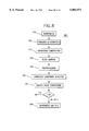
- FIG. 2 is a flow chart showing the steps generally performed by a typical prior art system 200.
- step 210 the image is acquired. This acquisition of the image could either be through a CCD camera and framegrabber interface or through a document scanner communicating with the primary computing equipment.
- relevant features minutia features are extracted (220). Not all of the features thus extracted are reliable. Some of the unreliable features are optionally pruned (step 230), e.g., manually edited. The resultant reliable features are used for matching two fingerprint images (step 240). That is, matching the acquired fingerprint image with stored minutiae representations of previously acquired fingerprint images.
- the unreliable features could be manually pruned visually by a human expert before the minutiae are used for matching (step 240).
- the fingerprint feature extraction, pruning, and matching system constitute the primary backbone of a typical minutiae-based automatic fingerprint identification systems (AFIS).
- AFIS minutiae-based automatic fingerprint identification systems
- the matching results are typically verified by a human expert (step 260 in FIG. 2). The verification may also be performed automatically.
- the following reference describes examples of the state of the prior art:
- FIG. 3 is a flow chart showing the prior art steps performed by a feature extraction process that are similar to some of the feature extraction proposed by Ratha, Jain, and Chen in the article mentioned above.
- a smoothing process is employed to reduce the pixel-wise noise (step 305).
- step 310 After the preprocessing stages, prior art systems find the directions of the ridge flow (step 310).
- the next important step in the processing is finding the exact location of the finger in the image, a process referred to as the foreground/background segmentation (step 315).
- the next step is to extract the ridges from the finger image (step 320).
- the ridges thus extracted are thick and might contain some noisy artifacts which do not correspond to any meaningful structures on the finger.
- the small structures could be safely removed (step 325).
- the longer structures are thinned to one-pixel width and then processed to remove any other artifacts using morphological operators (step 330).
- the locations and orientations of ridge endings and bifurcations are then extracted from the thinned structures (step 335) to obtain the minutiae.
- post-processing 340 is performed on the extracted minutiae.
- FIG. 4A is a prior art drawing of a typical fingerprint 400 of poor quality.
- region 410A is smudged. This smudging is common in fingerprints and can be caused by excessive pressure, sweat, excess ink, skin diseases, etc.
- FIG. 5A is a prior art drawing of another typical fingerprint of poor quality. Region 510A is caused by dryness of the finger in which case very little impression is produced in the image. Other reasons for poor quality regions include: poor optics, poor illumination, motion blur, etc.
- FIGS. 4B and 5B are prior art drawings of the unreliable minutia that result from the poor quality fingerprint in FIGS. 4A and 5A, respectively.
- Both images have excess minutiae (410B, 510B) from the smudging 410A and from the dryness 510A.
- These "noisy" fingers result in a number of unreliable minutiae, i.e., the minutiae do not uniquely identify their respective fingerprint and therefore can not be reliably matched to minutiae in a database that were extracted from an image of the same fingerprint.
- An object of this invention is an accurate and reliable fingerprint image preprocessing system that detects smudged fingerprint images.
- An object of this invention is an accurate and reliable fingerprint image preprocessing system that quantifies fingerprint image quality.
- Another object of this invention is an accurate and reliable fingerprint image pre-processing system that quantifies fingerprint image quality and detects images of poor quality due to smudginess of the imaging process.
- the invention is a computer system and method that determines a quality measure and smudginess of a fingerprint image by dividing the image into blocks of pixels.
- the invention permits the blocks to be created by down-sampling pixels from the original image.
- the blocks are marked to be directional (having a direction/orientation) or non-directional by determining whether there is a "prominent" number of pixels with the same direction within the block.
- the blocks are also determined to be within the foreground or background of the image.
- One embodiment of the invention makes these determinations by summing the intensity differences between the pixels in the block and their neighbors along one or more directions to classify the pixels as either foreground or background pixels.
- Blocks with over a threshold number of background pixels are background blocks, the other blocks are foreground blocks.
- Contiguous regions of blocks that are in the foreground and are directional are selected. In some embodiments, regions that have too few blocks are ignored.
- the quality measure is the ratio of the area of all these selected contiguous regions to the total area of the fingerprint image (i.e., the foreground.)
- the contribution of each of the blocks of the regions to the quality measure is weighted (i.e., given by) by a distance from a block containing a reference point (a block of reference) within the foreground. In a more preferred embodiment, this block of reference is located at the centroid of the foreground.
- Images are judged to be of poor quality if the quality measure is below a quality threshold and are judged to be of good quality if the quality measure is above the quality threshold. Poor quality images are further examined to determine if they correspond to wet fingers or other corrupting factors in the imaging process by determining whether there are a large number of "smudged" blocks in the images, i.e., there are a relatively large number of blocks whose contrast is very small.
- This smudge test begins by determining the mean intensity of pixels within each foreground block. For each foreground block, a mean intensity ( ⁇ ) of pixels is computed for those pixels whose intensities are smaller than the mean intensity of all pixels within the respective foreground block. (The pixels whose intensities are smaller than the mean intensity of all the pixels in the block are considered to be pixels on a ridge, i.e., ridge pixels. Also ⁇ is assumed to be an approximation of the mean intensity of ridge pixels.) Further the standard deviation ( ⁇ ) of intensities of all pixels within the respective foreground block is computed.
- ⁇ is small and ⁇ is large. But for a block with low contrast due to smudginess, ⁇ is small and ⁇ is small. Subsequently, to measure the contrast (a contrast measure) within a block, the product (c s ) of corresponding ⁇ and corresponding ⁇ , i.e.,
- a comparison is then made to determine whether a block is a smudged block. If the contrast measure is smaller than a smudginess threshold STH1, then the block is classified as a smudged block. If not, the block is classified as a non-smudged block.
- a smudginess threshold STH1 In a preferred embodiment, c s is normalized by a typical maximum value of c s in a preferred embodiment, the number is 128 ⁇ 128.
- STH1 is between 0 and 0.2. In a more preferred embodiment, STH1 is set to 0.12.
- the smudginess measure as the ratio of the number of smudged blocks to total number of foreground blocks is computed.
- the value of STH2 is chosen to be 0.4.
- FIG. 1A is a prior art drawing of a typical fingerprint.
- FIG. 1B is a prior art drawing showing minutia of the fingerprint in FIG. 1A.
- FIG. 2 is a flow chart showing the method steps performed by a typical prior art system.
- FIG. 3 is a flow chart showing the prior art steps performed by an feature extraction process.
- FIG. 4A is a prior art drawing of a typical smudged fingerprint of poor quality.
- FIG. 4B is a prior art drawing of the unreliable minutia that result from the poor quality fingerprint in FIG. 4A.
- FIG. 5A is a prior art drawing of a typical dry fingerprint with poor quality.
- FIG. 5B is a prior art drawing of the unreliable minutia that result from the poor quality fingerprint in FIG. 5A.
- FIG. 7 is a block diagram of one preferred embodiment of the present system.
- FIG. 8 is a flow chart showing the steps performed by the fingerprint quality checker.
- FIG. 8A is a flow chart showing a preferred embodiment of image segmentation and block direction determination.
- FIG. 8B is a flow chart showing the steps for characterizing whether a poor quality fingerprint image is smudged.
- FIG. 9 is a figure showing the sets of neighboring pixels for four directions.
- FIG. 10 is an illustration of a fingerprint with directional blocks used in a quality measurement.
- This computer 710 may be one of International Business Machines Corporation (IBM) Personal System/2 (PS/2) family of Personal Computers, a RISC System/6000, or Power Parallel System (SP/x), or equivalent.
- the system 700 includes one or more central processing units (CPU) 715, which may conform to any general computer architecture (e.g.
- the CPU 715 is attached to a system bus (not shown) to which are attached a read/write and/or random access memory (RAM) 720 that can include one or more cache memories, a read only memory (ROM) 740, and an input/output adapter 725.
- RAM random access memory
- the RAM 720 provides temporary storage for one or more application program processes 800 (FIG. 8) containing code and/or data while the ROM typically includes the basic input/output system (BIOS) code.
- BIOS basic input/output system
- Direct Access Storage Devices here represented by hard disk drive 730, are also connected to the CPU by appropriate adapter (not shown.)
- the hard disk drive 730 typically stores the computer's operating system (OS), such as IBM's OS/2 operating system, and various application programs, data, and/or databases. These databases include intermediate results and fingerprint image data 735.
- OS operating system
- the input/output adapter 725 has attached to it a keyboard 727, a mouse 728, and/or other user interface devices (not shown).
- the system 700 also can include a display 738, here represented as a cathode ray tube (CRT) display but which may be a liquid crystal display (LCD) or other suitable display and/or graphic user interface (GUI) 738.
- the display 738 is connected to the system bus via a display adapter.
- the computer 710 is also interfaced with a framegrabber 750 and an image acquisition device, e.g. a camera 760, arrangement to capture the fingerprint image into the computer memory/disk.
- the computer might be communicating with a document scanning device 765 that scans the fingerprint image 766 from a document 770 like an inked fingerprint card 770.
- Any other known means can be used to enter a fingerprint image to the memory 735, e.g., transmitting an image over a network 786 to the system 700 from another computer 710A, e.g., a server 710A, that is connected to the network 786 and has access to one or more databases 787.
- Personal System/2, PS/2, OS/2, RISC System/6000, Power Parallel System, SP/x, and IBM are trademarks of the International Business Machines Corporation.
- FIG. 8 is a flow chart showing the steps of the novel fingerprint image smudginess and quality checker 800.
- a reduced size image is first obtained at step 810.
- the accessed image is reduced to one forth the actual image size to reduce the number of pixels in the image.
- the invention can determine quality using reduced size images and therefore allows for reduced storage usage and faster processing times.
- one pixel is selected (subsampled) out of 4, e.g. the upper left pixel is selected to represent the four pixels in every 2 ⁇ 2 matrix of pixels on the image. Therefore, the input fingerprint image is reduced by a factor of two in both directions. For the determination of the quality of a fingerprint image, the subsampled pixels are sufficiently representative of the original image; the information lost in this step is negligible.
- step 820 extracts (segments) the fingerprint image from the background using known techniques.
- step 830 selects a block of (representative) pixels from the extracted foreground fingerprint image 820 (e.g., of the reduced image 810). For instance, a block is 8 ⁇ 8 (representative) pixels. Then a block direction is determined (i.e., orientation) from the block. In a preferred embodiment, the block direction of a given block is determined as follows: each pixel in the block is assigned a direction based on the direction in which the brightness variation is minimum; the block direction, then, is determined by the direction of the majority of pixels in the block. In a more preferred embodiment, each pixel is assigned one of the four directions closest to the direction in which the brightness variation is minimum.
- each pixel has one of the following orientations (directions): 0, 45, 90, and 135 degrees (with respect to a given frame of reference). If, for example, more pixels have an orientation of 45 degrees than any other pixel orientation, the block direction (orientation) is chosen to be 45 degrees. To be chosen in a preferred embodiment as the prominent block direction, the direction of more than half of the pixels in the block has to be the same. If the block does not contain more than half of its pixels in a given direction, the block is marked as having no prominent direction. See the following reference:
- steps 820 and 830 are combined as shown in process 820A in FIG. 8A.
- steps 820 and 830 are combined as shown in process 820A in FIG. 8A.
- this process 820A the direction extraction and segmentation are novelly combined.
- Process 820A (FIG. 8A) performs both the foreground and background segmentation of step 820 and the orientation computation of step 830.
- step 821 the entire image is divided into blocks, e.g., 8 ⁇ 8 pixels.
- the orientation of each pixel in the block is determined in 822 by selecting a direction as follows: at the given pixel, a number of pixels are selected along a line segment of an orientation and prespecified length centered around that pixel; variation in the intensities of the selected pixels is then determined by computing the sum of intensity differences between the given pixel and the selected pixels; the orientation at a pixel is the orientation of the line segment for which the intensity variation thus computed is minimal.
- four directions are used: 0, 45, 90, and 135 degrees (with respect to a given frame of reference). Similar methods are well known, and are explained by Mehtre in the article mentioned above.
- step 823 the intensity along each direction from the pixel is novelly used to determine whether the pixel is part of the foreground or part of the background.
- the intensity variations along selected directions containing each of the given pixels is used to segment the fingerprint image from the background.
- FIG. 9 illustrates the neighbors of pixel (i,j), where pixels labeled as 1, 2, 3, 4 correspond to neighbors on the directions 0 (910), 45 (920), 90 (930) and 135 (940) degrees, respectively. Note that in this embodiment, three neighbor pixels are selected in each of the positive (950) and negative (960) directions along each of the 0, 45, 90, and 135 degree directions/paths.
- the intensity variation D at the pixel of interest is then obtained by summing up the differences in the four directions, e.g., all 24 differences, as follows: ##EQU1##
- a comparison 824 is made to determine whether the pixel's summed intensity difference 823 is greater or less than a background threshold.
- the pixel is classified as a background pixel 826 if the summed intensity variation D 823 is less than the background threshold.
- the pixel is classified as a foreground pixel 825 if the summed intensity variation D 823 is more than the background threshold. If the intensity variation is equal to the background threshold, one of the branches (825, 826) is consistently taken. In a preferred embodiment, the value of the background threshold is set to 120.
- step 827 determines whether the block of interest belongs to the foreground of a fingerprint image.
- the criterion is that if less than certain block threshold amount of pixels within the block are in the background, the block is marked as foreground 829. If the block contains more than the block threshold of pixels in the background, the block is marked as background 828. In a preferred embodiment, if more than five percent of the block's pixels are background, the block is marked as background. Otherwise, the block is marked as a foreground block. Background blocks are not considered in the rest of the processing, e.g., the remaining orientation computations 830/830A.
- step 827 examines the blocks in the neighborhood surrounding the given block before marking the block as foreground/background rather than performing the above foreground extraction scheme on each block independently. If all the neighbors surrounding the given block are marked as foreground (background) then the given block is also marked as foreground (background). In a preferred embodiment, a 3 by 3 neighborhood of blocks around the given block is considered.
- step 827 can perform an area-based test to determine if the fingerprint image (foreground) is too small. If the area of the segmented foreground is less than a desired size (in a preferred embodiment, the desired size is twenty percent of the total image size), the fingerprint image is immediately rejected because it is too small. The fingerprint image is then said to be of poor quality because of the small area it occupies, no matter if it is smudged.
- a desired size in a preferred embodiment, the desired size is twenty percent of the total image size
- step 840 determines whether there is a block direction (as described above) or not. If there is a block direction, i.e., a prominent direction, the direction is noted, and the block is marked as having a prominent direction, e.g., with a binary value of 1. If the block has no prominent direction, as determined above, the non-directional block is also marked, e.g., with a 0.
- step 840 determines whether the resulting direction for each block is prominent.
- the idea is that a block with a prominent direction should exhibit a clear ridge/valley direction which is consistent with most of the pixel directions. On the contrary, a block with no direction does not convey any consistent directional information.
- step 840 first computes the directional histogram, for each block, based on the directions of pixels within it. Then if the maximum value of the histogram is greater than a prominent threshold T 1 , the block is said to have a prominent direction, and is labeled as such.
- bifurcations of ridges may result in two prominent directions in a block.
- step 840 generates a binary image with blocks having prominent directions being labeled as 1, while the others having no prominent direction, being labeled as 0.
- step 840 the decision as to whether a block conveys a consistent directional information is made independently, i.e, on a block by block basis. However, it is desirable to remove "noise" from the obtained binary image by taking into account the properties of the neighboring blocks.
- Steps 850 and 860 play such roles in our fingerprint image quality checker. Specifically, step 850 performs postprocessing to remove blocks which are inconsistent with their neighbors. If a "directional" block is surrounded by "non-directional" blocks, it is relabeled as a non-directional block. Similarly, a non-directional block being surrounded by neighboring directional blocks is changed to a directional block.
- an optional post-processing step 850 examines all the blocks in a neighborhood of a given block to determine if all of the blocks in the neighborhood are marked as having a direction (no direction). If the given block is Marked as having no direction (a direction) and all of the blocks in the neighborhood are marked as having a direction (no direction), the marking of the given block is changed to that of having a direction (no direction.)
- the blocks in the neighborhood are those that are adjacent to the given block and form a 3 ⁇ 3 matrix of blocks around the given block. For example, if the given block is marked as having no direction and all the blocks in its neighborhood are marked as having a direction, the given block is marked as having a direction.
- Step 860 determines the connectivities of the blocks using a connected component analysis based on
- Step 860 determines which blocks have a direction and are contiguous with other blocks that have a direction. (Note that the directions do not have to be the same.) Once these contiguous regions of blocks with directions are found, the number of blocks in each contiguous region is determined. The blocks in contiguous regions have fewer than a region threshold number of blocks, i.e., a region threshold, are discarded for the purposes of the remaining steps in this process 800. This is because regions with small areas, i.e., with fewer than the region threshold number of blocks, i.e. a region threshold, are assumed to be noisy. In a preferred embodiment, the region threshold number of blocks is 10. The end result is that the fingerprint foreground image is partitioned into regions of contiguous blocks with direction and blocks without direction or non contiguous blocks with direction.
- Step 870 The quality value of the acquired fingerprint image is determined in step 870. If the computed quality value is small, below a quality threshold, the image is to-be rejected 871. Step 880 subsequently performs a smudginess test which examines whether the image 871 is caused by a too-wet finger or other causes of smudginess to provide feedback to the system operator for reference.
- step 870 determines the quality of these selected regions of the fingerprint image.
- the quality value computation step 870 selects contiguous regions 1010 of blocks 1020 that have greater than a threshold area 1015 (greater than the region threshold 860), that are in the foreground 1030 of the fingerprint image 1050.
- each member block of the region 1010 has its own prominent direction 1040 and the region 1010 is larger than the threshold area 1015, i.e., the region threshold 860 determines the minimum number of blocks in the region 1010.
- the quality measure is the ratio of the area of all these selected contiguous regions (all the regions 1010) to the total area 1030 of the fingerprint image (i.e., the foreground 1030.)
- the contribution of each of the blocks to the quality measure is weighted by a distance 1045 from a block containing a reference point 1060 (a block of reference) within the foreground.
- the block of reference 1060 is located at the centroid of the foreground.
- a preferred embodiment employs a weighted scheme to determine the quality of the fingerprint image 1050. More emphasis is put on regions 1010 close to the centroid 1060. To do this, a weight is assigned to a block based on the geometric distance 1045 from the block 1020 to the centroid 1060. This is appropriate since regions (or accordingly minutiae) near the centroid are likely to provide more information for the Automatic Finger Identification System (AFIS). Specifically, for foreground block, i with location x i , the associated weight w i is
- x c is the centroid of foreground
- q reflects the contribution (relative weight) for blocks with respect to the distance from the centroid.
- q is set to five.
- the quality (i.e., the ratio of the areas above) of a fingerprint image Q is therefore obtained by computing the ratio of total weights of directional blocks to the total weights for each of the blocks in the foreground 1030, i.e.
- the computed quality Q is used as a measure of how much reliable directional information is available for an acquired fingerprint image. If the computed Q is less than the quality threshold, TH, the image is rejected 871. In a preferred embodiment, the value TH is selected to be less than 0.4.
- Step 880 is, therefore, designed to identify whether a to-be rejected fingerprint image is smudged. The idea is that for a smudged impression, there are a relatively large number of "smudged" blocks whose contrast is very small.
- FIG. 8B shows the procedures involved in step 880.
- the mean intensity of pixels within each foreground block is computed.
- step 882 next computes the mean intensity ( ⁇ ) of pixels whose intensities are smaller than the mean intensity of all pixels within the block.
- the pixels whose intensities are smaller than the mean intensity of all the pixels in the block are considered to be pixels on a ridge, i.e., ridge pixels. Also ⁇ is assumed to be an approximation of the mean intensity of ridge pixels.
- Step 882 also computes the standard deviation ( ⁇ ) of intensities of all pixels within the same block.
- step 883 computes the product (c s ) of corresponding ⁇ and corresponding ⁇ , i.e.,
- a comparison 884 is then made to determine whether a block is a smudged block. If the contrast measure 883 is smaller than a smudginess threshold STH1, then the block is classified as a smudged block 885. If not, the block is classified as a non-smudged block 886.
- c s is normalized by a typical maximum value of c s , in a more preferred embodiment, the number is 128 ⁇ 128.
- STH1 is between 0 and 0.2. In a more preferred embodiment, STH1 is set to 0.12.
- step 887 computes the smudginess measure as the ratio of the number of smudged blocks to total number of foreground blocks.
- STH2 a smudged impression 888 is reported. Otherwise, a non-smudged, but possibly still poor quality (due to other causes) fingerprint image 889 is reported.
- the value of STH2 is chosen to be 0.4.
Abstract
Description
D.sub.d =Σ{|ƒ(i,j)-ƒ.sub.d (i',j')|}, d=0, 45, 90, 135
w.sub.i =exp {-||x.sub.i -x.sub.c ||.sup.2 /(2q.sup.2)}
Q=Σ{w.sub.i ; x.sub.i is a-directional block}/Σ{w.sub.i ; x.sub.i is a foreground block}
Claims (16)
Priority Applications (1)
| Application Number | Priority Date | Filing Date | Title |
|---|---|---|---|
| US08/735,718 US5883971A (en) | 1996-10-23 | 1996-10-23 | System and method for determining if a fingerprint image contains an image portion representing a smudged fingerprint impression |
Applications Claiming Priority (1)
| Application Number | Priority Date | Filing Date | Title |
|---|---|---|---|
| US08/735,718 US5883971A (en) | 1996-10-23 | 1996-10-23 | System and method for determining if a fingerprint image contains an image portion representing a smudged fingerprint impression |
Publications (1)
| Publication Number | Publication Date |
|---|---|
| US5883971A true US5883971A (en) | 1999-03-16 |
Family
ID=24956901
Family Applications (1)
| Application Number | Title | Priority Date | Filing Date |
|---|---|---|---|
| US08/735,718 Expired - Lifetime US5883971A (en) | 1996-10-23 | 1996-10-23 | System and method for determining if a fingerprint image contains an image portion representing a smudged fingerprint impression |
Country Status (1)
| Country | Link |
|---|---|
| US (1) | US5883971A (en) |
Cited By (58)
| Publication number | Priority date | Publication date | Assignee | Title |
|---|---|---|---|---|
| WO2000070542A1 (en) * | 1999-05-14 | 2000-11-23 | Biolink Technologies International, Inc. | Biometric system for biometric input, comparison, authentication and access control and method therefor |
| US6263091B1 (en) * | 1997-08-22 | 2001-07-17 | International Business Machines Corporation | System and method for identifying foreground and background portions of digitized images |
| US6289112B1 (en) * | 1997-08-22 | 2001-09-11 | International Business Machines Corporation | System and method for determining block direction in fingerprint images |
| US20020006231A1 (en) * | 2000-07-11 | 2002-01-17 | Mediaflow, Llc | Adaptive edge detection and enhancement for image processing |
| US6466686B2 (en) * | 1998-01-07 | 2002-10-15 | International Business Machines Corporation | System and method for transforming fingerprints to improve recognition |
| US20020181782A1 (en) * | 2001-03-29 | 2002-12-05 | Nec Corporation | Pattern collation device and pattern collating method thereof, and pattern collation program |
| US20030007670A1 (en) * | 2001-06-27 | 2003-01-09 | Laurence Hamid | Method and system for transforming an image of a biological surface |
| US6563874B1 (en) * | 2000-06-23 | 2003-05-13 | Hitachi America, Ltd. | Fast search method for motion estimation |
| US20030223657A1 (en) * | 2002-02-27 | 2003-12-04 | Belias William P. | Thermoplastic bags or liners and methods of making the same |
| US20040131253A1 (en) * | 2002-09-04 | 2004-07-08 | Umax Data Systems Inc. | Method for recognizing abnormal image |
| US6766040B1 (en) | 2000-10-02 | 2004-07-20 | Biometric Solutions, Llc | System and method for capturing, enrolling and verifying a fingerprint |
| WO2004061752A2 (en) * | 2002-12-30 | 2004-07-22 | Motorola Inc. | Fingerprint security systems in handheld electronic devices and methods therefor |
| US20040146202A1 (en) * | 2002-12-20 | 2004-07-29 | Fuji Xerox Co., Ltd. | Image processing apparatus, image processing method, image processing program, printed matter inspection apparatus, printed matter inspection method and printed matter inspection program |
| US20050201597A1 (en) * | 2001-02-16 | 2005-09-15 | Barry Wendt | Image identification system |
| US20050220375A1 (en) * | 2002-02-27 | 2005-10-06 | Thomas Toby R | Pakages with active agents |
| US20050220374A1 (en) * | 2002-02-27 | 2005-10-06 | Thomas Toby R | Packages with active agents |
| US6961453B2 (en) | 2001-08-31 | 2005-11-01 | Secugen Corporation | Method for extracting fingerprint feature data using ridge orientation model |
| EP1624412A1 (en) * | 2003-05-15 | 2006-02-08 | Fujitsu Limited | Biological information measuring device |
| US20060133651A1 (en) * | 2002-12-31 | 2006-06-22 | Polcha Andrew J | Recoverable biometric identity system and method |
| US20060291756A1 (en) * | 2002-02-27 | 2006-12-28 | Thomas Toby R | Web materials with active agent for use in forming reclosable packages |
| US20130228619A1 (en) * | 2012-03-01 | 2013-09-05 | Sys-Tech Solutions, Inc. | Unique Identification Information From Marked Features |
| US20140140570A1 (en) * | 2011-09-15 | 2014-05-22 | Raf Technology, Inc. | Object identification and inventory management |
| US8774455B2 (en) | 2011-03-02 | 2014-07-08 | Raf Technology, Inc. | Document fingerprinting |
| US9058543B2 (en) | 2010-11-01 | 2015-06-16 | Raf Technology, Inc. | Defined data patterns for object handling |
| KR20150121164A (en) * | 2013-03-29 | 2015-10-28 | 오므론 가부시키가이샤 | Method for partitioning area, and inspection device |
| US9443298B2 (en) | 2012-03-02 | 2016-09-13 | Authentect, Inc. | Digital fingerprinting object authentication and anti-counterfeiting system |
| WO2016165107A1 (en) * | 2015-04-16 | 2016-10-20 | 华为技术有限公司 | Fingerprint acquisition method, fingerprint acquisition apparatus and terminal |
| EP2420971A4 (en) * | 2009-04-13 | 2017-08-23 | Fujitsu Limited | Biometric information registration device, biometric information registration method, computer program for registering biometric information, biometric authentication device, biometric authentication method, and computer program for biometric authentication |
| US9940572B2 (en) | 2015-02-17 | 2018-04-10 | Sys-Tech Solutions, Inc. | Methods and a computing device for determining whether a mark is genuine |
| US10037537B2 (en) | 2016-02-19 | 2018-07-31 | Alitheon, Inc. | Personal history in track and trace system |
| US10061958B2 (en) | 2016-03-14 | 2018-08-28 | Sys-Tech Solutions, Inc. | Methods and a computing device for determining whether a mark is genuine |
| CN108780493A (en) * | 2016-12-14 | 2018-11-09 | 深圳市汇顶科技股份有限公司 | The detection method and device in wet hand region in fingerprint image |
| US10235597B2 (en) | 2015-06-16 | 2019-03-19 | Sys-Tech Solutions, Inc. | Methods and a computing device for determining whether a mark is genuine |
| US20190087559A1 (en) * | 2016-04-08 | 2019-03-21 | Guangdong Oppo Mobile Telecommunications Corp., Ltd. | Method for Fingerprint Unlocking and Terminal |
| US10387703B2 (en) | 2012-03-01 | 2019-08-20 | Sys-Tech Solutions, Inc. | Methods and system for verifying an authenticity of a printed item |
| US10482303B2 (en) | 2012-03-01 | 2019-11-19 | Sys-Tech Solutions, Inc. | Methods and a system for verifying the authenticity of a mark |
| US10489899B2 (en) * | 2017-01-27 | 2019-11-26 | Sick Ivp Ab | Method and arrangements for identifying a pixel as a local extreme point |
| CN110791942A (en) * | 2019-11-13 | 2020-02-14 | 东华大学 | Method for evaluating contamination degree of light-colored clothes in image analysis system |
| US10614302B2 (en) | 2016-05-26 | 2020-04-07 | Alitheon, Inc. | Controlled authentication of physical objects |
| US10740767B2 (en) | 2016-06-28 | 2020-08-11 | Alitheon, Inc. | Centralized databases storing digital fingerprints of objects for collaborative authentication |
| US10839528B2 (en) | 2016-08-19 | 2020-11-17 | Alitheon, Inc. | Authentication-based tracking |
| US10867301B2 (en) | 2016-04-18 | 2020-12-15 | Alitheon, Inc. | Authentication-triggered processes |
| US10902540B2 (en) | 2016-08-12 | 2021-01-26 | Alitheon, Inc. | Event-driven authentication of physical objects |
| US10915612B2 (en) | 2016-07-05 | 2021-02-09 | Alitheon, Inc. | Authenticated production |
| US10963670B2 (en) | 2019-02-06 | 2021-03-30 | Alitheon, Inc. | Object change detection and measurement using digital fingerprints |
| US11062118B2 (en) | 2017-07-25 | 2021-07-13 | Alitheon, Inc. | Model-based digital fingerprinting |
| US11087013B2 (en) | 2018-01-22 | 2021-08-10 | Alitheon, Inc. | Secure digital fingerprint key object database |
| US11238146B2 (en) | 2019-10-17 | 2022-02-01 | Alitheon, Inc. | Securing composite objects using digital fingerprints |
| US11250286B2 (en) | 2019-05-02 | 2022-02-15 | Alitheon, Inc. | Automated authentication region localization and capture |
| US11321964B2 (en) | 2019-05-10 | 2022-05-03 | Alitheon, Inc. | Loop chain digital fingerprint method and system |
| US11341348B2 (en) | 2020-03-23 | 2022-05-24 | Alitheon, Inc. | Hand biometrics system and method using digital fingerprints |
| US11373439B1 (en) * | 2013-03-14 | 2022-06-28 | Telos Corporation | Touchless fingerprint matching systems and methods |
| CN115082473A (en) * | 2022-08-22 | 2022-09-20 | 小米汽车科技有限公司 | Dirt detection method and device and electronic equipment |
| US11568683B2 (en) | 2020-03-23 | 2023-01-31 | Alitheon, Inc. | Facial biometrics system and method using digital fingerprints |
| US11663849B1 (en) | 2020-04-23 | 2023-05-30 | Alitheon, Inc. | Transform pyramiding for fingerprint matching system and method |
| US11700123B2 (en) | 2020-06-17 | 2023-07-11 | Alitheon, Inc. | Asset-backed digital security tokens |
| US11915503B2 (en) | 2020-01-28 | 2024-02-27 | Alitheon, Inc. | Depth-based digital fingerprinting |
| US11948377B2 (en) | 2020-04-06 | 2024-04-02 | Alitheon, Inc. | Local encoding of intrinsic authentication data |
Citations (25)
| Publication number | Priority date | Publication date | Assignee | Title |
|---|---|---|---|---|
| US4574393A (en) * | 1983-04-14 | 1986-03-04 | Blackwell George F | Gray scale image processor |
| US4728186A (en) * | 1985-03-03 | 1988-03-01 | Fujitsu Limited | Uneven-surface data detection apparatus |
| US4752966A (en) * | 1982-03-26 | 1988-06-21 | Fingermatrix, Inc. | Fingerprint identification system |
| US4896363A (en) * | 1987-05-28 | 1990-01-23 | Thumbscan, Inc. | Apparatus and method for matching image characteristics such as fingerprint minutiae |
| US4936680A (en) * | 1989-04-03 | 1990-06-26 | General Electric Company | Method of, and apparatus for, edge enhancement of fingerprint minutia |
| US4947442A (en) * | 1988-05-24 | 1990-08-07 | Nec Corporation | Method and apparatus for matching fingerprints |
| US5067162A (en) * | 1986-06-30 | 1991-11-19 | Identix Incorporated | Method and apparatus for verifying identity using image correlation |
| US5109428A (en) * | 1988-12-06 | 1992-04-28 | Fujitsu Ltd | Minutia data extraction in fingerprint identification |
| US5140642A (en) * | 1991-04-23 | 1992-08-18 | Wen Hsing Hsu | Method and device for allocating core points of finger prints |
| US5142592A (en) * | 1990-12-17 | 1992-08-25 | Moler Keith E | Method and apparatus for detection of parallel edges in image processing |
| US5189482A (en) * | 1990-05-30 | 1993-02-23 | Goldstar Co., Ltd. | Optical apparatus for fingerprint recognition system |
| US5271064A (en) * | 1991-06-14 | 1993-12-14 | University Of Cincinnati | Apparatus and method for smoothing regions and enhancing edges in gray scale images |
| US5392367A (en) * | 1991-03-28 | 1995-02-21 | Hsu; Wen H. | Automatic planar point pattern matching device and the matching method thereof |
| US5420937A (en) * | 1993-09-01 | 1995-05-30 | The Phoenix Group, Inc. | Fingerprint information extraction by twin tracker border line analysis |
| US5442672A (en) * | 1993-03-31 | 1995-08-15 | Bjorkholm; Paul J. | Three-dimensional reconstruction based on a limited number of X-ray projections |
| US5524162A (en) * | 1991-07-22 | 1996-06-04 | Levien; Raphael L. | Method and apparatus for adaptive sharpening of images |
| US5524161A (en) * | 1991-04-03 | 1996-06-04 | Nec Corporation | Fingerprint image processing system capable of simply processing minutiae |
| US5524070A (en) * | 1992-10-07 | 1996-06-04 | The Research Foundation Of State University Of New York | Local adaptive contrast enhancement |
| US5613014A (en) * | 1994-10-12 | 1997-03-18 | Martin Marietta Corp. | Fingerprint matching system |
| US5631972A (en) * | 1995-05-04 | 1997-05-20 | Ferris; Stephen | Hyperladder fingerprint matcher |
| US5631971A (en) * | 1994-05-24 | 1997-05-20 | Sparrow; Malcolm K. | Vector based topological fingerprint matching |
| US5659626A (en) * | 1994-10-20 | 1997-08-19 | Calspan Corporation | Fingerprint identification system |
| US5709746A (en) * | 1996-06-25 | 1998-01-20 | Moore Business Forms, Inc. | Self-contained fingerprint kit |
| US5719958A (en) * | 1993-11-30 | 1998-02-17 | Polaroid Corporation | System and method for image edge detection using discrete cosine transforms |
| US5737071A (en) * | 1996-08-16 | 1998-04-07 | Identicator Corporation | Method and apparatus for enhancing live-scan fingerprint reader images |
-
1996
- 1996-10-23 US US08/735,718 patent/US5883971A/en not_active Expired - Lifetime
Patent Citations (25)
| Publication number | Priority date | Publication date | Assignee | Title |
|---|---|---|---|---|
| US4752966A (en) * | 1982-03-26 | 1988-06-21 | Fingermatrix, Inc. | Fingerprint identification system |
| US4574393A (en) * | 1983-04-14 | 1986-03-04 | Blackwell George F | Gray scale image processor |
| US4728186A (en) * | 1985-03-03 | 1988-03-01 | Fujitsu Limited | Uneven-surface data detection apparatus |
| US5067162A (en) * | 1986-06-30 | 1991-11-19 | Identix Incorporated | Method and apparatus for verifying identity using image correlation |
| US4896363A (en) * | 1987-05-28 | 1990-01-23 | Thumbscan, Inc. | Apparatus and method for matching image characteristics such as fingerprint minutiae |
| US4947442A (en) * | 1988-05-24 | 1990-08-07 | Nec Corporation | Method and apparatus for matching fingerprints |
| US5109428A (en) * | 1988-12-06 | 1992-04-28 | Fujitsu Ltd | Minutia data extraction in fingerprint identification |
| US4936680A (en) * | 1989-04-03 | 1990-06-26 | General Electric Company | Method of, and apparatus for, edge enhancement of fingerprint minutia |
| US5189482A (en) * | 1990-05-30 | 1993-02-23 | Goldstar Co., Ltd. | Optical apparatus for fingerprint recognition system |
| US5142592A (en) * | 1990-12-17 | 1992-08-25 | Moler Keith E | Method and apparatus for detection of parallel edges in image processing |
| US5392367A (en) * | 1991-03-28 | 1995-02-21 | Hsu; Wen H. | Automatic planar point pattern matching device and the matching method thereof |
| US5524161A (en) * | 1991-04-03 | 1996-06-04 | Nec Corporation | Fingerprint image processing system capable of simply processing minutiae |
| US5140642A (en) * | 1991-04-23 | 1992-08-18 | Wen Hsing Hsu | Method and device for allocating core points of finger prints |
| US5271064A (en) * | 1991-06-14 | 1993-12-14 | University Of Cincinnati | Apparatus and method for smoothing regions and enhancing edges in gray scale images |
| US5524162A (en) * | 1991-07-22 | 1996-06-04 | Levien; Raphael L. | Method and apparatus for adaptive sharpening of images |
| US5524070A (en) * | 1992-10-07 | 1996-06-04 | The Research Foundation Of State University Of New York | Local adaptive contrast enhancement |
| US5442672A (en) * | 1993-03-31 | 1995-08-15 | Bjorkholm; Paul J. | Three-dimensional reconstruction based on a limited number of X-ray projections |
| US5420937A (en) * | 1993-09-01 | 1995-05-30 | The Phoenix Group, Inc. | Fingerprint information extraction by twin tracker border line analysis |
| US5719958A (en) * | 1993-11-30 | 1998-02-17 | Polaroid Corporation | System and method for image edge detection using discrete cosine transforms |
| US5631971A (en) * | 1994-05-24 | 1997-05-20 | Sparrow; Malcolm K. | Vector based topological fingerprint matching |
| US5613014A (en) * | 1994-10-12 | 1997-03-18 | Martin Marietta Corp. | Fingerprint matching system |
| US5659626A (en) * | 1994-10-20 | 1997-08-19 | Calspan Corporation | Fingerprint identification system |
| US5631972A (en) * | 1995-05-04 | 1997-05-20 | Ferris; Stephen | Hyperladder fingerprint matcher |
| US5709746A (en) * | 1996-06-25 | 1998-01-20 | Moore Business Forms, Inc. | Self-contained fingerprint kit |
| US5737071A (en) * | 1996-08-16 | 1998-04-07 | Identicator Corporation | Method and apparatus for enhancing live-scan fingerprint reader images |
Non-Patent Citations (6)
| Title |
|---|
| B. M. Mehtre, "Fingerprint Image Analysis for Automatic Identification," R and D Division, CMC Limited, 115 Sarojini Devi Road, Secunderabad-500 003, India, Machine Vision and Application Springer-Verlag 1993. |
| B. M. Mehtre, Fingerprint Image Analysis for Automatic Identification, R and D Division, CMC Limited, 115 Sarojini Devi Road, Secunderabad 500 003, India, Machine Vision and Application Springer Verlag 1993. * |
| D. H. Ballard and Christopher M. Brown, "Computer Vision--Region Growing," Department of Computer Science, University of Rochester, Rochester, NY, Prentice-Hall, Inc., Englewood Cliffs, NJ 07632, pp. 149-150, 1982. |
| D. H. Ballard and Christopher M. Brown, Computer Vision Region Growing, Department of Computer Science, University of Rochester, Rochester, NY, Prentice Hall, Inc., Englewood Cliffs, NJ 07632, pp. 149 150, 1982. * |
| N. K. Ratha, S. Chen and A. K. Jain, "Adaptive Flow Orientation-Based Feature Extraction in Fingerprint Images," Pergamon, Pattern Recognition, vol. 28, No. 11, pp. 1657-1672, 1995. |
| N. K. Ratha, S. Chen and A. K. Jain, Adaptive Flow Orientation Based Feature Extraction in Fingerprint Images, Pergamon, Pattern Recognition, vol. 28, No. 11, pp. 1657 1672, 1995. * |
Cited By (112)
| Publication number | Priority date | Publication date | Assignee | Title |
|---|---|---|---|---|
| US6263091B1 (en) * | 1997-08-22 | 2001-07-17 | International Business Machines Corporation | System and method for identifying foreground and background portions of digitized images |
| US6289112B1 (en) * | 1997-08-22 | 2001-09-11 | International Business Machines Corporation | System and method for determining block direction in fingerprint images |
| US6466686B2 (en) * | 1998-01-07 | 2002-10-15 | International Business Machines Corporation | System and method for transforming fingerprints to improve recognition |
| WO2000070542A1 (en) * | 1999-05-14 | 2000-11-23 | Biolink Technologies International, Inc. | Biometric system for biometric input, comparison, authentication and access control and method therefor |
| US6563874B1 (en) * | 2000-06-23 | 2003-05-13 | Hitachi America, Ltd. | Fast search method for motion estimation |
| US20020006231A1 (en) * | 2000-07-11 | 2002-01-17 | Mediaflow, Llc | Adaptive edge detection and enhancement for image processing |
| US7155067B2 (en) * | 2000-07-11 | 2006-12-26 | Eg Technology, Inc. | Adaptive edge detection and enhancement for image processing |
| US6766040B1 (en) | 2000-10-02 | 2004-07-20 | Biometric Solutions, Llc | System and method for capturing, enrolling and verifying a fingerprint |
| US7359553B1 (en) * | 2001-02-16 | 2008-04-15 | Bio-Key International, Inc. | Image identification system |
| US20050201597A1 (en) * | 2001-02-16 | 2005-09-15 | Barry Wendt | Image identification system |
| US7539331B2 (en) * | 2001-02-16 | 2009-05-26 | Bio-Key International Inc. | Image identification system |
| US20020181782A1 (en) * | 2001-03-29 | 2002-12-05 | Nec Corporation | Pattern collation device and pattern collating method thereof, and pattern collation program |
| EP1248226A3 (en) * | 2001-03-29 | 2005-10-12 | Nec Corporation | Pattern collation device and pattern collating method thereof, and pattern collation program |
| US7027624B2 (en) * | 2001-03-29 | 2006-04-11 | Nec Corporation | Pattern collation device and pattern collating method thereof, and pattern collation program |
| US20030007670A1 (en) * | 2001-06-27 | 2003-01-09 | Laurence Hamid | Method and system for transforming an image of a biological surface |
| US7356169B2 (en) * | 2001-06-27 | 2008-04-08 | Activcard Ireland Limited | Method and system for transforming an image of a biological surface |
| US6961453B2 (en) | 2001-08-31 | 2005-11-01 | Secugen Corporation | Method for extracting fingerprint feature data using ridge orientation model |
| US20030223657A1 (en) * | 2002-02-27 | 2003-12-04 | Belias William P. | Thermoplastic bags or liners and methods of making the same |
| US20050220375A1 (en) * | 2002-02-27 | 2005-10-06 | Thomas Toby R | Pakages with active agents |
| US20050220374A1 (en) * | 2002-02-27 | 2005-10-06 | Thomas Toby R | Packages with active agents |
| US20060291756A1 (en) * | 2002-02-27 | 2006-12-28 | Thomas Toby R | Web materials with active agent for use in forming reclosable packages |
| US20040131253A1 (en) * | 2002-09-04 | 2004-07-08 | Umax Data Systems Inc. | Method for recognizing abnormal image |
| US7480420B2 (en) * | 2002-09-04 | 2009-01-20 | Transpacific Ip, Ltd. | Method for recognizing abnormal image |
| US7684625B2 (en) * | 2002-12-20 | 2010-03-23 | Fuji Xerox Co., Ltd. | Image processing apparatus, image processing method, image processing program, printed matter inspection apparatus, printed matter inspection method and printed matter inspection program |
| US20040146202A1 (en) * | 2002-12-20 | 2004-07-29 | Fuji Xerox Co., Ltd. | Image processing apparatus, image processing method, image processing program, printed matter inspection apparatus, printed matter inspection method and printed matter inspection program |
| WO2004061752A3 (en) * | 2002-12-30 | 2004-11-11 | Motorola Inc | Fingerprint security systems in handheld electronic devices and methods therefor |
| WO2004061752A2 (en) * | 2002-12-30 | 2004-07-22 | Motorola Inc. | Fingerprint security systems in handheld electronic devices and methods therefor |
| US20060133651A1 (en) * | 2002-12-31 | 2006-06-22 | Polcha Andrew J | Recoverable biometric identity system and method |
| EP1624412A4 (en) * | 2003-05-15 | 2006-08-09 | Fujitsu Ltd | Biological information measuring device |
| US20060056700A1 (en) * | 2003-05-15 | 2006-03-16 | Fujitsu Limited | Biological information detecting device |
| EP1624412A1 (en) * | 2003-05-15 | 2006-02-08 | Fujitsu Limited | Biological information measuring device |
| US7965874B2 (en) * | 2003-05-15 | 2011-06-21 | Fujitsu Limited | Biological information detecting device |
| EP2420971A4 (en) * | 2009-04-13 | 2017-08-23 | Fujitsu Limited | Biometric information registration device, biometric information registration method, computer program for registering biometric information, biometric authentication device, biometric authentication method, and computer program for biometric authentication |
| US9058543B2 (en) | 2010-11-01 | 2015-06-16 | Raf Technology, Inc. | Defined data patterns for object handling |
| US8774455B2 (en) | 2011-03-02 | 2014-07-08 | Raf Technology, Inc. | Document fingerprinting |
| US10915749B2 (en) | 2011-03-02 | 2021-02-09 | Alitheon, Inc. | Authentication of a suspect object using extracted native features |
| US11423641B2 (en) | 2011-03-02 | 2022-08-23 | Alitheon, Inc. | Database for detecting counterfeit items using digital fingerprint records |
| US10043073B2 (en) | 2011-03-02 | 2018-08-07 | Alitheon, Inc. | Document authentication using extracted digital fingerprints |
| US10872265B2 (en) | 2011-03-02 | 2020-12-22 | Alitheon, Inc. | Database for detecting counterfeit items using digital fingerprint records |
| US9350552B2 (en) | 2011-03-02 | 2016-05-24 | Authentect, Inc. | Document fingerprinting |
| US9582714B2 (en) | 2011-03-02 | 2017-02-28 | Alitheon, Inc. | Digital fingerprinting track and trace system |
| US20140140570A1 (en) * | 2011-09-15 | 2014-05-22 | Raf Technology, Inc. | Object identification and inventory management |
| US9646206B2 (en) | 2011-09-15 | 2017-05-09 | Alitheon, Inc. | Object identification and inventory management |
| US9152862B2 (en) * | 2011-09-15 | 2015-10-06 | Raf Technology, Inc. | Object identification and inventory management |
| US20130228619A1 (en) * | 2012-03-01 | 2013-09-05 | Sys-Tech Solutions, Inc. | Unique Identification Information From Marked Features |
| US10380601B2 (en) | 2012-03-01 | 2019-08-13 | Sys-Tech Solutions, Inc. | Method and system for determining whether a mark is genuine |
| US10482303B2 (en) | 2012-03-01 | 2019-11-19 | Sys-Tech Solutions, Inc. | Methods and a system for verifying the authenticity of a mark |
| US10552848B2 (en) | 2012-03-01 | 2020-02-04 | Sys-Tech Solutions, Inc. | Method and system for determining whether a barcode is genuine using a deviation from an idealized grid |
| US10387703B2 (en) | 2012-03-01 | 2019-08-20 | Sys-Tech Solutions, Inc. | Methods and system for verifying an authenticity of a printed item |
| US10832026B2 (en) | 2012-03-01 | 2020-11-10 | Sys-Tech Solutions, Inc. | Method and system for determining whether a barcode is genuine using a gray level co-occurrence matrix |
| US10997385B2 (en) | 2012-03-01 | 2021-05-04 | Sys-Tech Solutions, Inc. | Methods and a system for verifying the authenticity of a mark using trimmed sets of metrics |
| US10922699B2 (en) | 2012-03-01 | 2021-02-16 | Sys-Tech Solutions, Inc. | Method and system for determining whether a barcode is genuine using a deviation from a nominal shape |
| US10546171B2 (en) | 2012-03-01 | 2020-01-28 | Sys-Tech Solutions, Inc. | Method and system for determining an authenticity of a barcode using edge linearity |
| US8950662B2 (en) * | 2012-03-01 | 2015-02-10 | Sys-Tech Solutions, Inc. | Unique identification information from marked features |
| US9443298B2 (en) | 2012-03-02 | 2016-09-13 | Authentect, Inc. | Digital fingerprinting object authentication and anti-counterfeiting system |
| US10192140B2 (en) | 2012-03-02 | 2019-01-29 | Alitheon, Inc. | Database for detecting counterfeit items using digital fingerprint records |
| US11373439B1 (en) * | 2013-03-14 | 2022-06-28 | Telos Corporation | Touchless fingerprint matching systems and methods |
| KR101719088B1 (en) | 2013-03-29 | 2017-03-22 | 오므론 가부시키가이샤 | Method for partitioning area, and inspection device |
| US9672628B2 (en) * | 2013-03-29 | 2017-06-06 | Omron Corporation | Method for partitioning area, and inspection device |
| KR20150121164A (en) * | 2013-03-29 | 2015-10-28 | 오므론 가부시키가이샤 | Method for partitioning area, and inspection device |
| US9940572B2 (en) | 2015-02-17 | 2018-04-10 | Sys-Tech Solutions, Inc. | Methods and a computing device for determining whether a mark is genuine |
| US10268862B2 (en) | 2015-04-16 | 2019-04-23 | Huawei Technologies Co., Ltd. | Fingerprint collection method, fingerprint collector, and terminal |
| WO2016165107A1 (en) * | 2015-04-16 | 2016-10-20 | 华为技术有限公司 | Fingerprint acquisition method, fingerprint acquisition apparatus and terminal |
| US10235597B2 (en) | 2015-06-16 | 2019-03-19 | Sys-Tech Solutions, Inc. | Methods and a computing device for determining whether a mark is genuine |
| US10346852B2 (en) | 2016-02-19 | 2019-07-09 | Alitheon, Inc. | Preserving authentication under item change |
| US11301872B2 (en) | 2016-02-19 | 2022-04-12 | Alitheon, Inc. | Personal history in track and trace system |
| US10572883B2 (en) | 2016-02-19 | 2020-02-25 | Alitheon, Inc. | Preserving a level of confidence of authenticity of an object |
| US11068909B1 (en) | 2016-02-19 | 2021-07-20 | Alitheon, Inc. | Multi-level authentication |
| US10621594B2 (en) | 2016-02-19 | 2020-04-14 | Alitheon, Inc. | Multi-level authentication |
| US10037537B2 (en) | 2016-02-19 | 2018-07-31 | Alitheon, Inc. | Personal history in track and trace system |
| US11682026B2 (en) | 2016-02-19 | 2023-06-20 | Alitheon, Inc. | Personal history in track and trace system |
| US11593815B2 (en) | 2016-02-19 | 2023-02-28 | Alitheon Inc. | Preserving authentication under item change |
| US10861026B2 (en) | 2016-02-19 | 2020-12-08 | Alitheon, Inc. | Personal history in track and trace system |
| US10540664B2 (en) | 2016-02-19 | 2020-01-21 | Alitheon, Inc. | Preserving a level of confidence of authenticity of an object |
| US11100517B2 (en) | 2016-02-19 | 2021-08-24 | Alitheon, Inc. | Preserving authentication under item change |
| US10061958B2 (en) | 2016-03-14 | 2018-08-28 | Sys-Tech Solutions, Inc. | Methods and a computing device for determining whether a mark is genuine |
| US11188627B2 (en) | 2016-04-08 | 2021-11-30 | Guangdong Oppo Mobile Telecommunications Corp., Ltd. | Method for fingerprint unlocking and terminal |
| US20190087559A1 (en) * | 2016-04-08 | 2019-03-21 | Guangdong Oppo Mobile Telecommunications Corp., Ltd. | Method for Fingerprint Unlocking and Terminal |
| US10417406B2 (en) * | 2016-04-08 | 2019-09-17 | Guangdong Oppo Mobile Telecommunications Corp., Ltd. | Method for fingerprint unlocking and terminal |
| US10867301B2 (en) | 2016-04-18 | 2020-12-15 | Alitheon, Inc. | Authentication-triggered processes |
| US11830003B2 (en) | 2016-04-18 | 2023-11-28 | Alitheon, Inc. | Authentication-triggered processes |
| US10614302B2 (en) | 2016-05-26 | 2020-04-07 | Alitheon, Inc. | Controlled authentication of physical objects |
| US10740767B2 (en) | 2016-06-28 | 2020-08-11 | Alitheon, Inc. | Centralized databases storing digital fingerprints of objects for collaborative authentication |
| US11379856B2 (en) | 2016-06-28 | 2022-07-05 | Alitheon, Inc. | Centralized databases storing digital fingerprints of objects for collaborative authentication |
| US11636191B2 (en) | 2016-07-05 | 2023-04-25 | Alitheon, Inc. | Authenticated production |
| US10915612B2 (en) | 2016-07-05 | 2021-02-09 | Alitheon, Inc. | Authenticated production |
| US10902540B2 (en) | 2016-08-12 | 2021-01-26 | Alitheon, Inc. | Event-driven authentication of physical objects |
| US10839528B2 (en) | 2016-08-19 | 2020-11-17 | Alitheon, Inc. | Authentication-based tracking |
| US11741205B2 (en) | 2016-08-19 | 2023-08-29 | Alitheon, Inc. | Authentication-based tracking |
| CN108780493A (en) * | 2016-12-14 | 2018-11-09 | 深圳市汇顶科技股份有限公司 | The detection method and device in wet hand region in fingerprint image |
| US10489899B2 (en) * | 2017-01-27 | 2019-11-26 | Sick Ivp Ab | Method and arrangements for identifying a pixel as a local extreme point |
| US11062118B2 (en) | 2017-07-25 | 2021-07-13 | Alitheon, Inc. | Model-based digital fingerprinting |
| US11087013B2 (en) | 2018-01-22 | 2021-08-10 | Alitheon, Inc. | Secure digital fingerprint key object database |
| US11593503B2 (en) | 2018-01-22 | 2023-02-28 | Alitheon, Inc. | Secure digital fingerprint key object database |
| US11843709B2 (en) | 2018-01-22 | 2023-12-12 | Alitheon, Inc. | Secure digital fingerprint key object database |
| US10963670B2 (en) | 2019-02-06 | 2021-03-30 | Alitheon, Inc. | Object change detection and measurement using digital fingerprints |
| US11386697B2 (en) | 2019-02-06 | 2022-07-12 | Alitheon, Inc. | Object change detection and measurement using digital fingerprints |
| US11488413B2 (en) | 2019-02-06 | 2022-11-01 | Alitheon, Inc. | Object change detection and measurement using digital fingerprints |
| US11250286B2 (en) | 2019-05-02 | 2022-02-15 | Alitheon, Inc. | Automated authentication region localization and capture |
| US11321964B2 (en) | 2019-05-10 | 2022-05-03 | Alitheon, Inc. | Loop chain digital fingerprint method and system |
| US11922753B2 (en) | 2019-10-17 | 2024-03-05 | Alitheon, Inc. | Securing composite objects using digital fingerprints |
| US11238146B2 (en) | 2019-10-17 | 2022-02-01 | Alitheon, Inc. | Securing composite objects using digital fingerprints |
| CN110791942B (en) * | 2019-11-13 | 2021-06-25 | 东华大学 | Method for evaluating contamination degree of light-colored clothes in image analysis system |
| CN110791942A (en) * | 2019-11-13 | 2020-02-14 | 东华大学 | Method for evaluating contamination degree of light-colored clothes in image analysis system |
| US11915503B2 (en) | 2020-01-28 | 2024-02-27 | Alitheon, Inc. | Depth-based digital fingerprinting |
| US11568683B2 (en) | 2020-03-23 | 2023-01-31 | Alitheon, Inc. | Facial biometrics system and method using digital fingerprints |
| US11341348B2 (en) | 2020-03-23 | 2022-05-24 | Alitheon, Inc. | Hand biometrics system and method using digital fingerprints |
| US11948377B2 (en) | 2020-04-06 | 2024-04-02 | Alitheon, Inc. | Local encoding of intrinsic authentication data |
| US11663849B1 (en) | 2020-04-23 | 2023-05-30 | Alitheon, Inc. | Transform pyramiding for fingerprint matching system and method |
| US11700123B2 (en) | 2020-06-17 | 2023-07-11 | Alitheon, Inc. | Asset-backed digital security tokens |
| CN115082473B (en) * | 2022-08-22 | 2023-06-20 | 小米汽车科技有限公司 | Dirt detection method and device and electronic equipment |
| CN115082473A (en) * | 2022-08-22 | 2022-09-20 | 小米汽车科技有限公司 | Dirt detection method and device and electronic equipment |
Similar Documents
| Publication | Publication Date | Title |
|---|---|---|
| US5883971A (en) | System and method for determining if a fingerprint image contains an image portion representing a smudged fingerprint impression | |
| US5963656A (en) | System and method for determining the quality of fingerprint images | |
| US6005963A (en) | System and method for determining if a fingerprint image contains an image portion representing a partial fingerprint impression | |
| US6289112B1 (en) | System and method for determining block direction in fingerprint images | |
| US6263091B1 (en) | System and method for identifying foreground and background portions of digitized images | |
| US6072895A (en) | System and method using minutiae pruning for fingerprint image processing | |
| US6111978A (en) | System and method for determining ridge counts in fingerprint image processing | |
| US6466686B2 (en) | System and method for transforming fingerprints to improve recognition | |
| US5239590A (en) | Fingerprint verification method | |
| US7072523B2 (en) | System and method for fingerprint image enhancement using partitioned least-squared filters | |
| US6049621A (en) | Determining a point correspondence between two points in two respective (fingerprint) images | |
| EP2495698B1 (en) | Biometric information processing device, biometric information processing method, and computer program for biometric information processing | |
| US6597802B1 (en) | System and method for generating a rolled surface representation from a set of partial images | |
| US20080298648A1 (en) | Method and system for slap print segmentation | |
| US5995640A (en) | System and method for determining if a fingerprint image contains an image portion representing a dry fingerprint impression | |
| US20080013803A1 (en) | Method and apparatus for determining print image quality | |
| Espinosa-Duro | Minutiae detection algorithm for fingerprint recognition | |
| US20060120578A1 (en) | Minutiae matching | |
| US5261008A (en) | Fingerprint verification method | |
| US20040218790A1 (en) | Print segmentation system and method | |
| US20060002599A1 (en) | Generation of directional field information in the context of image processing | |
| US20050152586A1 (en) | Print analysis | |
| Hany et al. | Speeded-Up Robust Feature extraction and matching for fingerprint recognition | |
| KR100374695B1 (en) | Automatic Fingerprint Identification System using Direct Ridge Extraction | |
| KR100391182B1 (en) | The method of a fingerprint minutia extraction using direct valley following |
Legal Events
| Date | Code | Title | Description |
|---|---|---|---|
| AS | Assignment |
Owner name: IBM CORPORATION, NEW YORK Free format text: ASSIGNMENT OF ASSIGNORS INTEREST;ASSIGNORS:BOLLE, RUDOLF M.;PANKANTI, SHARATHCHANDRA U.;YAO, YI-SHENG;REEL/FRAME:008278/0108 Effective date: 19961022 |
|
| STCF | Information on status: patent grant |
Free format text: PATENTED CASE |
|
| FPAY | Fee payment |
Year of fee payment: 4 |
|
| FPAY | Fee payment |
Year of fee payment: 8 |
|
| AS | Assignment |
Owner name: IPG HEALTHCARE 501 LIMITED, UNITED KINGDOM Free format text: ASSIGNMENT OF ASSIGNORS INTEREST;ASSIGNOR:INTERNATIONAL BUSINESS MACHINES CORPORATION;REEL/FRAME:020083/0864 Effective date: 20070926 |
|
| REMI | Maintenance fee reminder mailed | ||
| FPAY | Fee payment |
Year of fee payment: 12 |
|
| SULP | Surcharge for late payment |
Year of fee payment: 11 |
|
| AS | Assignment |
Owner name: INTERNATIONAL BUSINESS MACHINES CORPORATION, NEW Y Free format text: ASSIGNMENT OF ASSIGNORS INTEREST;ASSIGNORS:BOLLE, RUDOLF M;PANKANTI, SHARATHCHANDRA U;YAO, YI-SHENG;REEL/FRAME:028161/0149 Effective date: 19961022 |
|
| AS | Assignment |
Owner name: PENDRAGON NETWORKS LLC, WASHINGTON Free format text: ASSIGNMENT OF ASSIGNORS INTEREST;ASSIGNOR:IPG HEALTHCARE 501 LIMITED;REEL/FRAME:028594/0204 Effective date: 20120410 |