US5881590A - Axial door bolt retainer - Google Patents
Axial door bolt retainer Download PDFInfo
- Publication number
- US5881590A US5881590A US08/754,612 US75461296A US5881590A US 5881590 A US5881590 A US 5881590A US 75461296 A US75461296 A US 75461296A US 5881590 A US5881590 A US 5881590A
- Authority
- US
- United States
- Prior art keywords
- door lock
- axially
- lock assembly
- assembly
- parts
- Prior art date
- Legal status (The legal status is an assumption and is not a legal conclusion. Google has not performed a legal analysis and makes no representation as to the accuracy of the status listed.)
- Expired - Lifetime
Links
- 230000000712 assembly Effects 0.000 abstract description 6
- 238000000429 assembly Methods 0.000 abstract description 6
- 238000009434 installation Methods 0.000 description 3
- 230000002093 peripheral effect Effects 0.000 description 3
- 230000000452 restraining effect Effects 0.000 description 3
- 229910001369 Brass Inorganic materials 0.000 description 2
- 239000010951 brass Substances 0.000 description 2
- 238000007792 addition Methods 0.000 description 1
- 230000037431 insertion Effects 0.000 description 1
- 238000003780 insertion Methods 0.000 description 1
- 239000000463 material Substances 0.000 description 1
- 239000002184 metal Substances 0.000 description 1
- 229910052751 metal Inorganic materials 0.000 description 1
- 150000002739 metals Chemical class 0.000 description 1
- 239000004033 plastic Substances 0.000 description 1
- 229920003023 plastic Polymers 0.000 description 1
- 238000009877 rendering Methods 0.000 description 1
- 239000000837 restrainer Substances 0.000 description 1
Images


Classifications
-
- E—FIXED CONSTRUCTIONS
- E05—LOCKS; KEYS; WINDOW OR DOOR FITTINGS; SAFES
- E05B—LOCKS; ACCESSORIES THEREFOR; HANDCUFFS
- E05B17/00—Accessories in connection with locks
- E05B17/0012—Accessories in connection with locks for lock parts held in place before or during mounting on the wing
-
- E—FIXED CONSTRUCTIONS
- E05—LOCKS; KEYS; WINDOW OR DOOR FITTINGS; SAFES
- E05B—LOCKS; ACCESSORIES THEREFOR; HANDCUFFS
- E05B63/00—Locks or fastenings with special structural characteristics
- E05B63/0017—Locks with sliding bolt without provision for latching
-
- E—FIXED CONSTRUCTIONS
- E05—LOCKS; KEYS; WINDOW OR DOOR FITTINGS; SAFES
- E05B—LOCKS; ACCESSORIES THEREFOR; HANDCUFFS
- E05B63/00—Locks or fastenings with special structural characteristics
- E05B63/08—Mortise locks
- E05B63/10—Mortise locks requiring only two cylindrical holes in the wing
-
- Y—GENERAL TAGGING OF NEW TECHNOLOGICAL DEVELOPMENTS; GENERAL TAGGING OF CROSS-SECTIONAL TECHNOLOGIES SPANNING OVER SEVERAL SECTIONS OF THE IPC; TECHNICAL SUBJECTS COVERED BY FORMER USPC CROSS-REFERENCE ART COLLECTIONS [XRACs] AND DIGESTS
- Y10—TECHNICAL SUBJECTS COVERED BY FORMER USPC
- Y10S—TECHNICAL SUBJECTS COVERED BY FORMER USPC CROSS-REFERENCE ART COLLECTIONS [XRACs] AND DIGESTS
- Y10S70/00—Locks
- Y10S70/60—Opposed cylinders
-
- Y—GENERAL TAGGING OF NEW TECHNOLOGICAL DEVELOPMENTS; GENERAL TAGGING OF CROSS-SECTIONAL TECHNOLOGIES SPANNING OVER SEVERAL SECTIONS OF THE IPC; TECHNICAL SUBJECTS COVERED BY FORMER USPC CROSS-REFERENCE ART COLLECTIONS [XRACs] AND DIGESTS
- Y10—TECHNICAL SUBJECTS COVERED BY FORMER USPC
- Y10T—TECHNICAL SUBJECTS COVERED BY FORMER US CLASSIFICATION
- Y10T70/00—Locks
- Y10T70/70—Operating mechanism
- Y10T70/7441—Key
- Y10T70/7486—Single key
- Y10T70/7508—Tumbler type
- Y10T70/7559—Cylinder type
- Y10T70/7655—Cylinder attaching or mounting means
-
- Y—GENERAL TAGGING OF NEW TECHNOLOGICAL DEVELOPMENTS; GENERAL TAGGING OF CROSS-SECTIONAL TECHNOLOGIES SPANNING OVER SEVERAL SECTIONS OF THE IPC; TECHNICAL SUBJECTS COVERED BY FORMER USPC CROSS-REFERENCE ART COLLECTIONS [XRACs] AND DIGESTS
- Y10—TECHNICAL SUBJECTS COVERED BY FORMER USPC
- Y10T—TECHNICAL SUBJECTS COVERED BY FORMER US CLASSIFICATION
- Y10T70/00—Locks
- Y10T70/80—Parts, attachments, accessories and adjuncts
- Y10T70/8432—For key-operated mechanism
- Y10T70/8459—Housings
- Y10T70/8541—Mounting arrangements
Definitions
- This invention relates to door lock assemblies; more particularly, the invention relates to a door lock assembly in which parts of the door lock assembly, which are ultimately positioned on the outside of a door, are comprised of multiple parts, axially nested together.
- Typical door lock assemblies comprise groups of parts which are fitted to both the inside and the outside of a door.
- the outside assembly that is, the assembly placed on the outside of a door, comprises multiple, axially arranged, parts for ease of assembly by an installer and to provide certain desired anti-vandalism features.
- a typical outside assembly might comprise first, a lock cylinder housing assembly, secondly a brass, shrouding the lock cylinder assembly ring into the inner periphery of which is placed a third part, namely a so-called ring insert.
- These parts are manufactured in separate pieces and are assembled on-site by nesting them axially along the axis of the bore hole found in a door.
- a primary object of the invention to provide means whereby the multiple parts of a door lock assembly may be secured axially, that is, along their axis of assembly, against axial movement with respect to one another.
- a multiple part door lock assembly (whether inside or outside) is secured against inadvertent axial movement of the multiple parts thereof by a retainer.
- the axial retainer engage at least one aperture provided on the interior parts of the respective inner, or outer, door lock assemblies.
- the retainer may be "plugged" into one of the apertures to form, by way of an interference fit, and peripheral restraint means, an axial retainer.
- an axial retainer such may be provided by a rotationally restricted plate fastened to the door lock assembly by means, for example, of a threaded screw, already present in the door lock assembly to restrain axial movement of the lock cylinder with respect to the housing in which it is placed.
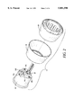
- FIG. 1A shows an external, exploded, view of a typical outside door lock assembly
- FIG. 1B shows an assembly, view of the internal side of an outdoor door lock assembly and also showing one preferred version of the axial retainer in accordance with the invention
- FIG. 2 shows an exploded, perspective, internal view of the multiple parts of a typical outside door lock assembly
- FIG. 3 shows an exploded, partial perspective, interior view of the multiple parts of a typical outside door assembly together with one of the preferred embodiments of the invention for an axial retainer means;
- FIG. 4 shows a perspective view of the axial restraining means in accordance with one preferred embodiment of the invention
- FIG. 5A and 5B show, respectively, an exploded unassembled view of axial retainer in accordance with a second embodiment of the invention, and when it has been assembled;
- FIG. 6 shows a perspective view of an axial retainer, in accordance with a second embodiment of the invention, from the outwardly facing side.
- Outer door lock assembly 14 comprises a cylinder and housing assembly 16, a ring 18 (typically made of a brass finish) and a ring insert 20.
- the parts 16, 18, and 20 are designed for axial nesting, one within the other, along the axis of the bore 12. Parts 16, 18 and 20 are separately manufactured items to be assembled on-site with the installation of a door lock assembly in a door.
- Mounting screws 22 are provided to secure assembly 14 to the outside of door 10 when the installation is completed.
- the separate parts 16, 18, and 20 may be dropped during installation so that the exterior finish of at least one of the parts may be damaged, and the structural shape of several of them may be altered, rendering them unfit for use.
- FIG. 1B shows a view of the interior face of the outer door assembly 14, together with an inner door assembly 24 and the axial restraining means 26 of the invention in its assembled position.
- Mounting screws 22 secure the outer assembly 14 with the inner assembly 24 once the door lock assembly has been installed.
- FIG. 2 there is shown an exploded perspective view showing the interior face of the outer door lock assembly 14. More particularly, cylinder and housing assembly 16 exhibits on its interior face, apertures 16a, 16b, and 16c. Apertures 16a and 16b are preferably threaded to receive mounting screws 22 (see FIG. 1A) so that the outer door lock assembly 14 may be secured to the door.
- Cylinder and housing assembly 16 also has, on its interior side, an aperture 16c which may, or may not, be threaded. The purpose of aperture 16c will become apparent from the ensuing description. Cylinder and housing assembly 16, when assembled, will also have as part thereof a screw 16d, the purpose of which is to axially restrain the lock cylinder, shown partially as 28.
- FIG. 3 shows an exploded, pre-assembled, view of the various parts previously described with reference to FIGS. 1 and 2. More particularly, FIG. 3 shows that the axial retainer 26 has a pin projection 26a designed to be pressed-fitted into aperture 16c when the outer door lock assembly 14 has been collapsed onto itself. Retainer 26 also has a downwardly depending portion 26f to engage a tail 16f of the cylinder and housing assembly 16 to prevent rotation of retainer 26.
- axial retainer 26 shows a pin projection 26a having on the periphery thereof protrusions 26b which are, designed to perform a friction fit when axial restrainer 26 is inserted into aperture 16c (see FIG. 3).
- the retainer 26 has a peripheral outer edge which is stepped, in which the outer most peripheral edge 26c is stepped from the interior edge 26d.
- Retainer 26 also has a beveled cutout 26e so that, the retainer 26 may be removed after it has been inserted into aperture 16c. Beveled edge 26e facilitates the insertion of, for example, a screwdriver, to free the retainer 26 from its inserted position.
- FIGS. 5A and 5B there is shown an alternate preferred embodiment of the invention in which the cylinder and housing assembly 16 has only one vacant bore 16c (in additions to bores 16a and 16b for receiving the mounting screws 22).
- aperture 16c receives the screw 16d and its normal function, absent the invention, is to secure the lock cylinder 28 against axial movement.
- an housing assembly 16 also exhibits a cutout 16e the function of which will be described shortly.
- a retainer plate 30 is interposed between bolt 16d and aperture 16c.
- Plate 30 has an aperture 32athrough which bolt 16d will pass prior to being secured.
- Plate 30 also has a cutout 32b with a ledge 32c (see FIG. 6) designed to fit into aperture 16e of the cylinder and housing assembly 16.
- Tab, or ledge, 32c, when fitted into aperture 16e will prevent plate 30 from rotation about the axis of aperture 16c.
- the screw 16d in addition to serving its normal function of axially restraining the cylinder lock also serves to axially secure the cylinder and lock assembly 16 through the ring 18 by way of retainer plate 30.
- the tab 32c fits into aperture 16e prevent it from rotation about the axis of aperture 16c.
- Retainer 26 and plate 30 may be made of any suitable material, including metals, plastics, or the like.
Abstract
Description
Claims (5)
Priority Applications (1)
| Application Number | Priority Date | Filing Date | Title |
|---|---|---|---|
| US08/754,612 US5881590A (en) | 1996-11-20 | 1996-11-20 | Axial door bolt retainer |
Applications Claiming Priority (1)
| Application Number | Priority Date | Filing Date | Title |
|---|---|---|---|
| US08/754,612 US5881590A (en) | 1996-11-20 | 1996-11-20 | Axial door bolt retainer |
Publications (1)
| Publication Number | Publication Date |
|---|---|
| US5881590A true US5881590A (en) | 1999-03-16 |
Family
ID=25035568
Family Applications (1)
| Application Number | Title | Priority Date | Filing Date |
|---|---|---|---|
| US08/754,612 Expired - Lifetime US5881590A (en) | 1996-11-20 | 1996-11-20 | Axial door bolt retainer |
Country Status (1)
| Country | Link |
|---|---|
| US (1) | US5881590A (en) |
Cited By (8)
| Publication number | Priority date | Publication date | Assignee | Title |
|---|---|---|---|---|
| US6230528B1 (en) * | 1998-09-04 | 2001-05-15 | Tong Lung Metal Industry Co. | Adjustable device for an auxiliary lock |
| US20060131897A1 (en) * | 2004-12-17 | 2006-06-22 | The Steelworks Corporation | Door latch mounting bracket |
| US7219519B1 (en) * | 2005-12-27 | 2007-05-22 | I-Tek Metal Mfg. Co. Ltd | Cylinder housing for auxiliary lock |
| US20080028809A1 (en) * | 2006-08-04 | 2008-02-07 | Ebling Keith J | Deadbolt clip / retainer for interior double cylinder sets |
| US20080121002A1 (en) * | 2006-11-24 | 2008-05-29 | Chia-Min Sun | Deadbolt lock device with a reinforced housing |
| US7596975B1 (en) * | 2006-12-21 | 2009-10-06 | Zhi Man Yuan | Lock mechanism |
| US7967509B2 (en) | 2007-06-15 | 2011-06-28 | S.C. Johnson & Son, Inc. | Pouch with a valve |
| US20220178166A1 (en) * | 2019-08-01 | 2022-06-09 | Taiwan Fu Hsing Industrial Co., Ltd. | Auxiliary lock with reinforcement structure |
Citations (12)
| Publication number | Priority date | Publication date | Assignee | Title |
|---|---|---|---|---|
| US470412A (en) * | 1892-03-08 | James roche | ||
| US1875396A (en) * | 1932-09-06 | sghlage | ||
| US2207898A (en) * | 1938-09-26 | 1940-07-16 | Charles S Schoenecke | Pressure gauge tester |
| US3500670A (en) * | 1967-03-15 | 1970-03-17 | Gen Alarm Corp | Lock mechanism and alarm |
| US3514983A (en) * | 1968-11-01 | 1970-06-02 | Kysor Industrial Corp | Mounting assembly for actuators of cylinder locks |
| US3869890A (en) * | 1973-01-24 | 1975-03-11 | Schlage Lock Co | Screw guide |
| US4073172A (en) * | 1976-06-07 | 1978-02-14 | Schlage Lock Company | High security deadbolt lock |
| US5010749A (en) * | 1990-07-23 | 1991-04-30 | Taiwan Fu Hsing Industry Co., Ltd. | Locking device for an auxiliary lock |
| US5186030A (en) * | 1991-11-25 | 1993-02-16 | Taiwan Fu Hsing Industry Co., Ltd. | Locking device for an auxiliary lock |
| US5216910A (en) * | 1992-09-02 | 1993-06-08 | Lin Jui Chang | Auxiliary lock with an anti-breakage device |
| US5267461A (en) * | 1990-01-05 | 1993-12-07 | Mul-T-Lock Ltd. | Cylinder guard |
| US5551264A (en) * | 1994-09-27 | 1996-09-03 | Tong-Lung Metal Industry Co., Ltd. | Door lock having a deadbolt assembly with a low-cost corrosion-resistant bolt member |
-
1996
- 1996-11-20 US US08/754,612 patent/US5881590A/en not_active Expired - Lifetime
Patent Citations (12)
| Publication number | Priority date | Publication date | Assignee | Title |
|---|---|---|---|---|
| US470412A (en) * | 1892-03-08 | James roche | ||
| US1875396A (en) * | 1932-09-06 | sghlage | ||
| US2207898A (en) * | 1938-09-26 | 1940-07-16 | Charles S Schoenecke | Pressure gauge tester |
| US3500670A (en) * | 1967-03-15 | 1970-03-17 | Gen Alarm Corp | Lock mechanism and alarm |
| US3514983A (en) * | 1968-11-01 | 1970-06-02 | Kysor Industrial Corp | Mounting assembly for actuators of cylinder locks |
| US3869890A (en) * | 1973-01-24 | 1975-03-11 | Schlage Lock Co | Screw guide |
| US4073172A (en) * | 1976-06-07 | 1978-02-14 | Schlage Lock Company | High security deadbolt lock |
| US5267461A (en) * | 1990-01-05 | 1993-12-07 | Mul-T-Lock Ltd. | Cylinder guard |
| US5010749A (en) * | 1990-07-23 | 1991-04-30 | Taiwan Fu Hsing Industry Co., Ltd. | Locking device for an auxiliary lock |
| US5186030A (en) * | 1991-11-25 | 1993-02-16 | Taiwan Fu Hsing Industry Co., Ltd. | Locking device for an auxiliary lock |
| US5216910A (en) * | 1992-09-02 | 1993-06-08 | Lin Jui Chang | Auxiliary lock with an anti-breakage device |
| US5551264A (en) * | 1994-09-27 | 1996-09-03 | Tong-Lung Metal Industry Co., Ltd. | Door lock having a deadbolt assembly with a low-cost corrosion-resistant bolt member |
Cited By (10)
| Publication number | Priority date | Publication date | Assignee | Title |
|---|---|---|---|---|
| US6230528B1 (en) * | 1998-09-04 | 2001-05-15 | Tong Lung Metal Industry Co. | Adjustable device for an auxiliary lock |
| US20060131897A1 (en) * | 2004-12-17 | 2006-06-22 | The Steelworks Corporation | Door latch mounting bracket |
| US7219519B1 (en) * | 2005-12-27 | 2007-05-22 | I-Tek Metal Mfg. Co. Ltd | Cylinder housing for auxiliary lock |
| US20080028809A1 (en) * | 2006-08-04 | 2008-02-07 | Ebling Keith J | Deadbolt clip / retainer for interior double cylinder sets |
| US7389660B2 (en) | 2006-08-04 | 2008-06-24 | Newfrey Llc | Deadbolt clip/retainer for interior double cylinder sets |
| US20080121002A1 (en) * | 2006-11-24 | 2008-05-29 | Chia-Min Sun | Deadbolt lock device with a reinforced housing |
| US7596975B1 (en) * | 2006-12-21 | 2009-10-06 | Zhi Man Yuan | Lock mechanism |
| US7967509B2 (en) | 2007-06-15 | 2011-06-28 | S.C. Johnson & Son, Inc. | Pouch with a valve |
| US20220178166A1 (en) * | 2019-08-01 | 2022-06-09 | Taiwan Fu Hsing Industrial Co., Ltd. | Auxiliary lock with reinforcement structure |
| US11773620B2 (en) * | 2019-08-01 | 2023-10-03 | Taiwan Fu Hsing Industrial Co., Ltd. | Auxiliary lock with reinforcement structure |
Similar Documents
| Publication | Publication Date | Title |
|---|---|---|
| US5732578A (en) | Device for maintaining the horizontality of a door lock lever | |
| US6309158B1 (en) | Adjustable length captive panel fastener | |
| US5881590A (en) | Axial door bolt retainer | |
| US4907771A (en) | Hanger with improved positioning structure | |
| US4305266A (en) | Locking apparatus for portable devices | |
| US4892211A (en) | Ceiling Boxes for ceiling fan support | |
| US6139276A (en) | Ceiling fan assembly and method for assembling same | |
| EP1149219B1 (en) | Staking and mounting pin for a vehicle door latch | |
| US4930822A (en) | Retention plate assembly for retaining a lock | |
| US6488439B1 (en) | Downrod adaptor | |
| US5335525A (en) | Universal adaptor for deadbolt | |
| US4579474A (en) | Joining device | |
| US5111715A (en) | Window motor attachment to vehicle door | |
| US6676178B2 (en) | Door lock assembly having escutcheon with removable posts | |
| US5088154A (en) | Door hinge system | |
| US20040244446A1 (en) | Lid device of double-sided auxilary lock | |
| CA2297788A1 (en) | Device in a light fitting | |
| EP0488697B1 (en) | Improvements relating to shelving | |
| US2967728A (en) | Door handle construction | |
| CA2122093A1 (en) | Door hole cover | |
| US6412319B1 (en) | Lockset having keyed egg-shaped knob | |
| WO1990011667A1 (en) | Speaker mounting arrangement | |
| EP0698165B1 (en) | Improvements in or relating to backplates | |
| AU2004219921A1 (en) | Cylinder housing arrangement | |
| GB2309513A (en) | Mounting of built-in lamp |
Legal Events
| Date | Code | Title | Description |
|---|---|---|---|
| AS | Assignment |
Owner name: SCHLAGE LOCK COMPANY, CALIFORNIA Free format text: ASSIGNMENT OF ASSIGNORS INTEREST;ASSIGNOR:SMALL, STEVEN D.;REEL/FRAME:008317/0669 Effective date: 19961115 |
|
| STCF | Information on status: patent grant |
Free format text: PATENTED CASE |
|
| FEPP | Fee payment procedure |
Free format text: PAYOR NUMBER ASSIGNED (ORIGINAL EVENT CODE: ASPN); ENTITY STATUS OF PATENT OWNER: LARGE ENTITY |
|
| FEPP | Fee payment procedure |
Free format text: PAYOR NUMBER ASSIGNED (ORIGINAL EVENT CODE: ASPN); ENTITY STATUS OF PATENT OWNER: LARGE ENTITY Free format text: PAYER NUMBER DE-ASSIGNED (ORIGINAL EVENT CODE: RMPN); ENTITY STATUS OF PATENT OWNER: LARGE ENTITY |
|
| FPAY | Fee payment |
Year of fee payment: 4 |
|
| REMI | Maintenance fee reminder mailed | ||
| FPAY | Fee payment |
Year of fee payment: 8 |
|
| FPAY | Fee payment |
Year of fee payment: 12 |
|
| AS | Assignment |
Owner name: SCHLAGE LOCK COMPANY LLC, INDIANA Free format text: NUNC PRO TUNC ASSIGNMENT;ASSIGNOR:SCHLAGE LOCK COMPANY;REEL/FRAME:031731/0273 Effective date: 20131126 |
|
| AS | Assignment |
Owner name: JPMORGAN CHASE BANK, N.A., AS ADMINISTRATIVE AGENT Free format text: SECURITY AGREEMENT;ASSIGNOR:SCHLAGE LOCK COMPANY LLC;REEL/FRAME:031831/0091 Effective date: 20131126 |
|
| AS | Assignment |
Owner name: JPMORGAN CHASE BANK, N.A., AS ADMINISTRATIVE AGENT Free format text: SECURITY AGREEMENT;ASSIGNOR:SCHLAGE LOCK COMPANY LLC;REEL/FRAME:034173/0001 Effective date: 20141015 |