US5880727A - Reprographic system for arranging presets locations in a multi-level user interface - Google Patents
Reprographic system for arranging presets locations in a multi-level user interface Download PDFInfo
- Publication number
- US5880727A US5880727A US08/838,106 US83810697A US5880727A US 5880727 A US5880727 A US 5880727A US 83810697 A US83810697 A US 83810697A US 5880727 A US5880727 A US 5880727A
- Authority
- US
- United States
- Prior art keywords
- screen
- activatable
- reduction
- enlargement
- user interface
- Prior art date
- Legal status (The legal status is an assumption and is not a legal conclusion. Google has not performed a legal analysis and makes no representation as to the accuracy of the status listed.)
- Expired - Lifetime
Links
- 230000009467 reduction Effects 0.000 claims abstract description 62
- 238000000034 method Methods 0.000 claims abstract description 10
- 230000006870 function Effects 0.000 claims description 37
- 230000004044 response Effects 0.000 claims description 8
- 238000007639 printing Methods 0.000 description 14
- 108091008695 photoreceptors Proteins 0.000 description 4
- 230000002452 interceptive effect Effects 0.000 description 2
- 238000012986 modification Methods 0.000 description 2
- 230000004048 modification Effects 0.000 description 2
- 230000003213 activating effect Effects 0.000 description 1
- 230000004913 activation Effects 0.000 description 1
- 238000010276 construction Methods 0.000 description 1
- 230000003247 decreasing effect Effects 0.000 description 1
- 238000013461 design Methods 0.000 description 1
- 238000010586 diagram Methods 0.000 description 1
- 238000005516 engineering process Methods 0.000 description 1
- 239000011521 glass Substances 0.000 description 1
- 230000003993 interaction Effects 0.000 description 1
- 238000012423 maintenance Methods 0.000 description 1
- 230000005012 migration Effects 0.000 description 1
- 238000013508 migration Methods 0.000 description 1
- 230000008569 process Effects 0.000 description 1
- 238000012545 processing Methods 0.000 description 1
- 230000000717 retained effect Effects 0.000 description 1
Images


Classifications
-
- H—ELECTRICITY
- H04—ELECTRIC COMMUNICATION TECHNIQUE
- H04N—PICTORIAL COMMUNICATION, e.g. TELEVISION
- H04N1/00—Scanning, transmission or reproduction of documents or the like, e.g. facsimile transmission; Details thereof
- H04N1/0035—User-machine interface; Control console
- H04N1/00405—Output means
- H04N1/00408—Display of information to the user, e.g. menus
-
- G—PHYSICS
- G03—PHOTOGRAPHY; CINEMATOGRAPHY; ANALOGOUS TECHNIQUES USING WAVES OTHER THAN OPTICAL WAVES; ELECTROGRAPHY; HOLOGRAPHY
- G03G—ELECTROGRAPHY; ELECTROPHOTOGRAPHY; MAGNETOGRAPHY
- G03G15/00—Apparatus for electrographic processes using a charge pattern
- G03G15/50—Machine control of apparatus for electrographic processes using a charge pattern, e.g. regulating differents parts of the machine, multimode copiers, microprocessor control
- G03G15/5016—User-machine interface; Display panels; Control console
- G03G15/502—User-machine interface; Display panels; Control console relating to the structure of the control menu, e.g. pop-up menus, help screens
-
- H—ELECTRICITY
- H04—ELECTRIC COMMUNICATION TECHNIQUE
- H04N—PICTORIAL COMMUNICATION, e.g. TELEVISION
- H04N1/00—Scanning, transmission or reproduction of documents or the like, e.g. facsimile transmission; Details thereof
- H04N1/0035—User-machine interface; Control console
- H04N1/00405—Output means
- H04N1/00408—Display of information to the user, e.g. menus
- H04N1/00413—Display of information to the user, e.g. menus using menus, i.e. presenting the user with a plurality of selectable options
- H04N1/00416—Multi-level menus
- H04N1/00419—Arrangements for navigating between pages or parts of the menu
- H04N1/00424—Arrangements for navigating between pages or parts of the menu using a list of graphical elements, e.g. icons or icon bar
-
- H—ELECTRICITY
- H04—ELECTRIC COMMUNICATION TECHNIQUE
- H04N—PICTORIAL COMMUNICATION, e.g. TELEVISION
- H04N1/00—Scanning, transmission or reproduction of documents or the like, e.g. facsimile transmission; Details thereof
- H04N1/0035—User-machine interface; Control console
- H04N1/00405—Output means
- H04N1/00408—Display of information to the user, e.g. menus
- H04N1/00413—Display of information to the user, e.g. menus using menus, i.e. presenting the user with a plurality of selectable options
- H04N1/00416—Multi-level menus
- H04N1/00419—Arrangements for navigating between pages or parts of the menu
- H04N1/00427—Arrangements for navigating between pages or parts of the menu using a menu list
-
- H—ELECTRICITY
- H04—ELECTRIC COMMUNICATION TECHNIQUE
- H04N—PICTORIAL COMMUNICATION, e.g. TELEVISION
- H04N1/00—Scanning, transmission or reproduction of documents or the like, e.g. facsimile transmission; Details thereof
- H04N1/0035—User-machine interface; Control console
- H04N1/00405—Output means
- H04N1/00408—Display of information to the user, e.g. menus
- H04N1/00413—Display of information to the user, e.g. menus using menus, i.e. presenting the user with a plurality of selectable options
- H04N1/00416—Multi-level menus
- H04N1/00419—Arrangements for navigating between pages or parts of the menu
- H04N1/00432—Arrangements for navigating between pages or parts of the menu using tabs
-
- H—ELECTRICITY
- H04—ELECTRIC COMMUNICATION TECHNIQUE
- H04N—PICTORIAL COMMUNICATION, e.g. TELEVISION
- H04N1/00—Scanning, transmission or reproduction of documents or the like, e.g. facsimile transmission; Details thereof
- H04N1/0035—User-machine interface; Control console
- H04N1/00405—Output means
- H04N1/00408—Display of information to the user, e.g. menus
- H04N1/0044—Display of information to the user, e.g. menus for image preview or review, e.g. to help the user position a sheet
-
- H—ELECTRICITY
- H04—ELECTRIC COMMUNICATION TECHNIQUE
- H04N—PICTORIAL COMMUNICATION, e.g. TELEVISION
- H04N1/00—Scanning, transmission or reproduction of documents or the like, e.g. facsimile transmission; Details thereof
- H04N1/0035—User-machine interface; Control console
- H04N1/00405—Output means
- H04N1/00474—Output means outputting a plurality of functional options, e.g. scan, copy or print
-
- H—ELECTRICITY
- H04—ELECTRIC COMMUNICATION TECHNIQUE
- H04N—PICTORIAL COMMUNICATION, e.g. TELEVISION
- H04N1/00—Scanning, transmission or reproduction of documents or the like, e.g. facsimile transmission; Details thereof
- H04N1/0035—User-machine interface; Control console
- H04N1/00405—Output means
- H04N1/00477—Indicating status, e.g. of a job
-
- H—ELECTRICITY
- H04—ELECTRIC COMMUNICATION TECHNIQUE
- H04N—PICTORIAL COMMUNICATION, e.g. TELEVISION
- H04N1/00—Scanning, transmission or reproduction of documents or the like, e.g. facsimile transmission; Details thereof
- H04N1/0035—User-machine interface; Control console
- H04N1/00405—Output means
- H04N1/00482—Output means outputting a plurality of job set-up options, e.g. number of copies, paper size or resolution
-
- H—ELECTRICITY
- H04—ELECTRIC COMMUNICATION TECHNIQUE
- H04N—PICTORIAL COMMUNICATION, e.g. TELEVISION
- H04N1/00—Scanning, transmission or reproduction of documents or the like, e.g. facsimile transmission; Details thereof
- H04N1/0035—User-machine interface; Control console
- H04N1/00501—Tailoring a user interface [UI] to specific requirements
-
- G—PHYSICS
- G06—COMPUTING; CALCULATING OR COUNTING
- G06F—ELECTRIC DIGITAL DATA PROCESSING
- G06F3/00—Input arrangements for transferring data to be processed into a form capable of being handled by the computer; Output arrangements for transferring data from processing unit to output unit, e.g. interface arrangements
- G06F3/12—Digital output to print unit, e.g. line printer, chain printer
- G06F3/1297—Printer code translation, conversion, emulation, compression; Configuration of printer parameters
Definitions
- the present invention is directed to a user interface for a reprographic system. More specifically, the present invention is directed to a user interface which enables the user to select a subset of a set of preset values to be associated with a main copying screen while having the full set of preset values being associated with a particuliar preset setting screen.
- a conventional reprographic system is the office copier.
- the copier in the office equipment context, refers to a light lens xerographic copier in which paper originals are in fact photographed. The images are focused on an area of a photoreceptor, which is subsequently developed with toner. The developed image on the photoreceptor is then transferred to a copy sheet which in turn is used to create a permanent copy of the original.
- a digital copier performs the same functions as a light lens copier, except that the original image to be copied is not directly focused on a photoreceptor. Instead, with a digital copier, the original image is scanned by a device generally known as a raster input scanner (RIS) which is typically in the form of the linear array of small photosensors.
- RIS raster input scanner
- the original image is focused on the photosensors in the RIS.
- the photosensors convert the various light and dark areas of the original image to a set of digital signals. These digital signals are temporarily retained in a memory and then eventually used to operate a digital printing apparatus when it is desired to print copies of the original.
- the digital signals may also be sent directly to the printing device without being stored in a memory.
- the digital printing apparatus can be any known type of printing system responsive to digital data, such as a modulating scanning laser which discharges image wide portions of a photoreceptor, or an ink jet printhead.
- the digital multi-function machine is a single machine which provides a user with more than one function.
- An example of a typical multi-function machine would include a digital facsimile function, a digital printing function, and a digital copy function.
- a user can utilize this digital multi-function machine to send a facsimile of an original document to a remote receiving device, to scan in an original image and print copies thereof, and/or to print documents from either a network source, locally connected source, or from a portable memory device which has been inserted into the multi-function machine.
- FIG. 2 An example of the basic architecture of a digital multi-function machine is illustrated in FIG. 2.
- the architecture of the digital multi-function machine includes a scanner 3 which converts an original image into a set of digital signals that can be either stored or reproduced.
- the scanner 3 is connected to a central bus system 1 which may be either a single bus or a plurality of buses which provide interconnections and intercommunications between the various modules and devices on a multi-function digital machine.
- the digital multi-function machine further includes a digital printing device 23 which converts digital signals representing an image into a hardcopy of that image on a recording medium whether the recording medium be paper, transparency, or other type of markable medium.
- the digital multi-function machine also includes a memory 21 for storing a variety of types of digital information such as machine fault information, machine history information, digital images to be processed at a later time, instruction sets for the machine, job instruction sets, etc.
- a typical digital multi-function machine includes an electronic pre-collation memory section 7 which may store the digital representation of the image being presently rendered by the digital printing device 23.
- the digital image is already laid out in its page structure so that it can be readily rendered by the digital printing device 23.
- the digital multi-function machine as illustrated in FIG. 2, further includes a user interface 5 which allows the user to select the various functions of the multi-function machine, program various job attributes for the particularly selected function, provide other input to the multi-function machine as well as display informational data from the digital multi-function machine.
- the digital multi-function machine would include a network interface 19 and an electronic subsystem (ESS) controller 9 which would control the interrelationship between the various modules or devices on the digital multi-function machine and the network.
- ESS electronic subsystem
- the digital multi-function machine would include, typically, a voice/data modem 11 and a telephone circuit board 13. Moreover, the digital multi-function machine may include input/output drives 17 such as a floppy disc drive, a CD ROM drive, a tape drive, or other type of drive which can accept a portable memory device.
- input/output drives 17 such as a floppy disc drive, a CD ROM drive, a tape drive, or other type of drive which can accept a portable memory device.
- the machine also includes a finisher 29 which can perform certain operations upon the printed output from the printing device 23.
- the digital multi-function machine includes a controller 15 which controls all the functions within the multi-function device so as to coordinate all the interactions between the various modules and devices.
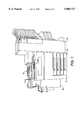
- FIG. 1 illustrates an overall construction of a digital multi-function machine.
- the digital multi-function machine as illustrated in FIG. 1, includes a scanning station 35, a printing station 55, and a user interface 50.
- the digital multi-function machine may also include a finisher device 45 which may be a sorter, tower mailbox, stapler, etc.
- the printing station 55 may include a plurality of paper trays 40 that store the paper used in the printing process.
- the digital multi-function machine may include a high capacity feeder 30 which is capable of holding large amounts of paper stock to be used by the machine.
- This scanning station 30 may be a platen type scanner or may include a constant velocity transport system which moves the original documents across a stationary scanning device. Moreover, the scanning station 30 may also include a document handling system which is capable of placing the original documents, automatically, on the glass platen for scanning.
- the printing station 55 would retrieve the proper paper from one of the multiple paper trays or the high capacity feeder, render the desired image on the retrieved paper, and output the printed image to the finishing device 45 for further operations.
- the user interface 50 allows the user to control the various functions of the digital multi-function machine by presenting various types of screens to the user which provides the user an opportunity to program certain job characteristics or function characteristics.
- the user-programmable features on a reprographic system have improved and increased. More specifically, the early reprographic systems included only a minimal number of user-programmable features, such as reduction, lighter/darker, and number of copies. As the reprographic machines evolved with technology, the user-programmable features became numerous. This increase in the population in the number of user-programmable features causes the user interfaces of the reprographic machine to increase in size, thereby creating new problems when trying to design a compact machine.
- One such user interface is an interactive electronic display user interface which has multiple levels or multiple screens.
- the user of such an interface user can navigate through various screens to select the desired user-programmable features or attributes. More specifically, the user may encounter a main copying screen and navigational buttons to get to other screens or layered screens so as to program different features or attributes associated with those navigational buttons.
- a main copying screen may have a navigational button associated with the feature of reduction/enlargement.
- the user interface would display a screen which has a plurality of reduction/enlargement activatable buttons as well as other programmable areas which allow the user to program a variety of reduction/enlargement values.
- a typical scheme requires a user to navigate through various levels of the screens to program commonly used features or attributes into the reprographic system. Therefore, it is desirable to have a user interface which utilizes the multiple screens and multiple layers of an interactive electronic display user interface, but which has a main copying screen from which a user can readily program a few desired commonly used features without requiring a user to navigate through a plurality of screens.
- One aspect of the present invention is a method for enabling an assignment of a preset feature value from a set of preset feature values for a copy operation to be performed on a reprographic system.
- the method displays a first screen on a user interface associated with the reprographic system, the first screen displaying a plurality of activatable areas corresponding to a subset of the set of preset feature values and an activatable area corresponding to a second screen associated with the set of preset feature values; determines if the activatable area corresponding to the second screen is engaged; and displays the second screen on the user interface associated with the reprographic system when the activatable area corresponding to the second screen is engaged, the second screen displaying a plurality of activatable areas such that each preset feature value within the set of preset feature values has an activatable area associated therewith.
- the system includes a marking system; a scanning system; a user interface; and a controller.
- the user interface displays a first screen, the first screen having a plurality of activatable areas corresponding to a subset of a set of preset feature values and an activatable area corresponding to a second screen associated with preset feature values.
- the controller determines if the activatable area corresponding to the second screen is engaged.
- the user interface displays the second screen in response to engagement of the activatable area corresponding to the second screen, the second screen displaying a plurality of activatable areas such that each preset feature value within the set of preset feature values has an activatable area associated therewith.
- a third aspect of the present invention is a digital scanning system.
- the digital scanning system includes a scanning system; a user interface; and a controller.
- the user interface displays a first screen, the first screen having a plurality of activatable areas corresponding to a subset of a set of preset feature values and an activatable area corresponding to a second screen associated with preset feature values.
- the controller determines if the activatable area corresponding to the second screen is engaged.
- the user interface displays the second screen in response to engagement of the activatable area corresponding to the second screen, the second screen displaying a plurality of activatable areas such that each preset feature value within the set of preset feature values has an activatable area associated therewith.
- FIG. 1 is a graphic representation of a digital reprographic machine
- FIG. 2 is a block diagram illustrating the architecture of a digital reprographic machine
- FIG. 3 is a flowchart illustrating a method of programming reduction/enlargement preset values according to the present invention
- FIG. 4 illustrates a user interface screen layout showing a main copying screen according to the concepts of the present invention
- FIG. 5 is a graphical representation of a user interface screen used for programming normal reduction/enlargement values.
- FIG. 6 is a graphical representation of a user interface screen used for programming anamorphic reduction/enlargement values.
- the present invention is directed to a user interface which has a multitude of screens wherein one of the screens is a main scree.
- the main screen has a plurality of activatable areas corresponding to a subset of a set of preset feature values and an activatable area corresponding to a second screen associated with preset feature values.
- a controller within the reprographic machine determines if the activatable area corresponding to the second screen is engaged.
- the user interface displays the second screen in response to engagement of the activatable area corresponding to the second screen, the second screen displaying a plurality of activatable areas such that each preset feature value within the set of preset feature values has an activatable area associated therewith.
- FIG. 3 illustrates a flowchart demonstrating the concepts of the present invention for programming reduction/enlargement preset values.
- the present invention displays a basic copy function screen with a subset of activatable reduction/enlargement preset areas and an activatable more or other reduction/enlargement area.
- the user interface is a touch-sensitive video display device. An example of such a basic copying function screen is illustrated in FIG. 4.
- the basic copy function screen 50 includes a message area 510, a navigational area 520, and a programmable area 530.
- the digital copier will display various messages for the user informing the user of either the status of the machine or assists the user in programming a particular job.
- the navigational area 520 the user may select any of the activatable tabs 521 in order to bring the features associated with that tab forward onto the screen and allowing the present features to fall behind the activated or engaged tab.
- the navigational area 520 includes navigational buttons 522 which allow the user to navigate to other various screens for carrying out other functions with respect to the reprographic system such as maintenance functions, key operator programming functions, supervisory functions, or diagnostic functions, etc.
- the programmable area 530 of screen 50 includes a plurality of activatable areas wherein each activatable area is associated with a certain value, function, or linked screen.
- activatable area 531 is associated with the preset reduction/enlargement value of 100%.
- activatable area 532 of FIG. 4 is associated with a linked screen, more specifically, the screen as illustrated in FIG. 5.
- the present invention upon engagement or activation of the activatable area 532, the present invention will cause the screen as illustrated in FIG. 5 to replace the screen illustrated in FIG. 4 on the user interface.
- activatable areas on the basic copy function screen 50 of FIG. 4 include reduction/enlargement preset activatable areas 533 and 534 which correspond to the preset reduction value 64% and 78%, respectively.
- Another activatable area with respect to reduction/enlargement on the basic copy function screen 50 is the activatable area 535 which corresponds to an auto-function in that when it is selected or engaged, the reprographic system will automatically size the scanned in image to fit properly upon the output recording medium.
- FIG. 3 illustrates that the present invention determines whether an activatable reduction/enlargement preset area has been engaged at step S2. If an activatable reduction/enlargement preset area is engaged at step S2, namely the activatable areas 531, 532, or 533, step S3 sets the reduction/enlargement value associated with the engaged activatable reduction/enlargement preset area as the reduction/enlargement value to be utilized by the reprographic system On the other hand, if step S4 determines that the activatable more or other reduction/enlargement area (activatable area 532 of FIG. 4) is engaged, step S5 displays a new screen having all the possible reduction/enlargement preset activatable areas displayed thereon, namely FIG. 5.
- a display screen 50 includes a message area 510, a user control area 540, and programmable area 550.
- the user control area 540 allows the user to either cancel the selection of this programming screen, reset the programming within this programming screen, or save the programming associated with this programming screen so as to be utilized by the reprographic system when performing the job being programmed.
- the programmable area 550 of the display screen 50 includes a plurality of activatable reduction/enlargement preset areas 551. Moreover, the programmable area 550 includes a display area 554 which displays the current reduction/enlargement setting. The current reduction/enlargement setting can be either increased or decreased by activatable areas 552 and 553, respectively. Lastly, the programmable area 550 includes activatable areas 556 and 555 wherein activatable area 556 allows the user to program in normal reduction/enlargement values; i.e., the values illustrated in FIG. 5; while activatable area 555 allows the user to program anamorphic reduction/enlargement values through another screen (FIG. 6).
- the present invention causes the screen 50 illustrated in FIG. 6 to replace the screen illustrated in FIG. 5 by the user interface.
- FIG. 6 illustrates a screen 50 which includes a message area 510, a user control area 540, and a programmable area 560.
- the programmable area 560 allows a user to program the reduction/enlargement values of the two dimensions independently of each other through activatable areas 561, 562, 564, and 565. Display areas 563 and 566 indicate to the user the reduction/enlargement value for the two independent dimensions.
- the programmable area 560 includes a graphical display area 567 which conveys to the user, graphically, the reduction/enlargement relationship between the two dimensions.
- the user can select which subset of the reduction/enlargement preset values are displayed on the basic copying function screen as illustrated in FIG. 4. More specifically, in a preferred embodiment of the present invention, the user can select any of the various reduction/enlargement preset values illustrated in FIG. 5 to make up the subset of reduction/enlargement preset values which are activatable from the main copying function screen as illustrated in FIG. 4.
- the user may choose to have the reduction/enlargement values 25% and 200% associated with the activatable areas 533 and 534 of FIG. 4, respectively, instead of the reduction/enlargement preset values of 64% and 78%, respectively.
- the user can configure the user interface such that the basic copying screen displays a subset of the reduction/enlargement preset values which are common for that user so that the user need not navigate through a plurality of screens in order to program a commonly used reduction/enlargement value.
- the present invention has been described in detail above, various modifications can be made without departing from the spirit of the invention.
- the user interface can be a video screen which interacts with a point/click device such as a mouse or a video screen which is light sensitive or magnetically sensitive so as to response to a light pen or magnetic pen.
- the present invention is not limited to reduction/enlargement preset values.
- the concepts of the present invention can be expanded to any programmable feature; such as paper selection, finishing features, image processing features, etc.; so as to allow the user to select the commonly used programmable feature to be displayed on the main copying screen. This enables the user to select these commonly used features without navigating through plurality of screens or levels.
- the present invention provides a user interface configuration which enables a user to select a subset of a set of feature preset values from a main copying screen without requiring the user to navigate through a plurality of screens to set these commonly used feature values.
- the user interface allows the user to navigate to a specific feature screen so as to be able to choose a feature value from the full set of preset values or to program in a particular feature value.
Abstract
Description
Claims (20)
Priority Applications (1)
| Application Number | Priority Date | Filing Date | Title |
|---|---|---|---|
| US08/838,106 US5880727A (en) | 1997-04-15 | 1997-04-15 | Reprographic system for arranging presets locations in a multi-level user interface |
Applications Claiming Priority (1)
| Application Number | Priority Date | Filing Date | Title |
|---|---|---|---|
| US08/838,106 US5880727A (en) | 1997-04-15 | 1997-04-15 | Reprographic system for arranging presets locations in a multi-level user interface |
Publications (1)
| Publication Number | Publication Date |
|---|---|
| US5880727A true US5880727A (en) | 1999-03-09 |
Family
ID=25276277
Family Applications (1)
| Application Number | Title | Priority Date | Filing Date |
|---|---|---|---|
| US08/838,106 Expired - Lifetime US5880727A (en) | 1997-04-15 | 1997-04-15 | Reprographic system for arranging presets locations in a multi-level user interface |
Country Status (1)
| Country | Link |
|---|---|
| US (1) | US5880727A (en) |
Cited By (19)
| Publication number | Priority date | Publication date | Assignee | Title |
|---|---|---|---|---|
| US6226472B1 (en) * | 1998-07-31 | 2001-05-01 | Samsung Electronics Co., Ltd. | Printer and power controlling method therefor |
| US6233414B1 (en) * | 2000-01-27 | 2001-05-15 | Xerox Corporation | Methods and systems for providing capability and status indication of an imaging system |
| US6308023B1 (en) * | 1999-06-22 | 2001-10-23 | Sharp Kabushiki Kaisha | Image apparatus having a multiple number of different functional modes |
| US20020063697A1 (en) * | 2000-11-14 | 2002-05-30 | Fuji Xerox Co., Ltd. | Display device, display method and image forming apparatus |
| US6411787B1 (en) * | 2001-03-06 | 2002-06-25 | Hewlett-Packard Company | Independent description selector apparatus and method |
| US20030052926A1 (en) * | 2001-09-14 | 2003-03-20 | Dunlap Kendra L. | System and method for disguising depth in tree menus |
| US20030174073A1 (en) * | 2002-03-15 | 2003-09-18 | George Koppich | Keypad indicating arrangement including virtual key |
| US20040174556A1 (en) * | 1999-10-25 | 2004-09-09 | Paul Lapstun | Copier |
| US20040216058A1 (en) * | 2003-04-28 | 2004-10-28 | Chavers A. Gregory | Multi-function device having graphical user interface incorporating customizable icons |
| US6859287B1 (en) | 2000-06-07 | 2005-02-22 | Hewlett Packard Development Company, L.P. | Enhanced graphical icon apparatus and method for displaying document placement and orientation |
| US6927871B1 (en) * | 2000-11-25 | 2005-08-09 | Silverbrook Research Pty Ltd | Apparatus for interaction with a network computer system |
| US20050177793A1 (en) * | 1999-06-10 | 2005-08-11 | Kabushiki Kaisha Toshiba | Image processing system |
| US20050210373A1 (en) * | 2004-03-16 | 2005-09-22 | Xerox Corporation | Method and system for displaying annotated information associated with a settable variable value feature |
| US20050225800A1 (en) * | 2000-11-25 | 2005-10-13 | Silverbrook Research Pty Ltd | Apparatus for cooling and storing produce |
| US20110129168A1 (en) * | 1999-05-25 | 2011-06-02 | Silverbrook Research Pty Ltd | Pen-shaped sensing device for sensing surface regions |
| US9491328B2 (en) | 2015-02-28 | 2016-11-08 | Xerox Corporation | System and method for setting output plex format using automatic page detection |
| CN107403059A (en) * | 2016-05-19 | 2017-11-28 | 伟伦公司 | Medical treatment device with enhancing user interface controls |
| US20200034007A1 (en) * | 2018-07-25 | 2020-01-30 | Seiko Epson Corporation | Scanning system, scanning program, and machine learning system |
| CN110780554A (en) * | 2018-07-25 | 2020-02-11 | 精工爱普生株式会社 | Display control device and storage medium |
Citations (6)
| Publication number | Priority date | Publication date | Assignee | Title |
|---|---|---|---|---|
| US5463448A (en) * | 1994-04-19 | 1995-10-31 | Eastman Kodak Company | Reproduction apparatus having multiple ways of entering an information system |
| US5495581A (en) * | 1992-02-25 | 1996-02-27 | Tsai; Irving | Method and apparatus for linking a document with associated reference information using pattern matching |
| US5585891A (en) * | 1995-03-29 | 1996-12-17 | Eastman Kodak Company | Set-up navigation scheme for programming reproduction apparatus |
| US5614993A (en) * | 1995-03-03 | 1997-03-25 | Eastman Kodak Company | System and method for job set up summarizing in reprographic apparatus |
| US5727129A (en) * | 1996-06-04 | 1998-03-10 | International Business Machines Corporation | Network system for profiling and actively facilitating user activities |
| US5760771A (en) * | 1996-07-17 | 1998-06-02 | At & T Corp | System and method for providing structured tours of hypertext files |
-
1997
- 1997-04-15 US US08/838,106 patent/US5880727A/en not_active Expired - Lifetime
Patent Citations (6)
| Publication number | Priority date | Publication date | Assignee | Title |
|---|---|---|---|---|
| US5495581A (en) * | 1992-02-25 | 1996-02-27 | Tsai; Irving | Method and apparatus for linking a document with associated reference information using pattern matching |
| US5463448A (en) * | 1994-04-19 | 1995-10-31 | Eastman Kodak Company | Reproduction apparatus having multiple ways of entering an information system |
| US5614993A (en) * | 1995-03-03 | 1997-03-25 | Eastman Kodak Company | System and method for job set up summarizing in reprographic apparatus |
| US5585891A (en) * | 1995-03-29 | 1996-12-17 | Eastman Kodak Company | Set-up navigation scheme for programming reproduction apparatus |
| US5727129A (en) * | 1996-06-04 | 1998-03-10 | International Business Machines Corporation | Network system for profiling and actively facilitating user activities |
| US5760771A (en) * | 1996-07-17 | 1998-06-02 | At & T Corp | System and method for providing structured tours of hypertext files |
Cited By (38)
| Publication number | Priority date | Publication date | Assignee | Title |
|---|---|---|---|---|
| US6226472B1 (en) * | 1998-07-31 | 2001-05-01 | Samsung Electronics Co., Ltd. | Printer and power controlling method therefor |
| US8295653B2 (en) | 1999-05-25 | 2012-10-23 | Silverbrook Research Pty Ltd | Sensing device for sensing surface regions |
| US8031982B2 (en) | 1999-05-25 | 2011-10-04 | Silverbrook Research Pty Ltd | Pen-shaped sensing device for sensing surface regions |
| US20110129168A1 (en) * | 1999-05-25 | 2011-06-02 | Silverbrook Research Pty Ltd | Pen-shaped sensing device for sensing surface regions |
| US20050177793A1 (en) * | 1999-06-10 | 2005-08-11 | Kabushiki Kaisha Toshiba | Image processing system |
| US6943812B1 (en) * | 1999-06-10 | 2005-09-13 | Kabushiki Kaisha Toshiba | Image processing system |
| US7509583B2 (en) | 1999-06-10 | 2009-03-24 | Kabushiki Kaisha Toshiba | Image processing system |
| US6308023B1 (en) * | 1999-06-22 | 2001-10-23 | Sharp Kabushiki Kaisha | Image apparatus having a multiple number of different functional modes |
| US7110126B1 (en) * | 1999-10-25 | 2006-09-19 | Silverbrook Research Pty Ltd | Method and system for the copying of documents |
| US7986427B2 (en) | 1999-10-25 | 2011-07-26 | Silverbrook Research Pty Ltd | System for copying interactive documents |
| US20040174556A1 (en) * | 1999-10-25 | 2004-09-09 | Paul Lapstun | Copier |
| US20090237703A1 (en) * | 1999-10-25 | 2009-09-24 | Silverbrook Research Pty Ltd | System for copying interactive documents |
| US7557944B2 (en) | 1999-10-25 | 2009-07-07 | Silverbrook Research Pty Ltd | Copier |
| US6233414B1 (en) * | 2000-01-27 | 2001-05-15 | Xerox Corporation | Methods and systems for providing capability and status indication of an imaging system |
| US6859287B1 (en) | 2000-06-07 | 2005-02-22 | Hewlett Packard Development Company, L.P. | Enhanced graphical icon apparatus and method for displaying document placement and orientation |
| US20020063697A1 (en) * | 2000-11-14 | 2002-05-30 | Fuji Xerox Co., Ltd. | Display device, display method and image forming apparatus |
| US7458036B2 (en) * | 2000-11-14 | 2008-11-25 | Fuji Xerox Co., Ltd. | Display device, display method and image forming apparatus |
| US20050225800A1 (en) * | 2000-11-25 | 2005-10-13 | Silverbrook Research Pty Ltd | Apparatus for cooling and storing produce |
| US7515292B2 (en) | 2000-11-25 | 2009-04-07 | Silverbrook Research Pty Ltd | Apparatus for cooling and storing produce |
| US20090091793A1 (en) * | 2000-11-25 | 2009-04-09 | Silverbrook Research Pty Ltd | Printer for produce cooling and storage apparatus |
| US6927871B1 (en) * | 2000-11-25 | 2005-08-09 | Silverbrook Research Pty Ltd | Apparatus for interaction with a network computer system |
| US7916336B2 (en) | 2000-11-25 | 2011-03-29 | Silverbrook Research Pty Ltd | Printer for produce cooling and storage apparatus |
| US6411787B1 (en) * | 2001-03-06 | 2002-06-25 | Hewlett-Packard Company | Independent description selector apparatus and method |
| US20030052926A1 (en) * | 2001-09-14 | 2003-03-20 | Dunlap Kendra L. | System and method for disguising depth in tree menus |
| US20030174073A1 (en) * | 2002-03-15 | 2003-09-18 | George Koppich | Keypad indicating arrangement including virtual key |
| US7170429B2 (en) | 2002-03-15 | 2007-01-30 | Kabushiki Kaisha Toshiba | Keypad indicating arrangement including virtual key |
| US7263661B2 (en) * | 2003-04-28 | 2007-08-28 | Lexmark International, Inc. | Multi-function device having graphical user interface incorporating customizable icons |
| US20040216058A1 (en) * | 2003-04-28 | 2004-10-28 | Chavers A. Gregory | Multi-function device having graphical user interface incorporating customizable icons |
| US20050210373A1 (en) * | 2004-03-16 | 2005-09-22 | Xerox Corporation | Method and system for displaying annotated information associated with a settable variable value feature |
| JP2005269640A (en) * | 2004-03-16 | 2005-09-29 | Xerox Corp | Setting method of variable value function and user interface |
| US8677267B2 (en) * | 2004-03-16 | 2014-03-18 | Xerox Corporation | Method and system for displaying annotated information associated with a settable variable value feature |
| US9491328B2 (en) | 2015-02-28 | 2016-11-08 | Xerox Corporation | System and method for setting output plex format using automatic page detection |
| CN107403059A (en) * | 2016-05-19 | 2017-11-28 | 伟伦公司 | Medical treatment device with enhancing user interface controls |
| US10416865B2 (en) * | 2016-05-19 | 2019-09-17 | Welch Allyn, Inc. | Medical device with enhanced user interface controls |
| US20200034007A1 (en) * | 2018-07-25 | 2020-01-30 | Seiko Epson Corporation | Scanning system, scanning program, and machine learning system |
| CN110780554A (en) * | 2018-07-25 | 2020-02-11 | 精工爱普生株式会社 | Display control device and storage medium |
| US11003319B2 (en) * | 2018-07-25 | 2021-05-11 | Seiko Epson Corporation | Display control device and display control program for displaying user interface for selecting one from selection options |
| US11048382B2 (en) * | 2018-07-25 | 2021-06-29 | Seiko Epson Corporation | Scanning system, scanning program, and machine learning system |
Similar Documents
| Publication | Publication Date | Title |
|---|---|---|
| US5880727A (en) | Reprographic system for arranging presets locations in a multi-level user interface | |
| JP3880282B2 (en) | Input display device | |
| US8228343B2 (en) | Image processing apparatus, computer program product, and preview image displaying method | |
| JP3469079B2 (en) | Image forming device | |
| JP4909398B2 (en) | Printing system, printing system control method, and printing apparatus | |
| EP1251408B1 (en) | Multi-market optimized user interface assembly and a reprographic machine having same | |
| EP1724667B1 (en) | Data processing setting apparatus, data processing setting method, data processing setting program, and computer-readable recording medium comprising the program | |
| JPH11231729A (en) | Guidance information display device | |
| EP1489486A2 (en) | Automatic tab displaying and maximum tab storing user interface and a reprographic machine having same | |
| US6690382B1 (en) | Display device capable of color display used in operation mode setting of image formation apparatus | |
| JP3546003B2 (en) | Input display device and input display method | |
| JP2005269640A (en) | Setting method of variable value function and user interface | |
| EP0917006A2 (en) | Input/output model for multifunction user interfaces | |
| EP0873001A2 (en) | User interface for a reprographic system for indicating non-default status of programmable features | |
| JP3689617B2 (en) | Image forming system, control method therefor, and storage medium | |
| JP3761306B2 (en) | Display input operation device | |
| US9491328B2 (en) | System and method for setting output plex format using automatic page detection | |
| US20060013610A1 (en) | Machine user interface including a pop up menu feature | |
| US6999189B2 (en) | Work station having a reduction/enlargement fine tuning feature | |
| US7319534B2 (en) | Image forming apparatus capable of outputting a confirmation copy of at least one individually selected sheet of a plurality of sheets of a copy to be made, and method corresponding thereto | |
| US20060013609A1 (en) | Machine user interface including a selected service details content well | |
| JP2001222190A (en) | Image forming system and its control method, image forming device and data processing method and storage medium | |
| JP3129484B2 (en) | Office equipment display | |
| US20060055665A1 (en) | User interface having button delineating control panel | |
| JPH11143301A (en) | Image forming device |
Legal Events
| Date | Code | Title | Description |
|---|---|---|---|
| AS | Assignment |
Owner name: XEROX CORPORATION, CONNECTICUT Free format text: ASSIGNMENT OF ASSIGNORS INTEREST;ASSIGNORS:BARRETT, MICHAEL W.;MARTIN, ANDREW T.;EMERSON, WILLIAM C.;AND OTHERS;REEL/FRAME:008573/0981 Effective date: 19970611 |
|
| STCF | Information on status: patent grant |
Free format text: PATENTED CASE |
|
| AS | Assignment |
Owner name: BANK ONE, NA, AS ADMINISTRATIVE AGENT, ILLINOIS Free format text: SECURITY INTEREST;ASSIGNOR:XEROX CORPORATION;REEL/FRAME:013153/0001 Effective date: 20020621 |
|
| FPAY | Fee payment |
Year of fee payment: 4 |
|
| AS | Assignment |
Owner name: JPMORGAN CHASE BANK, AS COLLATERAL AGENT, TEXAS Free format text: SECURITY AGREEMENT;ASSIGNOR:XEROX CORPORATION;REEL/FRAME:015134/0476 Effective date: 20030625 Owner name: JPMORGAN CHASE BANK, AS COLLATERAL AGENT,TEXAS Free format text: SECURITY AGREEMENT;ASSIGNOR:XEROX CORPORATION;REEL/FRAME:015134/0476 Effective date: 20030625 |
|
| FPAY | Fee payment |
Year of fee payment: 8 |
|
| FPAY | Fee payment |
Year of fee payment: 12 |
|
| AS | Assignment |
Owner name: XEROX CORPORATION, CONNECTICUT Free format text: RELEASE BY SECURED PARTY;ASSIGNOR:JPMORGAN CHASE BANK, N.A. AS SUCCESSOR-IN-INTEREST ADMINISTRATIVE AGENT AND COLLATERAL AGENT TO JPMORGAN CHASE BANK;REEL/FRAME:066728/0193 Effective date: 20220822 |