US5864517A - Pulsed combustion acoustic wave generator - Google Patents
Pulsed combustion acoustic wave generator Download PDFInfo
- Publication number
- US5864517A US5864517A US08/820,882 US82088297A US5864517A US 5864517 A US5864517 A US 5864517A US 82088297 A US82088297 A US 82088297A US 5864517 A US5864517 A US 5864517A
- Authority
- US
- United States
- Prior art keywords
- fuel
- barrel
- oxidant
- generator
- pressure
- Prior art date
- Legal status (The legal status is an assumption and is not a legal conclusion. Google has not performed a legal analysis and makes no representation as to the accuracy of the status listed.)
- Expired - Fee Related
Links
Images


Classifications
-
- F—MECHANICAL ENGINEERING; LIGHTING; HEATING; WEAPONS; BLASTING
- F23—COMBUSTION APPARATUS; COMBUSTION PROCESSES
- F23C—METHODS OR APPARATUS FOR COMBUSTION USING FLUID FUEL OR SOLID FUEL SUSPENDED IN A CARRIER GAS OR AIR
- F23C15/00—Apparatus in which combustion takes place in pulses influenced by acoustic resonance in a gas mass
-
- F—MECHANICAL ENGINEERING; LIGHTING; HEATING; WEAPONS; BLASTING
- F41—WEAPONS
- F41H—ARMOUR; ARMOURED TURRETS; ARMOURED OR ARMED VEHICLES; MEANS OF ATTACK OR DEFENCE, e.g. CAMOUFLAGE, IN GENERAL
- F41H13/00—Means of attack or defence not otherwise provided for
- F41H13/0043—Directed energy weapons, i.e. devices that direct a beam of high energy content toward a target for incapacitating or destroying the target
- F41H13/0081—Directed energy weapons, i.e. devices that direct a beam of high energy content toward a target for incapacitating or destroying the target the high-energy beam being acoustic, e.g. sonic, infrasonic or ultrasonic
-
- G—PHYSICS
- G01—MEASURING; TESTING
- G01V—GEOPHYSICS; GRAVITATIONAL MEASUREMENTS; DETECTING MASSES OR OBJECTS; TAGS
- G01V1/00—Seismology; Seismic or acoustic prospecting or detecting
- G01V1/02—Generating seismic energy
- G01V1/104—Generating seismic energy using explosive charges
- G01V1/116—Generating seismic energy using explosive charges where pressurised combustion gases escape from the generator in a pulsating manner, e.g. for generating bursts
-
- G—PHYSICS
- G10—MUSICAL INSTRUMENTS; ACOUSTICS
- G10K—SOUND-PRODUCING DEVICES; METHODS OR DEVICES FOR PROTECTING AGAINST, OR FOR DAMPING, NOISE OR OTHER ACOUSTIC WAVES IN GENERAL; ACOUSTICS NOT OTHERWISE PROVIDED FOR
- G10K15/00—Acoustics not otherwise provided for
- G10K15/04—Sound-producing devices
- G10K15/043—Sound-producing devices producing shock waves
Definitions
- the subject invention pertains to a compact device designed to generate repetitive high amplitude acoustic pulses or pressure waves which may be utilized in a variety of applications.
- a device to produce high amplitude impulsive pressure waves may be based on several different schemes. Electrical energy may be utilized to produce sound waves through loudspeakers or piezoelectric devices, but high power requirements may result in energy storage difficulties as well as problems with the large physical dimensions necessary to produce high acoustic intensities (low power densities). Mechanical devices may be used to produce repetitive loud sounds, but would be inefficient and unwieldy. Methods which convert chemical energy to acoustical energy are ideal because of the high power densities which may be achieved. Solid explosives have very high energy densities and are capable of producing extremely high peak pressure levels (i.e., blast waves from bombs), but are dangerous to work with and are not practical to use if a repetitive impulse is required.
- Gaseous and liquid chemicals can be easily stored, are typically quite safe when fuels and oxidizers are separately stored, and can be mixed and combusted in a very rapid manner. Although not as high in energy density as solid explosives, gaseous or liquid combustible mixtures provide reasonable energy densities which may be quickly converted to pressure or acoustical energy. Repetitive release of stored chemical energy (via an energetic chemical reaction) to produce high amplitude pressure/acoustic waves can be achieved through pulsed combustion technology. Pulse combustion includes two different modes of burning: detonation and deflagration.
- Detonative combustion is characterized by an extremely fast flame speed (2,000 to 4,000 m/s) and very high amplitude pressure waves, while deflagrative combustion typically exhibits a much slower flame speed (generally less than about 200 m/s) and significantly lower amplitude pressure waves.
- Sensations of feeling or tickle commence at approximately 130 dB (0.009 psi rms) while significant discomfort occurs at approximately 120 dB (0.003 psi rms). Thus a pressure rise as small as 0.003 psi may cause considerable discomfort.
- Non-continuous tone may have different effects on an individual, especially if the impulses are unexpected.
- An impulsive noise is one which has a high peak pressure acting over a short duration.
- the form of the impulses can be high amplitude sound waves suddenly switched on which then rapidly decay in amplitude or discrete pressure pulses which may contain many frequencies.
- TTS temporary threshold shift
- the amount of TTS increases approximately linearly with exposure time, resulting in an increase in TTS with the total number of repetitive pulses one is exposed to (not the total exposure time).
- the threshold shift immediately begins a rapid recovery and reaches a minimum after approximately 1 minute, but then rebounds to a maximum at approximately 2 min. This is known as the bounce effect and may be useful in attempts at incapacitation/impairment using repetitive impulsive noise.
- non-impulsive noise The threshold of pain normally associated with continuous exposure (non-impulsive noise) cannot be used to predict the risk of damage due to non-continuous sounds (impulsive noise). In fact intermittent noise has been observed to be less hazardous than steady-state noise for an equivalent amount of sound energy delivered to the ear.
- Eye and hand coordination are particularly affected by impulsive noise, with significant impairment lasting from a typical 2 to 3 seconds to as much as 30 seconds in some individuals.
- Peak impulse pressures of a few pounds per square inch can rupture the eardrum with smaller pressures capable of permanently damaging the conducting mechanisms of the inner ear.
- the ear's greatest mechanical sensitivity lies in the 1,500 to 3,000 Hz range, and thus is particularly vulnerable to short-duration blast waves which may contain many such frequencies at significant amplitudes.
- Non-lethal effects of high level impulsive pressure waves include the potential ability to physically move or knock down an individual at close range due to the over-pressure associated with an impulse of sufficient strength.
- Non-auditory damage occurs at impulse peak pressures of approximately 1 atm (14.7 psi) with little physical damage occurring for peak pressures less than 1 atm which last for very short periods of time (milliseconds).
- Infrasound (sound frequencies below approximately 16 Hz) may also have a non-lethal effect on the human body. Pulse jets may cause nausea and difficulty breathing due to the large amplitude impulsive waves generated by the devices, which pulse at up to 45 times per second.
- a pulsed combustion acoustic wave generator which includes a tubular barrel having an inlet end and an open outlet end, a fuel controller for metering a controlled quantity of fuel into the inlet end of the barrel, an oxidant controller for metering a controlled quantity of oxidant into the inlet end of the barrel and an igniter extending into the inlet end of the barrel that is controllable by an operator to ignite a mixture of fuel and oxidant in the inlet end.
- the pulsed combustion acoustic wave generator of the present invention is based on pulse detonation and pulse jet technology which enables the production of strong acoustic impulses. These impulses are adjustable in peak pressure levels and repetition rates to suit different applications regarding the non-lethal incapacitation, impairment, or immobilization of individuals and material targets, crowd control and dispersal, and self defense capability.
- the present invention can be adjusted in size and operation to provide different levels of acoustic power which can quickly be changed.
- the acoustic energy may be directed to some degree, thereby enhancing effectiveness.
- the general configuration of the invention consists of a combustion tube of a predetermined length and diameter.
- One end of the combustor tube is open to allow the blast/shock wave produced by the combustion to propagate into the atmosphere.
- a nozzle or device capable of directing the acoustic energy may be attached to the end of the combustion tube.
- a fuel injection and ignition system meters and ignites the fuel/oxidizer mixture. Variation of the amount of fuel/oxidizer injected into the combustion tube allows adjustment of the impulse peak pressure. The rate at which the fuel/oxidizer is ignited by the ignition system determines the repetition rate.
- a detonation wave is initiated at the closed end of the tube to start the cycle.
- the wave propagates at a high velocity (2,000 to 4,000 m/s) through the fuel/oxidizer mixture, producing very high pressures due to the rapid combustion.
- the detonation wave reaches the open end of the tube, it produces a blast wave of high amplitude.
- the process of filling the tube with a detonable fuel/oxidizer mixture and then producing a detonation can be repeated in a rapid manner (i.e., "pulsed") to produce a series of acoustic pressure waves.
- the frequency of the impulses is controlled by the frequency of injection of the fuel/oxidizer mixture. Ignition is typically initiated by a spark device.
- the invention utilizes pulse jets which operate by deflagrative combustion in which the combustion wave travels at a much slower speed (typically 10 to 100 m/s), thereby producing a much smaller pressure rise compared to pulse detonation.
- the invention includes a tube with a set of reed valves (one-way valves) at one end, while being open at the other end. Operation is achieved by partially filling the tube with a combustible fuel/air mixture near the valved end, with the balance of the tube containing air drawn in from the open end. The combustion of the fuel/air mixture produces a moderate pressure wave which propels the combustion products and remaining air in the tube out of the open end.
- the pressure in the tube drops slightly below ambient due to over expansion of the flow which then allows air to be drawn in through the one-way valves at the closed end and through the open end.
- Fuel is injected into the fresh air in the tube and the cycle is repeated.
- the repetition rate is controlled by the frequency of fuel injection and ignition can be self sustaining once initiated with a spark device.
- a single large amplitude pressure wave or a series of such waves may be useful depend on the intended effect.
- a repeated series of moderate, amplitude (110 to 130 dB peak level) impulsive sounds from the present invention with a significant low frequency content may be quite effective and non-lethal; especially at close ranges where other methods, such as rubber bullets or water cannons can be quite dangerous.
- the potential large low frequency content of an impulsive wave may be difficult to attenuate effectively with typical ear protection devices.
- the present invention discharged at close range may be enough to momentarily confuse, distract, deafen (temporary threshold shift), or startle (temporary loss of eye and hand coordination) the individual or group, resulting in reduced resistance to capture.
- the incapacitating effects of high amplitude impulsive noise are enhanced if the device is discharged in an enclosed space due to the reflections of energy from walls and internal objects. This may make the present invention suitable to military and law enforcement officials who wish to utilize the device for surprise raids on large numbers of people in enclosed spaces (i.e., homes used for drug trafficking and manufacture, etc.).
- the present invention may be used to shatter windshields and vehicle side windows using the potentially high pressure resulting from a reflected high amplitude impulsive wave.
- No high-speed projectiles would be utilized, thereby reducing the possibility of accidental death due to high-speed projectile wounds (gunshot wounds).
- the occupants may also be incapacitated to some degree.
- the present invention may be suited to rapid destruction of windows, doors, and other similar structures which need to be opened quickly without causing serious injury to occupants due to projectiles.
- An advantage that the subject invention has over other techniques such as concussion grenades is the directive nature of the impulse, which may enhance the effects of the blast while reducing the effect on the operator.
- rapid, multiple pressure impulses may be utilized, if necessary; a characteristic not found in concussion grenades and other solid explosive-based devices.
- the amplitude of the impulse generated by the present invention would also be repeatable due to the ability to meter the amount of combustible gas injected into the combustion tube.
- the characteristic size of the device of the subject invention may be selected for the intended purpose. Larger, more powerful devices applicable for crowd control situations could be mounted on a vehicle or structure. More mobile devices of less power could be man-portable to allow for more flexible use. Small devices for personal protection designed for discharges at very close range may even be made semi-concealed.
- the present invention could, with appropriate design, be made to transition to a lethal mode by introducing projectile(s) into the combustion tube just prior to igniting the combustible mixture.
- the resulting high velocity of the combustion products upon expansion from the open end of the combustor tube would effectively propel a projectile(s) to a significant velocity.
- the subject invention could be used to startle, intimidate, and disperse a crowd of people. It could be hand carried or mounted on a building, barricade, or vehicle. Acoustic emissions could be scaled over a large range. As a result, the device could be used at a low setting to gain the attention of an unruly group, at a moderate setting to startle and disorient a crowd, or at fall power to clear an area by making the noise level intolerable. Alternately, the present invention could be designed to operate at a single setting, substantially decreasing the possibility of mistaken use of excessive power.
- the subject invention would be ideal for defense of a fixed position or barricade against a crowd armed only with typical riot weapons (stones, sticks, etc.) Without injuring people, the device would startle them with the abruptness and force of noise, stunning and disorienting them, and forcing their attention away from their objective and toward personal preservation.
- the open end could be inserted into a room through a window or partly open door without exposing the operators to the occupants of the room. After a quick single or multiple pulse burst from the device, the room could be stormed while the occupants are recovering from the effects. This type of situation is also applicable to law-enforcement actions.
- the present invention can be employed as a booby-trap, where a proximity sensor or other type of trigger begins operation without the direct control of an operator.
- the highly directional acoustic emissions would deliver full force effects on the target without undesirable effects on appropriately placed friendly troops.
- the subject invention would be similar to a non-lethal Claymore mine.
- the subject invention has the potential to be used as a non-lethal mine.
- a buried device would, upon being triggered, fire its blast upwards at the target. While a very large device could inflict mortal injury in this manner, a small one almost certainly would not. It would stun and disorient the target, as well as giving loud notice to all concerned that the mine had been triggered.
- the present invention could also be designed to create a fuel-oxidizer cloud above ground before detonating, resulting in a much larger, omni-directional blast (similar to a fuel-air explosive). This type of free explosion could affect targets some distance away.
- the subject invention produces high amplitude pressure waves which propagate through the air in an expanding shock wave.
- these pressure waves could be used to exert pressure force at a distance to, for example, break windows, knock down doors, and other types of use where a non-projectile force needs to be delivered without seriously harming the occupants.
- Multiple units could be synchronized to produce constructively interfering pressure waves, resulting in traveling force loci or nodes with higher pressures than could be achieved with a single device.
- Recent use of loud music for psychological warfare in Panama and Waco, Tex. demonstrates the potential of using acoustics for disrupting sleep, disturbing thought patterns, and causing disorientation.
- the present invention would be ideal for this role, as its acoustic power and speed of pulsing could be varied drastically depending on need, it could run in repeating mode indefinitely as long as fuel is available, and its impulsive noise is very difficult to shut out.
- a device could be set to steadily increase noise levels with a random time between pulses until the target of its emissions surrenders or leaves. Steady-state high frequency noise could be reduced and canceled through electronic means, but high amplitude low frequency transient noise cannot be effectively attenuated in this manner.
- sound suppressers i.e. headphones, earplugs
- the subject invention could be designed to propagate its pulsed acoustic emissions into water where the wave will travel very quickly for long distances.
- the ability to generate, repetitive high amplitude underwater acoustic pulses at any rate desired could be useful for decoys or to drown out noises which could otherwise be detected and identified, such as submarines or surface ships.
- Another important application in this area is that of civilian or military rescues where a device could produce discrete, high amplitude underwater acoustic waves which could be detected at large distances, thereby aiding in location in maritime emergencies.
- the present invention may be capable of setting off contact and pressure triggered underwater mines in the same manner as land mines.
- High amplitude sound waves like those created by this invention, propagate very well under water. As the waves strike the mine surface and reflect, sharp impulses would be delivered to the triggering mechanism.
- the present invention may trigger the mine without the use of conventional explosives which could mask the explosion and are dangerous to carry and place near the mine.
- This invention can function as an acoustic cleaner in power generation facilities. Deposits on the interior heat-transfer and structural surfaces can decrease the efficiency of a heat exchanger and increase the rate of corrosion. By producing low frequency, high amplitude acoustic waves, the subject invention would cause particulate and slag deposits to resonate and dislodge from the surface without having to resort to expensive steam cleaning.
- the subject invention could be used in much the same manner for animal control purposes as it could for crowd control.
- a fixed or mobile unit could be used to scare wildlife or birds away from an airport runway and units suspended from helicopters could be used to herd wild animals without resorting to gunfire.
- the invention's ability to generate precise high amplitude pressure waves in air could be utilized to create these waves in any gas, liquid, or solid material at exact intervals and at significant amplitudes. This ability translates to an inexpensive and precise acoustic emitter for use in acoustic research such as mechanical and electronic noise attenuation and shock wave propagation.
- FIG. 1a is a schematic illustration of a typical deflagrative combustion cycle in a tube
- FIG. 1b is a graph illustrating pressure level variance with time during the combustion cycle of FIG. 1a;
- FIGS. 1c-1e are successive schematic illustrations of a detonative combustion cycle in a tube, each with a graph showing pressure change with time for the portion of the combustion cycle illustrated;
- FIG. 1f is a graph of pressure level versus time illustrating the change in pressure during the detonative combustion cycle illustrated in FIGS. 1c-1e;
- FIG. 2a is a schematic diagram of a pulse combustion acoustic wave generator in accordance with the present invention, intended for use by a single person;
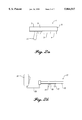
- FIG. 2b is a schematic diagram of a pulse combustion acoustic wave generator of the present invention, intended for use by multiple persons;
- FIG. 3 is a block diagram showing the interconnection between the power system, spark ignition system, control system and fuel/oxidizer metering valves of the pulsed combustion acoustic wave generator of the present invention
- FIG. 4 is a schematic view showing a fuel/oxygen embodiment of the pulsed combustion acoustic wave generator of the present invention
- FIG. 5 is a schematic view showing a fuel/air embodiment of the pulsed combustion acoustic wave generator of the present invention
- FIG. 6 is a schematic view of an air entrained nozzle embodiment of the combustion acoustic wave generator of the present invention.
- FIG. 7 is a graphical representation of exemplary sound pressure versus time data taken from the closed end of the combustor tube for a representative combustion of the pulsed combustion acoustic wave generator of the present invention
- FIG. 8 is a graphical representation of exemplary sound pressure versus time data taken from the open end of the combustor tube for a representative combustion of the pulsed combustion acoustic wave generator of the present invention
- FIG. 9 is a graphical representation of exemplary sound pressure versus fuel/oxidizer equivalence ratio for combustion of representative fuels used with the pulsed combustion acoustic wave generator of the present invention.
- FIG. 10 is a graphical representation of exemplary sound pressure versus amount of combustible mixture for a representative combustion of the pulsed combustion acoustic wave portion of the present invention.
- FIG. 11 is a graphical representative of exemplary sound pressure versus displacement from tube centerline for combustion of representative fuels used with the pulsed combustion acoustic wave generator of the present invention.
- FIGS. 1a and 1b show typical deflagrative combustion cycles and detonative combustion cycles, respectively, and the attendant pressure characteristics which the present invention is capable of producing.
- FIG. 1c shows one possible embodiment of a close-range hand-held pulsed combustion acoustic wave generator 1 with limited firing duration.
- the configuration shown is similar to an oversize flare gun, and would be sized for use in special operations, security, and personal defense applications.
- gaseous, liquid or solid fuel and gaseous or solid oxygen storage is in fuel/oxidizer container 4 beneath the barrel 3, alongside power system 5 (e.g., a battery).
- power system 7 and the spark system 9 are contained behind the barrel 3 above the grip 11.
- Use of advanced, lightweight materials such as, for example, synthetic polymers, would minimize the weight, thereby allowing a high degree of portability.
- the pulsed combustion acoustic wave generator 1 of FIG. 1c is capable of repetitive firing about, for example, 25 rounds without refill, and is about 10 inches in barrel 3 with an inside diameter of barrel 3 being about 1 inch.
- FIG. 2 shows one possible embodiment of a man-portable pulsed combination acoustic wave generator 13 having short- to medium-range and capable of about, for example, 100 shots without refill.
- the combustor tube 15 is equipped with grips 17 and a firing trigger 19, while the spark, control, fuel/oxidizer and power systems are contained in the backpack 21.
- Fuel and electrical cables 23 connect the combustor tube 15 to the backpack 21. Combined weight of the combustor tube 15, and backpack 21 is estimated to be at or below 40 lbs.
- a pulsed acoustic generator 13 having a combustor tube 15 of about 48 inches in length, and an inside diameter of about 4 inches, for example, and having about 300 shots could be used for defense of a fixed position or be mounted to a light vehicle for mobile use.
- This embodiment is large enough to be used against windows and doors, and is likely to require a two person crew to transport.
- One person would carry the combustor tube 15 and any supports (bipod) while the other would carry the spark, control, fuel/oxidizer, and power systems in backpack 21.
- This embodiment could also be mounted on a Jeep or light truck for fast deployment.
- An advantage of the mounted configuration is that the pulsed acoustic wave generator 13 could utilize the vehicle's electrical system and fuel supply, reducing the cost and complexity of the system.
- pulsed acoustic wave generator 13 having a combustor tube 15 length of about 96 inches, an inside diameter of about 12 inches and having about 100 shots is contemplated.
- This embodiment could be used to defend a checkpoint or embassy against vehicles and personnel.
- a possible checkpoint configuration is a subterranean installation directed up at a vehicle.
- the pulsed acoustic wave generator 13 could be mounted parallel to the ground to direct the effects at the vehicle driver.
- this embodiment would be capable of projecting impulsive pressure waves much farther than the smaller scale devices. It also would require substantially more fuel and oxidizer than the smaller examples.
- This embodiment could be mounted on an outpost building and used to prevent approach of hostile personnel, or deployed on an armored vehicle and used to clear a wide path through opposing forces. While not fatal to human targets, this embodiment should cause significant discomfort and disorientation to anyone trying to approach or failing to get out of the way of its passage. As the operating device came nearer, the target would learn that closer proximity would only result in an increase in discomfort and possible permanent damage.
- Non-circular cross section combustor tubes have attractive characteristics from a packaging standpoint, and there is much latitude available in designing these shapes.
- two, three, or more tubes are a simple extension of the design.
- Multiple tubes have important effects on impulsive waveform and amplitude. For example, multiple tubes can fire simultaneously to increase the peak sound pressure level, fire out of phase to increase the effective cycle rate, or ripple-fire to increase the effective duration of the waveform. The use of multiple tubes gives additional flexibility to operation.
- the control system 7 consists of a dedicated microprocessor, which samples the control inputs (desired sound intensity and shot duration, for example), accesses the pre-programmed memory to determine the optimum operating characteristics for the given settings, then manipulates relays or transistors to operate the fuel/oxidizer metering valves and spark ignition system, both described in further detail below. It is estimated that approximately 5 watts of power are required for operation of the control system.
- fuel/oxidizer metering valves 25 may be, for example, solenoid valves that utilize an electrical supply at between 12 and 50 volts DC. Each valve 25 draws a maximum of about 30 watts of electrical power when open. No more than two valves 25 will be in operation at any given time for a portable pulsed combustion acoustic wave generator 1 or 13. Larger embodiments may use more valves 25, but will likely have access to a fixed power supply. In total, the fuel/oxidizer metering valves 25 are estimated to require about 60 watts of power during firing of the pulsed combustion acoustic wave generator 1 or 13.
- the spark ignition system 9, of FIG. 3 supplies spark energy to initiate each detonation.
- the average power requirement for the spark system is approximately 107 watts.
- this power is only required during actual firing while a spark ignition system 9 is shown. It is understood that other types of ignition systems such as laser, chemical, or plasma ignition systems, for example, can be employed.
- Table 2 summarizes the power requirements under nine different conditions of pulsed combustion acoustic wave generator 1 or 13: “Off,” “Standby,” and “Firing.”
- “Off” implies that the system is powered down for storage or carriage.
- control system 7 When switched to “Standby,” control system 7 would be initialized, which would check overall device readiness.
- pulsed combustion acoustic wave generator 1 or 13 can be fired simply by pulling trigger 19.
- the pulsed combustion acoustic wave generator 1 or 13 operator would switch to "Standby” when preparing to fire.
- the "firing" mode is when pulsed combustion acoustic wave generator 1 or 13 is in the process of generating impulsive pressure waves (firing).
- This mode has the highest power consumption, but should have the shortest elapsed time of the three modes during a typical confrontation. For example, the operator may have the device in Standby mode for an hour during a riot, but may only fire for a few seconds of that time. It should be noted that the electrical power requirements during firing depend only on the cycle rate; variation of other combustion parameters have no impact.
- TMF batteries Thin metal film (TMF) batteries, currently commercially available, have a high discharge rate capability and rapid recharge characteristics.
- the two volt TMF battery is a 1.2 amp-hour battery (capable of sustaining 1.2 amps for one hour at 2 volts).
- TMF batteries By using TMF batteries, the necessary power can be provided without excessive weight and size.
- a battery pack consisting of six of these batteries, for instance, would weigh just over one pound, and take up less than ten cubic inches of volume. This battery pack is estimated to be capable of supplying the power requirements for two hours in "Standby" mode in addition to about two minutes firing. Longer operation can be obtained by increasing the size of the battery pack or by use of multiple packs.
- TMF batteries can be rapidly recharged if needed, and are capable of a complete recharge in five to ten minutes. Alternately, the battery pack can be designed to be quickly replaced when the batteries are completely discharged.
- FIGS. 4 and 5 show fuel containers 4 as cylinders for storage of compressed gas for the fuels and oxidizers needed for pulsed combustion acoustic wave generator 1 or 13 operation.
- Quick-disconnect connections would enable the operator to change storage cylinders 4 quickly when the pressure drops too low.
- a handful of small cylinders for a hand-held or man-portable device could be easily carried in a backpack or on a utility belt.
- solid oxygen generators known in the art are attractive.
- the generator grain would be surrounded with insulation, so even if the grain were ignited accidentally, the container would not be hot enough to cause burns. Also, if the generator were set off by a bullet, the oxygen being generated would simply vent without building up dangerous pressure levels. The spent cartridge could be saved for reloading or simply discarded.
- solid fuel generators known in the art are currently being developed by various commercial entities) have very similar attractive features.
- the solid oxygen generator could be packaged in a small insulated cartridge with enough grain for as many shots as desired.
- One feasible configuration would have a battery pack, oxygen supply, and fuel storage combined into a single package.
- the power and fuel supply can be proportioned so that battery, fuel, and oxygen need replacement at the same time. Ejecting the spent cartridge and inserting a new one would complete the re-fueling and re-powering process.
- FIG. 4 shows an embodiment of the present invention, wherein fuel and O 2 as the oxidizer are employed
- FIG. 5 shows an embodiment where fuel and air as the oxidizer are employed to provide energy for detonation.
- the pulsed combustion acoustic wave generator 1 is first readied for operation by the user initiating the "Standby" mode of control system 7 of FIG. 3 which configures power system 5, spark ignition system 9, and fuel/oxidizer metering valves 25 for operation.
- the user initiates the "fire" mode of control system 7 by, for example, actuating trigger 19 of FIG.
- control system 7 opens fuel/oxidizer metering valves 25 a predetermined amount to allow a predetermined amount of fuel and air or O 2 to flow from fuel, air, and oxygen containers 4a, 4b, 4c, and 4d into combustor tube 15.
- Control system 7 then actuates spark ignition system 9, located adjacent to inlet end 26 of combustor tube 15 to provide a spark within combustor tube 15, which initiates combustion and the propagation of a sound wave through combustor tube 15 and out of open outlet end 27 of combustor tube 15.
- High amplitude pressure waves are produced as described above using detonative combustion when the combustion wave travels down combustor tube 15 faster than the speed of sound (supersonic).
- the combustion-generated pressure rise in combustor tube 15 does not have time to exhaust to the atmosphere before combustion is complete.
- the elevated pressure in combustor tube 15 does not begin to decrease until the detonation wave has passed out of the open outlet end 27 of combustor tube 15 and the high amplitude sound pressure wave has begun to travel away from pulsed combustion acoustic wave generator 1 or 13.
- the flame front travels much more slowly (subsonically), and the pressure waves run ahead of the combustion front.
- Modification of the fuel to oxidizer ratio affects the waveform peak amplitude, combustion wave speed, and other aspects of the waveform. This parameter is most likely to be beneficial for ⁇ tuning ⁇ the waveform to a desired shape and amplitude.
- Reducing the amount of fuel and oxidizer has the following effect.
- a detonation wave is initiated and travels down the combustor tubes 15 as usual.
- combustion no longer supports the pressure wave propagation, so the wave speed begins to decrease and the waveform starts to change as the wave propagates through the rest of the combustor tube 15.
- the wave slows down, its amplitude decreases.
- Filling combustion tube 15 with progressively smaller and smaller amounts of fuel and oxidizer will progressively decrease the amplitude of the pressure wave at the open end 27. The result is a reduction in the level of non-lethal effects and/or a reduction in range for the same level of effects.
- the operator may wish to gain the attention of a noisy crowd. Reducing the amount of fuel will reduce the noise level and ⁇ sharpness ⁇ of the waveform so that the crowd is not subjected to the full power setting.
- An alternate scenario involves a target which is at closer range than appropriate for full power. Reduction in acoustic power can deliver the appropriate level of non-lethal effects without permanently harming the target. Modulating the amount of combustible mixture is performed by control system 7.
- Pulsed combustion wave generator 1 or 13 creates an impulsive pressure wave each time combustor tube 15 is filled with combustible mixture and ignited.
- Control system 7 can be designed to control the rate at which this cycle is repeated. Example settings may range from one cycle per second to startle an opponent, to several tens of cycles per second to induce various less than lethal effects. A single or quick burst of low amplitude pulses is probably the most effective at gaining attention. A long continuous series of high amplitude pulses would be appropriate for disorientation and stun effects, or defense of a fixed position.
- the rate at which the pulses are generated may change the type or severity of the non-lethal effects.
- FIGS. 4 and 5 show open end 27 with a flared tip 29.
- a focusing or de-focusing of the acoustic wave may be effected by variation of the geometry of the open end.
- air entrainment ring 31 adjacent open end 27 of combustor tube 15 creates a sheath of cold air around and flowing with the hot exhaust from the tube.
- the fuel mixture combustor tube 15 detonates. the hot, high pressure combustion products rush out of open end 27 at very high speed.
- cool air is drawn into ring 31 through opening 33 spacing ring 31 from open end 27 through the action of viscosity and pressure differential.
- the cool air surrounds the hot exhaust and accelerates toward the hot exhaust velocity.
- air entrainment 31 operates in a similar fashion to bypass ducting on a modem turbofan engine. In addition to increasing the efficiency of the engine, bypass air lowers the off-axis noise generated by the engine.
- the entrained air contains the acoustic pulses and lowers the acoustic noise off the device axis.
- the speed of sound in the cool air is substantially lower than it is in the hot exhaust, so the, cylindrical contact boundary between the two flows acts as a pressure reflection surface.
- the hot exhaust is decelerated by the process of accelerating the cool air. Overall the average flow velocity is lower, but the combined mass is substantially higher, resulting in an increase in flow momentum. This momentum may aid the propagation of the impulsive wave and increase the force exerted on a target.
- the air that is entrained into the device is taken from the region through which a pressure wave must travel to affect the operator of the device. The resulting air velocity in this region should slow down and increase the rate of decay of any pressure wave traveling toward the operator.
- Measurements from the pressure history at the closed end of the combustor tube give an approximate indication of the impulse which is delivered to the operator or the structure supporting the combustor tube.
- FIG. 7, for example, shows an example of a closed end pressure history from a 2-inch ID ⁇ 36-inch-long combustor. Comparison of these data to mass and velocity data from conventional projectile weapons indicates that the present invention of the indicated size produces approximately one-third the impulse generated by an M16 rifle (based on a 55 grain projectile with a muzzle velocity of about 3,094 ft/sec).
- FIG. 8 shows an example pressure history at the open end of the combustor tube. These data are used to determine the impulsive waveform as the pressure wave exits the combustor. As FIG. 8 shows, the peak pressures measured are quite high--nearly 250 psig in this case. By varying the fuel used and other test parameters, the peak pressure can be changed dramatically based on the desired acoustic output.
- the amplitude of the acoustic wave produced by the present invention can be tailored by variation of key operational variables such as fuel/oxidizer stoichiometry, partial filling of the combustor, and appropriate fuel/oxidizer selection.
- FIG. 9 illustrates the effect of changing the fuel/oxidizer stoichiometry (the ratio of fuel to oxidizer in the combustible mixture) on the peak sound pressure level at a given distance from the device.
- the highest SPLs are obtained by use of fuel/oxidizer mixtures with a stoichiometry near unity.
- the SPL can be decreased by operating with a stoichiometry other than unity.
- the peak SPL decreases as the percentage of the combustor tube filled with the fuel/oxidizer mixture decreases. This effect is illustrated in FIG. 10.
- FIG. 11 illustrates the reduction of peak SPL away from the combustor tube axis.
- the device may utilize a wide range of fuel types which include hydrogen, lower hydrocarbons (methane, ethylene, propane, ethane, butane, etc.), and higher hydrocarbons which include automotive (kerosene, diesel, etc.) and aviation fuels (Jet A, JP-1, etc.) in pure form or in a mixture (with other fuels i.e., natural gas, MAPP gas, etc.).
- fuels can be stored in solid, liquid or compressed gas form and injected as a gas, liquid, or solid.
- Solid fuel sources which upon decomposition in an oxidizer-poor environment produce a fuel rich effluent which can be injected into the combustor along with the selected oxidizer.
- Other solid fuels sources could include fine metal or organic powders.
- Liquid fuels can be injected directly as a liquid (kerosene, Jet-A, etc.) or can be vaporized (atmospheric propane or heated liquid hydrocarbon). Gaseous fuels can be stored via compressed gas cylinders and offer the advantage of a pre-pressurized fueling system.
- oxidizers include air and oxygen.
- Fuel/oxygen mixtures generally result in higher energy densities and require significantly lower ignition energies relative to fuel/air mixtures. In general, for a given fuel, a fuel/oxygen mixture will enable the use of a smaller combustor diameter than a fuel/air mixture due to the physics of detonative wave propagation.
- Air and oxygen can be stored in compressed form or, in the case of air, can be inducted directly from the atmosphere. Oxygen and air could be stored in liquid form. Solid storage of oxygen can be achieved by use of commercially available gas generators which contain a grain composed of sodium chlorate or lithium perchlorate. Decomposition of this grain produces an oxygen rich effluent.
- the wide range of fuel/oxidizer combinations which can be used by the present invention enable a high degree of flexibility for use in different applications.
Landscapes
- Engineering & Computer Science (AREA)
- Physics & Mathematics (AREA)
- Remote Sensing (AREA)
- Acoustics & Sound (AREA)
- Life Sciences & Earth Sciences (AREA)
- General Engineering & Computer Science (AREA)
- Chemical & Material Sciences (AREA)
- Combustion & Propulsion (AREA)
- Radar, Positioning & Navigation (AREA)
- Environmental & Geological Engineering (AREA)
- Geology (AREA)
- General Life Sciences & Earth Sciences (AREA)
- General Physics & Mathematics (AREA)
- Geophysics (AREA)
- Mechanical Engineering (AREA)
- Multimedia (AREA)
- Catching Or Destruction (AREA)
Abstract
Description
              TABLE 1
______________________________________
Examples of typical sound pressure levels (SPLs) and sound
pressures for common environments.
Sound    Sound Pressure
Pressure Level dB
Pa(N/m.sup.2)
         (2 × 10.sup.-5 Pa ref.)
                         Typical Environment
______________________________________
0.000020 0               Threshold of Hearing
0.000063 10              Rustle of Leaves
0.00020  20              Broadcast Studio
0.00063  30              Bedroom at Night
0.0020   40              Library
0.0063   50              Quiet Office
0.02     60              Conversational Speech
0.063    70              Average Radio
0.1      74              Light Traffic Noise
0.2      80              Typical Factory
0.63     90              Subway Train
2.0      100             Symphony Orchestra
6.3      110             Rock Band
20.      120             Aircraft Takeoff
200      140             Threshold of pain
______________________________________
              TABLE 2
______________________________________
Total Estimated Power Requirements
            Mode:
            Off     Standby Firing
______________________________________
Control System
              0 Watts   5 Watts  5 Watts
Metering Valves
              0 Watts   0 Watts 60 Watts
Spark Ignition System
              0 Watts   0 Watts 107 Watts
Total         0 Watts   5 Watts 172 Watts
______________________________________
Claims (19)
Priority Applications (1)
| Application Number | Priority Date | Filing Date | Title |
|---|---|---|---|
| US08/820,882 US5864517A (en) | 1997-03-21 | 1997-03-21 | Pulsed combustion acoustic wave generator |
Applications Claiming Priority (1)
| Application Number | Priority Date | Filing Date | Title |
|---|---|---|---|
| US08/820,882 US5864517A (en) | 1997-03-21 | 1997-03-21 | Pulsed combustion acoustic wave generator |
Publications (1)
| Publication Number | Publication Date |
|---|---|
| US5864517A true US5864517A (en) | 1999-01-26 |
Family
ID=25231960
Family Applications (1)
| Application Number | Title | Priority Date | Filing Date |
|---|---|---|---|
| US08/820,882 Expired - Fee Related US5864517A (en) | 1997-03-21 | 1997-03-21 | Pulsed combustion acoustic wave generator |
Country Status (1)
| Country | Link |
|---|---|
| US (1) | US5864517A (en) |
Cited By (54)
| Publication number | Priority date | Publication date | Assignee | Title |
|---|---|---|---|---|
| US6324956B1 (en) * | 2000-02-23 | 2001-12-04 | Apti, Inc. | Method and apparatus for neutralization of mines and obstacles |
| US6341518B1 (en) | 1999-12-10 | 2002-01-29 | U.E Systems, Inc. | Ultrasonic standard |
| US6349538B1 (en) | 2000-06-13 | 2002-02-26 | Lockheed Martin Corporation | Annular liquid fueled pulse detonation engine |
| US6408614B1 (en) * | 1997-03-11 | 2002-06-25 | Dornier Medizintechnik Gmbh | High-power pressure wave source |
| US6477829B1 (en) | 2000-05-09 | 2002-11-12 | Lockheed Martin Corporation | Combined cycle pulse combustion/gas turbine engine |
| US20020185330A1 (en) * | 2001-04-19 | 2002-12-12 | Schlumberger Technology Corporation | Method and apparatus for generating seismic waves |
| WO2003032012A1 (en) * | 2001-10-05 | 2003-04-17 | Bae Systems (Land And Sea Systems) Limited | Underwater sound source |
| US6705075B1 (en) | 2000-06-05 | 2004-03-16 | Alliant Techsystems Inc. | Digital solid rocket motor and gas generator |
| US20040059319A1 (en) * | 2002-07-26 | 2004-03-25 | Dornier Medtech Systems Gmbh | System and method for a lithotripter |
| US20040123583A1 (en) * | 2002-12-30 | 2004-07-01 | United Technologies Corporation | Combustion ignition |
| JP2004361075A (en) * | 2003-05-30 | 2004-12-24 | General Electric Co <Ge> | Detonation damper for pulse detonation engine |
| US20050010140A1 (en) * | 2001-11-29 | 2005-01-13 | Dornier Medtech Systems Gmbh | Shockwave or pressure-wave type therapeutic apparatus |
| US20050112516A1 (en) * | 2003-11-20 | 2005-05-26 | Aarnio Michael J. | Detonative cleaning apparatus |
| US20050126595A1 (en) * | 2003-12-11 | 2005-06-16 | Flatness Scott A. | Detonative cleaning apparatus |
| US20050150714A1 (en) * | 2003-08-26 | 2005-07-14 | Michael Raleigh | Non-explosive acoustic source |
| US20060005786A1 (en) * | 2004-06-14 | 2006-01-12 | Habib Tony F | Detonation / deflagration sootblower |
| US20060112672A1 (en) * | 2004-11-25 | 2006-06-01 | Razzell Anthony G | Combustor |
| US20070055157A1 (en) * | 2005-08-05 | 2007-03-08 | Dornier Medtech Systems Gmbh | Shock wave therapy device with image production |
| WO2007142536A1 (en) * | 2006-06-02 | 2007-12-13 | Mike Eggers Limited | Noise generating device to scare birds or trigger avalanches |
| US20080002395A1 (en) * | 2006-06-30 | 2008-01-03 | Todd Eisenberg | Incapacitating high intensity incoherent light beam |
| WO2008051298A2 (en) | 2006-04-17 | 2008-05-02 | Soundblast Technologies, Llc | A system and method for generating and directing very loud sounds |
| US20080239876A1 (en) * | 2006-09-18 | 2008-10-02 | American Technology Corporation | High intensity vehicle proximity acoustics |
| US20080267927A1 (en) * | 2004-12-15 | 2008-10-30 | Dornier Medtech Systems Gmbh | Methods for improving cell therapy and tissue regeneration in patients with cardiovascular diseases by means of shockwaves |
| US20080277194A1 (en) * | 2007-05-11 | 2008-11-13 | Lockheed Martin Corporation | Engine and technique for generating an acoustic signal |
| JP2009198036A (en) * | 2008-02-20 | 2009-09-03 | Hiroshima Univ | Pulse combustion device and pulse combustion method |
| US20090320439A1 (en) * | 2006-01-31 | 2009-12-31 | General Electric Company | Pulsed detonation combustor cleaning device and method of operation |
| US20100025449A1 (en) * | 2008-08-01 | 2010-02-04 | International Business Machines Corporation | Method and apparatus for remotely activating destruction of a glass window |
| US20100109342A1 (en) * | 2008-11-03 | 2010-05-06 | Vladislav Oleynik | Electrical power generator |
| US20100154699A1 (en) * | 2008-12-19 | 2010-06-24 | Woodscan Industries, Inc. | Air Powered Signaling System |
| WO2010103321A1 (en) * | 2009-03-13 | 2010-09-16 | Matthew Henry | Acoustic apparatus and method of operation |
| US20100286574A1 (en) * | 2006-01-17 | 2010-11-11 | Dornier Medtech Systems Gmbh | Treating apparatus |
| US20100294894A1 (en) * | 2007-05-08 | 2010-11-25 | John Choate | Sonic boom overpressure to minimize uncontrolled movement, to prevent smuggling and for border or site location control |
| US20110000389A1 (en) * | 2006-04-17 | 2011-01-06 | Soundblast Technologies LLC. | System and method for generating and directing very loud sounds |
| US20110101703A1 (en) * | 2009-11-03 | 2011-05-05 | Causwave, Inc. | Multiphase material generator vehicle |
| US20110235465A1 (en) * | 2010-03-25 | 2011-09-29 | Raytheon Company | Pressure and frequency modulated non-lethal acoustic weapon |
| US20110235467A1 (en) * | 2010-03-25 | 2011-09-29 | Raytheon Company | Man-portable non-lethal pressure shield |
| US20110261645A1 (en) * | 2010-04-26 | 2011-10-27 | David Allen Sager | Non Explosive Process and Device for Triggering an Avalanche |
| US8091336B2 (en) | 2000-12-14 | 2012-01-10 | Pratt & Whitney Rocketdyne, Inc. | Method to initiate multiple chamber detonation wave combustors |
| US8181561B2 (en) * | 2008-06-02 | 2012-05-22 | Causwave, Inc. | Explosive decompression propulsion system |
| US8302730B2 (en) | 2006-04-17 | 2012-11-06 | Soundblast Technologies, Llc | System and method for generating and controlling conducted acoustic waves for geophysical exploration |
| US20130291784A1 (en) * | 2012-05-01 | 2013-11-07 | Curtis E. Graber | Directional isophasic toroidal whistle |
| WO2013175404A2 (en) * | 2012-05-22 | 2013-11-28 | David Cohen | Methods devices apparatus assemblies and systems for generating & directing sound pressure waves |
| WO2014056485A1 (en) * | 2012-10-11 | 2014-04-17 | Anton Grassl | Compressed gas generator |
| US8721105B2 (en) | 2006-06-30 | 2014-05-13 | Genesis Illumination, Inc. | Incapacitating high intensity incoherent light beam |
| US20140305877A1 (en) * | 2013-04-11 | 2014-10-16 | Sanuwave, Inc. | Apparatuses and methods for generating shock waves for use in the energy industry |
| US8905186B2 (en) | 2006-04-17 | 2014-12-09 | Soundblast Technologies, Llc | System for coupling an overpressure wave to a target media |
| US20150234061A1 (en) * | 2006-04-17 | 2015-08-20 | Soundblast Technologies, Llc | System and Method for Harnessing Pressure Produced by a Detonation |
| US9217392B2 (en) | 2011-12-12 | 2015-12-22 | Curtis E. Graber | Vortex cannon with enhanced ring vortex generation |
| US9581704B2 (en) | 2015-01-22 | 2017-02-28 | Soundblast Technologies, Llc | System and method for accelerating a mass using a pressure produced by a detonation |
| RU2671801C2 (en) * | 2017-03-29 | 2018-11-06 | Акционерное общество "Московский радиотехнический институт Российской академии наук" (АО "МРТИ РАН") | Method for active protection areas shock-wave action on underwater object |
| RU2696048C2 (en) * | 2017-11-21 | 2019-07-30 | Российская Федерация, от имени которой выступает ФОНД ПЕРСПЕКТИВНЫХ ИССЛЕДОВАНИЙ | Method for active protection of water area by impact-wave action on underwater object and device for its implementation |
| WO2019185736A1 (en) | 2018-03-29 | 2019-10-03 | Explo Engineering Ag | Device and method for producing pressure waves of high amplitude |
| RU2774772C2 (en) * | 2018-03-29 | 2022-06-22 | Экспло Инжиниринг Аг | Apparatus and method for generating high-amplitude pressure waves |
| US11701632B2 (en) | 2018-12-10 | 2023-07-18 | Ekona Power Inc. | Method and reactor for producing one or more products |
Citations (9)
| Publication number | Priority date | Publication date | Assignee | Title |
|---|---|---|---|---|
| US2766837A (en) * | 1951-11-05 | 1956-10-16 | Mccollum Burton | Seismic exploration apparatus |
| US2831666A (en) * | 1956-10-19 | 1958-04-22 | Jack K Compton | Mixing device |
| US3048816A (en) * | 1955-10-28 | 1962-08-07 | Harold A Lubnow | Low frequency underwater sound generation |
| US3064753A (en) * | 1959-02-09 | 1962-11-20 | Socony Mobil Oil Co Inc | Repetitive seismic wave source |
| US3064619A (en) * | 1960-03-11 | 1962-11-20 | Gen Precision Inc | Acoustic generator and shock wave radiator |
| US4189026A (en) * | 1954-01-13 | 1980-02-19 | The United States Of America As Represented By The Secretary Of The Navy | Underwater generation of low frequency sound |
| US4642611A (en) * | 1983-10-14 | 1987-02-10 | Koerner Andre F | Sound engine |
| US4896502A (en) * | 1985-09-17 | 1990-01-30 | Aerospatiale Societe Nationale Industrielle | Ramjet engine equipped with a plurality of carburated air supply nozzles and a missile equipped with such a ramjet engine |
| US5345758A (en) * | 1993-04-14 | 1994-09-13 | Adroit Systems, Inc. | Rotary valve multiple combustor pulse detonation engine |
-
1997
- 1997-03-21 US US08/820,882 patent/US5864517A/en not_active Expired - Fee Related
Patent Citations (10)
| Publication number | Priority date | Publication date | Assignee | Title |
|---|---|---|---|---|
| US2766837A (en) * | 1951-11-05 | 1956-10-16 | Mccollum Burton | Seismic exploration apparatus |
| US4189026A (en) * | 1954-01-13 | 1980-02-19 | The United States Of America As Represented By The Secretary Of The Navy | Underwater generation of low frequency sound |
| US3048816A (en) * | 1955-10-28 | 1962-08-07 | Harold A Lubnow | Low frequency underwater sound generation |
| US2831666A (en) * | 1956-10-19 | 1958-04-22 | Jack K Compton | Mixing device |
| US3064753A (en) * | 1959-02-09 | 1962-11-20 | Socony Mobil Oil Co Inc | Repetitive seismic wave source |
| US3064619A (en) * | 1960-03-11 | 1962-11-20 | Gen Precision Inc | Acoustic generator and shock wave radiator |
| US4642611A (en) * | 1983-10-14 | 1987-02-10 | Koerner Andre F | Sound engine |
| US4896502A (en) * | 1985-09-17 | 1990-01-30 | Aerospatiale Societe Nationale Industrielle | Ramjet engine equipped with a plurality of carburated air supply nozzles and a missile equipped with such a ramjet engine |
| US5345758A (en) * | 1993-04-14 | 1994-09-13 | Adroit Systems, Inc. | Rotary valve multiple combustor pulse detonation engine |
| US5353588A (en) * | 1993-04-14 | 1994-10-11 | Adroit Systems, Inc. | Rotary valve multiple combustor pulse detonation engine |
Non-Patent Citations (19)
| Title |
|---|
| Bernstein, A., Heiser, W., and Hevenor, C., "Compound-Compressible Nozzle Flow," AIAA Paper 66-663, 1966. |
| Bernstein, A., Heiser, W., and Hevenor, C., Compound Compressible Nozzle Flow, AIAA Paper 66 663, 1966. * |
| Clark, L.T., "Aplication of Compound Flow Analysis to Supersonic Ejector-Mixer Performance Prediction," AIAA Paper 95-0645, 1995. |
| Clark, L.T., Aplication of Compound Flow Analysis to Supersonic Ejector Mixer Performance Prediction, AIAA Paper 95 0645, 1995. * |
| FOA, J.V., "Intermittant Jets", vol. XII High Speed Aerodynamics and Jet Propulsion, 1959. |
| FOA, J.V., Intermittant Jets , vol. XII High Speed Aerodynamics and Jet Propulsion, 1959. * |
| Heiser, W.H. "Thrust Augmentation." Paper No. 66-GT-116, American Society of Mechanical Engineers. 1966. |
| Heiser, W.H. Thrust Augmentation. Paper No. 66 GT 116, American Society of Mechanical Engineers. 1966. * |
| Johnson, W., Analytical and Experimental Study of the Pulsejet Ejector, Ph.D. Dissertation, Department of Mechanical Engineering, University of Clemson, 1967. * |
| Lockwood, R.M. "Interim Summary Report on Investigation of the Process of Energy Transfer from an Intermittent Jet to a Secondary Fluid in an Ejector-type Thrust Augmentor." Hiller Aircraft Corp. Report No. ARD-286, Mar. 31, 1961. |
| Lockwood, R.M. "Interim Summary Report on Investigation of the Process of Energy Transfer from an Intermittent Jet to a Secondary Fluid in an Ejector-type Thrust Augmentor." Hiller Aircraft Corp. Report No. ARD-305, Jun. 30, 1962. |
| Lockwood, R.M. Interim Summary Report on Investigation of the Process of Energy Transfer from an Intermittent Jet to a Secondary Fluid in an Ejector type Thrust Augmentor. Hiller Aircraft Corp. Report No. ARD 286, Mar. 31, 1961. * |
| Lockwood, R.M. Interim Summary Report on Investigation of the Process of Energy Transfer from an Intermittent Jet to a Secondary Fluid in an Ejector type Thrust Augmentor. Hiller Aircraft Corp. Report No. ARD 305, Jun. 30, 1962. * |
| Mattingly, J.D., Heiser, W.H., and Daley, D.H., Aircraft Engine Design, AIAA Education Series, AIAA, Washington, DC, 1987. * |
| O Brien, J.G. The Pulse Jet Engine A Review of Its Development Potential , Naval Postgraduate School, Jun. 1974. * |
| Oates, G.C., Editor, Aircraft Propulsion Systems Technology and Design, AIAA Education Series, AIAA, Washington, DC, 1989. * |
| O'Brien, J.G. "The Pulse Jet Engine A Review of Its Development Potential", Naval Postgraduate School, Jun. 1974. |
| Sutton, G.P., "Rocket Propulsion Elements: An Introduction to the Engineering of Rockets," Wiley-Interscience Publications, New York, New York, 1992. |
| Sutton, G.P., Rocket Propulsion Elements: An Introduction to the Engineering of Rockets, Wiley Interscience Publications, New York, New York, 1992. * |
Cited By (107)
| Publication number | Priority date | Publication date | Assignee | Title |
|---|---|---|---|---|
| US6408614B1 (en) * | 1997-03-11 | 2002-06-25 | Dornier Medizintechnik Gmbh | High-power pressure wave source |
| US6341518B1 (en) | 1999-12-10 | 2002-01-29 | U.E Systems, Inc. | Ultrasonic standard |
| US6606932B2 (en) | 2000-02-23 | 2003-08-19 | Apti, Inc. | Method and apparatus for neutralization of mines and obstacles |
| US6324956B1 (en) * | 2000-02-23 | 2001-12-04 | Apti, Inc. | Method and apparatus for neutralization of mines and obstacles |
| US6477829B1 (en) | 2000-05-09 | 2002-11-12 | Lockheed Martin Corporation | Combined cycle pulse combustion/gas turbine engine |
| US6705075B1 (en) | 2000-06-05 | 2004-03-16 | Alliant Techsystems Inc. | Digital solid rocket motor and gas generator |
| US6349538B1 (en) | 2000-06-13 | 2002-02-26 | Lockheed Martin Corporation | Annular liquid fueled pulse detonation engine |
| US8091336B2 (en) | 2000-12-14 | 2012-01-10 | Pratt & Whitney Rocketdyne, Inc. | Method to initiate multiple chamber detonation wave combustors |
| US20020185330A1 (en) * | 2001-04-19 | 2002-12-12 | Schlumberger Technology Corporation | Method and apparatus for generating seismic waves |
| US6776256B2 (en) * | 2001-04-19 | 2004-08-17 | Schlumberger Technology Corporation | Method and apparatus for generating seismic waves |
| WO2003032012A1 (en) * | 2001-10-05 | 2003-04-17 | Bae Systems (Land And Sea Systems) Limited | Underwater sound source |
| US20050010140A1 (en) * | 2001-11-29 | 2005-01-13 | Dornier Medtech Systems Gmbh | Shockwave or pressure-wave type therapeutic apparatus |
| US20040059319A1 (en) * | 2002-07-26 | 2004-03-25 | Dornier Medtech Systems Gmbh | System and method for a lithotripter |
| US7785276B2 (en) | 2002-07-26 | 2010-08-31 | Dornier Medtech Systems Gmbh | System and method for a lithotripter |
| US7047724B2 (en) * | 2002-12-30 | 2006-05-23 | United Technologies Corporation | Combustion ignition |
| US20040123583A1 (en) * | 2002-12-30 | 2004-07-01 | United Technologies Corporation | Combustion ignition |
| JP2004361075A (en) * | 2003-05-30 | 2004-12-24 | General Electric Co <Ge> | Detonation damper for pulse detonation engine |
| JP4569951B2 (en) * | 2003-05-30 | 2010-10-27 | ゼネラル・エレクトリック・カンパニイ | Pulse detonation engine detonation damper |
| US7055308B2 (en) | 2003-05-30 | 2006-06-06 | General Electric Company | Detonation damper for pulse detonation engines |
| US20050150714A1 (en) * | 2003-08-26 | 2005-07-14 | Michael Raleigh | Non-explosive acoustic source |
| US7028807B2 (en) * | 2003-08-26 | 2006-04-18 | Bae Systems Advanced Technologies, Inc. | Non-explosive acoustic source |
| US20050112516A1 (en) * | 2003-11-20 | 2005-05-26 | Aarnio Michael J. | Detonative cleaning apparatus |
| US7011047B2 (en) * | 2003-11-20 | 2006-03-14 | United Technologies Corporation | Detonative cleaning apparatus |
| US20080092828A1 (en) * | 2003-12-11 | 2008-04-24 | United Technologies Corporation | Detonative cleaning apparatus |
| US20050126595A1 (en) * | 2003-12-11 | 2005-06-16 | Flatness Scott A. | Detonative cleaning apparatus |
| US20060005786A1 (en) * | 2004-06-14 | 2006-01-12 | Habib Tony F | Detonation / deflagration sootblower |
| US7360508B2 (en) | 2004-06-14 | 2008-04-22 | Diamond Power International, Inc. | Detonation / deflagration sootblower |
| US7637096B2 (en) * | 2004-11-25 | 2009-12-29 | Rolls-Royce Plc | Pulse jet engine having pressure sensor means for controlling fuel delivery into a combustion chamber |
| US20060112672A1 (en) * | 2004-11-25 | 2006-06-01 | Razzell Anthony G | Combustor |
| US9060915B2 (en) | 2004-12-15 | 2015-06-23 | Dornier MedTech Systems, GmbH | Methods for improving cell therapy and tissue regeneration in patients with cardiovascular diseases by means of shockwaves |
| US20080267927A1 (en) * | 2004-12-15 | 2008-10-30 | Dornier Medtech Systems Gmbh | Methods for improving cell therapy and tissue regeneration in patients with cardiovascular diseases by means of shockwaves |
| US7988631B2 (en) | 2005-08-05 | 2011-08-02 | Dornier Medtech Systems Gmbh | Shock wave therapy device with image production |
| US20070055157A1 (en) * | 2005-08-05 | 2007-03-08 | Dornier Medtech Systems Gmbh | Shock wave therapy device with image production |
| US20100286574A1 (en) * | 2006-01-17 | 2010-11-11 | Dornier Medtech Systems Gmbh | Treating apparatus |
| US20090320439A1 (en) * | 2006-01-31 | 2009-12-31 | General Electric Company | Pulsed detonation combustor cleaning device and method of operation |
| US20110000389A1 (en) * | 2006-04-17 | 2011-01-06 | Soundblast Technologies LLC. | System and method for generating and directing very loud sounds |
| US8172034B2 (en) * | 2006-04-17 | 2012-05-08 | Soundblast Technologies Llc | System and method for generating and directing very loud sounds |
| EP2008121A2 (en) * | 2006-04-17 | 2008-12-31 | Soundblast Technologies, LLC | System and method for generating and controlling conducted acoustic waves for geophysical exploration |
| WO2008051298A2 (en) | 2006-04-17 | 2008-05-02 | Soundblast Technologies, Llc | A system and method for generating and directing very loud sounds |
| US20110192307A1 (en) * | 2006-04-17 | 2011-08-11 | Soundblast Technologies Llc | System and method for ignition of a gaseous or dispersed fuel-oxidant mixture |
| US9268048B2 (en) * | 2006-04-17 | 2016-02-23 | Soundblast Technologies, Llc | System and method for harnessing pressure produced by a detonation |
| US7882926B2 (en) * | 2006-04-17 | 2011-02-08 | Soundblast Technologies, Llc | System and method for generating and directing very loud sounds |
| WO2008051297A3 (en) * | 2006-04-17 | 2008-11-20 | Soundblast Technologies Llc | A system and method for ignition of a gaseous or dispersive fuel-oxidant mixture |
| WO2008051298A3 (en) * | 2006-04-17 | 2008-11-20 | Soundblast Technologies Llc | A system and method for generating and directing very loud sounds |
| US20150234061A1 (en) * | 2006-04-17 | 2015-08-20 | Soundblast Technologies, Llc | System and Method for Harnessing Pressure Produced by a Detonation |
| EP2008026A4 (en) * | 2006-04-17 | 2012-02-15 | Soundblast Technologies Llc | A system and method for generating and directing very loud sounds |
| US8905186B2 (en) | 2006-04-17 | 2014-12-09 | Soundblast Technologies, Llc | System for coupling an overpressure wave to a target media |
| EP2008121A4 (en) * | 2006-04-17 | 2014-12-03 | Soundblast Technologies Llc | System and method for generating and controlling conducted acoustic waves for geophysical exploration |
| US20110120335A1 (en) * | 2006-04-17 | 2011-05-26 | Soundblast Technologies Llc | System and method for generating and directing very loud sounds |
| US8302730B2 (en) | 2006-04-17 | 2012-11-06 | Soundblast Technologies, Llc | System and method for generating and controlling conducted acoustic waves for geophysical exploration |
| US8292022B2 (en) | 2006-04-17 | 2012-10-23 | Soundblast Technologies Llc | System and method for generating and controlling conducted acoustic waves for geophysical exploration |
| US7886866B2 (en) * | 2006-04-17 | 2011-02-15 | Soundblast Technologies, Llc | System and method for ignition of a gaseous or dispersed fuel-oxidant mixture |
| US8136624B2 (en) | 2006-04-17 | 2012-03-20 | Soundblast Technologies Llc | System and method for ignition of a gaseous or dispersed fuel-oxidant mixture |
| EP2008026A2 (en) * | 2006-04-17 | 2008-12-31 | Soundblast Technologies, LLC | A system and method for generating and directing very loud sounds |
| WO2007142536A1 (en) * | 2006-06-02 | 2007-12-13 | Mike Eggers Limited | Noise generating device to scare birds or trigger avalanches |
| US20090241794A1 (en) * | 2006-06-02 | 2009-10-01 | Michael Eggers | Noise generating device to scare birds or trigger avalanches |
| US8721105B2 (en) | 2006-06-30 | 2014-05-13 | Genesis Illumination, Inc. | Incapacitating high intensity incoherent light beam |
| US7866082B2 (en) | 2006-06-30 | 2011-01-11 | Genesis Illumination, Inc. | Incapacitating high intensity incoherent light beam |
| US20080002395A1 (en) * | 2006-06-30 | 2008-01-03 | Todd Eisenberg | Incapacitating high intensity incoherent light beam |
| US20090154144A1 (en) * | 2006-06-30 | 2009-06-18 | Todd Eisenberg | Incapacitating high intensity incoherent light beam |
| US7497586B2 (en) | 2006-06-30 | 2009-03-03 | Genesis Illumination, Inc. | Incapacitating high intensity incoherent light beam |
| US20080239876A1 (en) * | 2006-09-18 | 2008-10-02 | American Technology Corporation | High intensity vehicle proximity acoustics |
| US20100294894A1 (en) * | 2007-05-08 | 2010-11-25 | John Choate | Sonic boom overpressure to minimize uncontrolled movement, to prevent smuggling and for border or site location control |
| US20080277194A1 (en) * | 2007-05-11 | 2008-11-13 | Lockheed Martin Corporation | Engine and technique for generating an acoustic signal |
| US20080277195A1 (en) * | 2007-05-11 | 2008-11-13 | Lockheed Martin Corporation | Engine and technique for generating an acoustic signal |
| US7944776B2 (en) | 2007-05-11 | 2011-05-17 | Lockheed Martin Corporation | Engine and technique for generating an acoustic signal |
| US8064291B2 (en) | 2007-05-11 | 2011-11-22 | Lockheed Martin Corporation | Engine and technique for generating an acoustic signal |
| US20080277196A1 (en) * | 2007-05-11 | 2008-11-13 | Lockheed Martin Corporation | Engine and technique for generating an acoustic signal |
| US7936641B2 (en) | 2007-05-11 | 2011-05-03 | Lockheed Martin Corporation | Engine and technique for generating an acoustic signal |
| JP2009198036A (en) * | 2008-02-20 | 2009-09-03 | Hiroshima Univ | Pulse combustion device and pulse combustion method |
| US8181561B2 (en) * | 2008-06-02 | 2012-05-22 | Causwave, Inc. | Explosive decompression propulsion system |
| US20100025449A1 (en) * | 2008-08-01 | 2010-02-04 | International Business Machines Corporation | Method and apparatus for remotely activating destruction of a glass window |
| US7806310B2 (en) * | 2008-08-01 | 2010-10-05 | International Business Machines Corporation | Method and apparatus for remotely activating destruction of a glass window |
| US8294287B2 (en) | 2008-11-03 | 2012-10-23 | Causwave, Inc. | Electrical power generator |
| US20100109342A1 (en) * | 2008-11-03 | 2010-05-06 | Vladislav Oleynik | Electrical power generator |
| US20100154699A1 (en) * | 2008-12-19 | 2010-06-24 | Woodscan Industries, Inc. | Air Powered Signaling System |
| US7908991B2 (en) * | 2008-12-19 | 2011-03-22 | Woodscan Industries, Inc. | Air powered signaling system |
| WO2010103321A1 (en) * | 2009-03-13 | 2010-09-16 | Matthew Henry | Acoustic apparatus and method of operation |
| US20110101703A1 (en) * | 2009-11-03 | 2011-05-05 | Causwave, Inc. | Multiphase material generator vehicle |
| US8378509B2 (en) | 2009-11-03 | 2013-02-19 | Causwave, Inc. | Multiphase material generator vehicle |
| US20110235467A1 (en) * | 2010-03-25 | 2011-09-29 | Raytheon Company | Man-portable non-lethal pressure shield |
| US20110235465A1 (en) * | 2010-03-25 | 2011-09-29 | Raytheon Company | Pressure and frequency modulated non-lethal acoustic weapon |
| US8403106B2 (en) | 2010-03-25 | 2013-03-26 | Raytheon Company | Man-portable non-lethal pressure shield |
| WO2011142847A3 (en) * | 2010-03-25 | 2012-01-26 | Raytheon Company | Pressure and frequency modulated non-lethal acoustic weapon |
| US9347756B2 (en) * | 2010-04-26 | 2016-05-24 | Gavin Washburn | Non explosive process and device for triggering an avalanche |
| US20110261645A1 (en) * | 2010-04-26 | 2011-10-27 | David Allen Sager | Non Explosive Process and Device for Triggering an Avalanche |
| US9217392B2 (en) | 2011-12-12 | 2015-12-22 | Curtis E. Graber | Vortex cannon with enhanced ring vortex generation |
| US8925478B2 (en) * | 2012-05-01 | 2015-01-06 | Curtis E. Graber | Directional isophasic toroidal whistle |
| US20130291784A1 (en) * | 2012-05-01 | 2013-11-07 | Curtis E. Graber | Directional isophasic toroidal whistle |
| WO2013175404A3 (en) * | 2012-05-22 | 2014-06-19 | David Cohen | Methods devices apparatus assemblies and systems for generating & directing sound pressure waves |
| US20150144419A1 (en) * | 2012-05-22 | 2015-05-28 | David Cohen | Methods devices apparatus assemblies and systems for generating & directing sound pressure waves |
| US9541354B2 (en) * | 2012-05-22 | 2017-01-10 | Psychosonic Systems Ltd. | Methods devices apparatus assemblies and systems for generating and directing sound pressure waves |
| WO2013175404A2 (en) * | 2012-05-22 | 2013-11-28 | David Cohen | Methods devices apparatus assemblies and systems for generating & directing sound pressure waves |
| DE112013004974B4 (en) * | 2012-10-11 | 2017-12-28 | Anton Grassl | Compressed gas generating device |
| CN104704292A (en) * | 2012-10-11 | 2015-06-10 | 安东·格莱索 | Compressed gas generator |
| WO2014056485A1 (en) * | 2012-10-11 | 2014-04-17 | Anton Grassl | Compressed gas generator |
| CN104704292B (en) * | 2012-10-11 | 2017-07-25 | 安东·格莱索 | Compressed gas produces equipment |
| US20140305877A1 (en) * | 2013-04-11 | 2014-10-16 | Sanuwave, Inc. | Apparatuses and methods for generating shock waves for use in the energy industry |
| EP2984280A4 (en) * | 2013-04-11 | 2017-01-04 | Sanuwave, Inc. | Apparatuses and methods for generating shock waves for use in the energy industry |
| US9057232B2 (en) * | 2013-04-11 | 2015-06-16 | Sanuwave, Inc. | Apparatuses and methods for generating shock waves for use in the energy industry |
| EP3628814A1 (en) * | 2013-04-11 | 2020-04-01 | Sanuwave, Inc. | Methods for cleaning an interior of a pipe using acoustic pressure shock waves |
| US9581704B2 (en) | 2015-01-22 | 2017-02-28 | Soundblast Technologies, Llc | System and method for accelerating a mass using a pressure produced by a detonation |
| RU2671801C2 (en) * | 2017-03-29 | 2018-11-06 | Акционерное общество "Московский радиотехнический институт Российской академии наук" (АО "МРТИ РАН") | Method for active protection areas shock-wave action on underwater object |
| RU2696048C2 (en) * | 2017-11-21 | 2019-07-30 | Российская Федерация, от имени которой выступает ФОНД ПЕРСПЕКТИВНЫХ ИССЛЕДОВАНИЙ | Method for active protection of water area by impact-wave action on underwater object and device for its implementation |
| WO2019185736A1 (en) | 2018-03-29 | 2019-10-03 | Explo Engineering Ag | Device and method for producing pressure waves of high amplitude |
| RU2774772C2 (en) * | 2018-03-29 | 2022-06-22 | Экспло Инжиниринг Аг | Apparatus and method for generating high-amplitude pressure waves |
| US11701632B2 (en) | 2018-12-10 | 2023-07-18 | Ekona Power Inc. | Method and reactor for producing one or more products |
Similar Documents
| Publication | Publication Date | Title |
|---|---|---|
| US5864517A (en) | Pulsed combustion acoustic wave generator | |
| EP2008026B1 (en) | A system and method for generating and directing very loud sounds | |
| US7882926B2 (en) | System and method for generating and directing very loud sounds | |
| JP4382282B2 (en) | Hard target incendiary shell | |
| US5973999A (en) | Acoustic cannon | |
| US9182199B2 (en) | Mine defeat system and pyrotechnic dart for same | |
| US20110048271A1 (en) | Military Device Simulator | |
| US6412416B1 (en) | Propellant-based aerosol generation devices and method | |
| US20020088367A1 (en) | Non-lethal ballistic | |
| US9127920B2 (en) | Pyrotechnic slug | |
| KR102251099B1 (en) | Dispersion bullet with a bird repellent | |
| US4947753A (en) | Stun grenade | |
| US6253680B1 (en) | Diversionary device | |
| US6230629B1 (en) | Rapid ignition infrared decoy for anti-ship missile | |
| US5322002A (en) | Tube launched weapon system | |
| US7814835B2 (en) | Propulsion enhancement arrangement for rocket | |
| US5148173A (en) | Millimeter wave screening cloud and method | |
| RU2694320C2 (en) | Non-lethal garnet with spatial effect | |
| RU2687654C2 (en) | Non-lethal hand-hinge grenade with gas charge | |
| RU2241196C2 (en) | Method for concealment and modifications of ammunition-cluster for sudden sharp-contrast unspotting and/or aerosol formation | |
| RU110180U1 (en) | Rocket Launcher | |
| RU2105947C1 (en) | Cartridge for stimulation of atmospheric precipitation | |
| RU2239474C2 (en) | Ignition means for gas-generator | |
| RU2399864C2 (en) | Method of blasting high-power ammunition and ammunition to this end | |
| RU2272982C2 (en) | Flame thrower |
Legal Events
| Date | Code | Title | Description |
|---|---|---|---|
| AS | Assignment |
Owner name: UNITED TECHNOLOGIES CORPORATION, CONNECTICUT Free format text: ASSIGNMENT OF ASSIGNORS INTEREST;ASSIGNOR:ADROIT SYSTEMS, INC.;REEL/FRAME:011700/0361 Effective date: 20010109 |
|
| FEPP | Fee payment procedure |
Free format text: PAT HOLDER NO LONGER CLAIMS SMALL ENTITY STATUS, ENTITY STATUS SET TO UNDISCOUNTED (ORIGINAL EVENT CODE: STOL); ENTITY STATUS OF PATENT OWNER: LARGE ENTITY |
|
| FPAY | Fee payment |
Year of fee payment: 4 |
|
| FEPP | Fee payment procedure |
Free format text: PAYOR NUMBER ASSIGNED (ORIGINAL EVENT CODE: ASPN); ENTITY STATUS OF PATENT OWNER: LARGE ENTITY |
|
| FPAY | Fee payment |
Year of fee payment: 8 |
|
| AS | Assignment |
Owner name: SHOCKSYSTEM, INC., CONNECTICUT Free format text: ASSIGNMENT OF ASSIGNORS INTEREST;ASSIGNOR:UNITED TECHNOLOGIES CORPORATION;REEL/FRAME:021281/0897 Effective date: 20080430 |
|
| REMI | Maintenance fee reminder mailed | ||
| LAPS | Lapse for failure to pay maintenance fees | ||
| STCH | Information on status: patent discontinuation |
Free format text: PATENT EXPIRED DUE TO NONPAYMENT OF MAINTENANCE FEES UNDER 37 CFR 1.362 |
|
| FP | Lapsed due to failure to pay maintenance fee |
Effective date: 20110126 |